

Page 1
Quick Start Operating Instructions
HiSpec 2
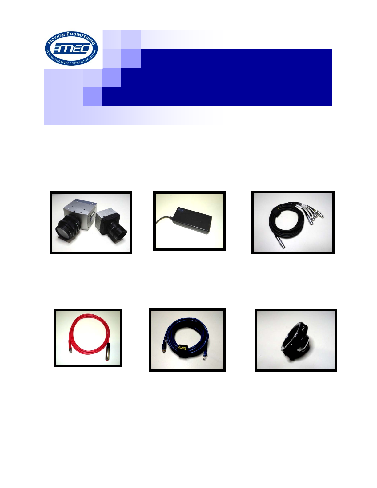
High Speed Camera System Components
Motion Engineering Company
Motion Engineering Company
Motion Engineering Company
Motion Engineering Company
Motion Engineering Company
Motion Engineering Company
Motion Engineering Company
Motion Engineering Company
Motion Engineering Company
Motion Engineering Company
Motion Engineering Company
Camera Body
AC Power
Multi-Wire Pigtail
F-C Mount Adapter
Ethernet Cable
Trigger Cable
Motion Engineering Company
Input/ Output Cable
1
17338 Westfield Park Road, Suite 4
Westfield, IN 46074
800-447-7291
Page 2
DAMAGE TO EQUIPMENT FOR IMPROPER CONNECTION BETWEEN CAMERA,
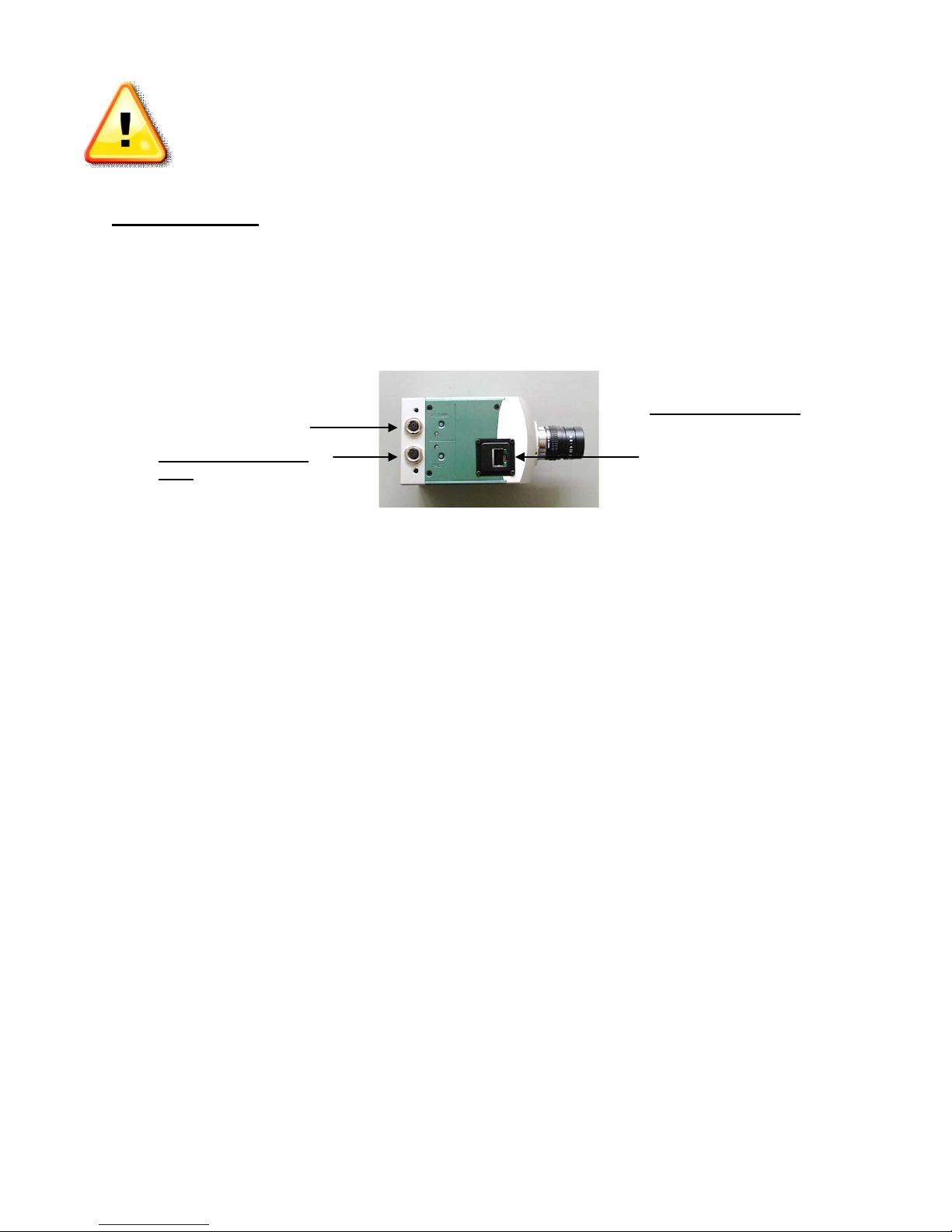
Power Supply Port
Multi-Wire Pigtail I/O
Gigabit Ethernet Port:
port on laptop
CABLES, AND COMPONENTS IS AT CUSTOMER’S RISK….See Rental Agreement
for clarification.
Instructions:
1. Connect the Power Supply to the Power Supply Port on the Camera Body.
2. Connect the Multi-Wire Pigtail I/O Cable to the Multi-Wire Pigtail I/O Port on the
Camera Body.
Port:
“Trig” for connecting I/O
cable to trigger cable
Ethernet cable goes from
camera body to Ethernet
3. Connect the Manual Trigger Cable to the “DIG4/TRIGGER” connector on the Multi
Wire Pigtail Input/ Output Cable.
4. Connect the CAT-6 Ethernet Cable between the Laptop and the back of the Camera
Body.
5. Connect the Laptop Power Supply and then turn on the Laptop.
6. At the Windows “Log On” Screen, type “pci” as the User Name, and “pci” as the
Password.
7. Once the camera is connected to the laptop, you will see an icon with a yellow triangle
with exclamation point over the network connection icon located on the bottom
right of the desktop. (Note: This may take a minute or two)
8. After camera is connected, double click on the “HiSpec Director II” software icon
located on the desktop.
2
Page 3
9. Attach the desired lens to the Camera Body. C-Mount Lenses connect directly to the
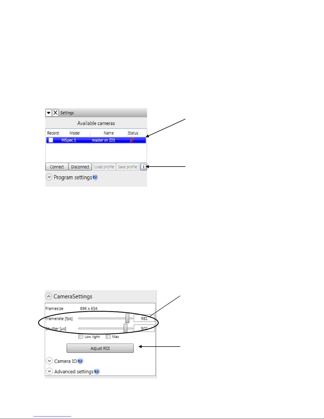
Connected camera (s) are displayed with
Adjust Frame Rate and
Adjust the Region of
Connected camera(s) are
Click the “i” icon to rename
camera(s)
camera (no need for adapter). Nikon F-Mount Lenses require the “F-C Mount Adapter”.
10. Once the software has loaded the camera Model, Name, and Status should be shown in
the upper left had side of the window, under “Available Cameras”.
displayed with their status.
Select camera(s) and press
“Connect” or Double Click
on camera(s) name to connect
camera(s) to Director II
Software
11. Select connected camera and then “Connect” or Double-Click Camera Name.
12. Select desired Frame Rate, Resolution, Shutter Speed, and Trigger Mode.
Adjusting Frame Rate & Shutter:
Shutter speed by either
using scrol l bar or clicking
on number box (right of
scroll bar) and typing in
desired value via keyboard.
Interest “ROI” by clicking
the button, then adjusting
either offsetX, offsetY
values, mo ving the red
rectangle, or the green
rectangle to desired area.
3
Page 4
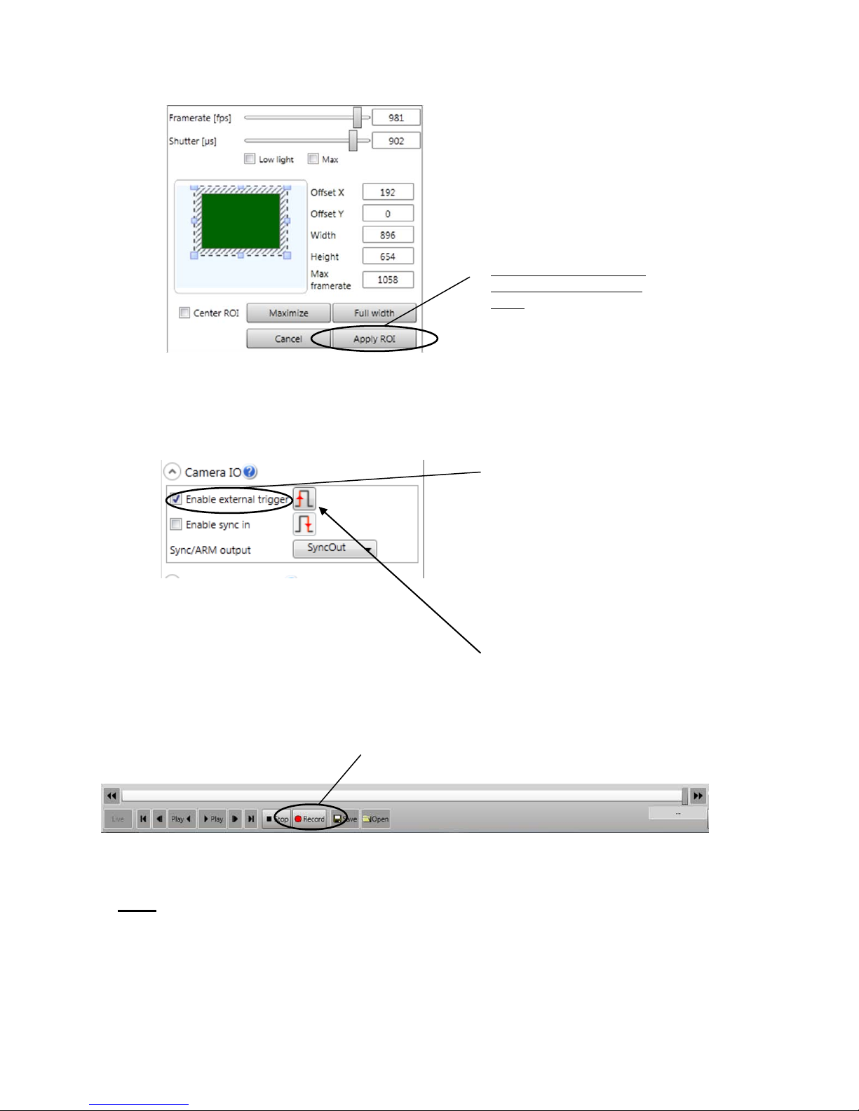
If adjusting the “ROI”,
If using an e xternal hardware
Adjusting ROI:
Adjusting Trigger:
To change from “rising” to
select the “Adjust ROI”
option from Camera
Settings and then edit within
this menu. Then adjust with
offset X/ offset Y values,
moving the red or green
rectangle to the desired area.
When you are done editing,
make sure to select “Apply
ROI”.
trigger, you MUST have
“Enable External Trigger”
checked. You may change
the “rising” or “fal l in g “ed ge
of the trigger, depending on
how you want to stop your
recording, by clicking on the
icon.
13. To make recording, select “Record” icon on bottom toolbar.
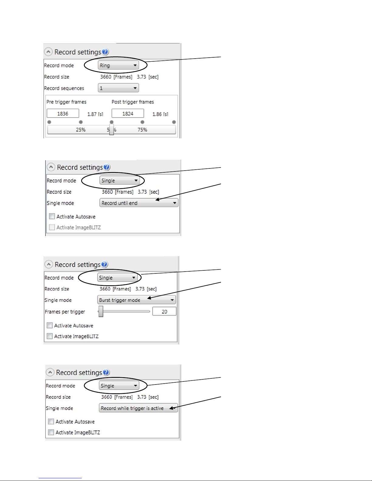
Note: There are two different Record Modes, Ring and Single. Single mode has
three different types of modes; Record until end, Burst trigger mode, and
Record while trigger is active.
“falling” click on the icon
4
Page 5
Connected camera (s) are displayed with
If in “Ring” record ing
If in “Single-Re cord until
If in “Single-B urst trigger
If in “Single-Record while
Ring Record Mode:
Single Record Mode:
Single-Record While Trigger is Active:
mode, image will be
continuously buffering (and
rewriting over itself) until
you click the t rigger button
or use F12 for software
trigger
end” mode, image will be
captured unt il the memory
buffer is full (Start)
Single-Burst Trigger Mode:
mode”, i mage will be
captured unt il the memory
buffer is full (Start)
trigger is active”, images
will be captured when
external trigger signal is
present (hardware-driven)
5
Page 6
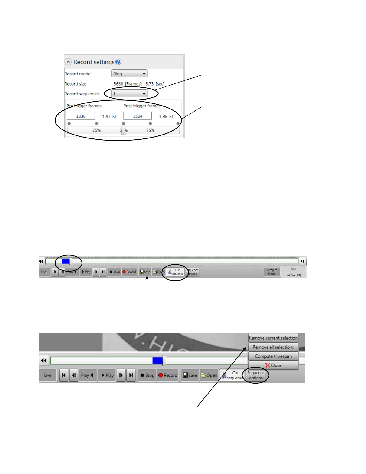
You are able to divide the memory
You are able to adjust Pre/Post
up to 16 same-sized memory ranges
Trigger frames be eithe r moving
scroll bar, or manually typing in
desired amounts in bo xes. In this
example, there will be approximately
50% of the frames captured before
and after trigger is initiated
14. Use Scroll bar to navigate to the first frame of interest within the recording. Select
“Cut Sequence”. Drag Scroll Bar through the sequence, stopping at the last frame of
interest. Select “Cut Sequence” again. The solid blue bar indicates those images will
be viewed/ saved.
15. To save image, use the “Save” icon on the toolbar to save images.
16. Once a sequence (or sequences) has been created, you can select “Sequence
Options”. To deselect the current sequences, use the “Remove Current Selection”
6
Page 7
option, or use “Remove All Selections” to deselect multiple sequences. Please note,
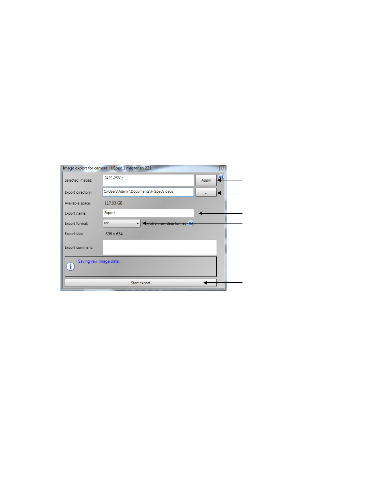
Images selected to be
Directory where
Name of file
File extension (there
choose from)
Click “Start Export” to
save
using these two options will NOT delete the actual sequence, but will just deselect them.
Use the “Compute Time span” to calculate the distance in time between sequences.
17. Select desired “Directory” and “Export Format”, and then select “Start Export” to
save images to desired directory.
saved
images will be saved
will be several to
7
 Loading...