

Page 1

6-DoF Arm Kit
Assembly Instructions
Page 2

General Warnings and Cautions
Danger (May cause serious injury or death)
• Keep water, flammables, solvents and other liquids clear from actuator.
• Never place fingers, arms, toes and other body parts near actuator during operation.
• Cut power if actuator emits strange odors or smoke.
• Keep actuator out of reach of children.
Warning (May cause injury or damage to actuator)
• Before operating, read all applicable instructions and notices found here:
http://docs.hebi.us/#quickstart-guide-x-series-actuator
• Comply with the operating temperature (-10℃ to 50℃)
• Turn off power source before connecting or disconnecting actuator power.
• Do not expose the actuator to permanent and strong magnetic fields.
• The actuator must not be exposed to dusty or wet environments.
• If actuator is under load, abruptly removing the power connection can cause permanent damage.
• Do not force screws into the bottom of the actuator.
- X5: 5mm tap depth - X8: 7mm tap depth
• Use provided hardware with accessories and hand tighten as needed.
• Do not attempt to disassemble actuator, this will void the warranty and can cause permanent damage.
For more information please visit: docs.hebi.us
X-Series 6-DoF Arm Assembly Instructions 2
Page 3
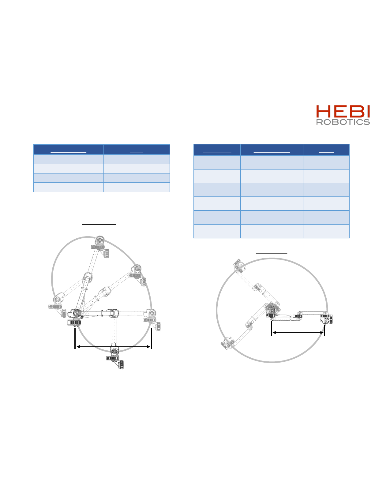
*Calculated using Default Configuration with Gas Spring.*
Using a different configuration of X-Series Actuators will
provide different payload capacities.
Technical Specifications
X-Series 6-DoF Arm Assembly Instructions 3
Specifications
Value
Weight
4 kg
Reach
650 mm
Max Continuous Payload
2.00 kg
Max Peak Payload
7.50 kg
650mm
650mm
Movement
Working Range Speed
Axis 1
– Base
[Default: X8
-9]
Continuous
(limited by wiring)
180°/s
Axis 2
– Shoulder
[Default: X8
-16]
0° to +70°
(limited by gas spring)
90°/s
Axis 3
– Elbow
[Default: X8
-9]
-155° to +155°
(avoid end effector collisions)
180°/s
Axis 4
– Wrist 1
[Default: X5
-1]
Continuous
(avoid end effector collisions)
540°/s
Axis 5
– Wrist 2
[Default: X5
-1]
Continuous
(limited by wiring)
540°/s
Axis 6
– Wrist 3
[Default: X5
-1]
Continuous
(limited by wiring)
540°/s
Side View
Top View
Page 4
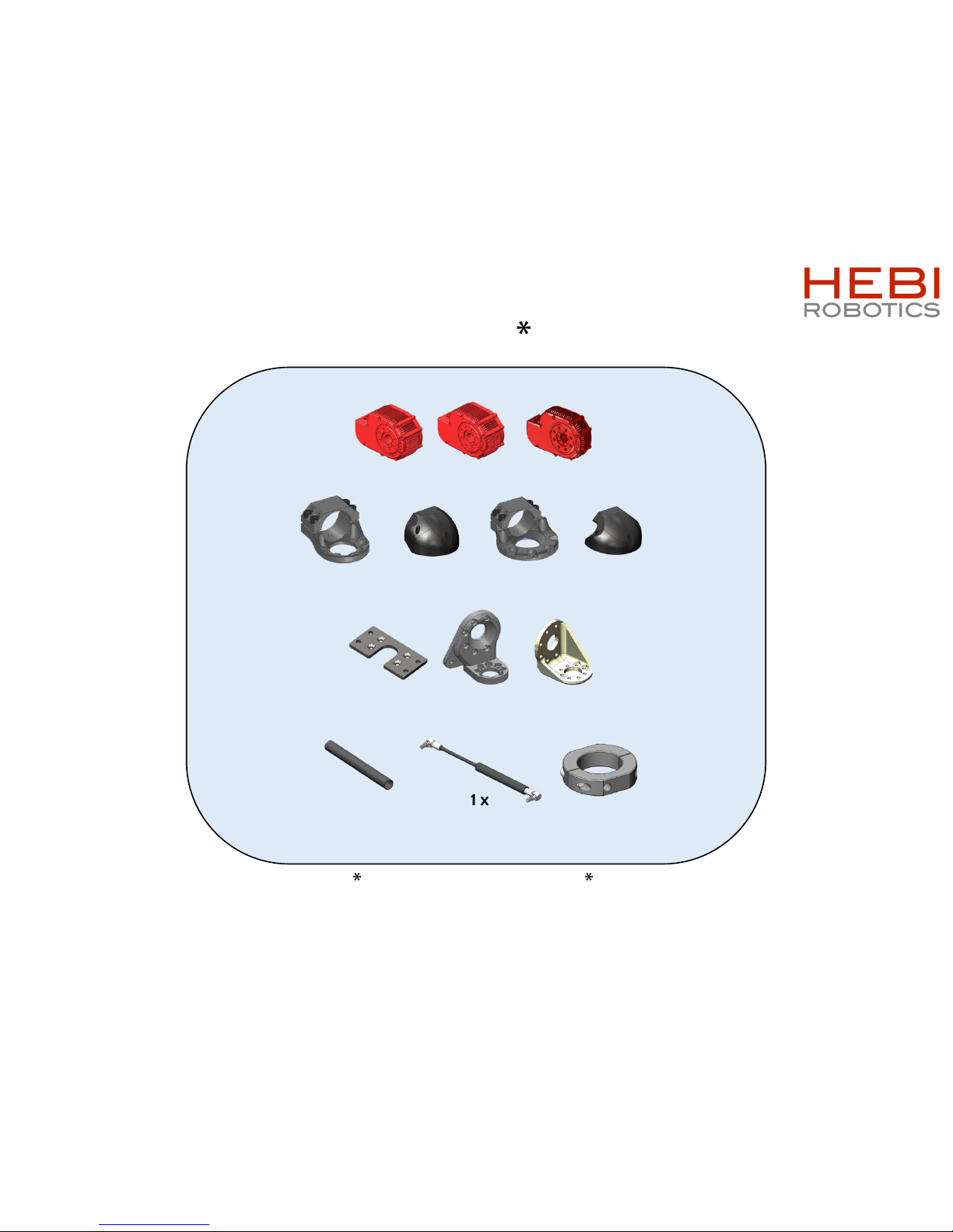
Bill of Materials - Mechanical
X-Series 6-DoF Arm Assembly Instructions 4
fasteners included, not shown
1 x
A-2040-01R
1 x
A-2043-01
2 x
A-2042-01R
2 x
A-2038-02
2 x
A-2090-01
2 x
A-2039-02
2 x
A-2091-01
2 x
PP-2200-02
[300mm]
1 x
A-2083-01
1 x
A-2088-90-30
(Gas Spring – 30lbs.)
2 x
X8-9
3 x
X5-1
Default Configuration
1 x
X8-16
Page 5
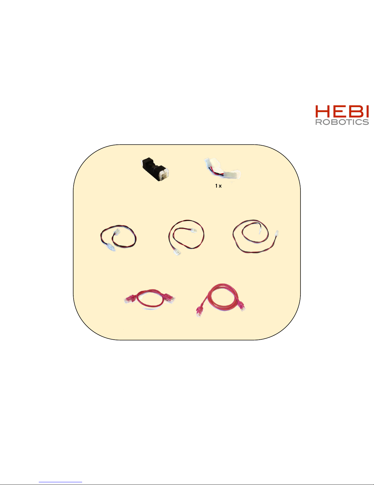
Bill of Materials - Electrical
X-Series 6-DoF Arm Assembly Instructions 5
4 x
A-2046-12
Power Cable, 12” Length
3 x
A-2046-18
Power Cable, 18” Length
2 x
A-2046-24
Power Cable, 24” Length
3 x
PP-2059-01
Ethernet Cable, 12” Length
3 x
PP-2061-01
Ethernet Cable, 36” Length
3 x
A-2128-01
Power Distribution Board
1 x
A-2048-02
Power Jumper
Page 6
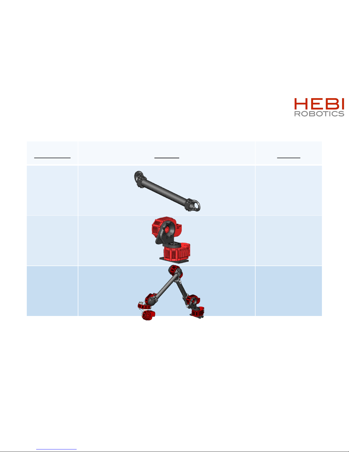
Table of Contents
Assembly Image Pages
Tubes [6]
Base [7-8]
Final [9-15]
X-Series 6-DoF Arm Assembly Instructions 6
Page 7
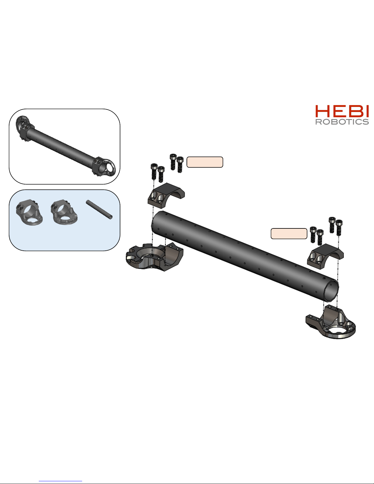
2 x
X-Series 6-DoF Arm Assembly Instructions 7
1 x
PP-2200-02
[300mm]
1 x
A-2038-02
1 x
A-2039-02
M5x16mm
M5x16mm
Page 8
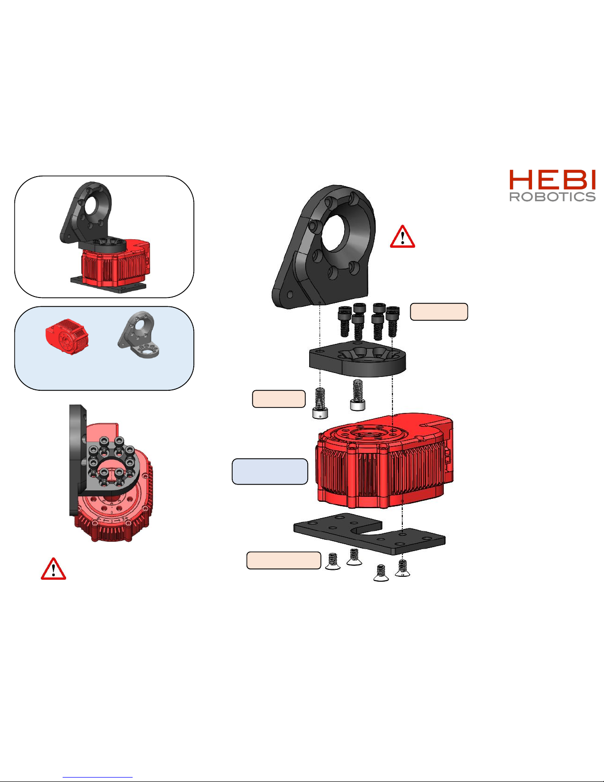
1 x
X-Series 6-DoF Arm Assembly Instructions 8
Axis 1: Base
Default X8-9
Step 1 of 2
Step 2 of 2
1 x
A-2040-01R
M6x12mm
M5x12mm
M5x10mm FHCS
1 x
X8-9
Align with actuator
output hub tick mark
(face parallel with tick mark and
mounting hole pointed on same side)
Flat face towards outside
Page 9
X-Series 6-DoF Arm Assembly Instructions 9
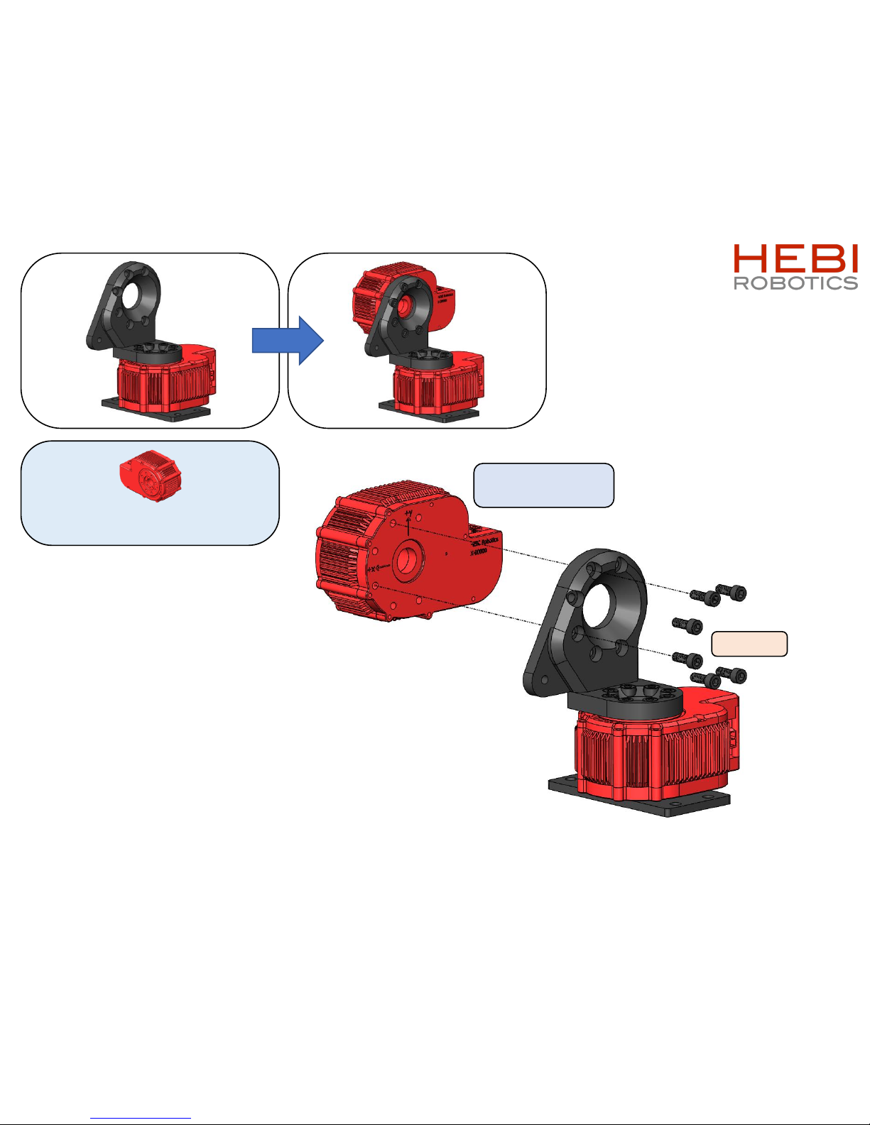
Axis 2: Shoulder
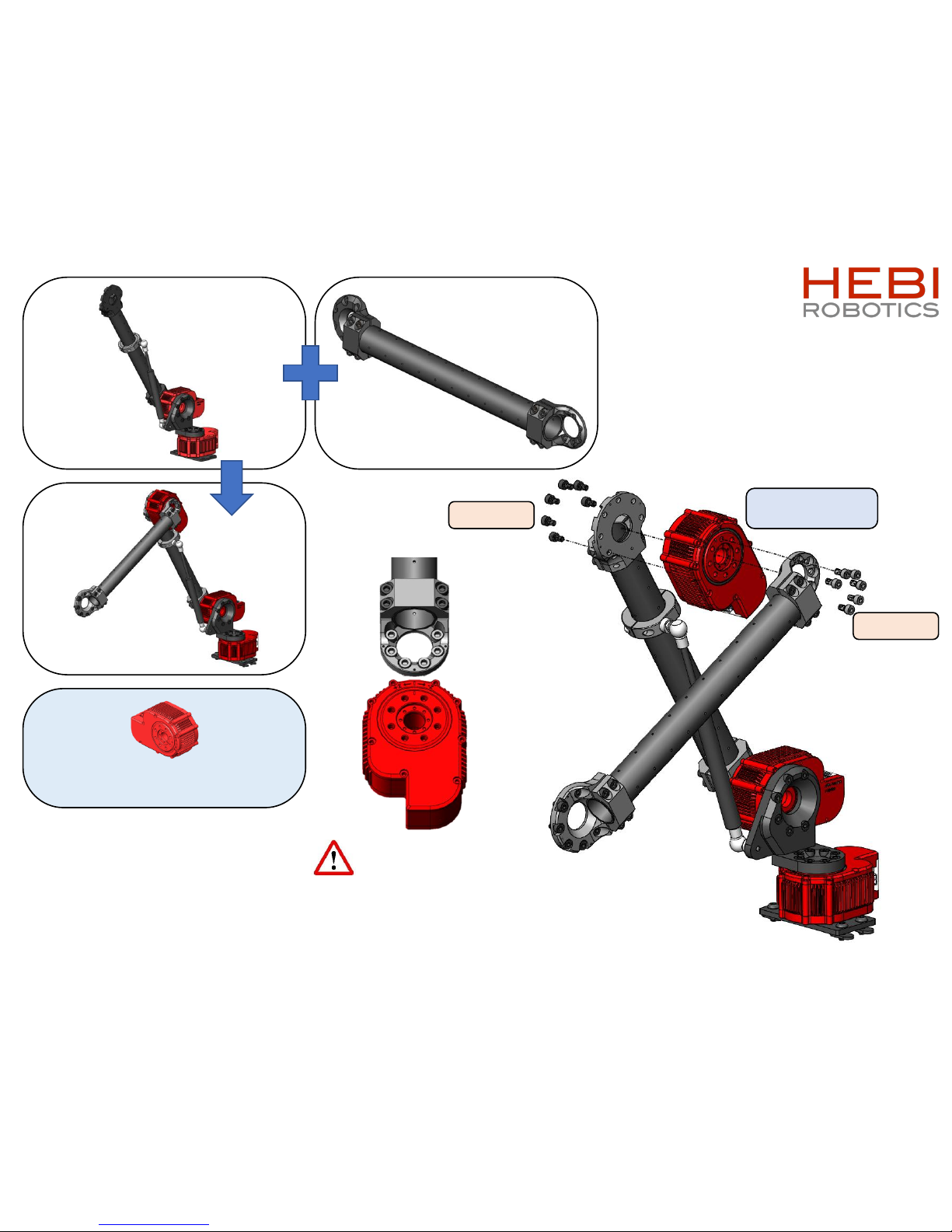
Default X8-16
1 x1 x
M5x14mm
1 x
X8-16
Page 10
X-Series 6-DoF Arm Assembly Instructions 10
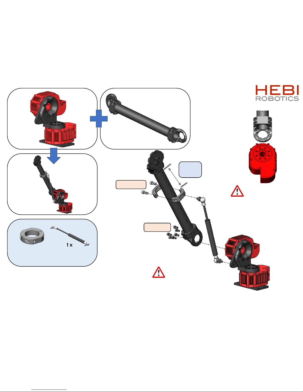
1 x1 x
1 x
¼-28 x 5/8”
63.5mm
[2.5in]
1 x
A-2088-90-30
(Gas Spring – 30lbs.)
M5x10mm
1 x
A-2083-01
Align with actuator
output hub tick mark
(Tube aligns with tick mark)
Gas springs require
washer for flush mounting
(included in A-2088-90-30)
Page 11
X-Series 6-DoF Arm Assembly Instructions 11
1 x1 x
1 x
M5x10mm
M5x8mm
Axis 3: Elbow
Default X8-9
Align with actuator
output hub tick mark
(Tube aligns with tick mark)
1 x
X8-9
Page 12

X-Series 6-DoF Arm Assembly Instructions 12
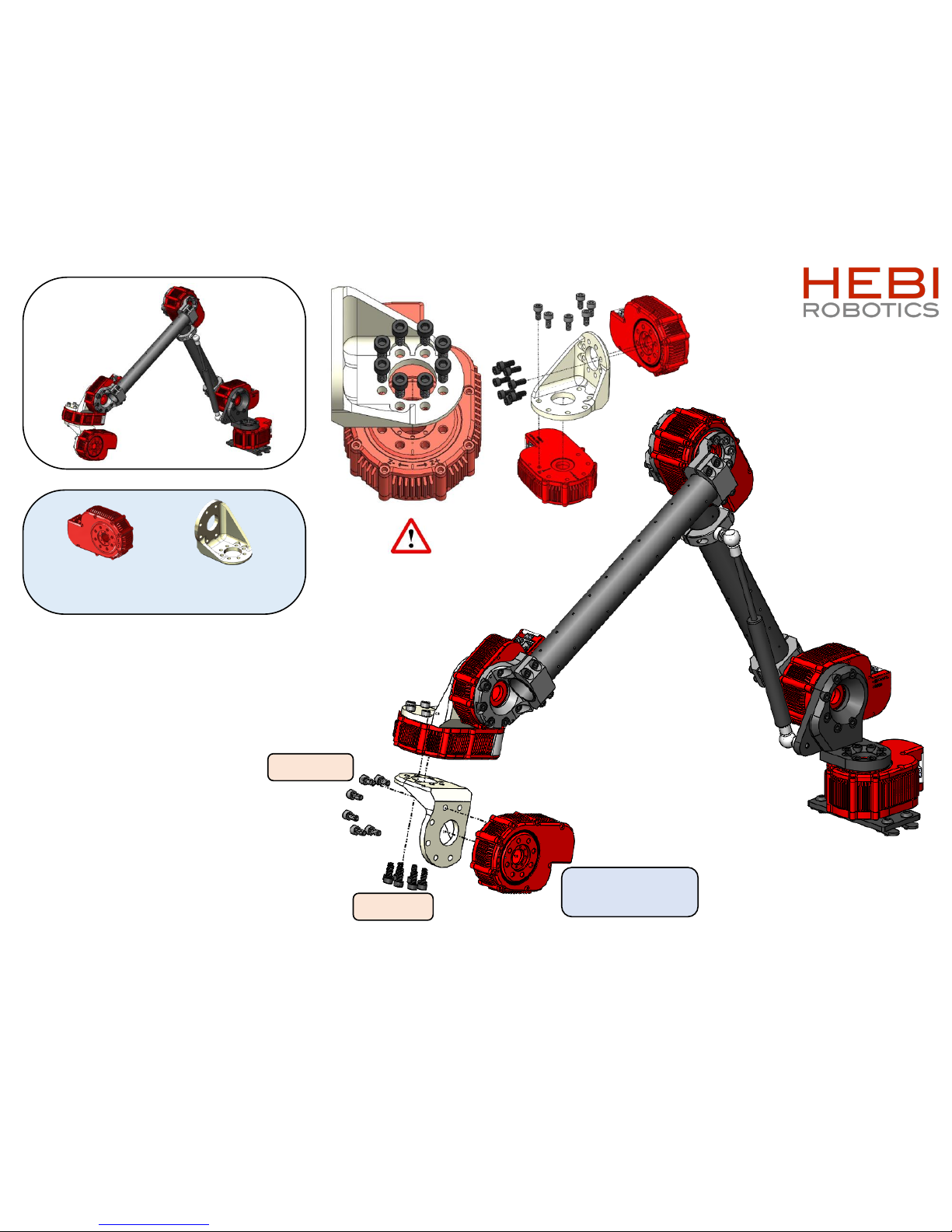
1 x
2 x
X5-1
1 x
A-2042-01R
M5x12mm
M5x10mm
Axis 4: Wrist 1
Default X5-1
M5x8mm
Axis 5: Wrist 2
Default X5-1
Align with actuator
output hub tick mark
Page 13
X-Series 6-DoF Arm Assembly Instructions 13
1 x
1 x
X5-1
1 x
A-2042-01R
M5x12mm
M5x10mm
Axis 6: Wrist 3
Default X5-1
Align with actuator
output hub tick mark
Page 14
Wiring Notes
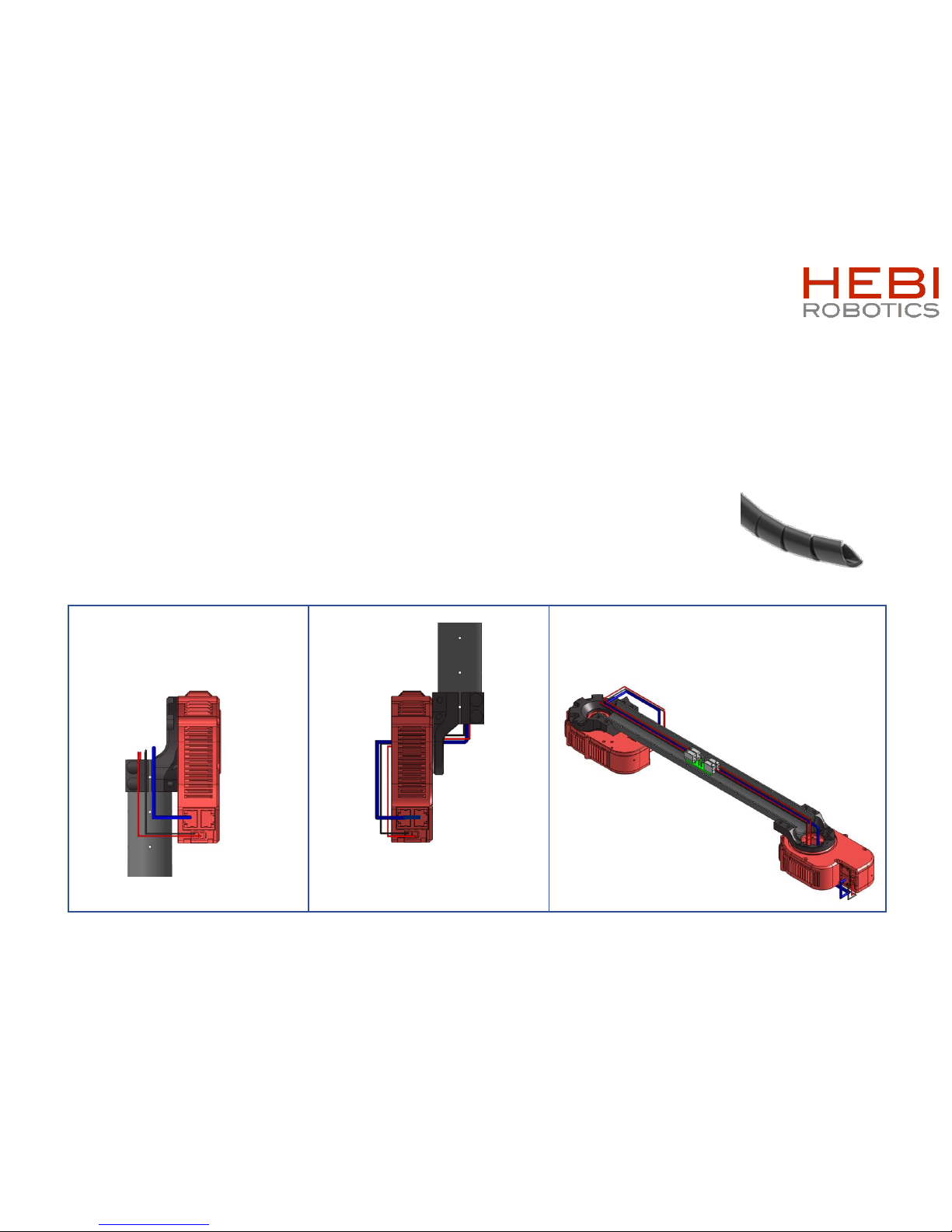
• Keeping wires organized will help prevent tangling and add a nice aesthetic.
• Spiral sleeving is a good accessory for organizing loose wires
• HEBI X-Series actuators have a thru bore specifically designed to fit ethernet and power connectors.
• Please pass connectors thru bore hole 1 at a time.
For more information visit: docs.hebi.us
X-Series 6-DoF Arm Assembly Instructions 14
[Spiral sleeving]
Wires that come from the
previous joint should be inserted
directly to actuator ports.
Wires that connect to the next
joint should be threaded through
the actuator’s bore hole.
Power distribution boards are included to help
daisy-chain power connections.
These fit well within the tubes between actuators.
Page 15
X-Series 6-DoF Arm Assembly Instructions 15
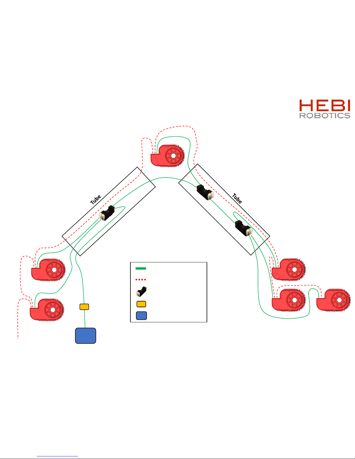
Wiring Diagram
24”
18”
12”
12”
18”
18”
network
24”
12”
36”
36”
12”
36”
12”
12”
12”
Base
Shoulder
Elbow
Wrist 1
Wrist 2
Wrist 3
Power Cable
Ethernet Cable
Power Distribution
Power Supply
Power Jumper
Page 16
X-Series 6-DoF Arm Assembly Instructions 16
1 x
2 x
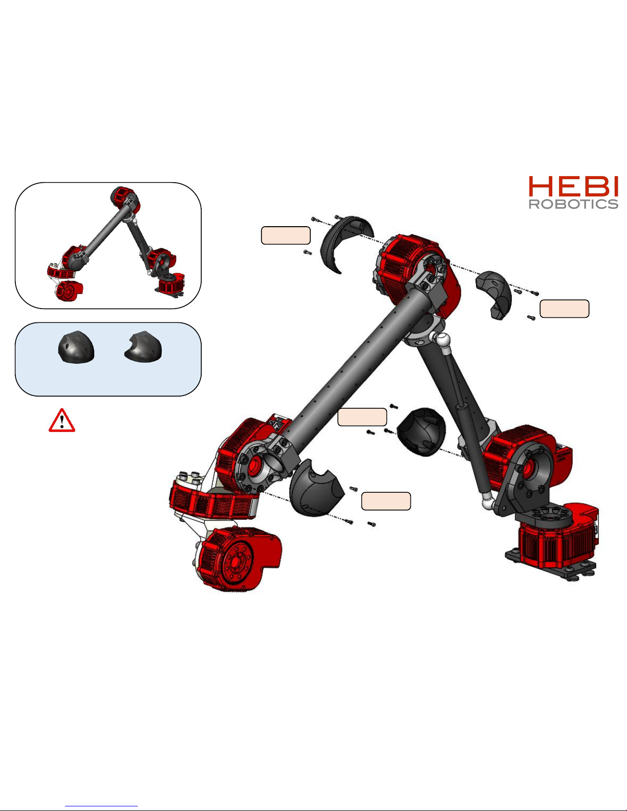
A-2090-01
2 x
A-2091-01
Install cables before
adding caps
M2x8mm
M2x8mm
M2x8mm
M2x8mm
Page 17
X-Series 6-DoF Arm Assembly Instructions 17
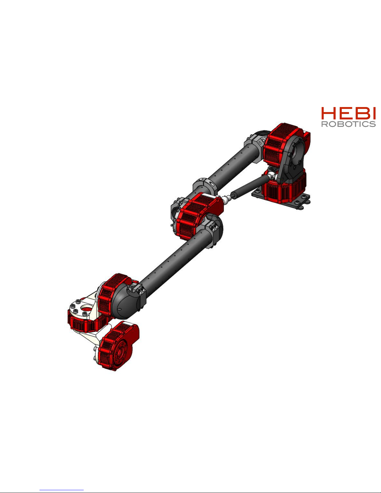
All axes at zero degrees
Page 18
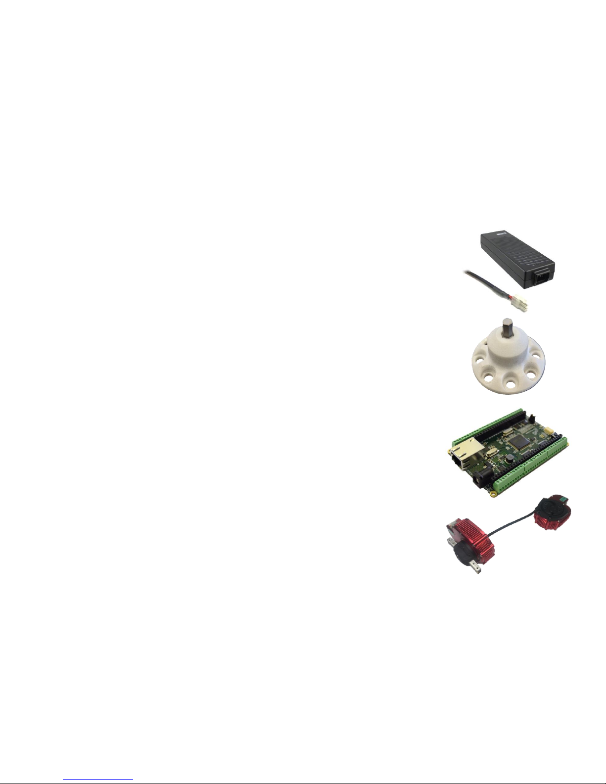
• Power Supply, 24V 220W (A-2098-24)
• Comes with correct Molex Minifit Jr 2 connector
• Magnet embedded end effector (A-2081-01)
• Interfaces with hex shaft driver bits for screwing/bolting tasks
• Screwdriver bits not included
• HEBI I/O Board (A-2116-01)
• Integrate with 3rdparty end effectors or tools using HEBI APIs
• HEBI Gripper
• Cable driven gripper keeps weight away from end of arm
• *Modules sold separately*
X-Series 6-DoF Arm Assembly Instructions 18
Additional Accessories
Page 19

X-Series 6-DoF Arm Assembly Instructions 19
© HEBI Robotics 2018
 Loading...