

Page 1
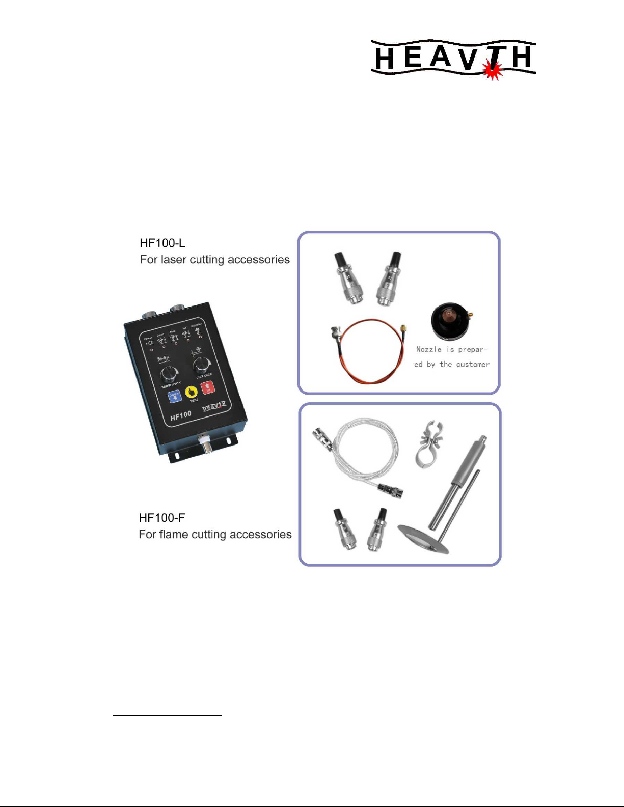
HF100
Capecitance Height Controler
TECHNICAL MANUAL
VISION:1302
CHANGZHOU HEAVTH SCIENCE&TECHNOLOGY CO.,LTD.
136# HUBIN ROAD NIUTANG TOWN CHANGZHOU CITY JIANGSU IN CHINA
TEL:86-0519-89182619
FOX:86-0519-89183619
Http://www.heavth.com
Page 2

HF100 CapecitanceHeightControler
http://www.heavth.com
第 - 2 - 页 共 14 页
TABLE OF CONTENTS
1 IMPORTANT INFORMATION ................................ 5
1.1 SERVICE ASSISTANCE AND CONTACT INFORMATION............................... 5
1.2 RECEIVING AND UNPACKING ................................................................. 5
1.3 SAFETY CONSIDERATIONS .................................................................... 5
1.4 PRE-INSTALLATION CONSIDERATIONS ................................................. 5
1.5 REPLACEMENT PARTS ........................................................................ 6
Part Names ................................................................................ 6
1.6 CONFIGURING THE LIFTER MECHANICS ................................................. 6
Motor............................................................................................ 6
2 GENERAL DESCRIPTION .................................. 7
2.1 GENERAL DESCRIPTION .................................................................. 7
2.1.1 Front Panel Components .............................................................. 9
2.1.2 Modes........................................................................................... 10
2.1.2.1Auto mode ...................................................................................... 10
2.1.2.2Manual mode ................................................................................ 10
Auto and Manual Mode Specifications .................................... 10
2.1.3 Limit Switches ............................................................................. 10
Limit Switches Specifications ......................................................... 10
3 INSTALLATION......................................... 11
3.1 DEFAULT SETTINGS AND DIP SWITCH............................................. 12
3.1.1 Position Signal and Remote Operator Control Settings ............ 12
3.1.2 Clock Frequency and Maximum Motor Current........................ 14
4 START-UP CHECKS..................................... 15
Directions for P16 Pin
Manual/Auto and Up/Down switches......................................... 15
4.1 ADJUSTING THE MEASURING SYSTEM................................................... 16
4.2 CLEARANCE AND SENSITIVITY TUNING.................................................. 17
5 DRAWINGS AND DIAGRAMS............................... 18
Page 3

HF100 CapecitanceHeightControler
http://www.heavth.com
第 - 3 - 页 共 14 页
1 IMPORTANT INFORMATION
1.1 SERVICE ASSISTANCE AND CONTACT INFORMATION
For service assistance, have the following information available:
• HF100 model, part and serial number located on a label
• Type of cutting application you are using
You can contact our at:
TEL: 086-0519-89182619
FOX: 086-0519-89183619
1.2 RECEIVING AND UNPACKING
After receiving the HF100 you should:
• Carefully, unpack and inspect the equipment.
• Compare the received shipment with the packing list.
• Report any damage to the carrier and your representative.
• Store equipment that will not be used in a clean, dry location.
• Take appropriate precautions to prevent moisture, dust and dirt
from accumulating in storage and installation areas.
1.3 SAFETY CONSIDERATIONS
Safety practices should not be an after thought. Before installing or
servicing the controller,
review and follow applicable policies and procedures to ensure
worker safety. Machinery must be in a safe state and you must be
aware of any additional hazards that can arise.
1.4 PRE-INSTALLATION CONSIDERATIONS
Before installing the HF100:
• Check to be sure that you have all of the required parts. Refer to
P6 of this manual.
• Familiarize yourself with the parts of the HF100 by reviewing P4
in this manual.
• Check to be sure that the torch lifter motors you are using with the
HF100 are within the acceptable range.
• Review the instructions for Configuring the Lifter Mechanics in
section 1.6 of this manual.
1.5 CONFIGURING THE LIFTER MECHANICS
Proper configuration of the torch lifter mechanism is an important
factor for establishing the accuracy of your cutting system. Be sure
that:
• Gear reduction is selected on the torch lifter so that the maximum
suspension speed does not exceed 3000 mm/min (120 IPM). If
higher accuracy is required, maximum suspension speed should
be set to 1500 mm/min (60 IPM).
• Gears, racks and spindles have minimal backlash.
• Oversizing is avoided. The mass of moving parts, including
armature inertia must be as small as possible. Motors with low
nominal RPM are preferred.
• Only DC motors with the following ratings are used:
MOTOR RATINGS: DC MOTOR
MOTOR VOLTAGE: DC24V
MAX CURRENT: 6A
Page 4
HF100 CapecitanceHeightControler
http://www.heavth.com
第 - 4 - 页 共 14 页
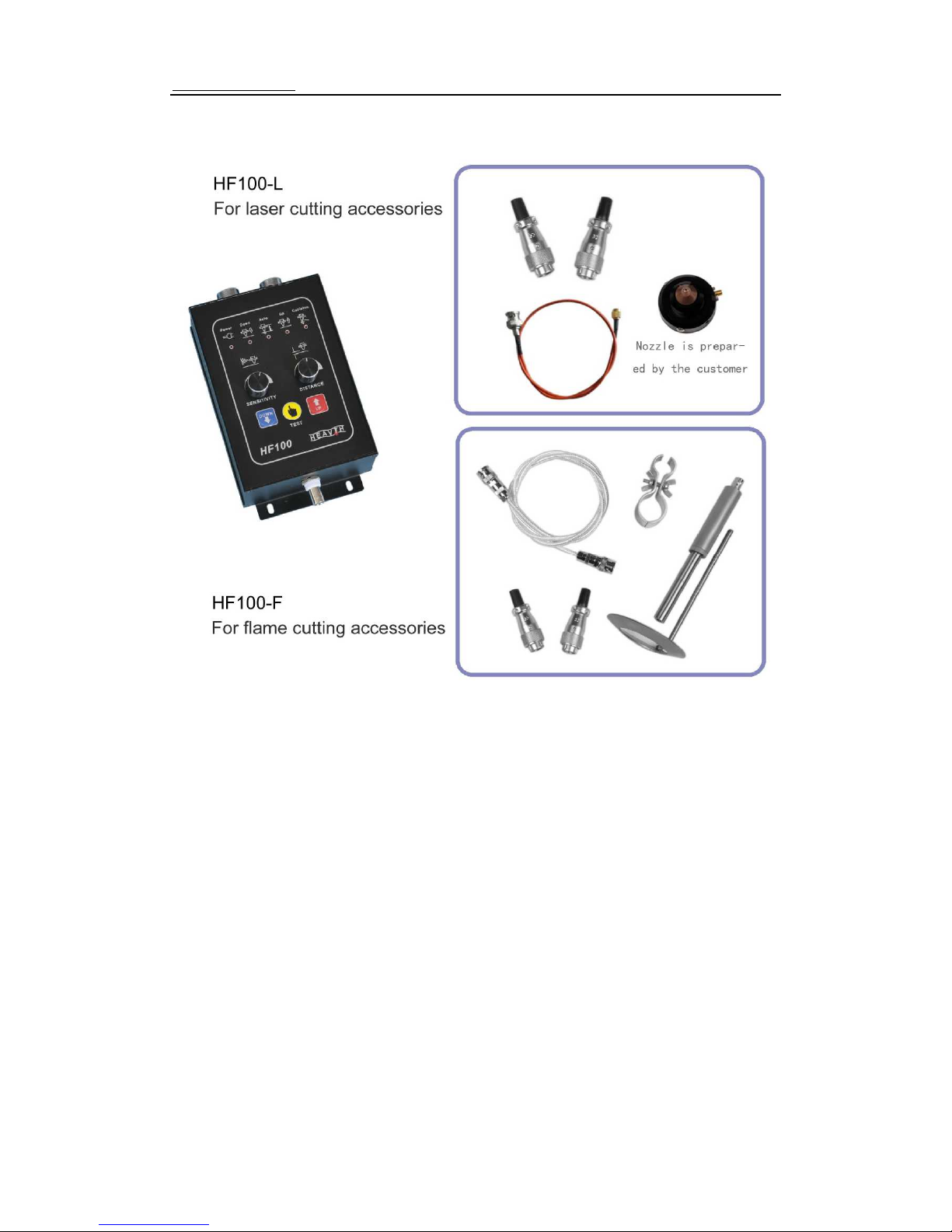
1.6 PARTS
HF100 Part Names:
HF100-L include: connector,high-frequency cable
HF100-L include: connector,high-frequency cable,flexible coupling,
torch clamp,ring sensor。
Page 5

HF100 CapecitanceHeightControler
http://www.heavth.com
第 - 5 - 页 共 14 页
2 GENERAL DESCRIPTION AND SPECIFICATIONS
2.1 GENERAL DESCRIPTION
The cut quality for thermal cutting processes is affected by the
amount of clearance between the torch tip and cutting material.
Automatic control of the clearance span lets you make a smooth,
quality cut at higher speeds with the least amount of dross.
HF100 lets you achieve and maintain the optimum amount of cut
clearance and can provide the following economical advantages:
• Less preparation time because the HF100 controller quickly
establishes the correct amount of clearance.
• Increased productivity as a result of higher cutting speeds.
• Optimum cut quality, reducing or eliminating the need for
secondary processing.
• Identical cut quality on all machines.
• Fully automatic CNC machines.
The HF100 controller also provides the following advantages:
• Clearance is measured using a capacitive system allowing
reproducible setting and maintenance of the once adjusted
clearance.
• The lifter motor is controlled by a transistorized H-bridge Pulse
Width Modulated (PWM) amplifier using armature voltage feedback
and adjustable current limitation.
• For automation purposes, the integrated control logic offers an
In-position signal that can also be used to detect cut-outs or collision
with tip-ups.
• Automatic retract of the torch if the high-frequency cable is broken
or damaged. You can override this feature when in Manual mode and
continue cutting until the problem can be corrected.
• Automatic retract in Manual mode if a collision occurs with work
piece or tip-up. The retract action stops when collision is cleared.
• Visual fault codes to aid in quick troubleshooting.
• The functions are implemented in a single control box that also
contains the adjustment knobs for clearance and sensitivity.
• Upgrade compatible to HFA2 controller
HF100TECHNICAL DATA
Mains Supply: AC24V±10%,50/60 Hz, 150 W
Lifter Motor: 24 VDC MOTOR
ENV. Temperature:
Control Box: -10℃∽60℃
HF Cable: -55℃∽200℃
Senser Distance: 5mm-20mm,adjustable。
Accuracy: ±0.2mm
Length of HF Cable: 1000mm
Sensor Type: Ring
Sensor Dimensions: Outer diameter80 mm,
Inner diameter40 mm
Housing dimensions:180 mm x 100 mm x 65 mm(L×W×D)
Weight: control box 0.9 kg
control box with sensor components1.3 kg
Page 6
HF100 CapecitanceHeightControler
http://www.heavth.com
第 - 6 - 页 共 14 页
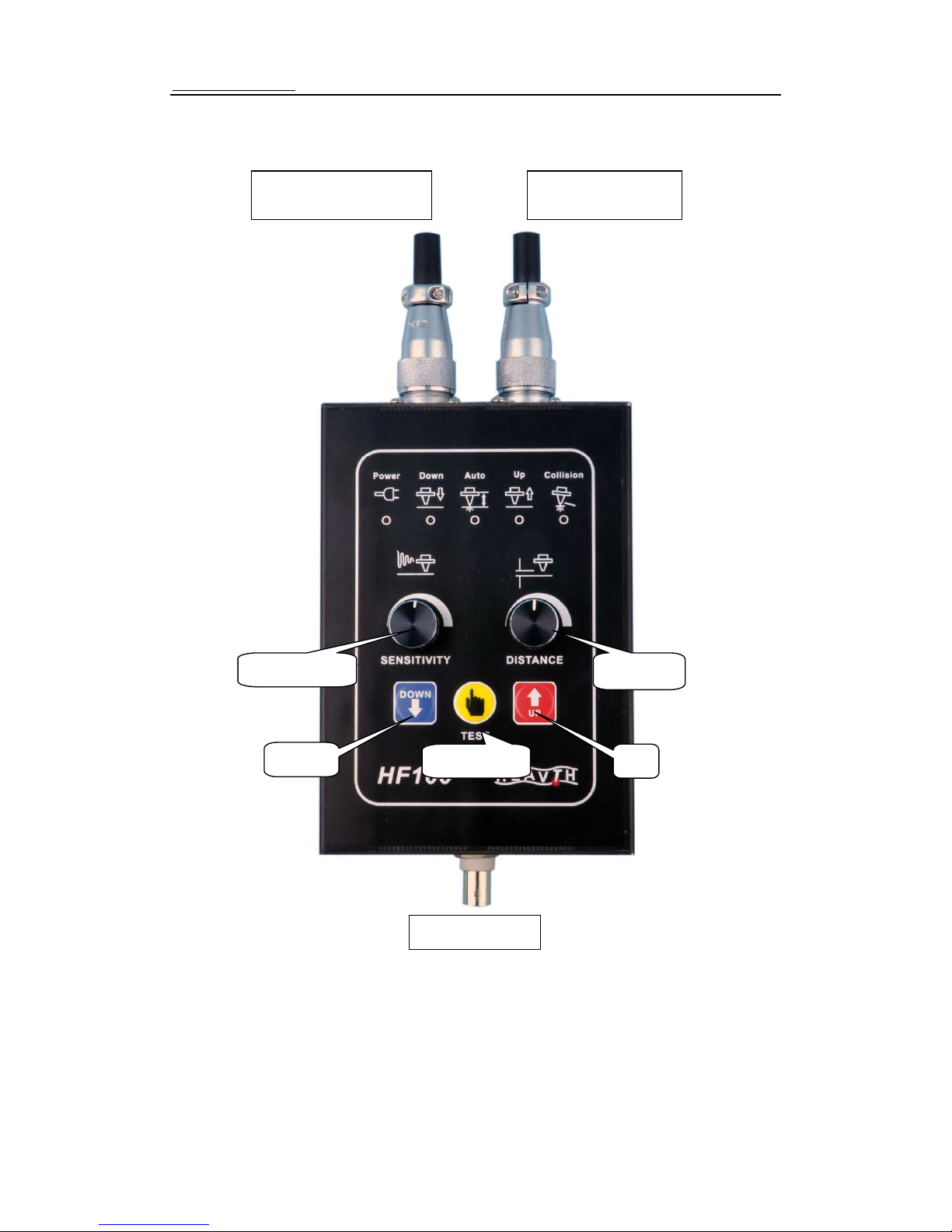
2.1.1 FRONT PANEL COMPONENTS
C
onnector X2
TO LIFTER
C
onnector X1
TO CNC
HF C
onnector
DISTANCE
AUTO TEST
SENSITIVITY
DOWN
UP
Page 7

HF100 CapecitanceHeightControler
http://www.heavth.com
第 - 7 - 页 共 14 页
2.1.2 MODES
2.1.2.1 AUTO MODE
When the contacts of the Automatic/Manual switch are closed, the
HF100 is in Automatic mode. The torch moves to the configured
clearance from the workpiece and maintains that location even when the
position of the workpiece changes.
Using the Up/Down switch manually, and while in Automatic mode,
overrides the automatic height adjustment configuration. When the
Up/Down switch is released, the torch moves back to the clearance
setting configured in the automatic height adjustment.
2.1.2.2 MANUAL MODE
When the contacts of the Automatic/Manual switch are open, the
HF100 is in Manual mode. The position of the torch is controlled using the
Up/Down switches and the lifter moves at the maximum speed. When the
Up/Down switch is released, the action of the lifter is stopped using
dynamic braking to allow for exact manual positioning. If both the
Up/Down inputs are operated at the same time, the torch moves upward.
Automatic and Manual Mode Specifications
voltage range: 0 TO 5 VDC
greater than 4 volts automatic
less than 2 volts manual
maximum input current: 10 mA
2.1.3 LIMIT SWITCHES
Limit switches impede the movement of the torch lifter when they are
triggered. The HF100 supports only normally
closed limit switches so that malfunctioning limit switches can be
recognized by the control.
Limit Switch Specification Information
voltage range: 0 TO 5 VDC
greater than 4 volts the torch lifter is disabled
less than 2 volts the torch lifter is enabled
maximum input current: 10 mA
3 INSTALLATION
The following section provides you with the procedure to follow when
installing the HF100. Some of the steps direct you to other sections in this
manual that provide you with more detailed instruction.
1. Attach the flexible coupling to the coaxial tube using the M10 thread.
Tighten the locking nut using an 11/16 inch (17mm) wrench. The flexible
coupling located between the coaxial tube and ring sensor lets the sensor ring
deflect in case of a collision.
2. Attach the ring sensor to the flexible coupling and tighten the attachment
screw using a Phillips-head screwdriver. Position the sensor so that the torch
is aligned in the center of the ring to ensure proper operation. Align the tip of
the torch and the lower edge of the ring sensor to achieve high resolution and
avoid collisions between the sensor ring and torch tip. The sensor ring can be
installed as high as 1/8 of an inch (3 mm) above the torch tip.
3. Determine a mounting location for the HF100. Keep the following points in
mind:
To avoid overheating and potential damage to the control box from cutting
Page 8

HF100 CapecitanceHeightControler
http://www.heavth.com
第 - 8 - 页 共 14 页
process fumes, Do not choose a mounting location directly above the torch.
Find a mounting location towards the side or back of the torch lifter unit.
Choose a location for the HF100 that lets you access all four (4) of the screws
that fasten the front cover control box to the back plate and completely remove
the control box from the back panel.
4. Mount the HF100 using two M4 screws (not included) with a maximum
length of 3/10” (8 mm).
5. Completely remove the four (4) screws, two on each side of the HF100,
and then remove the control box from the back plate. Save the screws for later
use.
6. Re-attach the control box to the back plate but do not secure using the
screws.
7. Attach one end of a high-frequency cable to the top of the coaxial tube
using the Bayonet Neill Concelman (BNC) connector. When determining the
length of HF cable to use, be sure to choose a length that accommodates for
the full lowering of the torch.
8. Attach the free end of the HF cable to the control box using the BNC
connector.
9. Attach the wires from the lifter motor and lifter limit switches to a
connector and then to the control box at the X2 receptacle. Be sure to install
the key plug into the connector to prevent crossing the X1 and X2 connections.
To reduce noise emission, 20 AWG (0.5 mm2) shielded cable is recommended.
Filters consisting of a resistor and capacitor can be connected only directly to
the motor. Refer to Figure 7 for wiring connections.
10. Connect a 12 AWG (2.5 mm2) ground wire to the ground screw located
on the control box and then, to the machine ground rail of your cutting system.
Page 9
HF100 CapecitanceHeightControler
http://www.heavth.com
第 - 9 - 页 共 14 页
3.1 Set controller
3.1.1 Collision output to CNC
HF100 has Anti-collision function,it is effective on both manual/auto mode.
When steel or other conductive item touches sensor ring, torch lift up, and the
collision signal is sent out from the Pin3 of 7-pin socket(OC door), when CNC
receives this signal, machine pauses and waits for treatment of collision. When
collision happens, the LED indicator(collision) on operation panel turns on.
Normally human’s hand touches sensor ring, indicator would turn on and
send out collision signal. If user changes HF cable, or HF cable spec changes,
indicator might turn on, like follow situation, HF cable short-circuit, once it
happens, indicator turns on, torch lift up. It could be confirmed by checking the
HF cable shield net and Signal connect or not. HF cable gets longer, it needs
to adjust to find the Balance point, then THC can work right on Auto mode, and
indicator will turn off.
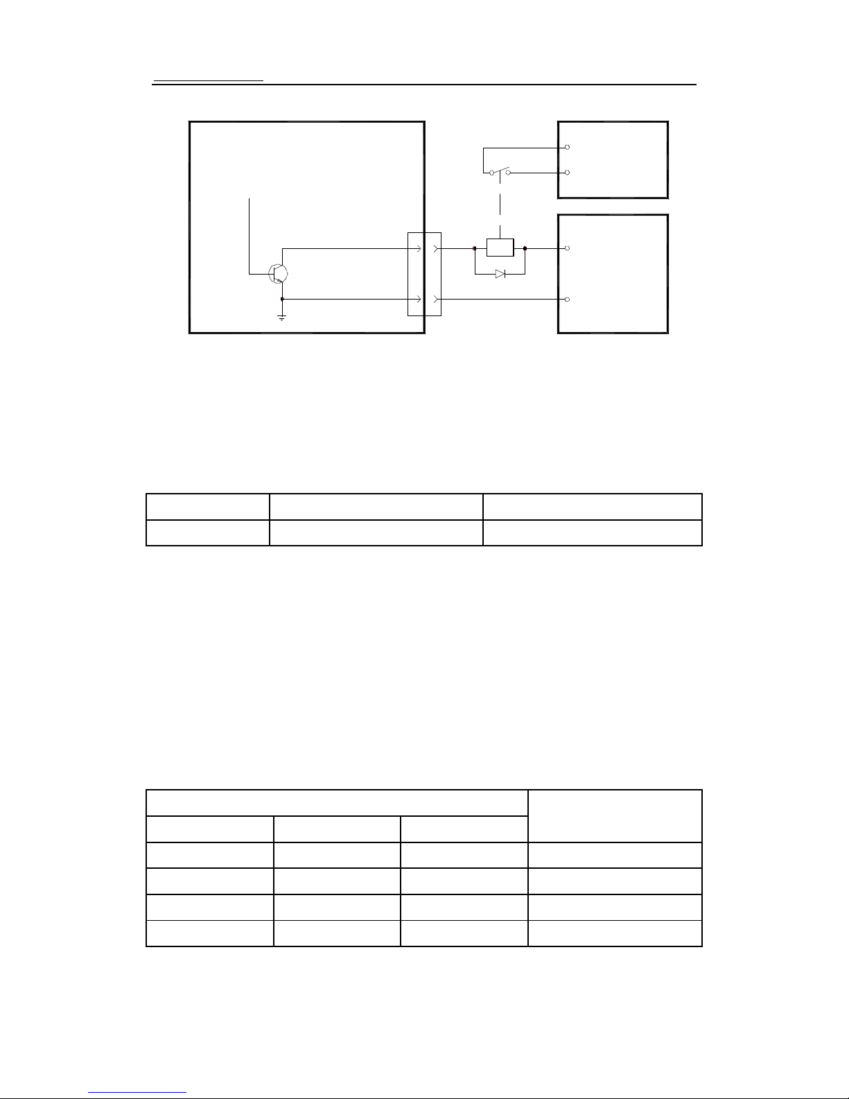
Collision Signal Details:
type:open-collector signal that can operate an external relay
connection: X1PIN 7、PIN 3
input voltage: 50 VDC maximum
input current: 0.15 Amp maximum (<1 mA of leakage)
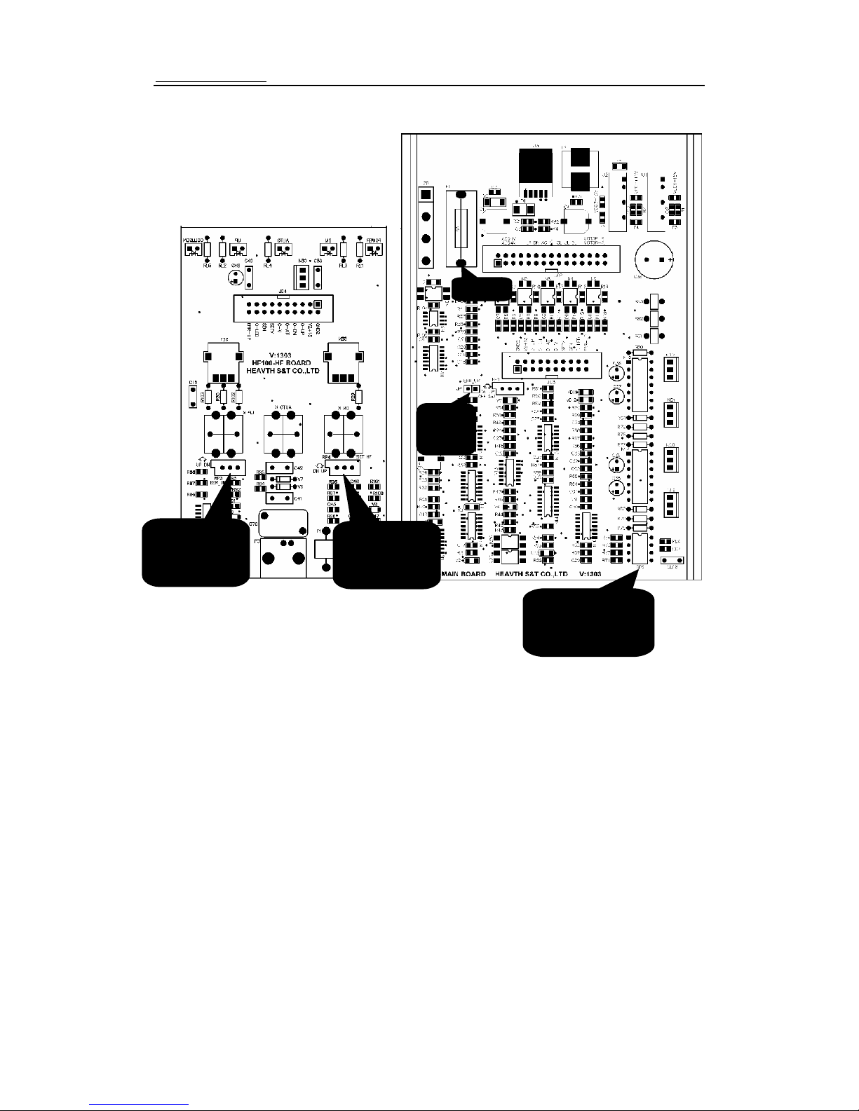
RP4
Balance
point
adjustor
RP3
Disconnection
adjustor
D
iscon
Jumper
Fuse
SP2
Frequency/current
Set
Page 10
HF100 CapecitanceHeightControler
http://www.heavth.com
第 - 10 - 页 共 14 页
Collision Signal Connection
3.1.2 SPEED CONTROLLER CLOCK FREQUENCY AND MAXIMUM MOTOR CURRENT
Use the toggle switches on DIP switch SP2 to configure the speed
controller clock frequency and maximum lifter motor current value.
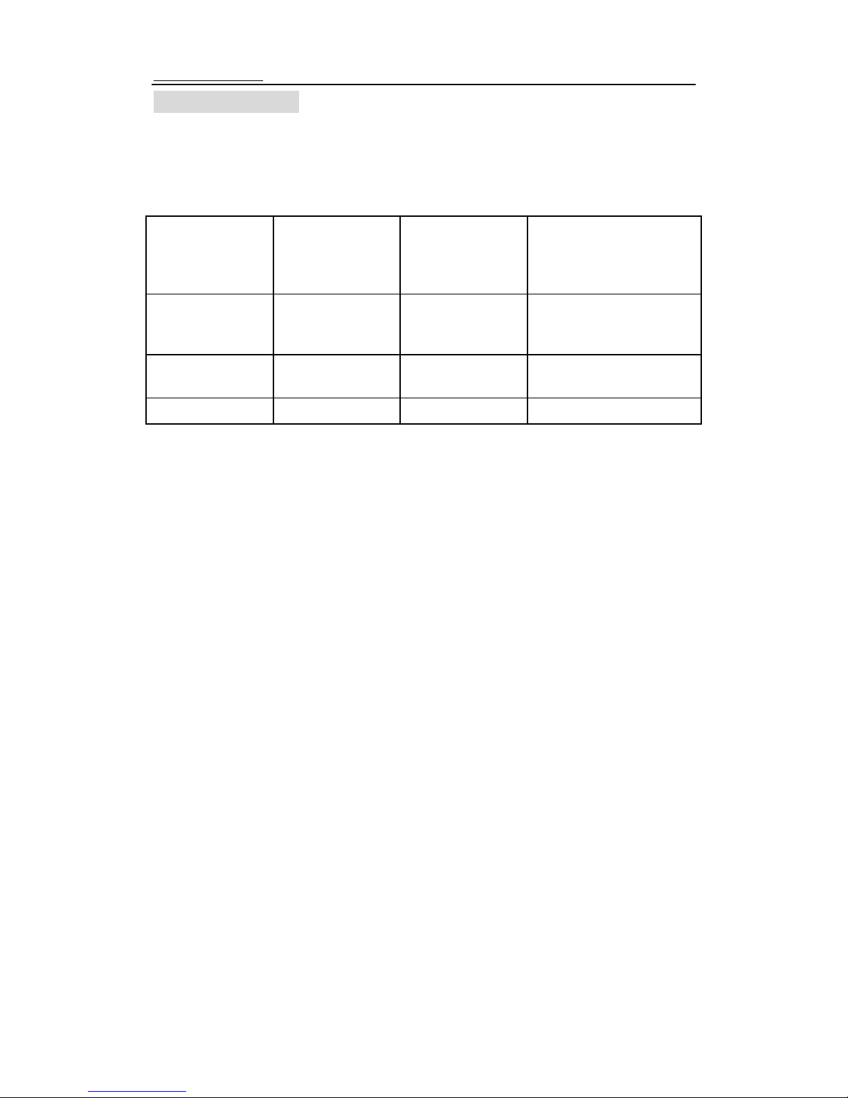
Setting Toggle Switch 1 of DIP Switch SP2:
Switch: To the ON position To the OFF position
1 18KHz 9KHz
Setting the controller clock frequency to 18 kHz requires that you take the
proper shielding and grounding precautions when running the lines to the lifter
motor. Following the proper wiring precautions ensures that the permissible
noise field intensity is not exceeded.
Using a controller clock frequency of 9 kHz meets the 10 kHz interference
suppression restrictions;however a whistling noise may be heard.
The position of toggle switches 2, 3 and 4 on DIP switch SP2 determine the
maximum current for the lifter motor.
To determine the correct amperage maximum value for the lifter motor,
refer to the lifter motor rating plate or the instruction manual that accompanied
the motor. Then, refer to Table I to set the toggle switches for DIP
Setting Toggle Switches 2, 3 and 4 of DIP Switch SP2
Set the toggle switches to this position:
Switch 2 Switch 3 Switch 4
maximum
current:
OFF OFF OFF 4A
OFF OFF ON 3A
OFF ON ON 2A
ON ON ON 1A
HF100
Collision
Signal
COM
DC
POWER
CNC
X1
7
3
RELAY
24V +24V
0V
Page 11
HF100 CapecitanceHeightControler
http://www.heavth.com
第 - 11 - 页 共 14 页
4 START-UP CHECKS
Before performing the start-up checks, be sure that you have successfully
completed the installation steps outlined in section 3 of this manual.
1. Disconnect the Connector from the X1 receptacle.
2. Check the resistance between the Automatic/Manual and Up/Down switches
using an ohmmeter.
Place one of the
leads of the
ohmmeter in pin
number:
Place the other
lead of the
ohmmeter in pin
number:
Then, The ohmmeter display
should show:
6 3 push the torch
UP
switch
<10 Ohms
5 3 push the torch
DOWN switch
<10 Ohms
4 3 AUTO MODE <10 Ohms
3. Reconnect the Connector to X1 and set the lifter to Manual mode.
4. Apply the main power supply to the controller. The lifter must not move.
5. Verify the LED located on the front panel of the Controller.
6. Briefly push the Up/Down switch to the DOWN position. The torch lifter must
travel downwards for as long as the switch is pressed. Briefly push the Up/Down
switch to the UP position. The torch lifter must travel upwards for as long as the switch
is pressed. If the lifter direction of travel does not correspond to the Up/Down switch
positions, the field or armature connections of the lifter motor must be changed. Refer
to section 6 in this document for trouble shooting information.
7. Verify that the lifter travel limit switch assignments correspond with torch lifter
direction of movement by performing the following checks:
Move the Up/Down switch to the DOWN position and then trigger the
corresponding down travel limit switch by hand. The lifter should stop when the limit
switch is triggered.
Move the Up/Down switch to the UP position and then trigger the corresponding
up travel limit switch by hand. The lifter should stop when the limit switch is triggered.
Operate the lifter manually using the Up/Down limit switches. The lifter should
stop when it hits the travel limit switch. Then, you should be able to back-off of the
triggered limit switch by reversing the direction of the lifter.
8. Adjust the measuring system by performing the steps outlined in section 4.1 on
page 16 of this manual.
4.1 ADJUSTING THE MEASURING SYSTEM
To provide the proper amount of clearance, a high-frequency current is used to
determine the capacitance between the sensor ring and work piece. Due to varying
high-frequency cable lengths and sensor rings, you must fine-tune the measuring
system before performing a cutting sequence.
After replacing a high-frequency cable or sensor ring, re-adjust the measuring
system using the steps outlined below.
To adjust the measuring system, perform the following steps:
1. Check to be sure that the measuring system is completely installed and
correctly wired. Double-check to be sure that the:
HF100 is connected to the sensor ring components by way of the appropriate HF
Page 12

HF100 CapecitanceHeightControler
http://www.heavth.com
第 - 12 - 页 共 14 页
cable.
The sensor is mounted on the torch and that the torch nozzle is positioned in the
middle of the ring.
The following parts are connected to the protective conductor bus: machine earth
ground (GND).torch table and ground screw on HF100 using a cable with a
cross-section of 14 AWG (2.5 mm2).
2. First, set on Manual mode, lift torch up over 20mm against steel plate.
3. Turn the SENSITIVITY and DISTANCE in the middle position.
4. Press Auto Test button to turn Auto on, if torch lift down, means Auto Height
is too low, then adjust RP4 clockwise to raise the auto height. If torch lift up, means
Auto height is too high, turn anti-clockwise.
Please protect the adjust Resistor to avoid damage, Do Not exceed 1/4 round on
every turn, and make record of turn direction.
5. Attach the control box to the back panel and secure with four (4) screws.
6. Configure the clearance distance and sensitivity.
Page 13
HF100 CapecitanceHeightControler
http://www.heavth.com
第 - 13 - 页 共 14 页
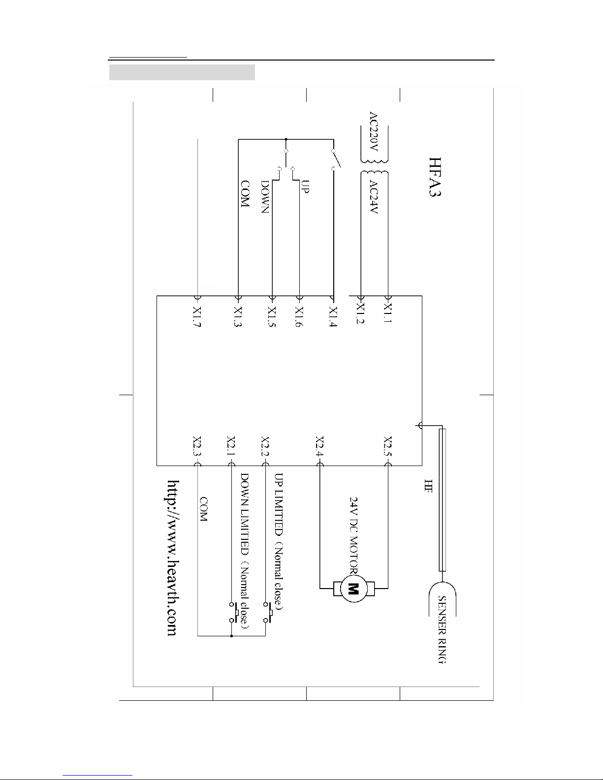
5 DRAWINGS AND DIAGRAMS
Collision Signal
AUTO/MANUAL(OPEN)
Page 14
HF100 CapecitanceHeightControler
http://www.heavth.com
第 - 14 - 页 共 14 页
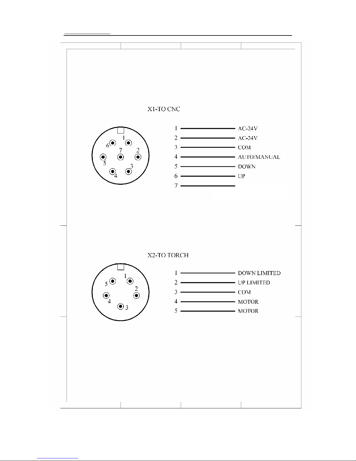
Collision Signal
 Loading...