

Page 1
C US
342 N. Co. Rd. 400 East
Valparaiso, IN 46383
219-464-8818 • Fax 219-462-7985
www.heatwagon.com
Installation and Maintenance Manual
Please retain this manual for future reference.
HVF110, 210, 310, 410HD
Construction Heaters
HVF110 for SN 21103001 and beyond
HVF210 for SN 21202501 and beyond
HVF310 for SN 21302501 and beyond
HVF410HD for SN 21801001 and beyond
For your safety: Do not use this heater in
a space where gasoline or other liquids
having flammable vapors are stored.
Revision 5-15
Page 2

CONSTRUCTION HEATER GENERAL HAZARD WARNING
TECHNICIAN.
WARNING
WARNING
WARNING
We cannot anticipate every use which may be made for our heaters. CHECK WITH YOUR
LOCAL FIRE SAFETY AUTHORITY IF YOU HAVE QUESTIONS ABOUT LOCAL REGULATIONS.
Other standards govern the use of fuel gases and heat producing products in specific applications. Your local authority can advise you about these.
FOR YOUR SAFETY
DO NOT USE THIS HEATER IN A SPACE WHERE GASOLINE OR OTHER
LIQUIDS HAVING FLAMMABLE VAPORS ARE STORED OR USED.
IMPORTANT
Heater is designed for use as a construction heater. Heater is not intended for use in pest
remediation. The primary purpose of construction heaters is to provide temporary heating of
buildings under construction, alteration, or repair and to provide emergency heat. Properly
used, the heater provides safe, economical heating. Products of combustion are vented outside the area being heated.
Page 3

Installation and Maintenance Manual
Model HVF110, 210, 310, 410HD
Construction Heater
Table of Contents:
Safety and Caution . . . . . . . . . . . . . . . . . . . . . . . . . . . . . . . . . . . . . . . . . . .2
Specifications . . . . . . . . . . . . . . . . . . . . . . . . . . . . . . . . . . . . . . . . . . . . . . .4
Installation . . . . . . . . . . . . . . . . . . . . . . . . . . . . . . . . . . . . . . . . . . . . . . . . .5
Operating Instructions . . . . . . . . . . . . . . . . . . . . . . . . . . . . . . . . . . . . . .5, 9
Maintenance . . . . . . . . . . . . . . . . . . . . . . . . . . . . . . . . . . . . . . . . . . . . . . . .5
Control Board . . . . . . . . . . . . . . . . . . . . . . . . . . . . . . . . . . . . . . . . . . . .6, 8
Troubleshooting . . . . . . . . . . . . . . . . . . . . . . . . . . . . . . . . . . . . . . .7, 11-17
HVF110 Wiring/Parts . . . . . . . . . . . . . . . . . . . . . . . . . . . . . . . . . . . . .18-20
HVF210 Wiring/Parts . . . . . . . . . . . . . . . . . . . . . . . . . . . . . . . . . . . . .21-23
HVF310 Wiring/Parts . . . . . . . . . . . . . . . . . . . . . . . . . . . . . . . . . .21, 24-25
HVF410HD Wiring/Parts . . . . . . . . . . . . . . . . . . . . . . . . . . . . . . . . . .26-28
Accessories . . . . . . . . . . . . . . . . . . . . . . . . . . . . . . . . . . . . . . . . . . . . . . . .29
Chimney/Flue Set-up . . . . . . . . . . . . . . . . . . . . . . . . . . . . . . . . . . . . . . . .31
WARRANTY
All new Heat Wagon and Sure Flame heaters and fans are guaranteed against defective materials and workmanship for one (1) year from invoice date.
Warranty repairs may be made only by an authorized, trained and certified Heat Wagon dealer. Warranty
repairs by other entities will not be considered. Warranty claims must include model number and serial
number.
LIMITATIONS
Warrant claims for service parts (wear parts) such as spark plugs, igniters, flame rods will not be allowed.
Diagnostic parts such as voltage meters and pressure gauges are not warrantable.
Evidence of improper fuel usage, fuel pressures outside of manufacturer’s specification, poor fuel quality,
and improper electric power, misapplication or evidence of abuse may be cause for rejection of warranty
claims.
Travel time, mileage and shipping charges will not be allowed. Minor adjustments of heaters are dealers’
responsibility. Defective parts must be tagged and held for possible return to the factory for 60 days from
date of repair. The factory will provide a return goods authorization, (RGA) for defective parts to be
returned.
No warranty will be allowed for parts not purchased from Heat Wagon.
342 N. Co. Rd. 400 East • Valparaiso, IN 46383
219-464-8818 • 888-432-8924 • Fax 800-255-7985
www.heatwagon.com
Page 4

HVF110 HVF210 HVF310 HVF410HD
1020
94.8
5.73
4.05
0.55-80º W
0.5
0.118
5.9
0.05
89.5
183.5
1.48
10.47
7.65
A=3.5, .196
5.9
0.05
294
2,531
88.0
258.7
2.17
15.37
1,330
11.80
174
A=4, .236
5.9
0.05
412/272
3250
354/231
2.89/1.86
1,820
20
2.0-80º W
160/218
0.6
1.5
5.90
0.05
17.2
49.3x20x33.3
142
27.7
56.5x21.9x38
220
Runs on: #2 diesel (winter blend)
#1 kerosene
35.7
56.5x21.9x38
297
57
83x33x48
456
4
Page 5

HVF 110, 210, 310
5
Page 6

HVF 110, 210, 310
A
B
Reset Button Room Thermostat Plug
Control Lamp Power Cord
Main Switch A-No Thermostat
B-With Thermostat
Regulation of Electrodes
6
HVF110
HVF210
HVF310
HVF410HD
Note: 1/16” = 1.6 mm
Page 7
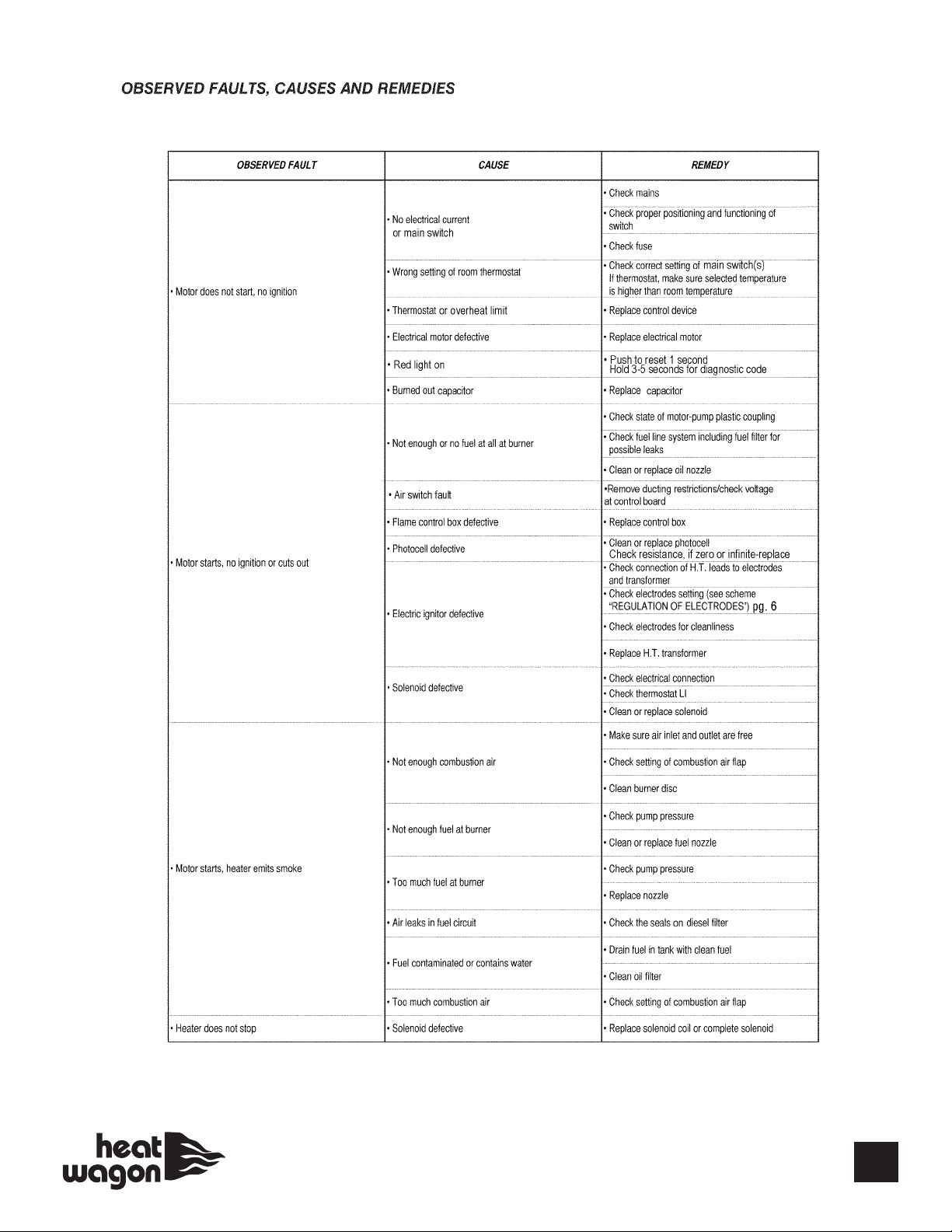
TroubeshooTing
For additional details see advanced troubleshooting (page 11).
7
Page 8
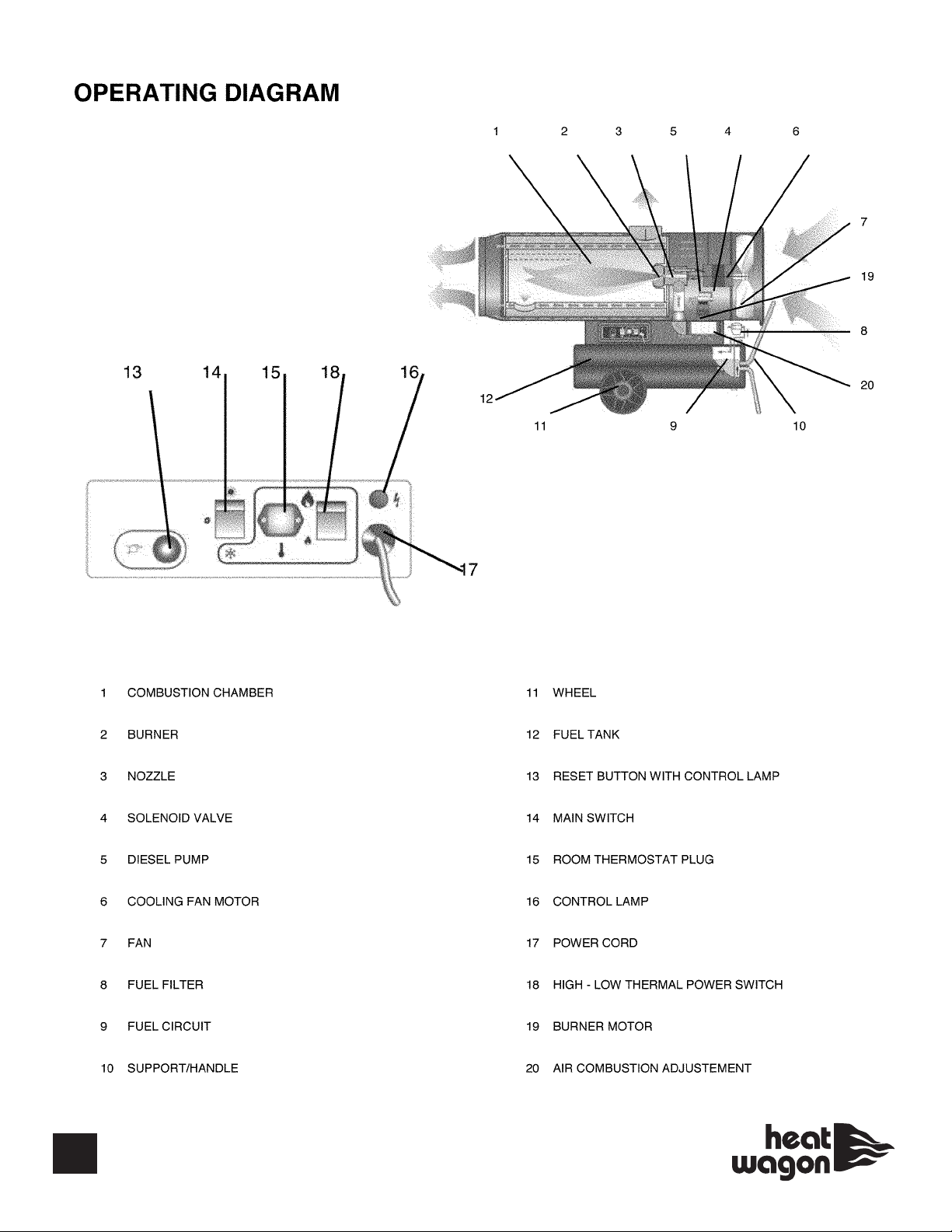
HVF 410HD
A
B
8
A-No Thermostat
B-With Thermostat
Page 9
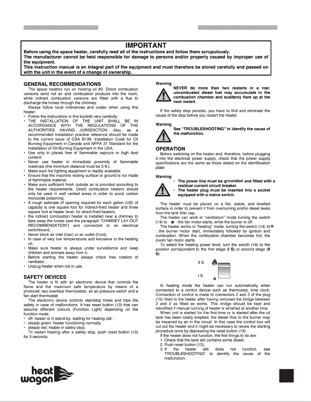
HVF 410HD
9
Page 10
HVF 410HD
10
Page 11

ADVANCED TROUBLESHOOTING
Motor and transformer do not operate.
Causes:
1. Incorrect or low voltage supplied to the heater.
2. Fuse in heater is blown. (no green light)
3. Thermostat defective, or not turned up to call for heat.
4. Control board is defective.
5. Reset button has not been reset. (red light on)
Solutions:
1. Incorrect or low voltage supplied to the heater. Most indirect oil heaters require a minimum of 108 volts to operate properly. A multi-meter set to
measure volts can be used to check the amount of voltage at the end of the extension cord(s). If the measured voltage is too low, the length of the
extension cord (s) must be shortened or a thicker gauge extension cord must be used.
2. Fuse in heater is blown. Locate and remove the in-line fuse of the heater. Set a multi-meter to measure ohms of resistance. Place a multi-meter
probe on each end of the fuse. The multi-meter should read zero ohms (continuity) or the fuse is blown. If a new fuse blows immediately, check for
possible causes. Check for incorrect voltage to the heater. Make sure the total amperage draw of all equipment running on the circuit is not too
great. If the supplied voltage and total amperage draw are correct, check the wiring in the heater for correctness and possible shorts.
3. Thermostat is defective or not turned up to call for heat. Turn the thermostat up to the highest possible setting and try to start the heater. Next
set a multi-meter to measure voltage coming out of the thermostat. If approximately 120 volts is not measured, the thermostat is defective.
4. Control board is defective. Using a multi-meter set for volts, check the hot and neutral wires which bring voltage into the control board. If proper
voltage is reaching the board then the control board is defective. Check fuse on control board.
*NOTE: Top cover shell of heater needs to be
attached during troubleshooting (will affect
operation of airswitch and photocell).
5. Reset button has not been reset. Push the reset button and try to start the heater.
Motor does not start, but ignition spark is present
Causes:
1. Control board is defective.
2. Motor is defective.
3. Motor start capacitor is defective.
4. Fuel pump seized
Solutions:
1. Control board is defective.Locate the terminals of the control board that connect to the motor wires. Use a multi-meter set to read voltage and
check for approximately 120 volts to the motor when the heater is turned on. If no voltage is observed the control board is defective. Check fuse on
control board.
2. Motor is defective. If the control board and the motor start capacitor check ok and the fuel pump is not seized, the motor is defective.
3. Motor start capacitor is defective. The capacitor may be tested using a multi-meter set to the lowest possible ohm range. First “short” the capacitor by momentarily placing a screwdriver across the two capacitor terminals. Then place the multi-meter probes on the two capacitor terminals. The
multi-meter should read close to zero ohms (continuity) first, then slowly move to infinity on the multi-meter. If not then the capacitor is defective.
4. Fuel pump seized. With the heater unplugged, stand behind the heater and attempt to turn the fan blade clockwise by hand. If the fan blade is
difficult to turn, undo the connection between the motor shaft and the pump shaft. Attempt turning the fan blade again. If the motor now turns freely,
the pump has seized up. If the fan blade is still difficult to turn, the motor is defective.
11
Page 12

Motor runs, no visible ignition and heater reset (red light) comes on
Causes:
1. Fuel filter is dirty.
2. Spray nozzle clogged.
3. Air proving switch defective.
4. Air entering the fuel pump thru the inlet line.
5. Safety thermostat defective or tripped.
6. Fuel pump is defective/or broken pump coupling
7. Solenoid valve is defective.
8. Control board is defective.
Solutions:
1. Fuel filter dirty. Check the external and internal fuel filters and clean or replace as necessary. Most fuel pumps contain an internal fuel filter
located where the inlet line enters the fuel pump.
2. Spray nozzle clogged. Remove and inspect the spray nozzle. Clean or replace as needed. Do not clean the nozzle orifice with anything metal
as this may enlarge the orifice.
3. Air proving switch is defective. Try to start the heater without ducting. Indirect oil heaters have an air proving switch wired between the control
board and the solenoid valve. The air proving switch is normally open and requires air from the turning fan blade to close the switch and send
power to the solenoid valve. Set a multi-meter to measure voltage. With the fan blade turning, check for voltage coming out of the air proving
switch to the solenoid valve. If no voltage is read, next check for voltage at the control board terminals out to the air proving switch. If voltage at the
control board is read, the air proving switch is defective. If no voltage is read at the board, the control board is defective.
4. Air entering the fuel pump thru the fuel inlet line. If air enters the pump it will lose its prime and will not maintain adequate pump pressure. First
make sure all fittings, including the fuel filter on the inlet line are tight. If you still suspect air is entering the pump, start eliminating portions of the
inlet line until the air leak is found. Start this process at the fuel tank end of the inlet line. It may be necessary to draw fuel from a small container
rather than the fuel tank.
5. Safety thermostat defective or tripped. Also called overheat switch. Some indirect oil heaters have a safety thermostat wired between the control board and the solenoid valve. If the heater becomes too hot this normally closed switch will open and interrupt power to the solenoid valve.
Use a multi-meter set to measure ohms. Place the multi-meter probes on the two male terminals of the safety thermostat. If the multi-meter shows
infinity (no continuity) the safety thermostat is defective. If the switch opens up before the heater becomes hot, the safety thermostat is defective.
6. Fuel pump is defective. The output pressure of the fuel pump can be checked by placing a high pressure fuel gauge into the gauge port of the
fuel pump. Use a gauge with enough capacity to measure the high pressure your particular heater can produce. Use the adjustment on the pump
to set the pump pressure to the manufacturer’s specification. If you do not have a fuel gauge, you may slightly loosen the pump’s output line connection and place a rag there. Run the heater briefly and see if fuel reaches the rag. If no fuel is pumped, check the connection between the motor
and the fuel pump to make sure the motor can turn the pump. Also check the external and internal fuel filters for blockage, and clean or replace if
necessary. The fuel pumps internal filter is usually located where the fuel inlet line enters the pump. Check to make sure motor is rotating pump.
7. Solenoid valve is defective. Call tech service for assistance.
8. Control board defective. Use a multi-meter set to measure voltage. Take a voltage reading on the control board terminals that send input power
to the transformer. If proper voltage is not present, the control board is defective. Check fuse on control board.
12
Page 13

Motor runs, fuel sprays, but no spark is observed
Causes:
1. Electrodes damaged or gapped incorrectly.
2. Transformer defective.
3. Control board defective.
Solutions:
1. Electrodes damaged or gapped incorrectly. Inspect the electrode tips for melting. Make sure there are no cracks in the porcelain insulation.
Check the electrodes with the manufacturer’s specifications for gapping and spacing. Adjust or replace the electrodes as needed.
2. Transformer defective. Transformers require a ground connection to function properly. Check the transformer’s ground wire or mounting tabs for
a good ground connection. Use a multi-meter set to measure voltage. Check the voltage in to the transformer from the control board for approximately 120 volts. Do not attempt to measure the transformer’s output voltage with an ordinary multi-meter. The transformer may also be bench
tested for proper output arc.
3. Control board defective. Use a multi-meter set to measure voltage. Take a voltage reading on the control board terminals that send input power
to the transformer. If proper voltage is not present, the control board is defective. Check fuse on control board.
Motor runs, fuel sprays, spark is present, but heater will not ignite
Causes:
1. Pump pressure incorrect.
2. Electrodes damaged or gapped incorrectly.
3. Nozzle dirty or worn.
4. Air damper setting is incorrect.
5. Transformer output is weak.
6. Ducting is improper.
7. Venting is improper.
8. Fuel contains water or contaminants.
Solutions:
1. Pump pressure incorrect. Using a high pressure fuel gauge, check the output pressure of the fuel pump. If necessary, use the pump’s adjustment to set the pump pressure to the manufacturer’s specifications.
2. Electrodes damaged or gapped incorrectly. Inspect the electrode tips for melting. Make sure there are no cracks in the porcelain insulation.
Check the electrodes with the manufacturers specifications for gapping and spacing. Adjust or replace the electrodes as needed.
3. Nozzle dirty or worn. Clean the nozzle using compressed air. Never use anything metal to clean the nozzle as this may enlarge the orifice. With
enough use, fuel traveling under high pressure thru the nozzle orifice can enlarge the orifice. This is especially true when diesel fuel is used. Clean
or replace the nozzle as needed.
4. Air damper setting is incorrect. Use the manufacturers specifications for the air damper setting and adjust as needed.
5. Transformer output is weak. Remove the transformer and perform a bench test.
6. Ducting is improper. Follow the manufacturer’s recommendations concerning maximum duct length and diameter.
7. Venting is improper. Follow the manufacturer’s guidelines for venting.
8. Fuel contains water or contaminants. Visually inspect the fuel in the tank for water bubbles or contaminants. Drain, flush, and re-fill tank as
needed.
13
Page 14

Heater ignites, runs less than one minute and shuts down
Causes:
1. Photocell is dirty, misaligned or defective.
2. Control board is defective.
3. Fuel pump defective.
4. Fuel filter dirty.
Solutions:
1. Photocell is dirty, misaligned or defective. Check that the photocell is aimed correctly and is free of dirt. If necessary, clean the photocell “eye”
with a soft, dry cloth. If resistance is zero or infinite, photocell is defective.
2. Control board is defective. If the heater’s spray and spark are correct, the photocell and control board must work together to recognize the combustion flame has become established. Therefore if a new photocell does not correct this symptom, the control board is defective.
3. Fuel pump is defective. If the fuel pump will not achieve or maintain proper output pressure, the fuel pump is defective. Check the pump’s output
pressure with a gauge.
4. Fuel filter dirty. Inspect the internal and external fuel filters and clean or replace as needed.
Heater ignites, runs several minutes, then shuts down.
Causes:
1. Fuel pump is defective.
2. Overheat thermostat is defective.
3. Ducting is improper.
4. Venting is improper.
5. Nozzle is dirty.
6. Fuel filter is dirty.
7. Control board is defective.
8. Fuel contains water or contaminants.
9. Solenoid valve is defective.
Solutions:
1. Fuel pump is defective. If the fuel pump will not achieve or maintain proper output pressure, the pump is defective. Check the fuel pump output
pressure with a gauge.
2. Solenoid valve is defective. Use a multi-meter set to measure voltage. Check for proper voltage at the solenoid valve. If proper voltage is read
and the solenoid valve will not stay open and allow fuel spray, the solenoid valve is defective.
3. Overheat thermostat is defective. Also called a safety thermostat or limit switch. Some heaters are equipped with this. Set a multi-meter to measure ohms of resistance. Perform this test immediately after the heater shuts down and the overheat thermostat is still hot. Place the multi-meter
probes on the two male terminals of the safety thermostat. If the multi-meter reads infinity (no continuity) the safety thermostat is defective.
Remember that if the heater is over firing due to high pump pressure, worn nozzle, or is improperly ducted or vented, the safety thermostat will
heat enough to shut the heater off.
4. Ducting is improper. Always follow the manufacturer’s recommendations
regarding maximum duct length and diameter. Failure to do so can result in heat building up in the heater until the safety thermostat contacts open
and shut the heater off.
14
Page 15

5. Venting is improper. Follow the manufacturer’s recommendations concerning proper venting. Failure to do so can result in heat building up in the
heater until the safety thermostat contacts open and shut the heater off.
6. Nozzle is dirty. If dirt reaches the nozzle, the spray can be adversely affected and cause a shut down. If possible observe the spray pattern and
clean the nozzle as needed.
7. Fuel filter dirty. Check the internal and external fuel filters. Clean or replace as needed.
8. Control board is defective. For the heater to function, the control board must send proper voltage to three components: motor, transformer and
solenoid valve. Using a multi-meter set to measure voltage, check the appropriate control board terminals for proper voltage out to these three
components. If proper voltage to any of these three components is not observed, the control board is defective.
9. Fuel contains water or contaminants. Visually inspect the fuel in the tank for water bubbles or contaminants. Drain, flush, and re-fill as needed.
Heater ignites, but combustion is poor or uneven
Causes:
1. Fuel pump pressure is incorrect.
2. Nozzle dirty or worn.
3. Electrodes damaged or gapped incorrectly.
4. Fuel filter is dirty.
5. Air damper setting incorrect.
6. Whirl disk dirty or mis-aligned.
7. Ducting is improper.
8. Venting is improper.
9. Fuel contains water or contaminants.
Solutions:
1. Fuel pump pressure is incorrect. The output pressure of the fuel pump can be checked by placing a high pressure fuel gauge into the gauge port
of the fuel pump. Use a gauge with enough capacity to measure the high pressure your particular heater can produce. Use the adjustment on the
pump to set the pump pressure to the manufacturer’s specifications.
2. Nozzle dirty or worn. Clean the nozzle using compressed air. Never use anything metal to clean the nozzle as this may enlarge the orifice. With
enough use, fuel traveling under high pressure thru the nozzle orifice can enlarge the orifice. This is especially true when diesel fuel is used. Clean
or replace the nozzle as needed.
3. Electrodes damaged or gapped incorrectly. Inspect the electrode tips for melting. Make sure there are no cracks in the porcelain insulation.
Check the electrodes with the manufacturer’s specifications for gapping and spacing. Adjust or replace the electrodes as needed (page 5/17).
4. Fuel filter is dirty. Inspect the internal and external fuel filters and clean or replace as needed.
5. Air damper setting incorrect. Use the manufacturer’s specifications for the air damper setting and adjust as needed. (see Diagram B, page 17)
6. Whirl disk dirty or mis-aligned. Inspect the whirl disk and clean if necessary. If the disk is warped or mis-aligned, replace or adjust as needed.
7. Ducting is improper. Follow the manufacturer’s recommendations concerning maximum duct length and diameter.
8. Venting is improper. Follow the manufacturer’s guidelines for venting.
9. Fuel contains water or contaminants. Visually inspect the fuel in the tank for water or contaminants. Drain, flush, and re-fill tank as needed.
15
Page 16

Heater ignites but flame is excessive
Causes:
1. Fuel pump pressure is too high.
2. Nozzle is worn.
3. Incorrect fuel.
Solutions:
1. Fuel pump pressure is too high. Attach a high pressure fuel gauge to the fuel pump and check the pump pressure. Adjust the pressure to the
manufacturer’s specifications with the adjustment on the fuel pump.
2. Nozzle is worn. With enough use, the impurities in the fuel traveling under high pressure thru the nozzle orifice can enlarge the orifice. This is
especially true when diesel fuel is used. A worn nozzle can cause the heater to run “rich” and possibly over fire the heater enough to activate the
safety thermostat and cause a shutdown. Replace after 400 hours of operation.
3. Incorrect fuel. Only use the manufacturer’s recommended fuels. Never use gasoline, paint thinner, solvents, or other flammable liquids. If you
suspect the fuel is incorrect, drain, flush and re-fill the tank with proper fuel.
FUEL PUMP ADJUSTMENT
1.10
1.50
80º W
80º W
80º W
12 / 174
2 Stage
P1: 10/145
P2: 20 / 290
P1: 160
P2: 218
1 Stage
12 / 174
16
Page 17
1.
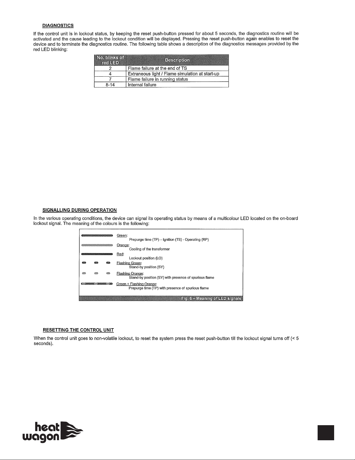
FOR 2 RED BLINKS CAUSE MAY BE:
• No flame at 1st start up (review page 12 and 13)
• Other causes may be defective over heat limit switch (check for continuity)
FOR 4 RED BLINKS CAUSE MAY BE:
• Photocell senses light before start- up (make sure cover is on and photocell installed properly)
FOR 7 RED BLINKS CAUSE MAY BE:
• Out of fuel
• Filter or nozzle blocked
• Broken fuel line (intake sucking air)
• Bad photocell
• Overheat limit switch tripped
2.
3.
• Non-volatile lockout (manual reset), in order to reset the system, the reset button must be pressed (less than 5 seconds).
• Volatile lockout, hold reset button for a least one minute, red light should go out, let control board “reboot” for at least
another minute before attempting to start again.
17
Page 18
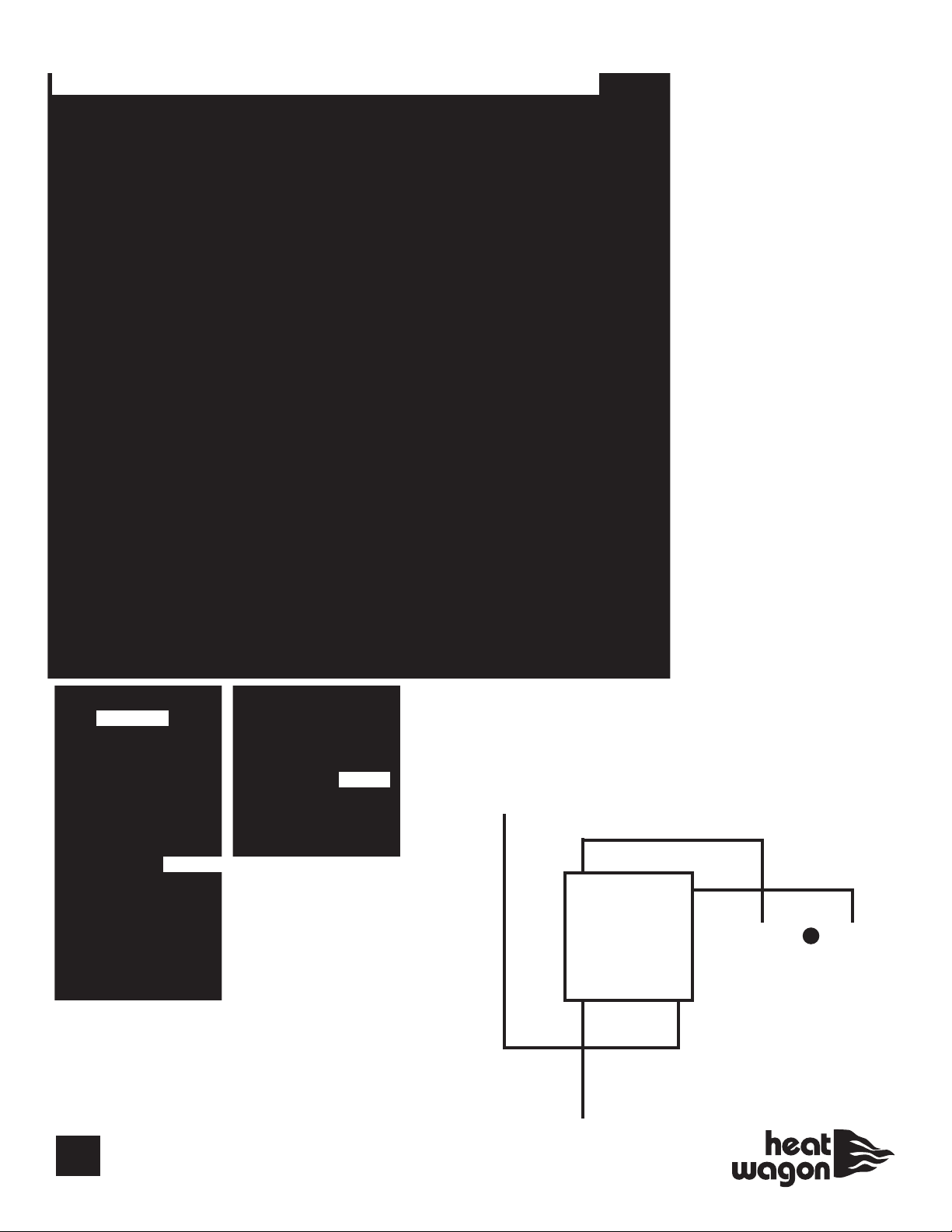
HVF110 Electrical Schematic
For SN 21103001 and Beyond
18
P/N - E10325
(CAPACITOR)
SWITCH
RV3 (110)
RV1 (210,310)
RV (410)
Wiring Schematic For
Digital Thermostat
3
2 1
RV1 (110)
RV3 (210,310)
Term #2 on Brahma (410)
G
L
(Hot)
N
ST
Page 19
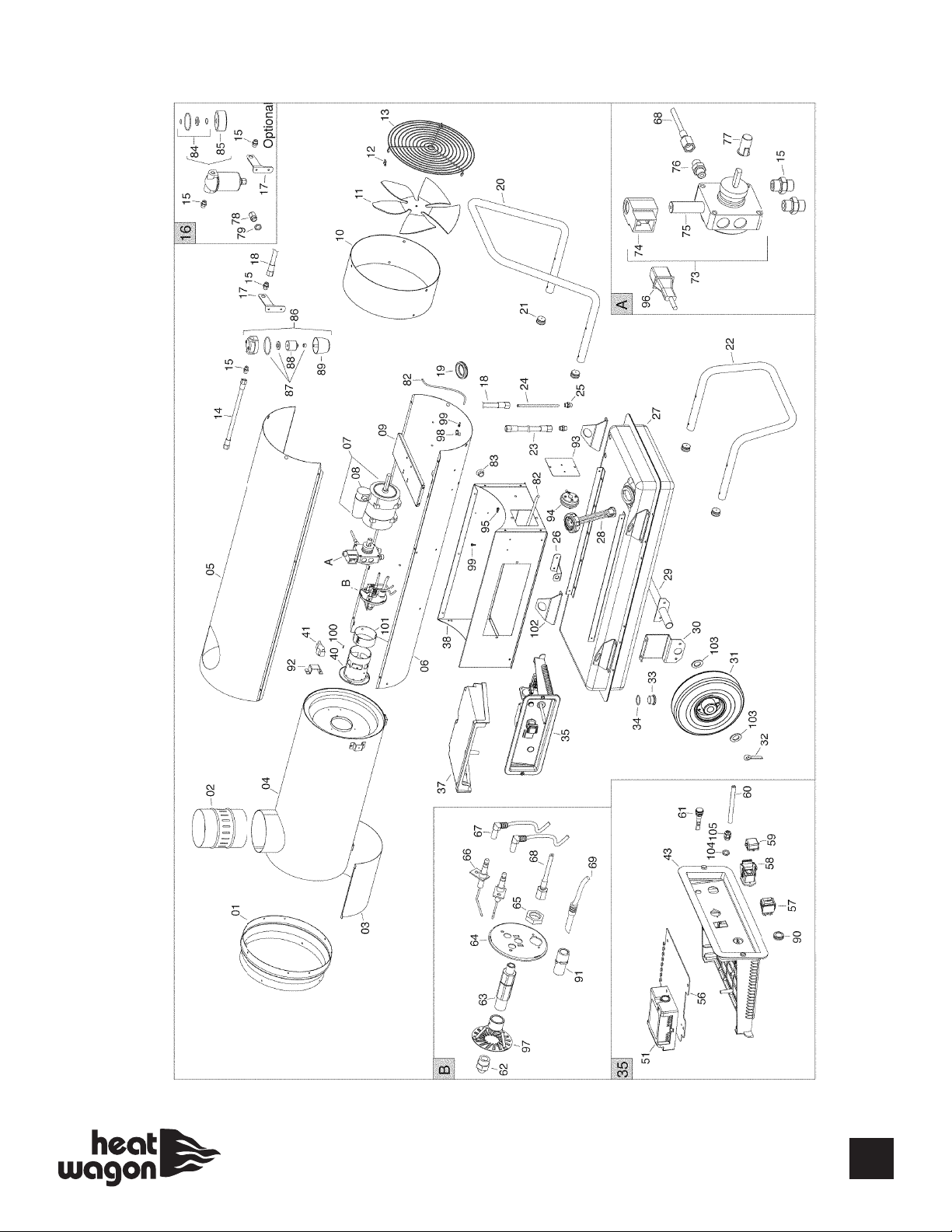
HVF110 Breakdown
For SN 21103001 and Beyond
19
Page 20
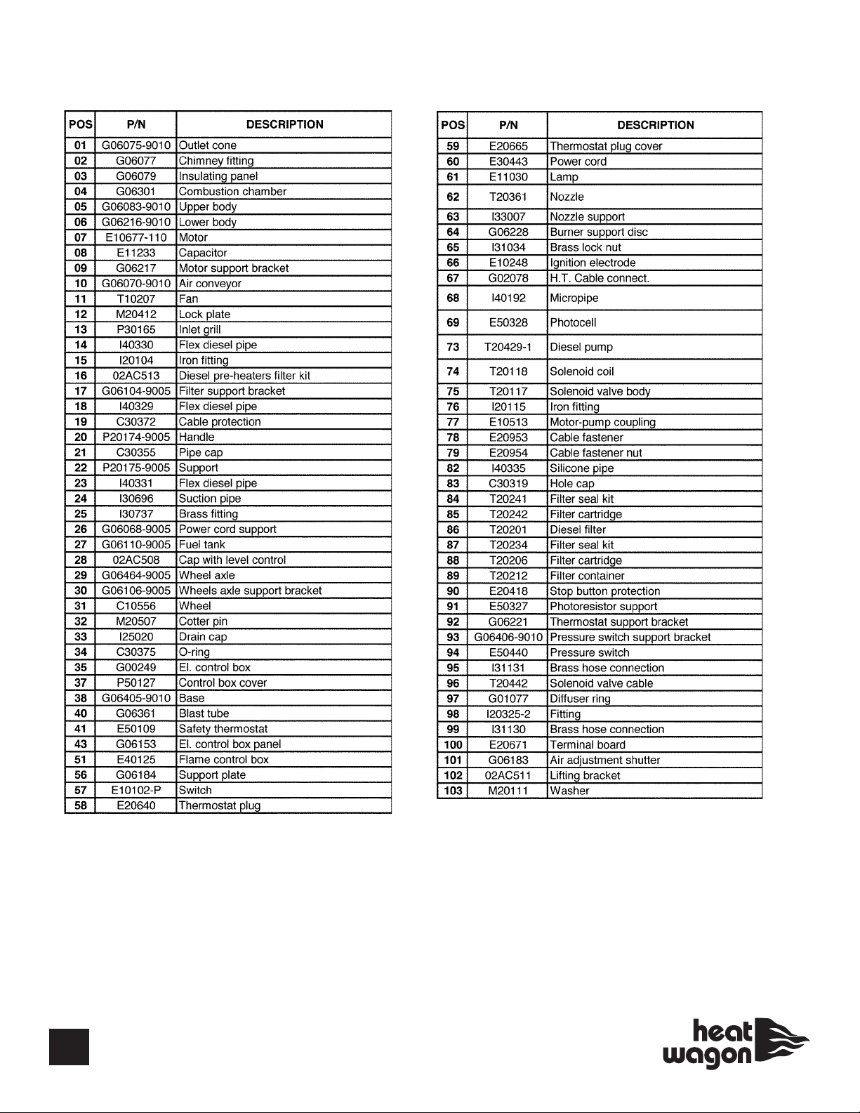
HVF110 Parts List
For SN 21103001 and Beyond*
20
* Note for S/N Starting 21105001
POS P/N DESCRIPTION
07 E10770 Motor
08 E10770-1 Capacitor
60 E30443-1 Power cord
77 E10698 Motor pump coupling
104 E20965 Cable fastener nut
105 E20964 Cable fastener
Page 21

HVF210 Electrical Schematic for SN 21202501 and Beyond
HVF310 Electrical Schematic for SN 21302501 and Beyond
(CAPACITOR)
P/N - E10325
21
Page 22
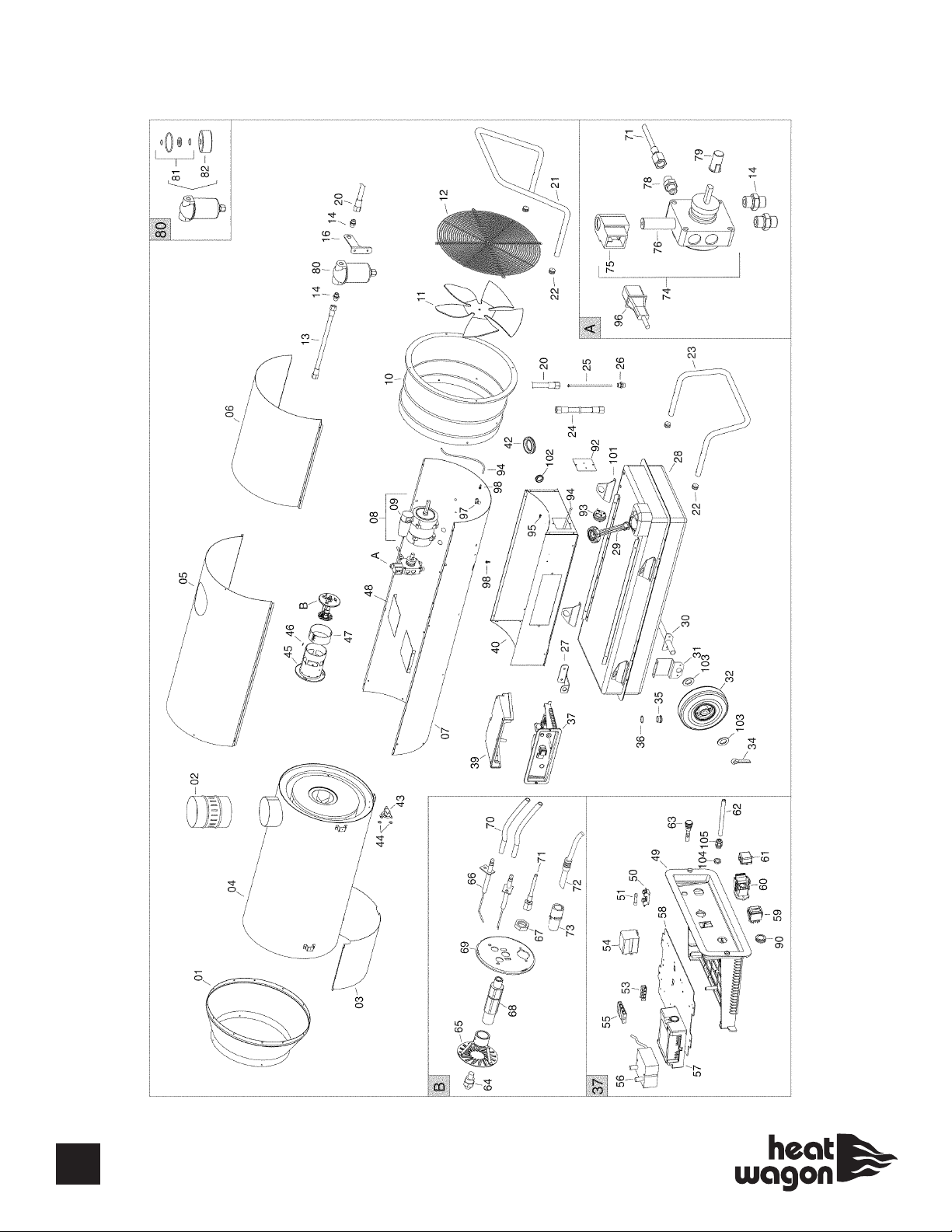
HVF210 Breakdown
For SN 21202501 and Beyond
0-102
22
Page 23
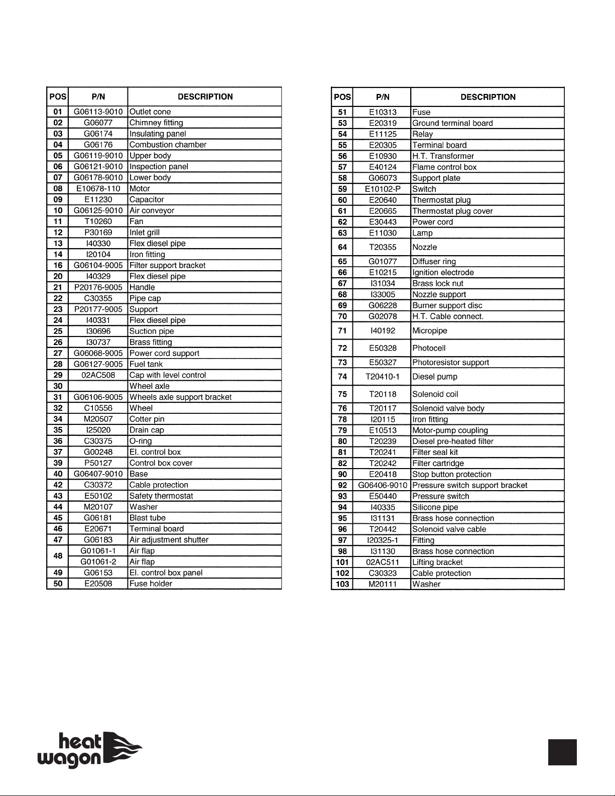
HVF210 Parts List
For SN 21202501 and Beyond*
G06464-9005
* Note for S/N Starting 21204001
POS P/N DESCRIPTION
08 E10771 Motor
09 E10771-1 Capacitor
62 E30443-1 Power cord
79 E10698 Motor pump coupling
104 E10965 Cable fastener nut
105 E10964 Cable fastener
23
Page 24
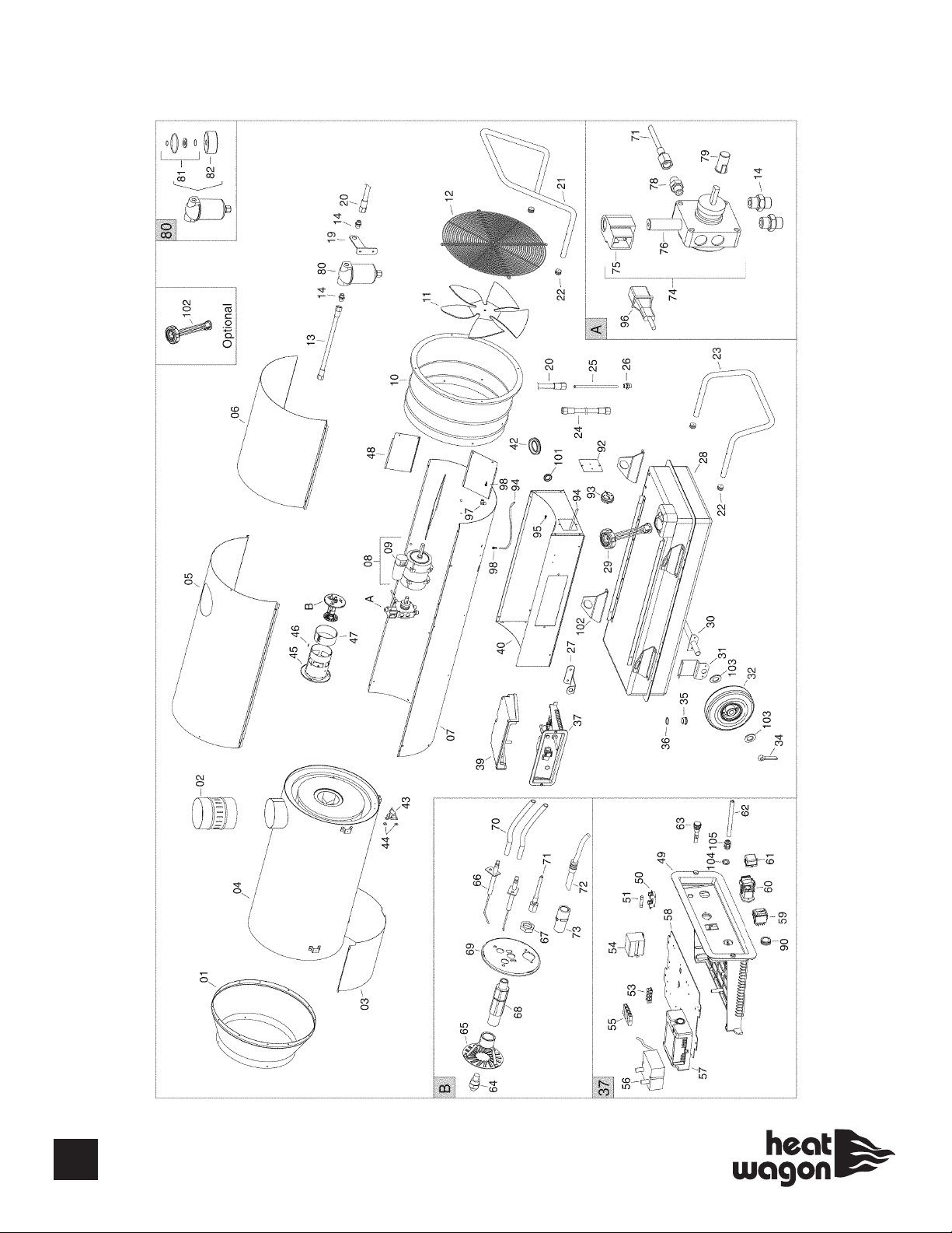
HVF310 Breakdown
For SN 21302501 and Beyond
24
Page 25
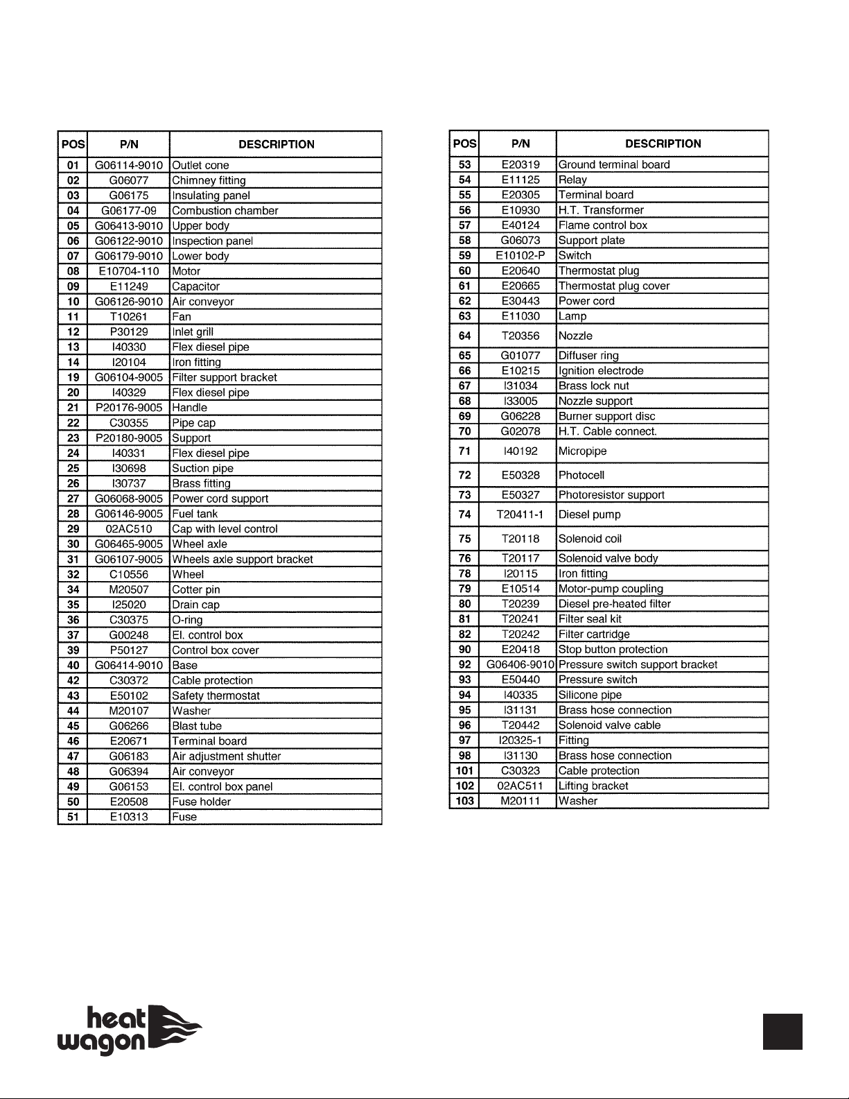
HVF310 Parts List
For SN 21302501 and Beyond*
* Note for S/N Starting 21304001
POS P/N DESCRIPTION
08 E10772 Motor
09 E10772-1 Capacitor
62 E30443-1 Power cord
79 E10698 Motor pump coupling
104 E20965 Cable fastener nut
105 E20964 Cable fastener
25
Page 26
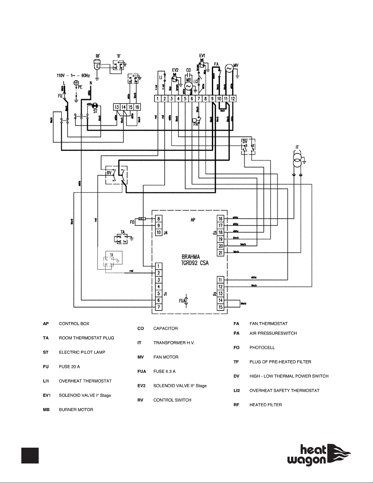
HVF410HD Electrical Schematic
SN 21801001 and Beyond
26
P/N - E10325
Page 27
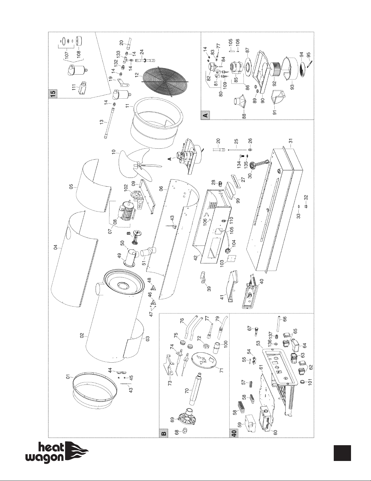
HVF410HD Breakdown SN 21801001 and Beyond
27
Page 28
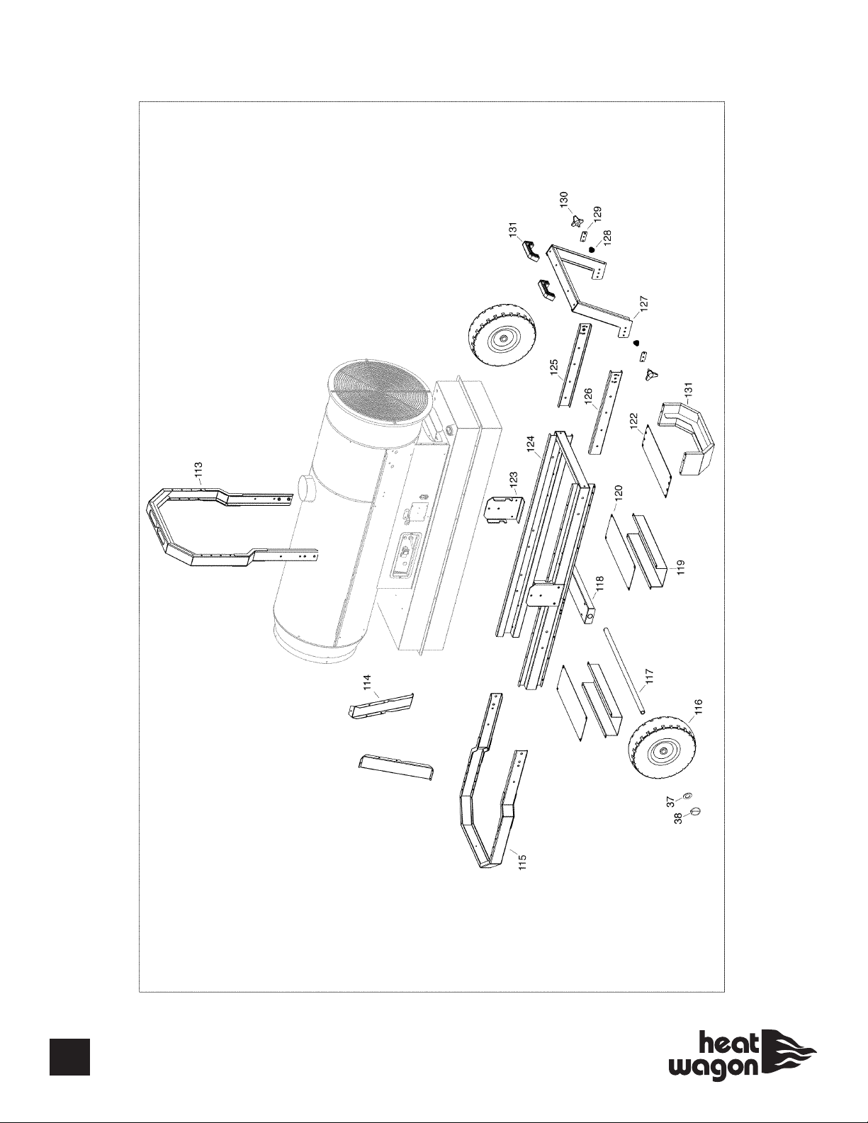
HVF410HD Breakdown SN 21801001 and Beyond
28
Page 29

HVF410HD Parts List SN 21800800 and Beyond*
* Note for S/N Starting 21801001
POS P/N DESCRIPTION
07 E10772 Motor
08 E10772-1 Capacitor
84 E10698 Motor pump coupling
85 E10770-1 Capacitor
86 E10770 Motor
136 E20965 Cable fastener nut
137 E20964 Cable fastener
29
Page 30

Accessories
THERMOSTAT
#THIDF
DUCT ADAPTERS (ONE WAY)
HVF110 #AR110
HVF210 #AR210
HVF310 #AR310
HVF410HD #AR401
EXTERNAL FUEL KIT
(allows access to
external fuel source)
#TK300
DUCTING
HVF110 - #WD1225 (12”X25’)
HVF210 (2 WAY) - #WD1225 (12”X25’)
HVF310 (2 WAY) - #WD1225 (12”X25’)
HVF210 (1 WAY) - #WD1425 (14”X25’)
FUEL CADDY (28 GALLONS)
#PFC28
DUCT ADAPTERS (TWO WAY)
HVF210 #AR212
HVF310 #AR312
HVF410HD #AR402
30
FLUE STACK
#EF1
HVF310 (1 WAY) - #WD1825 (18”X25’)
HVF402 (2 WAY) - #WD1825 (18”X25’)
HVF410HD (1 WAY) - #WD2025 (20”X25’)
FUEL PRESSURE GAUGE
#BIE99AM003
Page 31

31
Page 32

342 N. Co. Rd. 400 East
Valparaiso, IN 46383
219-464-8818 • Fax 219-462-7985
www.heatwagon.com
 Loading...