

Heat Transfer SSV90-45S, SSV199-45S, SSV130-45R, SSV130-45S, SSV130-80R Operating, Installation And Service Manual
...
t
r
oema
ANSI Z 21.10.3
MANUFACTUREDBY: HEAT TRANSFER PRODUCTS, INC
P O BOX429, 120 BP,ALEY ROAD
EAST FREETOWN, MA 02717
TEL.:
FAX."

I ,m tur. rren
Series BTU U.S. Tamp. Wa_. aas peII(DegreesFahrenhelt)A=6yrs. parts; t) yrs. €omm.;10 yrs. rea.
R = 160 B = 1 yr. parts; 3 yrs. comm.; 10 yrs. res.
Gal. (Deg. II s=
130 _'- 45
GALLON INPUT BTU/I'IR. _ TEMPERATURE RISE IN DEGREES FAHRENHErr
MODEL CAPACITY NATURAL & LP GAS _ 40 50 60 70 80 90 100 110 120 130 140
GPH 545 436 363 311 272 242 218 198 181 167 155
_SV199-119R 119 199T000 GPM 9 7 6 5 4 5 4 3 5 3 3 3 2.7 2 5
GPH 545 436 363 311 272 242 218 198 181 167 155
3SV & SSVH199-80R 80 199r000 GPM 9 7 6 5 4 5 4 3 5 3.3 3 2.7 2.5
GPH 545 436 363 311 272 242 218 198 181 167 155
SSV199-45S 45 199r000 GPM 9 7 6 5 4.5 4 3 5 3 3 3 2 7 2 9
GPH 436 349 290 249 218 193 174 158 145 134 124
SSV160-45S 45 160_000 GPM 7 5 8 4 8 4 3 6 3 2 2 9 2 6 2.4 2.2 2
._ GPH 354 283 236 202 177 157 141 128 118 109 101
3SV130-SOR 80 130,000 GPM 59 47 39 3.9 29 2.6 23 21 19 18 16
GPH 354 283 236 202 177 157 141 128 118 109 101
SSV130-119R 19 1301000 GPM 59 4.7 39 3,9 2.9 26 2.3 2,1 1.9 1 8 1,6
GPH 354 283 236 202 177 157 141 128 118 109 101
SSV130-45RiS 45 130r000 GPM 5 9 4 7 3.9 3.9 2.9 2 6 2 3 2 1 1.9 1.8 1 6
GPH 354 283 236 2()2 177 157 141 128 118 109 101
SSVH130-45S 45 130_000 GPM 5 9 4.7 3.9 3 9 2.9 2.6 2,3 2.1 1.9 1.8 1 6
GPH 269 215 179 154 134 119 108 98 89 82 77
SSV100-45R 45 100r000 GPM 4.4 35 2.9 25 2.2 1 9 1.7 1,5 1 4 1 3 1.2
, GPH 245 196 163 140 122 109 98 89 81 75 70
SSV90-45S _._ 45 _ 9Or000 GPM 4 3,2 2.7 2.3 _ _°2 1.8 1 6 1,4 1 3 12 1 1
o_- • - _ GPH 245 196 163 140 122 109 98 ,I 89 81 75 70
SSVHg0-45S 45 90r000 GPM 4 3.2 2.7 2 3 2 1 8 1 6 1.4 1.3 1.2 1.1
Recovery on rating plate Is based at 94% thermal efficiency at 100 degrees Fahrenheit rise, as required by A.N.S.I.
FIRST HOUR
"RATING
,300
o _ 270 o_
_250 o
-'_220 ,
• t80
- ._125
WARNING_:
IF THE INFORMATION IN THESE INSTRUCTIONS ARE NOT FOLLOWED EXACTLY, A FIRE OR EXPLOSION MAY
RESULT; CAUSING PROPERTY DAMAGE, PERSONAL INJURY, OR DEATH.
Do not store or use gasoline or other flammable vapors and liquids in the vicinity of this or any other appliance;
WHAT TO DO IF YOU SMELL GAS:
Do not try to light any appliance;
Do not touch any electrical switch; do not use any phone in your building;
Immediately call your gas supplier from a neighbor's phone;
Follow the gas supplier's instructions;
If you cannot reach your gas supplier; call the fire department;
Installation and service must be performed by a qualified installer; service agency or the gas supplier.
DANGER:
Water temperature over 125 degrees F. can cause severe bums instantly, or death from
_(_llm_ _-_ scalds. Children, disabled, and eldedy are at highest risk of being scalded. See _(_
_._-_ _'€*'_ instruction manual before setting temperature at water heater. Feel water before _
bathing or showering! Temperature limiting valves are available.
LOCATION
Choose a location for your water heater centralized to the piping system, along with consideration to vent pipe length. As the length of
vent pipe increases the firing rate of the appliance decreases. You must also locate the Voyager where it will not be exposed to freez-
ing temperatures. Additionally, you will need to place the water heater so that the controls, drain, inlet/outlet, and gas valve are easily
accessed. This appliance must not be installed outdoors, as it is certified as an indoor appliance, and must be kept vertical and on a
level surface. Also, care must be exercised when choosing the location of this appliance; where leakage from the relief valve, leakage
from related piping, or leakage from the tank or connections, will not result in damage to the surrounding areas or to the lower floors of
the building. A water heater should always be located in a area with a floor drain or installed in a drain pan suitable for water
heaters. Proper clearance must be provided around the Voyager as follows: Sides, bottom, top, and back are 0" (zero clearance).
Front of the appliance needs 24" service clearance minimum. This front service may be achieved by a non-rated or combustible door
or access panel; providing the 24" service clearance is achieved when the door is opened or panel is removed. Under no circum-
stances, shall Heat Transfer Products Inc. be held liable for any such water damage whatsoever. This water heater must not
be located near flammable liquids such as gasoline, adhesives, solvents, paint thinners, butane, liquefied propane, etc.; as
the controls of this appliance could ignite those vapors, causing an explosion.
TEMPERATURE AND PRESSURE RELIEF VALVE
A temperature and pressure relief valve is installed into the marked port (upper right), we recommend a WATTS 100XL-4 valve or
equivalent for 100,000 BTU models or below input, 40XL5 valve or equivalent for 130,000 BTU models or above input, meeting the
requirements for relief valves for hot water heaters as per ANSI Z21.22B-1984 by a nationally recognized lab that maintains a periodic
inspection of production of such listed safety device. The pressure rating of the valve must not exceed the listed working pressure of
this appliance, and must be rated to the proper BTU/hr capacity of the water heater. Do not, under any circumstances, thread s cap
or plug into the relief valvel Explosion, serious injury or death may resultl Relief valve piping must be directed to the floor or to
an open drain, but not connected directly. There must be a 6" space between the outlet of relief valve piping and drain or floor. Do not
hook up to drain system directly without an air space. The relief valve must be periodically checked for proper operation.
PAGE:3 LP41 RE_: 1_1_

EXPANSIONTANK
Apotablehotwaterexpansiontankmaybe required to offset the water expansion as the water is heated. In most city plumbing sys-
tems, the water meter has a no return or back flow device built into the system to prevent back flowing of water back into city mains.
Some require back flow preventers on all incoming water supplies. Under these circumstances, you will need a hot water expansion
tank listed for potable water use. The expansion tank should be located on the cold inlet piping close to the water heater. The expan-
sion tank must be suitable for hot potable water.
DOMESTIC WATER CONNECTIONS
The domestic water connections must be installed in accordance to all local and national plumbing codes, or any applicable standard
which prevails. NEVER USE DIELECTRIC UNIONS OR GALVANIZED STEEL FITTINGS ON VOYAGER CONNECTIONS. The inlet
and outlet ports of the Voyager are t" on 45 gallon models. On the 80 and 119 gallon models, the inlet and outlet ports are 1 V2". On
the cold inlet, (bottom left), install a 1" brass tee on 45 gallon models, or a 1 1/2"tee on 80 and 119 gallon models. On the run of the 1"
brass tee, install with pipe sealant compound, a 1" brass drain cock or equivalent. Into the branch of the 1" or a 1 1,_,,brass tee, install
a copper male adapter to match your copper plumbing system. For convenience, you may install a sweat shut off valve and a union in
the cold inlet piping to ease servicing in the future. If there is a back flow preventer, or any type of a no return valve in the system, then
you must install an additional tee here for a suitable potable hot water expansion tank. In the hot outlet, (top left), install a suitable
adapter to match the copper tubing of the plumbing system. A thermal trap or heat trap loop may be installed here, to provide addition-
al energy savings and prevent the thermal siphoning of domestic hot water. Refer to _ for typical installations. A domes-
tic hot water tempering/anti-scald valve should be installed into hot water line to prevent the maximum outlet water temperature from
exceeding 119 degrees F. as per the national standard plumbing code, to prevent scald injury.
ELECTRICAL CONNECTION
The electrical connection for the Voyager is on the left side of the combustion shroud. There is a 1/2" knockout location for electrical
connection. All electrical wiring must be performed by a qualified licensed electrician, and in accordance with National Electrical Code,
or to the applicable local codes and standards. The electrical requirements are for standard 120 volts, 60 Hz 10 amp service. It is rec-
ommended that an electrical disconnect switch be placed on a nearby wall, and that the connection to the Voyager be made using 3/8"
extra-flex, or 3/8" greenfield (or equivalent). This unit must be wired with #14 awg, and fused for no more than 15 amps. It is of
extreme imoortance that this unit be Drooerlv oroundedl Ground the water heater, by connecting the green wire in the electri-
cal access compartment, directly to the main building ground system. It is very important that the buildin_o svatem ground is
inspected bv a aualified electrician, erior to makina_ this connection. The black wire is the hot lead and the white wire is the
neutral lead. Once all connections have been made the electrical access may be closed. It is very_imoortant that the electri-
cal Dower is not turned on at this timer A green LED is provided on the main control board. This LED must be luminated
when appliance is turned on for proper operation. Failure to luminate means bad or missing ground or reverse polarity.
GAS CONNECTION
Gas supply shall have a maximum inlet pressure of less than 14" water column (350 mm), 1/2 pound pressure (3.4 kPa), and a mini-
mum of 7" water column. The entire piping system, gas meter, and regulator must be sized propedy to prevent pressure drop greater
than 0.5" as stated in the National Fuel Gas Code. This information is listed on the rating plate. It is very important that you are
connected to the type of gas as noted on the rating plate. "LP" or liquefied petroleum, or propane gas; or "Nat" natural gas or city
gas. All gas connections must be approved by the local gas supplier, or utility inaddition to the governing authority, prior to turning the
gas supply on. The nipple provided is 1/2", and it is mandatory that a 3/4" to 1/2" reducing bushing (provided) is used, threaded into
the branch of a 3/4" tee, and a drip leg fabdcated, as per the national Fuel Gas Code. You must ensure that the entire gas line to
the connection at the Voyager is no smaller than 3/4". Once all the inspections have been performed, the piping must be leak test-
ed. If the leak test requirement is a higher test pressure than the maximum inlet pressure, you must isolate the Voyager from the gas
line. Inorder to do this, you must disconnect the union and cap the inlet gas line. In the event the gas valve is exposed to a pressure
greater than 1/2 PSI, 14" water column, the gas valve must be replaced. Never use an oeen flame (lit match, liohter_ to check ass
PAGE: 4 LP-41 REV.: 12/16/98

GAS CONNECTION(CONTINUED)
Failure to follow all orecautlons could result in fire. exclosion or death! It is recommended that a soapy solution be used to
detect leaks. Bubbles will appear on pipe to indicate a leak is present. The gas piping must be sized for the proper flow and length of
pipe, to avoid pressure drop. Both the gas meter and the gas regulator must be properly sized for the total gas load. If you experience
a pressure drop greater than 1" WC, the meter or regulator or gas line is undersized or in need of service. On the inlet side of the gas
valve, there is a 1/8" NPT plug, which can be removed to attach a hose barb, hose, and inches of water column meter. Also, you can
attach a meter to the incoming gas drip leg, by removing the cap and installing the meter. The gas pressure must remain between 7"
and 14" during stand-by and unit running heat cycle. If an in-line regulator is used, it must be a minimum of 10 feet from the Voyager.
It is very important that the gas line is properly purged by the gas supplier or utility. Failure to properly purge the lines or
improper line sizing, will result in the failure of the Voyager lighting off. This problem is especially noticeable in NEW LP installa-
tions, and also in empty tank situations. This can also occur when a utility company shuts off service to an area to provide mainte-
nance to their lines. The gas valve is a special gas valve which has a Pressure Augmented Regulator feature, as well as negative out-
let pressure. This valve must not be replaced with a conventional valve under any circumstances. Make sure valve is in the "OFF"
position prior to turning gas supply on. As an additional safety feature, this valve has a left hand thread on the outlet end, and a special
tamper resistant electrical connector.
VENTING
FOR ALL MODELS 3" VENTED.EXCEPT SSV1OO-45R AND SSV130-45R (WHICH ARE 2" VENTED)
(FOR 2" VENTED MODELS SSV1O0-45R AND SSV13O-45R, SEE TOP OF PAGE 8)
For inlet air supply, top pipe on the right of the shroud, use 3" PVC schedule 40. It is very important that you plan the location properly,
to eliminate long pipe runs and excessive fittings. Inlet pipe size must not be reduced. Do not combine the inlet air with any other inlet
pipe including an inlet to an additional similar appliance. The joints must be properly cleaned, primed, and cemented. The piping must
also be properly suppo,ted as per local and national standard plumbing codes. It is important that the piping must be clean and free
from burs, debris, ragged ends, and particles of PVC.
For exhaust piping, lower pipe on the right of the shroud, for the first 7', use 3" ABS sch 40 or 3"CPVC sch 40 or 80. For concrete con-
struction or to meet certain fire codes, exhaust piping - lower pipe on right of shroud, and inlet air piping - top pipe on the right of the
shroud, must be 3" CPVC schedule 40 or 80, (only to meet local fire codes). The balance of the inlet and exhaust piping may be PVC
schedule 40 or 80, or ABS solid only, NOT FOAM CORE. For residential style wooden construction exhaust piping, lower pipe on right
of shroud, must be 3" ABS solid (NON FOAM CORE) or 3" CPVC schedule 40 or 80 for the first 7' only. The balance of the inlet and
exhaust piping may be PVC or ABS solid NON FOAM CORE or CPVC to meet local codes.
The only approved exhaust vent materials are ABS solid NON FOAM CORE; first 84" or CPVC. The balance of the exhaust piping
must be ABS solid NON FOAM CORE, CPVC or PVC sch 40 NON FOAM CORE ONLY. Exhaust piping should be sloped back to the
connection on the Voyager, at least 1/4" per foot to remove additional condensate that forms within the pipe. The total combined
length of pipe (intake piping plus exhaust piping added together) including elbow allowances intake and exhaust (each elbow = 5' of
pipe) should not exceed 85'. The combined vent length should not be less than a combined length of 6' plus two 90 degree elbows.
Choose your vent termination locations carefully; see Daoes 21 and 22. You must additionany make certain that exhaust gas does not
re-circulate back into the intake pipe. You must place them in a open area, and follow the following guidelines.
1) Never vent into a walkway or patio area, or an alley, or otherwise public area less than 7' from the ground;
2) Never vent over or under a window or over a doorway;
3) Never install a heat saver or similar product to capture waste heat from exhaust;
4) Always have vent location at least 1' above maximum snow level;
5) Always have vent 1' above ground level, away from shrubs and bushes;
6) Follow local gas codes in your region or refer to National Fuel Gas Code, or Can B149;
7) Always have vent at least 3' from an inside corner of outside walls;
8) Maintain at least 4' clearance to electric, gas meters, and exhaust fans or inlets;
9) Very Imoortant! Inlet air must be taken from outside of building, next to exhaust outlet, no closer than 8";
10) Always place screens in all openings in intake and exhaust to prevent foreign matter from entering the Voyager.
PAGE: 5 LP-41 REV.: 12/16/98

VENTING
FOR ALL 3" VENTED MODELS EXCEPT SSV1O0-45RAND SSV130-45R (WHICH ARE 2" VENTED)
(FOR 2" VENTED MODELS SSV100-45R AND SSV130-45R, SEE MIDDLE OF PAGE 8)
11)
12)
The vent intake and exhaust must be properly cleaned and glued, for pressure tight joints. Several methods for venting the
Voyager can be found on Daoes 21 and 22. Use the following layout as a guideline; certain site conditions such as multiple
roof lines/pitches may require venting modifications-consult factory. The air inlet must be a minimum of 1' vertically above the
maximum snow level or 24" which ever is greater. The air inlet must also be a minimum of 10' horizontally from the roof, and
terminated with a tee. The exhaust must be a minimum of 24" above the air inlet opening, and terminated with a coupling. It
is very important that there are no other vents, chimneys, or air inlets in any direction for at least 4'. Please refer to typical
venting on eao_es 21 and 22. All venting must be properly supported, as the Voyager is not intended to support any
venting whatsoever. Allpiping, glue, solvents, cleaners, fittings, and components, must conform to ASTM (American
Society for Testing end Materials), and ANSI (American National Standard Institute).
It is recommended that you use one of the mentioned vent kits specifically for Voyager installations; either KGAVT0501CVT
(2 in.), KGAVT0601CVT (3 in.), or V1000.
CLEANER/CEMENT
Cement for all venting must be ALL PURPOSE Cement, and must conform to ASTM D-2235, D-2564 and F-493, and cleaner for the
piping and fittings must conform to ASTM F-656. For joining ABS to PVC, you must use transition green cement listed by NSF and
IAPMO and exceeds ASTM D-3138 to make solid liquid tight joints and gas tight joints.
PIPE / FITTINGS
The first 84" (7') of exhaust piping, must be of 3" ABS solid only (provided) or CPVC; (NEVER cellular foam core pipe on exhaust
piping), and conform to ASTM D-3965 for ABS or ASTM F-441 for CPVC, and fittings to ASTM D2661 & D3311 for ABS and ASTM F-
439 for CPVC, the balance of exhaust piping, and all of intake piping, use standard 3" PVC sch. 40 or 3" ABS schedule 40, conforming
to ASTM D2665, or ABS conforming to ASTM D-3965 & ASTM R-441 for ABS; and fittings conforming to ASTM D-2665 & D331. ABS
may also be used for intake venting as long as pipe conforms to ASTM D3965 & D2661 and fittings meet ASTM D2661 & D3311.
Foam core pipe may be used for the entire intake system providing itconforms to ASTM F-891, and is cemented together using above
materials.
FOR LONGER VENT LENGTHS
All venting must be 3", both intake and exhaust, NEVER use any piping less than 3", or different size pipe on the intake and
exhaust. You may use 4" venting on both intake and exhaust, to lower the pressure drop, to provide additional venting length. It is
imperative when using 4", to follow these instructions very carefully. For longer venting lengths, the first 10' of both the
intake end exhaust piping are 3". For the intake 10' of 3" PVC plus one 90 degree or two 45 degree elbows and for the
exhaust 10' o1ABS solid NON FOAM CORE, or CPVC plus one g0 degree or two 45 degree elbows. Then use a 4" x 3" PVC or
4" x 3" ABS reducing coupling. Then proceed with PVC 4" NON FOAM CORE pipe and fittings for both the intake and exhaust piping.
On 4" piping you may go an additional 125 equivalent feet of pipe and fittings, combined total length. The 4" fittings have a friction loss
allowance as follows: 4" 90 degree = 3', and a 4" 45 degree = 1'. The total maximum venting length can be 125', plus the first
10' of each 3", and e maximum fitting allowance of the 3", total two 90 degree or four 45 degree before increasing to 4". Total
equivalent would be 30' of 3" plus 125' of 4". Never use different pipe sizes for Intake and exhaust. The vent system must be
balanced by friction loss equivalent.
NOTE:
THE METHODS DESCRIBED ARE SUGGESTED GENERIC METHODS ONLY. SPECIFIC JOB SITE OBSERVATIONS AND SIZ-
ING MAY REQUIRE ALTERNATE INSTALLATION METHODS. CONSULT THE FACTORY Wn'H SPECIFIC JOB REQUIRE-
MENTS FOR ADDITIONAL RECOMMENDATIONS.
PAGE: 6 LP..41 REV.: 12/16/98

3"VENTEDMODELS
FRICTION LOSS EQUIVALENCE TABLES
2" VENTED MODELS
SSV100-45R/SSV130-45R
AFTER THE FIRST 10' OF 3"
ONLY4" EQUIVALENT TABLE
EQUIVALENT EQUIVALENT EQUIVALENT
FITTING FEET FEET FITTING DESC. FEET OF
DESC. OF PIPE FITTING DESC, OF PIPE PIPE
3" 90 5' 2" 90 5' 4" 90 3'
3"45 3' 2"45 3' 4"45 1'
3" Coupling O' 2" Coupling O' 4" Coupling O'
3" Tee O' 2" Tee O' 4" Pipe 1' = 1'
3" Pipe 1' = 1' 2" Pipe 1' = 1' 4"Tee O'
3" Concentric vent kit 3' 2" Concentric vent kit 3'
3" VIO00 vent kit O'
VENTING EXAMPLES (NOTE: SHOWN AS INTAKE & EXHAUST PIPE AND FITTINGS ADDED TOGETHER)
* = MINIMUM VENT LENGTH ** -- MAXIMUM VENT LENGTH
TOTAL EQUIVALENT GRAND TOTAL
COMBINED FRICTION TOTAL VENT LENGTH
VENT LENGTH LOSS FRICTION (FEET)
(FEET) QTY. (FEET) LOSS WITH FITTING
INTAKE & OF 90 ° FOR EACH FOR FRICTION
EXHAUST ELBOWS ELBOW ELBOWS LOSSADDED
"12 2 5 10 22
20 2 5 10 30
20 3 5 15 35
20 4 5 20 40
20 5 5 25 45
20 6 5 30 50
20 7 5 35 55
20 8 5 40 60
20 9 5 45 65
20 10 5 50 70
20 11 5 55 75
20 12 5 60 80
20** 13 5 65 85**
30 3 5 15 45
30 4 5 20 50
30 5 5 25 55
30 6 5 30 60
30 7 5 35 65
30 8 5 40 70
30 9 5 45 75
30 10 5 50 80
30** 11 5 55 85**
40 3 5 15 55
40 4 5 20 60
40 5 5 25 65
40 6 5 30 70
40 7 5 35 75
40 8 5 40 80
40** 9 5 45 85**
50 3 5 15 65
50 4 5 20 70
50 5 5 25 75
50 6 5 30 80
50** 7 5 35 85**
60 3 5 15 75
60 4 5 20 80
60** 5 5 25 85
70** 3 5 15 85
PAGE: 7 LP-41 REV.: 12/16/98

ITISEXTREMELYIMPORTANTTOFOLLOWTHESEINSTRUCTIONSEXACTLY.FAILURE TO FOLLOW INSTRUCTIONS
EXACTLY COULD RESULT IN FIRE. INJURY OR DEATH.
SPECIAL VENTING INSTRUCTIONS FOR 2" VENTED SSV100R, & SSV130R MODELS _)NLY.
FOR 3" VENTED MODELS, _ PAGE 5.
VENTING
SSV100R AND SSV130R ONLY
tnlet air supply, top pipe on the right of the shroud. Use 2" PVC, schedule 40, or 2" ABS for all inlet air piping. It is very important that
you plan the location properly, to eliminate long pipe runs, and excessive fittings. Inlet pipe size must not be reduced. Do not combine
the inlet air with any other inlet pipe including an inlet to an additional similar appliance. The joints must be properly cleaned, primed,
and cemented. The piping must also be properly supported as per local and national standard plumbing codes, it is important that the
piping must be clean and free from burs, debris, ragged ends, and particles of PVC, or ABS. Exhaust piping, lower pipe on right of
shroud, must be of 2" PVC schedule 40 NON FOAM CORE or 2" ABS NON FOAM CORE, 2" CPVC may also be used. 3" PVC, 3"
ASS solid NON FOAM CORE, or 3" CPVC can also be used. Exhaust piping should be sloped back to the connection on the Voyager,
at least 1/4" per foot to remove additional condensate that forms within the pipe. The total combined length of pipe including elbow
allowances (each elbow = 5' of pipe) should not exceed 85', both the intake pipe added to the exhaust pipe. The combined vent length
should not be less than a combined length of 6', plus two 90 degree elbows. Choose your vent termination locations carefully; see
s2g_a.g._. You must place them in a open area, and use the guidelines found on seQe 20.
CLEANER / CEMENT
Cement for exhaust & intake piping, must be All Purpose Cement, and conform to ASTM D-2235, D-2564, F-493 and cleaner for piping
and fittings must conform to ASTM F-656. For joining ABS to PVC, you must use transition green cement listed by NSF and IAPMO
and exceeds ASTM D-3138 to make solid liquid tight joints and gas tight joints.
PIPE / FI'n'INGS
The exhaust piping, and all of intake piping, standard 2" PVC sch. 40, conforming to ASTM D-1785, and fittings to ASTM D-2466, and
ABS pipe conforming to ASTM D3965 and ASTM D2661 and fittings conforming to ASTM D2661 & ASTM D3311. Foam core pipe
may be used for the entire intake system providing it conforms to ASTM F-891, and is cemented together using above materials, never
use foam core pipe for the exhaust pipe!
VERY IMPORTANT
SSV100R & SSV130R MODELS ON LYI
All venting must be 2", both intake and exhaust, NEVER use any piping less than 2", or different size pipe on the Intake and
exhaust. You may use 3" or 4" venting on beth intake and exhaust, to lower the pressure drop, to provide additional venting length. It
is imperative when using 3" to follow these instructions very carefully. For longer venting lengths, the first 10' of both the intake and
exhaust piping are 2". For the intake 10' of 2" PVC or ASS or CPVC, plus one 90 degree or two 45 degree elbows and forthe exhaust
10' of 2" PVC NON FOAM CORE or ABS solid NON FOAM CORE or CPVC, plus one 90 degree or two 45 degree elbows. Then use a
2" x 3" PVC or ABS reducing coupling. Then proceed with ASS solid NON FOAM CORE, CPVC, or PVC 3" NON FOAM CORE pipe
and fittings for beth the intake and exhaust piping. On 3" piping you may go an additional 125 equivalent feet of pipe and fittings, com-
bined total length. Total equivalent would be 30' of 2" plus 125' of 3". Never use different pipe sizes for intake and exhaust. The vent
system must be balanced by friction loss equivalent.
CONDENSATE
This is a condensing high efficiency appliance, therefore this unit has a condensate removal system. Condensate is nothing more than
water vapor, derived from the combustion products, similar to an automobile when it is initiallystarted. This condensate does have a
low PH and should be treated with a condensate filter. This filter contains either lime c_ystalsor marble crystals, which will neutralize
the condensate. The outlet of the filter is sized for 5/8" ID (Inside diameter) plastic tubing. It is very important that the condensate line
is sloped away from and down to a suitabie inside drain, it the condensate outlet on the Voyager is lower than the drain, you must use
a condensate removal pump. A condensate filter and a condensate pump kit are available from HTP. It is also very important that the
condensate line is not exposed to freezing temperatures, or any other type of blockage. Plastic tubing should be the only material used
for the condensate line; as steel, brass, copper, or others will be subject to corrosion and deterioration. A second vent may be neces-
sary to prevent condensate line vacuum lock it a long horizontal run is used. Also an increase to 1" tubing may be necessary, (See the
diagram on i_gg..?,_.
PAGE: 8 LP-41 REV.: 12/16/98

SSVHMODELPERFORMANCEANDSET-UPINFORMATION
TheSSVH models are available in the 90,000 BTU/hr, 130,000, and 199,000 BTU/hr. firing rates. The illustration on Daoe 43 show the
location of the heat exchanger and other ports. For maximum output, the bronze circulator provided must be attached between the hot
outlet and cold inlet as shown on 1_. For complete SSVH information and sizing, refer to 4_.
CONTROL DESCRIPTION
The fully integrated water heater control is an all electronic, tully automatic controller which will provide many years of trouble free ser-
vice. The control requires no periodic maintenance and includes a built-in microprocessor which performs a number of diagnostic tests
to verify proper appliance and control operation. Should an unsafe condition occur, the burner will shut down and the appropriate status
indicators will illuminate indicating the need for service. Consisting of two printed circuit board assemblies, the controller's main board
is attached to inside left of the shroud while the display beard is mounted to the front top of the shroud. This arrangement simplifies
access to the user adjustments while enhancing the visibility of the temperature display and status indicators. A power step-down
transformer and blower pressure switch are also mounted on the inside left of the shroud. The controller display functions include a
high visibility three digit LED readout which is used to display the actual water temperature within the tank along with the programmed
desired water temperature (set point temperature). Nine individual LED indicators are also mounted on the display board which are
used to determine the operating status of the appliance and provide assistance when troubleshooting any problems which may occur.
All indicators are of the solid state variety and should last for the life of the appliance. The controller has sufficient built-in memory to
retain the programmed temperature set point in the event input power is ever interrupted. The final component of the control system
includes a temperature sensing probe which is threaded into the side of the tank. This probe is of unique construction in that both the
temperature sensing/control and safety limit functions are performed by this single device. All probe components are of solid state con-
struction to provide extended operational life.
START UPPROCEDURE
1,
2.
3.
4.
5.
Make sure that the Voyager has been installed to these instruction procedures; along with all applicable province and local
codes;
Make sure all gas piping and connections have been verified and inspected by all applicable inspectors. Turn on gas supply.
Insure that the gas line and the LP tank, if applicable, have been property purged. Failure to propedy purge the gas lines will
result in failure to operate;
Make sure that the cold water supply has been turned on and that the Voyager is completely filled with water. Verify this by
opening a hot water faucet, and allowing water to flow until all air is removed and a clear water flow is present;
Turn on electrical supply;
The control will first display "102", then "88.8", which is the control display test; and finally the actual tank temperature at the
probe.
SET POINTADJUSTMENTPROCEDURE
The three digit LED display will illustrateactual water temperature within the tank under normal operating conditions. However, this
display isalso used to indicate the temperature set point when in the programming mode; and also ignitor amp draw and flame current.
The controller has a temperature set point range 70 degrees F. to 160 degrees F. The factory set point is 118 degrees F.
VERY IMPORTANT NOTE:
POWER MUST BE APPLIED TO THE CONTROLLER PRIOR TO ANY PROGRAMMING OPERATIONS.
PAGE:9 LP-41 REV.: 12/16/98

SETPOINTADJUSTMENTPROCEDURE(CONTINUED)
To change or access the programmed temperature set point value, utilize the red button on the display panel. Momentarily depressing
the button will briefly illustrate the existing set point value. If the button is held down for more than one second, the programming mode
is entered and the set point value will begin incrementing by one degree per second. When the desired set point value is reached, sim-
ply release the button and the controller will automatically retain this value in temporary memory. After 30 seconds, this new set point
will be retained in permanent memory.
NOTE:
IF POWER IS INTERRUPTED DURING THIS 30 SECOND PERIOD, THE NEW SET POINT WILL NOT BE RETAINED IN PERMA-
NENT MEMORY, IT IS A GOOD PRACTICE TO RE-CHECK THE SET POINT VALUE APPROXIMATELY 60 SECONDS AFTER A
NEW VALUE HAS BEEN RE-ENTERED.
Ifthe button is held down long enough, the set point will reach 160 degrees F. and stop, since this is its maximum value. At this point,
if the desired set point has not been obtained, release the button and depress it again, the set point will decrement down to 70 degrees
F. and stop. The set point value will now restart at 70 degrees F. (its minimum) and once again increase in value for as long as the
button is pressed.
DIFFERENTIAL ADJUSTMENT PROCEDURE
To allow proper water heater operation, the control has a 8 degree F. "window" around the set point. This means that the burner will
be turned on when the water temperature drops to 4 degrees F. below the set point, and it will be turned off when the water tempera-
ture reaches 4 degrees F above the set point. Thus, if the set point is set to 120 degrees F., the control will turn on the burner when
the water temperature drops to 116 degrees F., and will continue to heat the water until the temperature reaches 124 degrees F. The
differential is factory set to 8 degrees F. (+ or- 4 degrees F.) If another differential is required, the value of the differential can be field
adjusted by holding the set point button when power is applied to the control. Shut off power to the control. Next hold in the set point
button. Now reapply power to the control. Using the set point button, the value of the differential can be incremented or decremented
as above. When the proper value is reached, release the button and the new differential has been stored into permanent memory.
OVERALL APPLIANCE AND CONTROL OPERATION
A normal operating sequence is as follows:
1,
2.
3.
4.
5,
6.
7.
8.
g.
10.
The control determines that the actual water temperature inside tank is4 degrees F., with the factory set 8 degree F.
differential, below programmed temperature set point;
The control performs selected system diagnostic checks;
If all checks are successfully passed, the combustion blower is energized for the 40 second pre-purge cycle;
During the pre-purge cycle is complete, power is applied to the ignitor element for the ignitor warm-up period (blower should
continue to run);
The ignitor warm-up period will last for 30 seconds, then gas valve will be opened, allowing gas to enter the burner chamber;
The ignitor will remain on for an additional 4 seconds, then it will be turned off;
After an additional 2 seconds, the control will verify the presence of flame. If the flame was not established, the gas valve will
be closed, power will be removed from the ignitor element, and the control will runthe blower for 30 seconds. At this point,
the control will return to step 2;
Ifflame ispresent, the control will enter the heating mode where itwill continue heating the tank water until the set point
temperature plus 4 degrees F. is reached. At this point, the gas valve is closed and the control enters the post-purge cycle.
The flame can be viewed through a window on the lower right of combustion blower flange;
The post-purge cycle continues to run the combustion blower for an additional 30 seconds to purge the system of all
combustion gases. After this time period, the blower isde-energized and will coast to a stop;
The control will now enter the idle state while continuing to monitor internal tank water temperature. If the temperature drops
to 4 degrees F. below the set point value, the control will automatically return to step 1.
PAGE: 10 LP..41 REV.: 12/16/98
STATUSINDICATORS
_g_JL_,_J_=IB_L_. contain seven individual diagrams which illustrate the various operating states of the appliance and their relation
to the LED status indicators found on the controller. These diagrams reflect normal water heater operation.
MAINTENANCE
The control system requires no periodic maintenance under normal conditions. However, in unusually dirty or dusty conditions, period-
ic vacuuming of the cover to maintain visibility of the display and indicators is recommended. In dirty environments, construction sites,
building constructions, care must be taken to keep the appliance door in place and drywall or saw dust away from appliance. Failure
to do so VOIDS WARRANTY!
INTERNAL WIRING
For specific wiring information, please refer to the diagrams on pages 18 and 19.
SHUTDOWN PROCEDURE
If the burner is operating, lower the set point value to 70 degrees F. and wait for the burner to shut off. Continue to wait for the com-
bustion blower to stop so all latent combustion gases are purged from the system. This should take a maximum of 40 to 90 seconds.
Disconnect the electrical supply. If the burner is not operating, disconnect the electrical supply.
VACATION PROCEDURE
If there is danger of freezing, change the set point to 70 degrees F. DONOT turn off electrical power. If there is no danger of
freezing, follow the "Shutdown Procedure",
FAILURE TO OPERATE
Should the bumer fail to light, the control will perform two more ignition trials prior to entering a lockout state ("LOC"). Note that each
subsequent ignition trial will not occur immediately. After a failed ignition trial, the blower must run for approximately 10 seconds to
purge the system, then the ignitor element must complete a 30 second warm-up period. Therefore, a time period of approximately 40
to 90 seconds will expire between each ignition trial. If the burner lights during any one of these three ignition trails, normal operation
will resume. If the burner lights, but goes off in about 4 seconds, check the polarity of the wiring. See electdcal on page 4. If the burn-
er does not light after the third ignition trial, the control will enter a lockout state. This lockout state indicates that a problem exists with
either the appliance, the controls, or the gas supply. Under such circumstances, a qualified service technician should be contacted
immediately to properly service the appliance and correct the problem. If a technician is not available, depressing the red button once
will remove the lockout state so additional trials for ignition can be performed. Any time "LOC" is shown, you must look for an LED
out, or flashing. The LED that is out or flashing will assist you in diagnosing lock out condition.
PAGE: 11 LP-41 REV,: 12/16/98

HOT
Q
v
COLD
DRAIN
-_ j
Q
T&P
f
/
4,
I
III]]:
i
D
V2"SPTX6"GASINLETNIPPE
2. (;ASVALVE(CVIO00)
5.GASVALVEELBOW(PBE90)
4.GASORIEICEt;SlOS(SOON)
5.GASORIfiCECONVERSIONKITS
90,000PROPANE[0 N#URAI(NBAC)
90,000NATURALTOPROPANE(PBA6)
100,000PROPANETONATURAL.(NIOAG)
100,000NATURAlTOPROPANE(PIOA6)
150,000PROPANETON#URAL{N1}£)
150,000NATURALTOPROPANE(P!SAC)
160,000PROPANETONATURAL(N16AC)
160,090NATURAL_0PROPANE(P1BAG)
199,000PROPANETONAfURAL(NlgAC}
199,000NATURALTOPRORANE-(PI9AG)
6.UNLONCONNECTORNIPPLE
'7. MAINCONTROLPCBOARD(7000702)
*MUSESPECIFYMODEL& SERIALNUMBERWHENORDERING
& OBPWPCBOARO-(TOQO-664)
9.PRESSURESWITCH(WHClO01PSW)
10.TRANSFORMER-(7000-666)
11.EGO/TEMPERATUREPROBEIwHcIOOIEGO)
12.llOVIGNITOR(0206FFOOS)-SURFACEIONIIER
15.rLAMERECTIFICATIONPROBE-(PSE-TFI)
14.OVERIEMPERAIORESWITCH-(T1500)
15.COMBUSTIONBLOWER-(7000705)
16.GLASSSIGHTWINDOW(C2000)
6ASKE_%NI WlNOOW(O$06D}
17.AIRINLETADAPTER
18.AIRINLETCONNECIOR
19.AIRINLETMANIFOLD
20.EXHAUSTOUILETCONNECIOR
21.EXHAUSTELBOWANDDRA]N-(7000604)
22.CONOENSA_ECONNECTORHOSE
2_.I/2" BARBX I/2" MADAPTER-(1456-O05)
24.18/16"HOSECEAMP(22250ZP)
25.90DEC.STREEIELBOW(412005)
26.COMBINATION90DEC.ELBOW-(1415-O05)
27.BONDU__/2"EOC_NOT1401)
28.COMBINATION90DEC.ELBOW(1407-005)
PAGE: 12 LP-41 REV.: 12/16/98

REPLACEMENT PARTS NOT SHOWN
LOW VOLTAGE CABLE ASSEMBLY (710B0041)
INTERCONNECT RIBBON CABLE (7000-665)
LINE CABLE (710B0048)
PUSH BUTTON (7000-667)
TRANSFORM ER (7000-666)
GASKET BURNER MOUNTING FLANGE (G5010)
GASKET BLOWER OUTLET FLANGE (G5020)
GASKET AIR INLET (G5030)
GASKET BURNER MOUNTING FLANGE WHITE (G5040)
ORIFICES
All of the Voyager gas fired water heaters have unique air and gas orifice sizes. Special attention should be paid to these sizes when-
ever converting a heater from one fuel type to another, or when the orifice is changed for any reason. Below is a list of orifice sizes for
conversions to other fuel types and the sizes the voyager was shipped with from the factory. Please note that air orifices do not have
to be changed when switching from one fuel type to another. This information is not intended to allow field conversions by drilling ori-
fices. This is only a guide to correct orifice sizing. If orifices are drilled the result will be poor ignition, a VOIDED WARRANTY,
severe bodily injury, death and/or explosion. All orifices must be obtained through the factory with all necessary labels and the seri-
al number must be provided to the factory or warranty will be voided.
199,000 BTU VOYAGERS-
AIR ORIFICE = 1.375°
GAS ORIRCE SIZES-
NATURAL GAS = .379"
PROPANFJLP GAS = .295"
160,000 BTU VOYAGERS-
AIR ORIFICE = 1.375"
GAS ORIFICE SIZES-
NATURALGAS = .362"
PROPANE/LP GAS = .295"
130,000 BTU VOYAGERS-
AIR ORIFICE = 1.125"
GAS ORIFICE SIZES-
NATURALGAS = .280"
PROPANE/LP GAS = .235"
NATURAL GAS CONVERSION FROM PROPANE/LP = .285"
PROPANE/LP GAS CONVERSION FROM NATURAL GAS = .250"
100,000 BTU VOYAGERS-
AIR ORIFICE = 1.125"
GAS ORIFICE SIZES-
NATURAL GAS = .280" PROPANE/LP GAS = .235"
NATURAL GAS CONVERSION FROM PROPANE/LP = .285"
PROPANE/LP GAS CONVERSION FROM NATURAL GAS = .250"
90,000 BTU VOYAGERS-
AIR ORIFICE = 1.000"
GAS ORIFICE SIZES-
NATURAL GAS = .261" PROPANFJLP GAS = .205"
NATURAL GAS CONVERSION FROM PROPANE/I-P = .253 =
PROPANFJI-P GAS CONVERSION FROM NATURAL GAS = .215"
PAGE: 13 LP-41 REV.: 12/16/98

THEREARENOUSERSERVICEABLEPARTSWITHINTHECONTROLSYSTEM.TOMAINTAINSAFETYANDPROPERAPPLI-
ANCEPERFORMANCE,REFERALLTROUBLESHOOTINGTOQUALIFIEDSERVICEPERSONNEL.
TROUBLESHOOTING
The appliance controller has many inherent diagnostic and fault detection routines built into its operating software and hardware.
These routines, along with the three digit LED display and nine LED status indicators present on the display panel, can greatly assist
the service person in quickly pinpointing the source of problems that may occur with the appliance. In certain circumstances, multiple
LED's may be tit or flashing to better pinpoint the problem. Also, there is a green LED on the main control board to indicate proper
polarity and grounding. The following charts, diagrams, and information can be used dudng
troubleshooting procedures:
LED CONTROLLER FUNCTION MEANING
LINE
MONITORS INCOMING AC LINE VOLTAGE
"ON" WHEN LINE VOLTAGE IS PRESENT
BLOWER
IGNITOR
24V
MONITORS THE BLOWER MOTOR OUTPUT
MONITORS IGNITOR ELEMENT OUTPUT
MONITORS INCOMING VOLTAGE FROM THE
TRANSFORMER SECONDARY
=ON"WHEN OUTPUT IS ENERGIZED
(POWER APPLIEDTO BLOWER)
"ON" WHEN OUTPUT IS ENERGIZED
(POWER APPLIED TO IGNITOR)
"ON" WHEN SECONDARY VOLTAGE IS PRESENT
ECO
PRESSURE
GAS VALVE
MONITORS STATE OF THE ECO SWITCH
MONITORS STATE OF THE AIR SWITCH
MONITORS THE GAS VALVE OUTPUT
WATER TEMP. MONITORS WATER TEMP. WITHIN TANK
"ON"WHEN ECO SWITCH IS IN CLOSED POSITION
(NORMAL POSITION)
"ON"WHEN THE PRESSURE SWITCH ISCLOSED
(SUFFICIENT COMBUSTION AIRFLOW EXISTS)
"ON"WHEN OUTPUT IS ENERGIZED
(POWER APPLIEDTO GAS VALVE)
"ON" WHEN TEMP. DROPS BELOW SET POINT
CONTROL
HEALTH
MONITORS INTERNAL STATE OF THE "ON" WHEN CONTROLLER FUNCTIONALITY IS O.K.
CONTROLLER'S HARDWARE AND SOFTWARE
GREEN ON MONITORS POLARITYAND GROUND CIRCUIT =ON"WHEN GROUND ANDPOLARITYAREO.K.
MAIN CONTROL
BOARD
VERY IMPORTANT SET-UP INSTRUCTIONSI
IF YOU HAVE A COMBUSTION ANALYZER, THE FOLLOWING RATINGS WILL BE VERY HELPFUL IN SETTING UP
YOUR VOYAGER:
FOR NATURAL GAS -
FOR PROPANEGAS-
CO2 READING SHOULD BE BETWEEN 9 ½% & 10 ½%
o o
02 READING SHOULD BE BETWEEN 3 ½ Yo& 4 ½ '/o
CO READING SHOULD BE UNDER 10 PPM
CO2 READING SHOULD BE BETWEEN 10 ½% & 11 ½%
02 READING SHOULD BE BETWEEN 3 ½% & 4 ½%
CO READING SHOULD BE UNDER 10 PPM
PAGE:14 LP41REV.:1_16/98

K3 K4
COMB _ I
ELECTRONICS KS
L
CONTROL WATLR
H[ALTH TEMP_RATUR[
i@,oMNcUNEvollACEoR
Line lid & 24 VAC LED Off
POSSIBLL-CAUSF REMEDY
! No inpbt scwe" Apply power
2 Wiriqg a:sco_"eemd 2 c'_eck aii wirnc_
.; One ar more wnk_g 5. Reconnect plugs
receptoc:es disconnected or, control, confirm
from control oil ore fui!y seated
4. LED burned out 4 Ignore or replace
Display board
5. Replace transforme"
6 Repair transformer
5. Dcfective fransforr:er
6. transformcr wiring
24 VOLT]
Note:
The transformer is of Class II variety and has on
internal non replaceable fuse. If blown, o problem may
exist with the control which is efteeting the transformer.
In such cases, it is recommended the control should be
replaced as well
EGO/VENT PRESSURE GAS GAS
•
SWLTCH SWITCP VAkVk VALVE
RLY 1 RLY 2
GAS
VALVE
COMB
O BLOWER
K1
KS CONTROL KS
_ ELEC1RON'CS K_
K4
e
CONTROL WATER
HEALTH TEMPERATURE
IGNITORLOCKOUT
Ignitor Element LED Flashing
POSSIBLECAUSE
1. Broken ignitor element
2. Ignitor unplugged
5. Insufficient ignitor
current draw
REMEDY
1. Replace ignitor elemenl
2. Plug in ignitor
5 Monitor ignitor current,
see note below
Nole: The ignitor current is monitored by pressing the
blue button to the left of the LED's, during the ignitor
warm up period or when the Ignitor Element LED is
illuminated. The 5 segment LED display will display the
actual ignitor current drew. The expected ignitor current
draw 2.5 to 4.5 amps.
KEY:
Lamp ON 0
Lamp OFF •
Lamp FLASHING
PAGE: 15 LP.41 REV.: 12/16/98

K3 K4
_ r _ !F IF l
, . ; !
Gas _j
I VALVE
[ -,m,[_ 3 K I
CONTROL _Ks
_!Y ELECIRON_CS _
6
CONTROL WATER
HEALTH TEMP£RATURE
I iCNRION LOCKOUT
Note:
Gas Valve LED Flashing
lhis condition resaits from a failure to establish burner
k]ni[iaq aqer throe successive trials lr/ st;oh cases:
[:rs/, ir'vc_:k]a[e: the possibe cause end remedy arly
obscrvahons
Second, morrertarly press the button on [he dispiay
panel to reset lhe lockout condition.
Third, confirm proper appliance operation.
POSSIB[E CAUSF REMEDY
1 Burner graund wire 1. Check wire and connection
broken or corroded at burner
, 2. Connectors unplugged 2. Check connectors
5 Flame probe faulty 5. Replace flame probe
4. Gas shut off 4. Turn on gas supply
5. Clogged gas valve 5. Replace gas valve
6. Faulty gas valve 6. Replace gas valve
7. Defective control 7. Replace control
8. Burner improperly adjusted 8. Adjust burner
9. Dirty burner 9. Clean burner
10. Improper line connection 10. Verify green LED on
on control board is
illuminated when power
is applied
11 Insufficient flame current 11. Monitor flame current,
see note below
The flame current is monitored by pressing the
blue button to the left of the LED's, during the heat
cycle or when the Oos Valve LED is illuminated.
The 3-segment LED display will display the
actual flame current. The expected flame current
is 4.0 to 5.1 micro amps.
LINE
KI
COMB
O BLOWER
K5
0 K3 K4
r t__h
t 24 ECO/V'ENT PRESSURE GAS GAS
O vAC SW'TCH SW,TClq VALVE VAI._ I
CONTROL K5
ELECTRONICS KS
K4
e <5
CONTROL WAT[R
HEALIH TEMPERATURE
ECO SWITCHOPEN !
ECO LED Flashing
POSSIBLECAUSE REMEDY
1. Tamp probe unplugged 1. Check connectors
2. Temp probe wiring 2. Repair wiring
damaged
3. Water in tank too hot 3, Normal condition when
water tamp exceeds safety
limit. Allow water to cool or
admit cold water into tank,
and manually reset the
control. Determine cause for
overtemp condition.
PAGE: 16 LP-41 REV.: 12/16/98

- - L
K5 ,
CONTROL
ELL('TRONICR
B_b1'K4
CONTROL WATER
hEALTM TEMPfRATURE
r, , •
II D r Iasf,Rg
POSS!BI t CAdSI
his ?_cieales !_c: !he
(ar':r(I ']as h's:i(d or(' a!
Ks ]qtcrnal dicgrrs]c
self tests•
RF{MFDY
I) ass ',}U_I()'] O" _h(
d: pay bot;'d 1,') '(e (_
caqtrol Y _h:s (!,rrr
accurs repec!edly, repiacn tt'n
control
LINE"
KI
K5
ICNLTER
ELEMEN l
1
24 ECO/VENT PRESSURE GAS GAS
_•VAC SWITCH SWITCH VALVE VALVEI
_] RLY1 RIy2 L
CASVA[V c (_
PM "K5
CONTROL _ i
ELECTRONICS K_
K4
CONTROL WATFR
HEALTH TEMPERAIURE
Pressure Sw:Lch lED Flashing
POSSIBLE CAUSE REMEDY
1 Combustion cir i. Check exhaL;st piping and
blocked flue for obstrucUons
2 Blower not ope'otlng:
a, check blower wiring
b check blower motor
2a Repair wirin9
2b. Rep!oce blower motor
5. Defective or switch
2. Replace air switch
TEMRLRAIJRE PROBE FAdLT
LINE
K1
--q W
COklB
0 BLOWER
K5
(_ qGNITER
ELEMENT
0 K.5 K4
24 ECO_/ENT PRESSURE 6AS C,AS
_•VAC SWITCH SWITCH VALVE VALVE I
(_ RLYI RLY2
0
CONTROL Ks
ELECTRONICS Ks
CONTROL WATER
HEALTH TEMPERATURE
Water ]emp i ED Flashing
POSSIBLECAUSE REMEDY
11 Tamp probe wiring open
2. Defective probe
51 No water in tank, tank
in freezing conditions
4. Water level in tank iow,
probe in steam
1. Repair wiring
2. Rap!ace probe
4. Control is recording
an
condition, rum on water
supply, remove tank from
freezing conditions.
4. Control is recording
an
corldiUon. Fill tank
B. Probe wiring shorted b. Replace proae
Note: If the Lernperoture probe housing fractures and
allows water into the sensor section of !he probe, this
may effect the temperature displayed on (he Display panel
If the display is displaying highly inconsistant fernperature
readings, this is an indlcation the temperature probe is
defective due to water contamination.
PAGE: 17 LP-41 REV.: 12/16/98

"10
.m.
:o
m
WHC1200
DISPLAY
BOARD
"I
6 CONDUCTOR
RIBBON CABLE
INTEGRATED
MAIN
CONTROL CN1 •
BOARD
CN2
CN7
J CN4
ON3
CN5
CN6
WATER HEATER CON-[ROL
LED
2 WHITE
ORANGE
BLACK
RED
4 RED
BLUE
[ i#,,_N S[ ORMER
OLNF
_, n4Onr
SWITCH
PRESSURE SWITCH
,)-7
FLAME
PROBF
r - 1
CAB VALVE
IGNITER
v-'1;_

INTECRATED HEATER ,,ONTROL
12O0
j J PA_TS
I EM DESCRIP riON
i;_-, TRA'B'_,_MER_ B_OWERHU_'"OABLE
cO :ROLHOARD
MUH SPECIFY MODLL &" HERIAL NUMBER WHEN ORDERINC
D S_LAY BOARD
, 4 DSPLAY BOARD TO CONTROL BOARD WIRE
_<£_UREHW_TCH"
_ HARNESS FROM ON6 TO GAS VALV_E FLAME PROBE AND PRESS SWITCH
WRE HARNESS FROM CN1 TO liNt POWER
¢liRE BARNESS FROM "CN2 TO COMBUSTON BLOWER _TRANSFORMER
__ERATURF _'ROHL(W_LO% _ii
• 10 i PJSH BUTTON SWllCH FOR IONTOR _ _LAME CURRENT
• NOT SHOWN @_
\
\
i7000 664
HTP PART NUMBER
ZOO0 702
WHCIOQ1 ECO
7000667 __
TO VENT OVER TEMPERATURE SWITCH
GREEN LED
PAGE: 19 LP-41 REV.: 12/16/98

TYPICAL VENTING
VERY qMPORTANT:
YOLJ M-JST USE SUPPLIED ABB PIPE i,O:'_ I I-_S7 84" O-
I XHAUSf PIPING ADDI]IONAI PIP!N(} (;AN BE A:3S OR PVC
YOU MUST SUPPORI AlL PIPNG, Tk! APPIIANSF IS
NOT N[ENDED TO SUPPORT VLNTINC PIPES
PLEASE NOTE: THE METHODS DESCRIBED ARE SUGGESTED GENERIC METHODS ONLY SPLCI:IC JOB SITE
OBSERVATIONS AND SIZING MAY REQUIRE ALTERNATE INSTALLATION METHODS. CONSULT
THE FACTORY WITH SPECIFIC JOB REQUIREMENTS FOR ADDITIONAL RLCOMMFN}ATIQNS
1) Never vent into e wolkwoy or potio area, or on alley, or otherwise public area
less than 7' from the ground.
2) Never install a heot saver or similar product to capture waste heat from exhoust,
5) Always hove o vent location at least 1' obove maximum snow level.
4) Always hcve vent 1' above ground level, away from shrubs and bushes
5) Always be at least 2' horizontally from doors or windows.
6) Always hove vent at least 5' from inside corner of outside wells.
7) Maintain at least 4' clearance to electric, gas meters, and exhaust fens o r inlets.
8) VERY IMPORTANT!! Inlet air must be token from outside of building, next to
exhaust outlet, no closer than 8".
9) Always place screens in oil the intake and exhaust openings to prevent foreign
matter from entering the Voyager.
10) The vent intoke and exhaust must be properly cleaned and glued for pressure
tight joints.
11) The vent intake end exhaust must be properly cleaned and glued, for
pressure tight joints. Several methods for venting the Voyager con be found on
pages 25 and 24. _Use the following layout as a guideline; certain site conditions
such as multiple roof lines/pitches may require venting modifications - consult
factory. The air inlet must be a minimum of 1' verEico!ly above the maximum
snow level or 24", whichever is greeter. The air inlet must also be e minimum
of 10' horizontally from [he roof, and terminated with a tee. The exhaust must
be mlnlmum of 24" obove the air inlet opening, end termlnated with e coupling,
It is very important thor there are no other vents, chimneys, or air inlets in any
direction for at least 4'. Please refer to typical venting on poges 2.5 and 24.
ALL VENTING MUST BE PROPERLY SUPPORTED, AS THE VOYAGER IS NOT INTENDED TO
SUPPORT ANY VENTING WHATSOEVER. All plping, glue, solvents, cleaners, fltEings,
and components, must conform to ASTM (American Society for Testing and
Materlols), and ANSI (American Natlonol Standard Institute),
12) It is recommended that you use one of the mentioned vent kits specifically
for Voyoger installatbns; either KGAVTOSOlCVT (2 in.) or KGAVTB601CVT (.5 in.), or
the V1000.
PAGE: 20 LP-41 REV,: 12/16/98

"II
Q
,1!1.
S
INTAKE_
FLODR MOUNTED
3" A PIPE SUPPORT
Mill B4_ REQ_D
F(GURE 1
SiDE VENTING
S_DE VIEW
3 _ MAX
3"PVC
YON,
/ (K_VT(6(ICVT)
FIGURE 2
SIDE VENTING
SIDE VIEW
I
IF YOU HAVE A COMBUSTION ANALYZER, THE FOLLOWING RATINGS WILl BE
WILL BE VERY HELPFUL IN SETTING UP YOUR VOYAGER:
FOR NATURAL GAS C02 READING SHOULD BE BETWEEN 9 1/2 % & 10,1/2 %
02 READING SHOULD BE BETWEEN 5 1/2 _ _ 4 ,/2
CO READING SHOULD BE UNDER 10 PPM
FOR PROPANE GAS - CO2 READING SHOULD BE BETWEEN 10 1/2 X _ I ",/2 %
02 READING SHOULD BE BETWEEN 5 1/2 % & 4 i/2 %
CO READING SHOULD BE UNDER i0 PPM
i
i
MAINTAIN 12" MIN
_V%IEELSRTOOF"_CLCARANC£_E_'QV£H_HEST
ANTICIPATED SNOW LEVEL
b-
HOT
COLO
='_ EXHAUST
_FLOOR MOUNTED
pIpE SUPPORT
FIGURE 5
VERTICAL ROOF VENTING
FRONT VIEW
ppF SLPPORT
FGURE 4
VERTICAL ROOF VENIING W/CGNCENIR:: VENT KIT
(KGAVTO601CVT, 3 IN FRUNI VIEW)

REDUCFB TO 3" TO
UTILIZE SID_ WALL
VENT TERMINAL
FLOOR MOUNTED
piPE SUPPORT
SIDE VENTING 3"--4"--3"
SIDE VIEW
FRESH AIR FOR COMBUSTION
OpTIOnAL VIO00 VENT K_T
(S!DE VIEW)
EXHAUST
(FRONT VIEW)
PORTS TO
HOT OUT
o I
COLD _ I
SSVH MODEL WITH CIRCULATOR INSTALLED
COLD
HOT
3' pv C
MIN 10 REQ'D
-_-_ / 4" pvc f
l-
3" ANS
MIN 84" REO" E
FLOOR MOUNTED
PIPE SUPPORT
3' TO 4" PVC
REDUCING COUPLING
3"--4" SIDE VENTING
FRONT VIEW
1o' o" MIN
COLD
HOT
m
3. TO 4" p.v.c.REDUCING COUPLING
NTAK[_ _ 3" PVC
MIN 10" REO' D
3" ABS
MIN N4" REQ'D
_,E xHAUST
FLOOR MOUNTED
pIP[ SUPPORT
5"-- 4" VERTICAL ROOF VENTING
FRONT VIEW
PAGE: 22 LP-41 REV.: 12/16/98

.19.
€11
Ill
$
VOYAGER
HOT
OUT
SS-CB
STORAGE
COLD
F
I L
TANK
REVERSE AND PIPING
COLD WATER COLD WATER
CHECK VALVE
DRAIN CONDENSAT DRAIN
f_
VOYA,_,[
,,o,_ _'_
I_I_I _ [S
III _ I [
.... --_ _! _!,._ I:t
[i_i i
,_. , _ ! Z..<
]RA'N
THE INFORMATION CONTANED IN THiS MANbAL ;S FOR ,_C,L,AN,..;
ONLY. THE FACTORY CANNOT BE HELD RESPONSBLE FOR AX v
PROBLEMS ENCOUNTERED WITH INSTALLATION METHODS SHOWN.

COMBINATION HEATING, COOLING, AND DOMESTIC
HOT WATER HEATING
HOT
SPARCO AQUAMIX SHOWN
COMBINATION HEATING, COOLING, AND DOMESTIC
HOT WATER HEATING AND RADIANT LOOP FOR HEATINC
WITH ADDITIONAL STORAGE
CIRCULATOR REQUIRED IN LINE
DRAIN
J
fLOOR 14OUNTED
p_pE SUPPORT
VOYAGER HIGH E_FICIENC v GAS FIRED WATER HEATERS W_Til A_R HANDLERS
SHOULD BE _NSTALLE9 BY THE INSTALLING CONTRACTOR, BASED ON
THE DRAWING SUPPLIED ANY DEVIAT!ONS FROM THIS DRAWING MUST 3E
APPROVED BY THE ;ACTORY AT: _ 800-323 9651 (TECH SUPPORT)
m.
m
S
iNSTALLATiON OF CONDENSATE NEUTRALIZER/PUMP
CONDENSATE LINE
FR°_ TO GRiN
CONDENSATE LINE MUST BE P_TCHED AT LEAST I/4' PER FOOT TO PROPERLY
DRAJN_F THIS CANNOT BE DONE OR A VERY LONG LENGTH DF CONDENSATE
HOSE 15 USED YOU _UST INCREASE THE CgNOENSATE HOSE TO A MINIMUM
O, i ¸. tD AND p_ACE A TEE _N TH[ LINE AFTER THE CONDENSATE NEUTRALIZER
TO PROPERLY REOUCE VACUUM LOCK IN THE DRAIN LINE
CONDENSATE LINE WlTN mUMP
FF_OU VOYAGER

.m.
m
S
COMBINATION HEATING, COOLING, AND DOMESTIC
HOT WATER HEATING AND RADIANT LOOP FOR HEATING
VOYAGER HIGH EFFICIENCY GAS-FIRED WATER HEATERS WITH A_R HANDLERS
SHOULD BE INSTALLED BY THE INSTALLING CONTRACTOR, BASED ON
THE ORAWING SUPPUED ANY DEVIATIONS FROM THIS DRAWING MUST BE
APPROVED BY THE FACTORY AT: 1-800 323 9651 (TECH. SUPPORT)
COMBINATION WATER HEATING
AND FLOOR RADIANT HEATING
SPARCC AQUAt_ X SHOWN
(AM-I01C}
FOR OTHER VALVES,
CONSUL T VALVL
MANUFACTURER.
COLD IN
VOYAGER AS CLOSED LOOP IEAT SOURC_ r

COMPLETE TEAR DOWN PROCEDURE
TOOLS REQUIRED:
5/16" NUT DRIVER
3/8" DEEP SOCKET
7/16" DEEP SOCKET
V2"DEEP SOCKET
3/8" WRENCH
7/16" WRENCH
¼" FLAT HEAD SCREWDRIVER
#2 PHILLIPS HEAD SCREWDRIVER
10" PIPE WRENCH
1 ¼" DRIVE INCH POUND TORQUE
WRENCH (RANGE 0-200)
SNAP RING OR NEEDLE NOSE PLIERS
SEE END OF THIS SECTION FOR PARTS DIAGRAMS.
NOTE:
1,
2.
3.
4.
5.
6,
7.
DISCONNECT POWER FROM UNIT.
SHUT OFF GAS SUPPLY.
REMOVE CABINET DOOR.
SHUT OFF GAS VALVE BY TURNING THE BLUE KNOB ON THE GAS VALVE.
DISCONNECT THE AIR INLET PIPE AT THE SMALL END OF THE AIR INLET CONNECTOR BY LOOSENING THE HOSE
CLAMP WITH A 5/16" NUT DRIVER.
REMOVE THE CLEAR VINYL HOSE THAT RUNS FROM THE GAS VALVE TO THE AIR INLET ADAPTER.
BREAK THE GAS ORIFICE UNION BY TURNING THE UNION CLOCKWISE WITH A 10" PIPE WRENCH.
NOTE:
BE SURE NOT TO LOOSE THE GAS ORIFICE HELD INSIDE THE UNION.
8.
9.
REMOVE THE BRASS BARB FROM THE AIR INLET ADAPTER WITH A 7/16" DEEP SOCKET.
LOOSEN THE AIR INLET ADAPTER AND PULL THE AIR INLET ADAPTER THROUGH THE SIDE OF THE CABINET.
NOTE."
BE SURE NOT TO LOOSE THE AIR ORIFICE SNAPPED INTO THE END OF THE ALUMINUM PIPE.
10.
11.
12.
13.
14.
15.
16.
17.
18.
19.
20.
21.
22.
23.
24.
25.
REMOVE THE FOUR BRASS NUTS HOLDING THE ALUMINUM AIR INLET MANIFOLD TO THE BLOWER, WITH A 3/8"
DEEP SOCKET.
REMOVE THE BLOWER OUTLET FLANGE GASKET FROM THE BLOWER.
REMOVE THE GAS VALVE WIRING HARNESS FROM THE GAS VALVE BY PRESSING ON THE TABS ON THE TOP
AND BOTTOM OF THE PLUG, AND PULLING.
REMOVE THE TWO GREEN GROUNDING WIRES FROM THE TOP/REAR OF THE BLOWER BY TAKING OUT THE
GREEN GROUNDING SCREW WITH A 5/16" NUT DRIVER.
REMOVE THE BLACK WIRE FROM THE FLAME RECTIFICATION PROBE, BY PULLING ON IT.
REMOVE THE IGNITOR WIRING HARNESS FROM THE CONTROL BOARD BY PRESSING ON THE TABS ON THE TOP
AND BOTTOM OF THE PLUG, AND PULLING.
REMOVE THE TWO BRASS NUTS RETAINING THE IGNITOR, WITH A 3/8" DEEP SOCKET.
GENTLY PRY THE IGNITOR BACK ABOUT 1/16 OF AN INCH, WITH A ¼" FLAT HEAD SCREWDRIVER. NOW PULL
THE IGNITOR STRAIGHT BACK. BE VERY CAREFUL THAT YOU DO NOT WIGGLE THE IGNITOR AT ALL!
REMOVE THE FLAME RECTIFICATION PROBE BY REMOVING THE SCREW TO THE LEFT OF THE ELECTRICAL
CONNECTOR WITH A #2 PHILLIPS HEAD SCREWDRIVER AND PULLING IT STRAIGHT BACK.
REMOVE THE CLEAR VINYL HOSE FROM THE LEFT/BACK OF THE BLOWER.
REMOVE THE BLOWER WIRING HARNESS FROM THE LEFT/BOTTOM OF THE BLOWER BY PULLING STRAIGHT OUT
ON IT.
REMOVE THE FOUR BRASS NUT RETAINING THE BLOWER TO BURNER MOUNTING FLANGE WITH A 7/16"
WRENCH.
PULL THE BLOWER STRAIGHT BACK BEING CAREFUL NOT TO LOSE THE SIGHT GLASS.
REMOVE THE BURNER BY PRYING IT AWAY FROM THE BURNER MOUNTING FLANGE AND THEN PULLING IT
STRAIGHT BACK.
REMOVE THE OLD BURNER MOUNTING FLANGE GASKET BY REMOVING THE SIX NUTS WITH A V2"DEEP SOCKET.
REMOVE ALL OF THE OLD GASKET MATERIAL FROM ALL SURFACES EXCEPT FOR THE SIGHT GLASS WINDOW
GASKET.
PAGE:26 LP41 REV.:1_15/98

ASSEMBLY
1,
2.
3,
REPLACE THE WHITE FIBER BURNER MOUNTING FLANGE GASKET WITH A NEW GASKET.
PUT THE BURNER MOUNTING FLANGE BACK IN PLACE WITH THE ½" HOLE NEXT TO THE LARGE HOLE IN THE
CENTER OF THE PLATE TO THE RIGHT AND WITH THE STUDS FACING OUT.
TIGHTEN THE SIX ½" NUTS TO 50 INCH POUNDS TORQUE AND THEN 200 INCH POUNDS TORQUE IN THE
FOLLOWING ORDER:
i
,i r,
\
\
\
\
" /" -\_)
: () ,"
x i
/
/'
'" r
4,
5.
6.
7.
REPLACE THE BURNER MOUNTING FLANGE GASKET WITH A NEW GASKET, BE SURE THAT BOTH SIDES OF THE
GASKET ARE SPRAYED WITH PERMATEX HIGH TACK SPRAY-A-GASKET ADHESIVE SEALANT (PART #99MA).
RE-INSERT THE BURNER WITH THE FLAT SIDE OF THE FLANGE FACING DOWN.
REPLACE THE BLOWER OUTLET FLANGE GASKET WITH A NEW GASKET. BE SURE THAT BOTH SIDES OF THE
GASKET ARE SPRAYED WITH PERMATEX HIGH TACK SPRAY-A-GASKET ADHESIVE SEALANT (PART #99MA).
PLACE BLOWER ON BURNER MOUNTING FLANGE. BE SURE THAT THE SIGHT GLASS IS IN PLACE AND THE
GASKET IS INSTALLED CORRECTLY AS SHOWN BELOW:
NOTE:
IF GASKET OR SIGHT WINDOW ARE DAMAGED IN ANY WAY, REPLACE THEM WITH NEW ONES.
j- StGHT GLASS G2000
[_Z_ GASKET G5060
8,
TIGHTEN THE BLOWER BOLTS FIRST TO 50 INCH POUNDS TORQUE, THEN TO 150 INCH POUNDS TORQUE, IN
THE FOLLOWING ORDER:
9,
ol/
Y
PLACE THE IGNITOR BACK INTO THE BURNER MOUNTING FLANGE, BEING VERY CAREFUL OF THE ELEMENT,
WHICH IS EXTREMELY FRAGILE.
PAGE: 27 LP-41 REV.: 12/16/98

10.
11.
12.
13.
14.
TIGHTEN THE TWO 3/8" IGNITOR NUTS TO 50 INCH POUNDS TORQUE.
PLACE THE FLAME RECTIFICATION PROBE BACK INTO THE BURNER MOUNTING FLANGE AND TIGHTEN THE
SCREW WITH A #2 PHILLIPS HEAD SCREWDRIVER.
RE-INSTALL THE AIR INLET GASKET TO THE RIGHT SIDE OF THE BLOWER WITH THE TWO ANGLE CUTS FACING
TOWARD THE WATER HEATER.
RE-INSTALL THE ALUMINUM AIR INLET ASSEMBLY WITH THE TWO ANGLE CUTS FACING THE WATER HEATER.
TIGHTEN THE FOUR 3/8" NUTS TO 5 INCH POUNDS TORQUE IN THE FOLLOWING ORDER:
NOTE:
IF THESE BOLTS ARE OVER TIGHTENED, THE BLOWER WILL BE DAMAGED AND WILL HAVE TO BE REPLACED.
15.
16.
17.
18.
19.
TOWARDS WATER
HEATER
SNAP THE AIR ORIFICE INTO THE END OF THE AIR INLET MANIFOLD.
SLIDE THE AIR INLET ADAPTER OVER THE END OF THE AIR INLET MANIFOLD UNTIL THE STOP INSIDE THE AIR
INLET ADAPTER CONTACTS THE END OF THE AIR INLET MANIFOLD.
TIGHTEN THE TRAP ADAPTER BY HAND, WITH 1/8° PIPE THREAD FACING UP.
RE-INSTALL THE 1/8" BRASS BARB BACK INTO THE TRAP ADAPTER WITH A 7/16" DEEP SOCKET.
PLACE GAS ORIFICE ON TOP OF THE SPLIT UNION WITH HOLE FACING UP, AS SHOWN BELOW:
--uOAS ORIFICE
NION BOTTOM
20.
21.
22.
23.
24.
25.
26.
27.
28.
RE-CONNECT THE GAS VALVE TO THE AIR INLET MANIFOLD BY TURNING THE UNION COUNTER-CLOCKWISE AND
TIGHTENING IT WITH A 10" PIPE WRENCH.
RE-CONNECT THE CLEAR VINYL HOSE FROM THE GAS VALVE TO THE AIR INLET ADAPTER.
PLUG THE BLOWER POWER WIRE INTO THE LEFT-BOTTOM OF THE BLOWER WITH THE WHITE TOWARDS THE
TOP.
RE-CONNECT THE CLEAR VINYL HOSE FROM THE PRESSURE SWITCH TO THE BARB ON THE BACK-LEFT OF THE
BLOWER.
PLUG THE IGNITOR WIRING HARNESS BACK INTO THE CONTROL BOARD.
RE-CONNECT THE BLACK WIRE TO THE FLAME RECTIFICATION PROBE, BY PUSHING THE CONNECTOR OVER
THE BLADE ON THE FLAME RECTIFICATION PROBE.
SCREW THE TWO GREEN GROUNDING WIRES TO THE TOP-BACK OF THE BLOWER WITH THE GREEN
GROUNDING SCREW, USING A 5/16" NUT DRIVER.
PLUG THE GAS VALVE WIRING HARNESS BACK INTO THE GAS VALVE WITH THE BLUE WIRE TOWARDS THE
BOTTOM OF THE CONNECTOR.
RE-CONNECT THE AIR INLET PIPING BY LOOSENING THE SMALLER HOSE CLAMP ON THE AIR INLET
CONNECTOR ALL THE WAY, AND THEN SLIDING THE BOOT OVER THE END OF THE AIR INLET ADAPTER, THEN
TIGHTEN, USING A 5/16" NUT DRIVER.
PAGE: 28 LP-41 REV.: 12/16/98

PARTSILLUSTRATIONS
.i-_[ i
I
AIR INLET ADAPTER
N1110
\
I J
AIR INLET MANIFOLD
A5000
PAGE: 29 LP-41 REV.: 12/16/98

/
/
/
/
/
/
(
Y
/
GASKET AIR INLET
G5030
GAS ORIFICE UNION
GGU5
PAGE: 30 LP-41 REV.: 12/16/98

\
GAS ORIFICE
01000
/
AIR ORIFICE
A3001 = 1.0 SIZE; A3002 = 1,125SIZE; A3003 = 1.375 SIZE
FLAME RECTIFICATION PROBE
PSE-TF1
PAGE: 31 LP-41 REV.: 12/16/98

\
\
GASKET BURNER MOUNTING FLANGE
G5010
BURNER MOUNTING FLANGE
7000-616
PAGE: 32 LP-41 REV.: 12/16/98

GASVALVE
GV1000
AIRINLETCONNECTOR
F3000
PAGE: 33 LP-41 REV.: 12/16/98
[ •
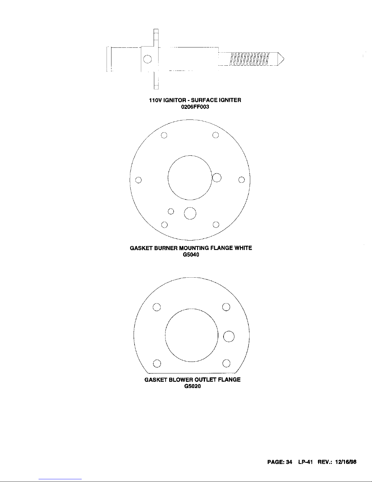
110V IGNITOR - SURFACE IGNITER
0206FF003
F_
©
GASKET BURNER MOUNTING FLANGE WHITE
G5040
GASKET BLOWER OUTLET FLANGE
G5020
PAGE: 34 LP-41 REV.: 12J16/98

GASORIFICECONVERSIONINSTRUCTIONS
1.
2.
3,
IF UNIT IS INSTALLED, TURN OFF POWER AND GAS SUPPLY BEFORE PERFORMING ANY CONVERSIONS.
TO CHANGE GAS ORIFICE, DISCONNECT UNION (#6) BETWEEN THE GAS VALVE AND AIR INLET; REMOVE OLD
GAS ORIFICE (#5), AND INSTALL THE NEW GAS ORIFICE IN THE UNION THAT CORRESPONDS TO THE UNIT MODEL
NUMBER AND FUEL BEING USED. SEE KIT CONTENT LIST FOR THE CORRECT ORIFICE TO BE USED. DISCARD
ORIFICES NOT USED.
FOR LABELING, CHANGE THE RATING PLATE LABEL FROM THE ORIGINAL FUEL TYPE TO THE NEW FUEL TYPE BY
PLACING THE NEW LABEL OVER THE EXISTING LABEL.
IMAX. INLET PRESSURE: 14" WC
IMIN NLET PRESSURE 7" WC
IRECOVERY RATING: 270 GPH
ii00 DEGREE RISE
ITANK CAPACITY 170 LITERS (45 US GAL,)
_TEST PRESSURE 2068 KPA
iWORKIN PRESSURE 1034 KPA
LLS1200 H 001
VOYAOE
SUP[R STaR
By Heo[ lro_srer producls Inc File: MHI8082 JS 2_5K
PO Box 429 _20 Braley Reao Classified by Jnoerwri;e_s Laboratories
Eos[ Freetown MA 02717 in _¢cordonce w;th American No_ionol
50B 763 8071 Standards hs_tute ANS_ Z2_ 103b 92
D;rect Ve,_ Au[omctic S[orage Wore r Heater Water Helle: and CAN 1 4 J M85
FOR YOUR SAFETY!
Do not store or use gasoline or other
flcmmob_e vapors or liquids in the
v[cin]ty of !hls or any other appliance]
IMAX INLET PRESSURE: 14" WC
IM_N INLET PRESSURE: 7" WC
I RECOVERY RATING: 270 G P H
I tOO DEGREE RISE
II[ANK CAPACRY 170 LITERS (45 US GAL)
iTEST PRESSURE 2068 KPA
IWORKLN PRESSURE 1034 KPA
ILS11OO-F OO1
I.........
Storage volume: 45 US Gallons, Moxlmum working pfessgre 150 PS,I, Test
Pressure 3DO PSI, Eleclrlcol 60 Hz 120 Volt, less than 12 amperes
¢
I heater s Under no c;rcumstonces shol_ Hear Transfer produc(s Inc, be herd
L liable for any such waler damage whatsoever
III1_
[_-j-_)UNION TOP
GAS ORIFICE
AFR INLET ADARTLR NUT_ AIR ORIFICE
WITH GLAND INSIDE
PAGE: 35 LP-41 REV.: 12/16/98

4. REPLACE GAS TYPE LABEL OVER GAS INLET PIPE.
©
_PLIANCF IS •
SE: UP FOR !
5. IF YOU ENCOUNTER COMBUSTION PROBLEMS, REFER TO PROCEDURE "1" ON PAGE 40.
GASVALVEREPLACEMENT-REMOVAL
1,
2.
3.
4.
5.
SHUT OFF POWER TO THE VOYAGER.
REMOVE THE DOOR FROM THE VOYAGER CABINET.
SHUT OFF THE GAS VALVE BY TURNING THE BLUE KNOB ON THE VALVE TO THE "OFF" POSITION.
SHUT OF THE GAS SUPPLY TO THE VOYAGER.
BREAK THE UNION ON THE GAS LINE LOCATED BEFORE THE GAS VALVE, AND REMOVE THE HALF OF THE
UNION THAT IS CONNECTED TO THE GAS VALVE INLET PIPE.
REMOVE THIS SIDE
OF UNLON.
6. REMOVE THE CLEAR VINYL HOSE THAT CONNECTS BETWEEN THE GAS VALVE AND THE TRAP ADAPTER.
DISCONNECT HOSE
FROM HERE
t
PAGE: 36 LP-41 REV.: 12/16/98

7. BREAK THE UNION THAT CONNECTS THE GAS VALVE TO THE AIR INLET MANIFOLD.
BREAK TH
8.
SLIDE THE GAS VALVE OUT THROUGH THE FRONT OF THE VOYAGER CABINET. REMOVE THE GAS VALVE
WIRING HARNESS FROM THE GAS VALVE.
GAS VALVE REPLACEMENT - INSTALLATION
NOTE:
IF YOU HAVE TWO MANOMETERS AVAILABLE, THEN FOLLOW INSTALLATION PROCEDURE #2. IF NO MANOMETERS ARE
AVAILABLE, USE INSTALLATION PROCEDURE #1.
PROCEDURE #1
1.
2.
3.
RE-CONNECT THE GAS VALVE WIRING HARNESS TO THE GAS VALVE.
SLIDE THE GAS VALVE BACK INTO POSITION BY PUTTING THE GAS VALVE INLET THROUGH THE GAS VALVE
INLET HOLE IN THE LEFT-TOP OF THE VOYAGER CABINET.
PLACE THE GAS ORIFICE BACK ON THE BOTFOM HALF OF THE UNION, AND TIGHTEN THE UNION.
4. RE-CONNECT THE CLEAR VINYL HOSE TO THE GAB VALVE AND TO THE TRAP ADAPTER.
CONNECT H
PAGE: 37 LP-41 REV.: 12/16/98

5,
6.
7.
RE-CONNECT THE SUPPLY GAS PIPING TO THE VALVE.
TURN ON THE GAS TO THE VOYAGER.
TURN THE BLUE KNOB ON THE GAS VALVE TO THE "ON" POSITION.
PILOT ADJ
8, REMOVE THE SMALL ROUND BRASS PLUG FROM THE GAS VALVE BY TURNING IT COUNTER-CLOCKWISE WITH A
PAIR OF SNAP RING OR NEEDLE NOSE PLIERS.
@
PILOT ADJ
9. TURN THE LINE VOLTAGE BACK ON, TO THE VOYAGER.
GAS VALVE ADJUSTMENT
I. LET THE UNIT START TO CYCLE AND LISTED CAREFULLY TO THE IGNITION. IF THE IGNITION WAS QUIET, THE
VALVE WILL NEED NO ADJUSTMENT. IF IT WAS A LOUD IGNITION OR THERE WAS NOT IGNITION AT ALL, FOLLOW
THESE STEPS:
A. IF THERE WAS NO IGNITION:
1. MAKE SURE THE GAS VALVE IS IN THE "ON" POSITION; GAS IS ON TO THE UNIT; AND THE GAS
VALVE WIRING HARNESS IS PLUGGED INTO THE GAS VALVE AND INTO THE CONTROL BOARD
2. TURN THE ADJUSTMENT SCREW UNDER THE BRASS CAP YOU REMOVED IN STEP #8 ABOVE.
TURN ONE FULL TURN CLOCKWISE WITH A SMALL FLATHEAD SCREWDRIVER.
A. IFTHE UNIT STILL DOES NOT LIGHT OFF, TURN THE ADJUSTMENT
SCRBN TWO PULL TURNS COUNTERCLOCKWISE
PAGE: 38 LP-41 REV.: 12/16/98

g. IF IGNITION WAS POOR:
1,
LOOK AT THE COLOR OF THE FLAME WHILE THE UNIT IS RUNNING, THROUGH THE SIGHT GLASS.
IF IT IS GREEN OR RED IN COLOR, OR THE HEATER WHISTLES ON IGNITION, TURN THE
ADJUSTMENT SCREW COUNTERCLOCKWISE AT V2TURN INTERVALS, UNTIL THE FLAME TURNS
BLUE/LIGHT BLUE IN COLOR, OR THE WHISTLING AT IGNITION STOPS. IF THE FLAME IS VERY
WEAK OR PULSING, TURN THE ADJUSTMENT SCREW CLOCKWISE UNTIL THE FLAME STEADIES.
GA% VA[ VE
ADJUSTMENT
SCREW
2. PUT THE GAS VALVE ADJUSTMENT SCREW COVER BACK IN PLACE AND TIGHTEN.
3. PUT THE VOYAGER CABINET DOOR BACK INTO PLACE.
PROCEDURE #2
1.
REMOVE THE OUTLET PRESSURE TAP PLUG FROM THE RIGHT SIDE OF THE GAS VALVE WITH A 3/16" ALLEN
WRENCH.
2.
3.
4.
5.
PUT A 1/8" NPT HOSE BARB IN PLACE OF THE OUTLET PRESSURE TAP PLUG. NO SEALANT IS REQUIRED ON THIS
FITTING.
RE-CONNECT THE GAS VALVE WIRING TO THE GAS VALVE.
SLIDE THE GAS VALVE BACK INTO POSITION BY PUTTING THE GAS VALVE INLET PIPE THROUGH THE GAS VALVE
INLET HOLE IN THE LEFT-TOP OF THE VOYAGER CABINET.
PLACE THE GAS ORIFICE BACK ON THE BOTTOM HALF OF THE UNION AND TIGHTEN THE UNION.
o ,_ _
!.;o.
11 " o ,
ORIFICE
PAGE:39 LP-41 REV.: 12/16/98

6,
CONNECT THE VACUUM HOSING ACCORDING TO THE FOLLOWING DIAGRAM:
• / , (.\vsJ.
,1
rc MANOMI TFR ,#2
7.
8.
9.
10.
RE-CONNECT THE SUPPLY GAS PIPING TO THE VALVE.
TURN ON THE GAS TO THE VOYAGER.
TURN THE BLUE KNOW ON THE GAS VALVE TO "ON".
P[LDT ADJ
REMOVE THE SMALL ROUND BRASS PLUG FROM THE GAS VALVE BY TURNING IT COUNTERCLOCKWISE WITH A
SMALL PUNCH AND HAMMER.
44
/ @
PLOT A]]J
11, TURN THE LINE VOLTAGE BACK ONTO THE VOYAGER.
PAGE: 40 LP41 BEV.: 11!/16/98

12. LET THE VOYAGER CYCLE. AFTER THE VOYAGER STARTS, LET IT RUN FOR 30 SECONDS, THEN ADJUST THE
GAS VALVE BY USING THE GAS VALVE ADJUSTMENT SCREW, SO THAT MANOMETER #2 READS EXACTLY THE
SAME AS MANOMETER #1.
EXAMPLE: IF MANOMETER #1 READS -.35" AND MANOMETER #2 READS .1"; YOU WOULD ADJUST THE GAS
VALVE BY USING THE GAS VALVE ADJUSTMENT SCREW, SO THAT THE MANOMETER #2 ALSO
READS -.35".
13.
14.
15.
16.
17.
18.
GAS VALVE
ADJUSTMEN]
SCREW
IF THERE WAS NO IGNITION:
A. MAKE SURE THE GAS VALVE IN THE "ON" POSITION, GAS IS ON TO THE UNIT, AND THE GAS VALVE
WIRING HARNESS IS PLUGGED INTO THE GAS VALVE AND INTO THE CONTROL BOARD.
B. TURN THE ADJUSTMENT SCREW UNDER THE BRASS CAP YOU REMOVED tN STEP #8. TURN ONE FULL
TURN CLOCKWISE WITH SMALL FLATHEAD SCREWDRIVER. IF THE UNIT STILL DOES NOT LIGHT OFF,
TURN THE ADJUSTMENT SCREW TWO FULL TURNS COUNTERCLOCKWISE.
SHUT THE VOYAGER DOWN, THEN START IT UP AGAIN; LET IT RE-LIGHT. IF THE IGNITION WAS GOOD, THE
VALVE NEEDS NO FURTHER ADJUSTMENT. IF THE IGNITION WAS POOR, SHUT DOWN THE UNIT AND LET IT
CYCLE AGAIN. TURN THE GAS VALVE ADJUSTMENT SCREW SO THAT MANOMETER #2 READS .10" MORE THAT
MANOMETER # 1. EXAMPLE: MANOMETER #1 READS -.35"; ADJUST MANOMETER #2 SO THAT IT READS -.25". IF
THIS DOES NOT STOP THE POOR IGNITION, ADJUST THE GAS VALVE ADJUSTMENT SCREW ANOTHER .10".
EXAMPLE: IF MANOMETER #1 READS -.35", MANOMETER #2 SHOULD BE ADJUSTED TO NOW READ -.15".
PUT THE GAS VALVE ADJUSTMENT SCREW COVER BACK IN PLACE AND TIGHTEN.
REMOVE ALL THE CLEAR VINYL HOSES FROM THE GAS VALVE.
REMOVE THE BARB IN THE OUTLET PRESSURE TAP, REPLACE IT WITH THE ORIGINAL PLUG, AND TIGHTEN.
RE-CONNECT THE CLEAR VINYL HOSE TO THE GAS VALVE, AND TO THE TRAP ADAPTER.
IIIII II1
_]_'___ CONNECT HOSE
HERE.
/
20. PUTTHE VOYAGER CABINET DOOR BACKIN PLACE.
PAGE: 41 LP-41 REV.: 12/16/98

IMPORTANTINSTRUCTIONSFORSSVHMODELS
HOWTHESYSTEMWORKSWITHRADIANTHEAT
BOTH THE VOYAGER SSV AND SSVH MODELS ARE VERY EFFICIENT AND POWERFUL WATER HEATING DEVICES. THE
VOYAGER SSV AND SSVH MODELS PRODUCE LARGER AMOUNTS OF HOT WATER IN A VERY SMALL COMPACT DESIGN,
WHEN COMPARED WITH CONVENTIONAL WATER HEATERS. HEAT TRANSFER PRODUCTS HAS DESIGNED THE VOYAGER
SSVH MODEL EXCLUSIVELY AS A COMBINED HOT WATER/RADIANT SPACE WATER HEATER. THE UNITS ARE BUILT WITH
A SECONDARY HEAT EXCHANGER TO TRANSFER HEAT FROM THE STORED WATER INTO THE CIRCULATOR LOOP FOR
THE FLOOR, CEILING, OR BASEBOARD RADIANT SYSTEM. THIS SECONDARY HEAT EXCHANGER ALLOWS THE VOYAGER
SSVH MODEL TO HEAT BOTH THE DOMESTIC WATER AND PROVIDE OUTPUT BY THE INSTALLATION OF A RE-CIRCULA-
TION LINE CONNECTED FROM DOMESTIC HOT WATER OUTLET TO DOMESTIC COLD WATER INLET. THE VOYAGER
SSVH-130 MODEL CAN TRANSFER UP TO 110,000 BTU's IN THE SECONDARY HEAT EXCHANGER AND ALSO DELIVER 180
GALLONS OF HOT WATER INTHE FIRST HOUR OF OPERATION. EVEN VOYAGER SSV MODELS MAKE GREAT RADIANT
HEATERS, WHEN DOMESTIC HOT WATER IS NOT NEEDED IN THE INSTALLATION. ANOTHER IMPORTANT FEATURE IS
THAT BOTH SSV AND SSVH MODELS HAVE THE ABILITY TO DIRECT VENT WiTH A ZERO CLEARANCE TOLERANCE TO ANY
COMBUSTIBLE SURFACE, WHICH ENABLES THE VOYAGER TO BE INSTALLED VIRTUALLY ANYWHERE! THIS TYPE OF
POWER, EFFICIENCY, AND INSTALLATION FLEXIBILITY IN SSV AND SSVH MODEL APPLIANCES IS A VOYAGER EXCLUSIVE
THAT NO OTHER WATER HEATER MANUFACTURER CAN OFFER!
HOW THE SYSTEM WORKS WITH HEATING/COOLING
BOTH SSV AND SSVH MODELS CAN WORK IN CONNECTION WITH AIR HANDLING EQUIPMENT TO PROVIDE AIR OR RADI-
ANT HEATING, COOLING, AND DOMESTIC HOT WATER. THESE TYPES OF SYSTEMS PROVIDE THE ADVANTAGE OF
ZONED HEATING AND COOLING; WHICH PROVIDE MUCH GREATER COMFORT AND OPERATING EFFICIENCY VERSUS
CONVENTIONAL SYSTEMS.
NOW TO INSTALL THE SYSTEM
IN THIS MANUAL YOU WILL FIND SAMPLE DRAWINGS WHICH CAN PROVIDE YOU WITH IDEAS ON HOW TO LAY OUT THE
SYSTEM. THE USE OF A MIXING VALVE IS ALWAYS RECOMMENDED TO ACHIEVE FLEXIBILITY IN ADJUSTING TEMPERA-
TURE TO MEET THE SYSTEM DEMAND. IT IS ESSENTIAL TO READ THIS INSTALLATION MANUAL TO ASSURE PROPER
OPERATION OF THE VOYAGER SYSTEM. AREAS IN THIS MANUAL THAT NEED SPECIAL ATTENTION ARE =CONDENSATE
REMOVAL"; "VENTING OF COMBUSTION GASES"; AND "CONNECTION OF A BRONZE CIRCULATOR BETWEEN DOMESTIC
HOT WATER OUTLET, DOMESTIC COLD WATER INLET".
NOTE:
IT IS VERY IMPORTANT TO FOLLOW EITHER LOCAL OR FEDERAL PLUMBING CODES WHEN INSTALLING AND OPERATING
A MIXING VALVE FOR A DOMESTIC HOT WATER SYSTEMI
HOW TO SIZE THE COMBINATION SYSTEM FOR RADIANT HEATING
IT IS IMPORTANT TO SIZE BOTH HEATING LOAD AND DOMESTIC HOT WATER LOAD, IN CHOOSING WHICH VOYAGER SSVH
MODEL YOU WILL NEED TO PURCHASE FOR THE JOB. ON THE FOLLOWING PAGE IS A CHART WHICH REPRESENTS
DESIGN OUTPUTS OF THE SECONDARY HEAT EXCHANGER IN THE VOYAGER SSVH MODEL. THIS CHART OUTLINES OUT-
PUT CHARACTERISTICS IN TERMS OF FLOW RATE THROUGH THE SECONDARY HEAT EXCHANGER, TEMPERATURE RISE,
AND BTU OUTPUT. IT IS IMPORTANT TO CHECK WITH YOUR RADIANT SUPPLIER ON THE OUTPUT TEMPERATURE,
DESIGN TEMPERATURE RISE OR DELTA TEE, AND THE TOTAL BTU OUTPUT REQUIRED FOR THE JOB. A BRONZE CIRCU-
LATOR BETWEEN DOMESTIC HOT WATER OUTLET AND DOMESTIC COLD WATER INLET IS REQUIRED. ONCE YOU HAVE
DETERMINED YOUR SYSTEM OUTPUT REQUIREMENTS, REFER TO "VOYAGER SSVH MODEL SIZING CHART" ON NEXT
PAGE TO DETERMINE MODEL AND FLOW RATE REQUIRED THROUGH THE SECONDARY HEAT EXCHANGER; IN ORDER TO
MEET THE LOADS OF THE SYSTEM. EXAMPLES ARE PROVIDED TO GUIDE THROUGH THE SELECTION PROCESS. ONCE
WE KNOW THAT THE SECONDARY HEAT EXCHANGER HAS BEEN SIZED CORRECTLY TO MEET THE RADIANT HEAT LOAD,
WE MUST NOW LOOK INTO THE HOT WATER LOAD. FIRST YOU NEED TO UNDERSTAND THE DIFFERENCE BETWEEN
FIRST DRAW CAPACITY AND FIRST HOUR CAPACITY. FIRST DRAW CAPACITY IS ESTABLISHED AS THE TIME FRAME AT
DIFFERENT OUTPUT RATES WHICH THE VOYAGER SSVH MODEL CAN DELIVER THE DESIRED TEMPERATURE BEFORE
THE TANK RATE INPUT AND STORAGE ARE CONSUMED. THIS USUALLY OCCURS WHEN THERE IS A LARGER DRAW OF
HOT WATER IN A VERY SHORT TIME FRAME. (EXAMPLE= HOT TUB 80 GALLON WITH A FILL RATE OF 10 MINUTES) FIRST
HOUR RATING IS ESTABLISHED AS A RATING SYSTEM TO COMPARE THE WATER HEATER'S ABILITY TO RECOVER OVER A
ONE HOUR PERIOD. THE FIRST HOUR RATING CAN BE VERY MISLEADING WHEN THE HOT WATER LOAD IS REQUIRED IN
A VERY SHORT PERIOD OF TIME. NOW WE CAN DETERMINE WHICH VOYAGER SSVH MODEL WILL SUIT YOUR NEEDS
FOR THE JOB. TO DO THIS, REFER TO THE DOMESTIC HOT WATER CHART. IF THE DOMESTIC HOT WATER DEMANDS
EXCEED THE VOYAGER SSVH'S CAPACITY, THEN A STORAGE RE-CIRCULATION TANK CAN BE INSTALLED TO MEET THE
SYSTEM HOT WATER LOAD. AFTER YOU HAVE SIZED YOUR DOMESTIC LOAD AND HEATING LOAD, YOU ARE NOW READY
TO CHOOSE THE VOYAGER SSVH MODEL SUITABLE FOR THE JOB!
PAGE: 42 LP-41 REV.: 12/16/98
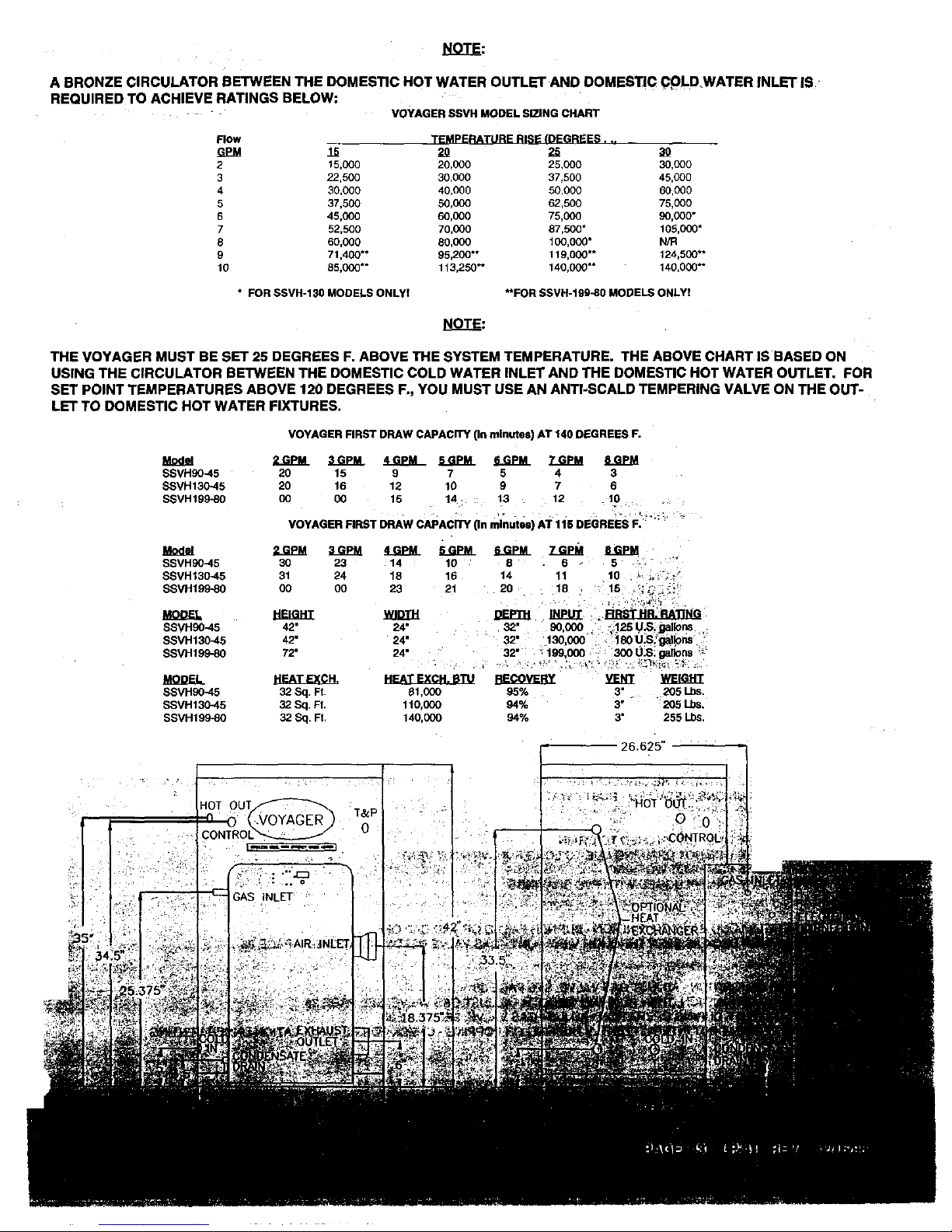
NOTE:
A BRONZE CIRCULATOR BETWEEN THE DOMESTIC HOT WATER OUTLET AND DOMESTIC C_LD,WATER INLET IS
REQUIRED TO ACHIEVE RATINGS BELOW:
VOYAGER SSVH MODEL SIZINGCHART
Flow TEMPERATURE RISE (DEGREES...
G_M lS 20 2S
2 15,co0 20,000 25,ooo 30,000
3 22,500 30,000 37,500 45,000
4 30,000 40,000 50,000 60,000
5 37,500 50,000 62,500 75,000
6 45,000 60,000 75,000 90,000"
7 52,500 70,000 87,500" 105,CO0"
8 60,000 80,CO0 1CO,000" N/R
9 71,400"* 95,2CO** 119,000"* 124,500**
10 85,C00"* 113,250" 140,0C0"* 140,000"*
* FOR SSVR-130 MODELS ONLYI **FOR SSVH-199-80 MODELS ONLYI
THE VOYAGER MUST BE SET 25 DEGREES F. ABOVE THE SYSTEM TEMPERATURE. THE ABOVE CHART IS BASED ON
USING THE CIRCULATOR BETWEEN THE DOMESTIC COLD WATER INLET AND THE DOMESTIC HOT WATER OUTLET. FOR
SET POINT TEMPERATURES ABOVE 120 DEGREES F., YOU MUST USE AN ANTI-SCALD TEMPERING VALVE ON THE OUT-
LET TO DOMESTIC HOT WATER FIXTURES.
VOYAGER FIRST DRAW CAPACITY (In minutes) AT 140 DEGREES F.
J_ _ _ 4GPM 5GPM 6GPM 7GPM 8GPM
SSVH90-45 20 15 9 7 5 4 3
SSVH130-45 20 16 12 I0 9 7 6
SSVH199-80 CO 00 15 14 13 12 10
SSVH90-45
SSVH13O-45
SSVH199-80
SSVHg0_5
SSVH13045
SSVH199-80
SSVHg0_5
SSVH130-,45
SSVH199_0
VOYAGER FIRST DRAW CAPACITY (In minutes) AT 115 DEGREES F.
2GPM 3GPM 4GPM SGPM SGPM
30 23 14 10
31 24 18 16
00 O0 23 21
HEIGHT
42" 24"
42" 24"
72" 24"
HEAT EXCH. BTU
32 Sq. Ft. 81,000
32 Sq. R. 110,000
32 SO. R 140,000
Z-GEM
8 6 5
14 11 10 _, _, J
20 18 15 .'; ;_"_:.;'_
DEPll-I INPUT RRST HR. RAllNG
32. 9o.oo0 ¥12sU-S.gal_
32. 13o,ooo lsou.s;'_o_ "
32" _199.000 - '300U.S. gagons ;_'
REVERY _ ]_FJ_dI
95% 3" . 205 Lbs,
94% 3" 205 Lbs,
94% 3" 255 Lbs
26.62_'

THIS VOYAGER HAS THE NEW 1200 BOARD AND BLOWER SYSTEMI THE ADDmONAL FEATURES ARE LISTED BELOW:
THE BOARD WILL DETECT PROPER POLARITY BY ILLUMINATING THE GREEN LED LIGHT LOCATED ON THE LOWER RIGHT
CORNER OF THE BOARD. NO LIGHT MEANS IMPROPER POLARITYI
2. THE BLOWER CABLE AND THE CURRENT LIMITER HAVE BEEN ELIMINATED.
3. THE LED DISPLAY IS FIVE TIMES BRIGHTER; GIVING GREATER VISIBILITY IN BRIGHT LIGHT.
4. THE PUSH BUTFON IN THE FRONT OF THE CABINET ALLOWS THE USER TO READ IGNITOR DRAW IN
AMPS (2.5 - 3.5), AND FLAME QUALITY IN MICRO AMPS (4.5 - 5.1). TO READ IGNITOR DRAW, WAIT FOR THE LED LIGHT FOR THE
IGNITOR TO COME ON, THEN SIMPLY PUSH THE BUTTON IN ON THE FRONT OF THE CABINET. TO READ FLAME QUALITY, WAIT
FOR THE GAS VALVE TO BE ACTIVATED AND THE IGNITOR LIGHT TO GO OFF, THEN SIMPLY PUSH IN THE BUTFON ONCE. THIS
WILL TAKE PLACE IN THE NORMAL OPERATING SEQUENCE IN A HEAT CYCLE.
5. THE 1200 BOARD AND BLOWER SYSTEM PARTS ARE NOT INTERCHANGEABLE WITH THE VOYAGER PARTS (1000 SYSTEM)
PREVIOUS TO THE 1200 SYSTEM. PARTS FOR THE OLD 1000 VOYAGER SYSTEM ARE STILL AVAILABLE THROUGH OUR
STANDARD DISTRIBUTION.
MOST COMMON VOYAGER INSTALLATION CONCERNS
VENTINg_:
VENT LENGTH TOO LONG - OVER 85'
VENTING NOT PITCHED PROPERLY - CONDENSATE BUILD UP IN VENT
EXHAUST GAS RE-CIRCULATION - VENT TERMINALS NOT USED, WRONG FITI-INGS USED, SIGHT PROBLEMS
BUSH IN FRONT OF VENT TERMINAL
INSIDE CORNER OF BUILDING FOR VENT LOCATION
OVERHANG WITH VENT UNDERNEATH
COMPOUND ROOF PITCH, OR ABOVE ROOF FIRE WALL
ADDITIONAL FITrlNGS INSTALLED INTO TERMINALS
VENT SIZED FROM 3" TO 4" BY USING BUSHINGS - INSTEAD OF REDUCING COUPLING OR REDUCING ELBOW
VENT CHANGED FROM 3" TO 4" - WITHOUT GOING REQUIRED 10' ON BOTH INTAKE AND EXHAUST
VENTING NOT CLEANED AND GLUED TOGETHER FOR PRESSURE TIGHT JOINTS
INTAKE AIR CONTAINING EXHAUST FROM ANOTHER VENT OR APPLIANCE
GAS PRESSURE TOO LOW - NEED 7" GAS PRESSURE UP TO 14" GAS PRESSURE
GAS METER TOO LOW IN CAPACITY
GAS REGULATOR NOT SIZED PROPERLY - TOO LOW IN CAPACITY
GAS PIPE TOO SMALL - _" MINIMUM GAS SUPPLY SIZE
GAS REGULATOR TOO CLOSE TO APPLIANCE - NEED 10' OF PIPE FOR EVERY 2C0_000 BTU'S PER HOUR
GAS REGULATOR WITH LONG VENT OR BLEED VENT ORIFICE - REGULATOR SLOW TO RESPOND
GAS METER RESTRICTION, OR IN NEED OF REPAIR/REPLACEMENT
GAS SUPPLy PRESSURE DROPS BELOW 3Y2"WHEN APPLIANCE FIRES
APPLIANCE NOT GROUNDED
ELECTRICAL POLARITY REVERSED - FLAME WILL LIGHT BUT GO BACK OUT IN 4-6 SECONDS VOLTAGE TOO LOW OR TOO HIGH
APPLIANCE CYCLES, BUT NO IGNITION - LOOK FOR GLOW FROM IGNITOR, IF NOT, REPLACE IGNITOR
.' SSVH MODELS WITHOUT RE CIRCULATING PUMPINSTALLED& WITHOUT WIRING IN PARALLELWITH HEATING CIRCULATOR
DIELECTRIC UNIONSINSTALLED- RUSTY WATER
NOT DRAININGDUE TO LONG RUN WITHOUT VENT
4- BURNER FAILED OR END CAP OFf
VALVE I_IEEDS ADJUSTMENT, PAGE 38
 Loading...