

PROGRAM LOCK
THERMAL LOCKOUT
DIFFERENTIAL
E
PRESS TO DISPLAY
MADE IN U.S.A.
CONNECTED
MUST
CLOCKNEUTRAL
LINE
1 32
OPTION
READ INSTRUCTIONS BEFORE PROGRAMMING
PROGRAM
BE
R
B
OUTPUT
W
1 2
3 4
5 6
AUX. OPTION
789
10 1211 13
OUTPUT
RELAY
UNLOCK
BY-PASS
AUTO
CLOCK
AUX.1OPTION
SUMMER
WINTER
RUN
N
C
R
ADJUSTMENT
BOOST
VARI
OPTIONOPTION
1714 15 16
MANUAL
X
WITH
VARI
SHUT DOWN
Z
ON
I
3
OPTION
2
ADVANCE
REVIEW
PAIR SHOWN
ERASE
Y
HEATING
SYSTEM
SENSOR
A
S
E
OFF
FAST
CYCLE FOR
TESTING
MORNING BOOST
120
SHUT DOWN CURVE
Series
(DAY)
SYSTEM IN
NORMAL
AM
TUE
N
HEAT ADJUSTMENT
SYSTEM IN
SAVE
(NIGHT)
OUTDOOR SENSOR SET POINTS
SHIFT
HOURS
MON
CURRENT STATUS INDICATORS
E
A
L
C
B
P
O
NORMAL
H
G
F
E
S
S
D
J
K
M
L
-DAY
I
THU
CLOCK PROGRAM CONTROLS
MINUTESPMDAY
WED SATFRI
SUN
TEMP
2
COPYDAY
OFF
MANUAL MINUTES
VARI-BOOST /
1
20
OUTSIDE
40
3
60
4
80
BOOST
K
-NIGHT
R
E
A
L
E
C
B
SAVE
F
S
S
O
M
D
E
G J
H
I
R
P
E
N
O
M
O
L
M
Gold
SERIAL NO.
5
6
100
USE COPPER WIRE ONLY
OUTPUTS:
120VAC, 6A RESISTIVE
1A PILOT DUTY
15A TOTAL FOR ALL CIRCUITS
HEAT-TIMER PANEL
HWR, HWRQ, MPC, MPCQ, SRC, Multi-MOD
HEAT SOURCE
ACTIVATED
HEAT CIRCULATION
ESTABLISHED
SYSTEM
IN CYCLE
J1
X1X2 X3
120
VAC
Power
Sensor Link
Receiver
Sensor Link
Transmitter
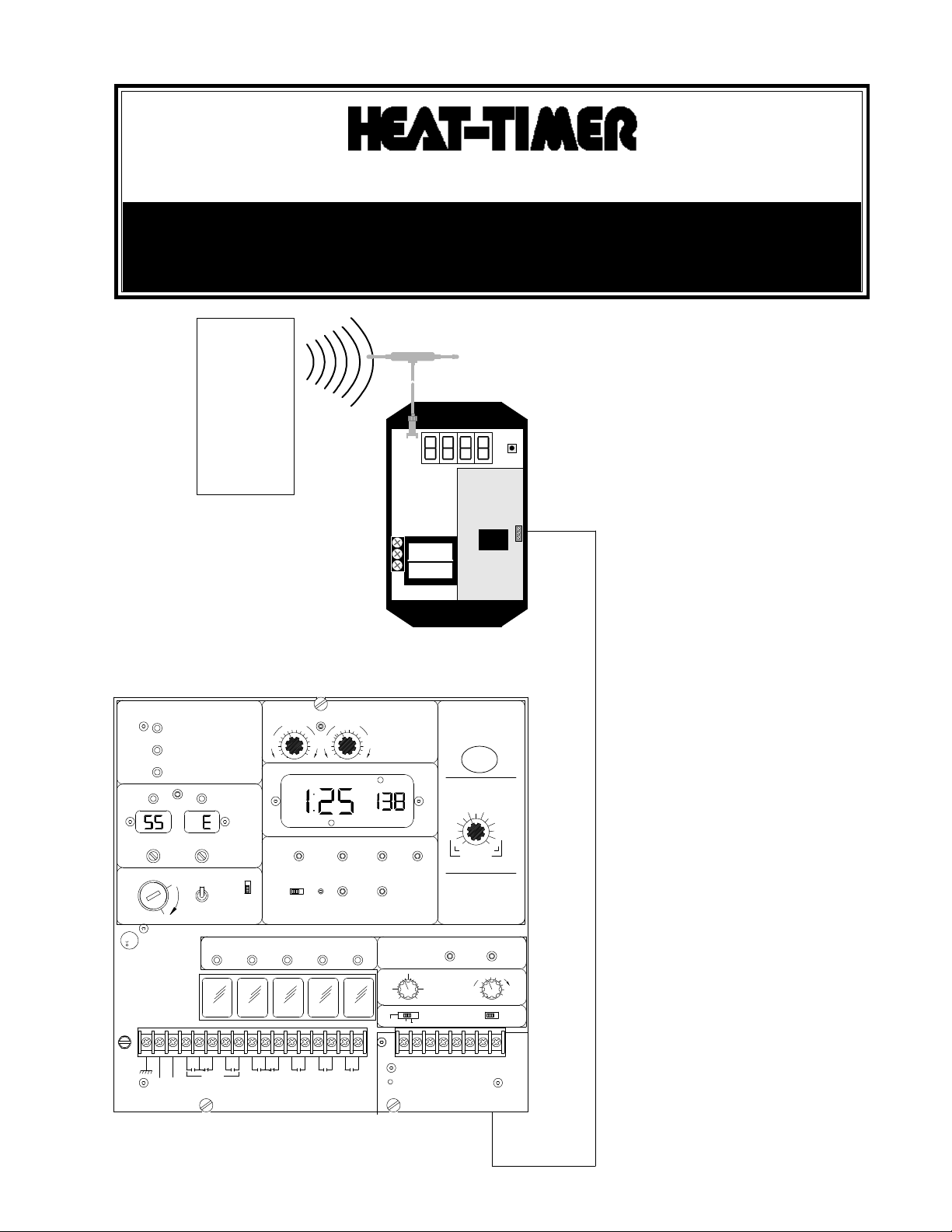
INSTALLATION/OPERATING INSTRUCTIONS
SENSOR LINK
The Sensor Link system consists of a
Receiver and one or more Temperature
or Pressure Transmitters. The Receiver
is designed to intercept and decode
the wireless information being emitted
by the Transmitters and forward the
data to the Heat-Timer panel (HWR,
HWR-Q, MPC, MPC-Q, SRC, or MultiMOD) via a wired connection.
Instruction to User
This equipment has been tested and found to
comply with the limits for a class B digital
device, pursuant to part 15 of the FCC Rules.
These limits are designed to provide
reasonable protection against harmful
interference in a residential installation. This
equipment generates, uses and can radiate
radio frequency energy and if not installed
and used in accordance with the instructions,
may cause harmful interference to radio
communications. However, there is no
guarantee that interference will not occur in
a particular installation. If this equipment
does cause harmful interference to radio or
television reception, which can be determined by turning the equipment off and on,
the user is encouraged to try to correct the
interference by one or more of the following
measures:
* Reorient or relocate the receiving
antenna.
* Increase separation between the
equipment and receiver.
* Connect the equipment into an outlet on
a circuit different from that to which the
receiver is connected.
* Consult the dealer or an experienced
radio/TV technician for help.
This equipment has been certified to comply
with the limits for a class B computing
device, pursuant to FCC Rules. In order to
maintain compliance with FCC regulation,
shielded cables must be used with this
equipment. Operation with non-approved
equipment or unshielded cables is likely to
result in interference to radio and TV
reception. The user is cautioned that changes
or modifications made to the equipment
without the approval of the manufacturer
could void the users authority to operate this
equipment.
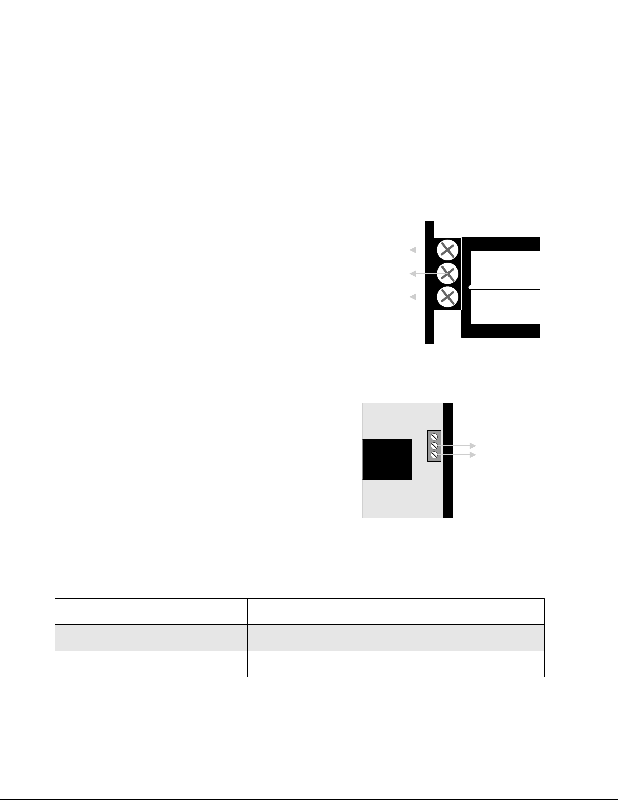
SENSOR LINK RECEIVER INSTALLATION
GND
Neutral
Line
Wire Type
Belden 8471
Belden 85102
Unshielded
Twisted Pair
16AWG
Gauge Maximum Length (ft) Maximum Temp (°F)
Unshielded
Twisted Pair
16AWG
1200
1200
140
185
J1
X1 X2 X3
To
Network
Terminals
A &B
Mount the enclosure
In a location central to the various Transmitters.
To prevent unauthorized tampering, the Receiver should be located
in an inconspicuous area, or in an area with limited access.
The Receiver must be located where the ambient temperature will not
exceed 130°F and away from any steam or moisture.
Attach the Receiver to a flat surface by screwing through the
mounting holes located on the top and bottom flange.
If desired, the Receiver may also be installed inside a metal enclo-
sure.
Power Wiring
Bring the 120VAC 60Hz power wires through the round opening in
the enclosure.
Class 1 voltages must enter the enclosure through a different
opening from any Class 2 voltage wiring.
Connect power to the terminals as shown at right.
The GND terminals MUST be connected to earth ground.
Network Wiring
Use 2-wire unshielded twisted pair (see specification below).
There is no polarity to observe. Either network wire from the
Receiver can be attached to Heat-Timer panel (HWR, HWRQ, MPC,
MPCQ, SRC, or Multi-MOD) Network terminals A or B.
Bring the network wiring through the rectangular opening in the
enclosure.
Network wiring must enter the enclosure through a different opening
from any Class 1 voltage wiring.
Wire the network connections to the terminal block marked J1,
terminals X1 and X2.
The wires can be run in virtually any configuration back to the Heat-
Timer panel. They can be wired sensor to sensor (daisy chained).
They can be wired in a star configuration, with each sensor pair
brought back to the panel. Finally, there can be any combination of
the two.
The Receiver has a specific ID number. The ID number is on the back
of the Receiver, and is on the Network Identification card which is
provided. Fill out the location of the Receiver on the Network
Identification card and return it to the Heat-Timer network adminis-
trator.

D3 D2 D1
D3 D2 D1
Push
Button
Mounting and Connecting the Antenna
Antenna
Wire
Adhesive
Pad
Only
Transmitters in
Test Mode
All
Transmitters
Description
Sn S.n Serial number of the Transmitter
tE t.E Temperature of the Transmitter
Display Code
coUn c.oUn
The total number of packets correctly received since startup
(used for diagnostic purposes)
rSSI r.SSI
2 Left hand digits - Data signal strength
2 Right hand digits - Noise strength
The Antenna should be mounted in a convenient location within six
feet of the Receiver.
Do not cut or splice the antenna wire provided.
Make sure the surface where the Antenna will be mounted is flat,
clean, dry, and will not be subject to moisture or temperatures which
exceed 130°F.
Remove the backing to expose the adhesive pad on the back of the
antenna and press it to the mounting surface.
To connect the Antenna to the Receiver, screw the nut on the end of
the Antenna wire to the threaded metal connector extending from the
Receiver enclosure.
SENSOR LINK RECEIVER OPERATION
Power Up Display
When the receiver is first powered, 8 will be displayed in each of the
digits in turn, moving from right to left.
Next the display will briefly show the version number, and then go
blank.
During this period, the green LED (D1), yellow LED (D2), and red
LED (D3) will flash or light.
When the display goes blank, only the red LED (D3) will remain on
to indicate the Receiver is powered.
Display Modes
Pressing the push button will set the display mode for the Receiver.
Once a display mode is selected, the Receiver will remain in the
selected display mode until the push button is pressed and a new
mode is selected.
If the display code with a dot is selected, then the selected display
information will be shown whenever the Receiver gets data from any
Transmitter on its channel. Each Transmitter normally emits data
every 4 to 5 minutes.
When setting up Transmitters, they can be put in a Test mode so
they emit data much more frequently. To only display information
from a Transmitter in Test, select the display code without a dot.
The chart below describes the various display modes:

SENSOR LINK TRANSMITTER
Test
Mode
Button
Batteries
Installation
Find an approximate location for the Transmitter, located away from
direct sunlight or other heat sources. Do not locate a Transmitter in
either a kitchen or a bathroom.
The range of temperatures at the Transmitter location should be
between 32 and 150°F. If the temperature experienced by the Transmitter is outside of this range, battery life will be shortened.
Open the Transmitter by inserting your two thumbs in the large
rectangular opening at the back of the enclosure and prying it open.
Make sure the Receiver is programmed to read Sn (see above).
Remove the plastic tab to connect the batteries and activate the
Transmitter.
Push the button on the Transmitter to put it in the Test mode. It will
remain in the Test mode for five minutes. In the Test mode, the
Transmitter will emit data more often than during normal operation.
Go to the Receiver and watch the display until the serial number of
the new Transmitter being installed is displayed. Only the last 4
digits of the serial number will be shown.
If the Receiver does not register the new Transmitter, move it to
another location.
When a location with a good signal is found, mount the Transmitter
to a flat surface using the two oval mounting slots molded in the
base of the enclosure.
The Transmitter can be mounted either vertically or horizontally.
Replace the Transmitter cover.
Operation
The Transmitter should operate for years without any maintenance.
The batteries will need to be replaced every 3 to 8 years.
The Transmitter requires three AAA, 1.5 Volt batteries. Be sure to
observe that the positive side of the battery faces the center of the
Transmitter board as shown in the diagram at right and which is also
clearly marked on the board itself.
059265-00 REV A
 Loading...