


INSTALLATION/OPERATING INSTRUCTIONS
RSM
A Control for Under Slab Heating Systems
Used to Melt Ice or Snow
How the RSM works...
The RSM is designed to control under slab heating systems to prevent accumulations of ice or snow. To do this, it
monitors three temperatures, the outside temperature, the temperature of the fluid going to the slab, and the temperature
of the fluid returning from the slab.
The slab must be kept above freezing (32°F) whenever there could be frozen precipitation. Therefore, any ice or snow
which falls on the slab will melt immediately . If precipitation is allowed to accumulate before the slab is heated, an effect
called bridging can occur. The snow or ice directly in contact with the slab will melt. But the snow above will act as an
insulator, reflecting the heat back into the slab. The slab itself will be dry , but the remaining accumulation will melt very
slowly. To prevent this, the RSM activates the slab heating system whenever the outside temperature falls below the
adjustable outdoor cutoff temperature or whenever the optional external system starter is activated.
Once the slab heating system is activated, the amount of energy entering the slab is determined by the difference between
the temperature of the fluid going to the slab (the Slab Supply) and the temperature of the fluid returning from the slab
(the Slab Return). The difference between these two is called the ∆ (Delta)T or the difference in temperature. The ∆T will
be different for each slab composition. The higher the ∆T, the more energy is being input to the slab. If the ∆T is too
large, the slab itself can be damaged. The RSM provides a maximum ∆T adjustment which can be set from 5°F to 50°F
The RSM will control a 3-way motorized mixing valve to regulate the amount of heat being supplied to the slab. The
motorized valve will mix the heated fluid from the heat source with the fluid returning from the slab. As the slab or its
components can be damaged by excessive temperatures, the maximum temperature for the slab supply can be adjusted
from 70°F to 180°F. If the Slab Supply temperature reaches this limit, the control will immediately begin to close the valve.
Due to the twin constraints of maximum ∆T and maximum Slab Supply temperature, as well as the nature of under slab
heating systems, a typical slab will take many hours to reach melting temperatures. A 24 hour warm-up period is not
unusual. The RSM is provided with a Tune adjustment to insure the slab temperature will be sufficient to melt frozen
precipitation once the warm-up period has ended. The Tune value compensates for both different slab types and
different outdoor weather conditions. After making a change in the Tune value, it is necessary to wait at least several
hours before accessing what affect it will have on slab temperatures.
WARNING: This Heat-Timer control is strictly an operating control; it should never be used as
a primary limit or safety control. All equipment must have its own certified limit and safety
controls required by local code. The installer must verify proper operation and correct any
safety problems prior to the installation of this Heat-Timer control.
1
INSTALLATION
Mounting the control
• Select a location which is indoors, or which is protected from the elements. The control must be protected from
extreme heat or cold.
• The RSM is designed to mount on a standard 1900 (4" x 4") electrical box or can be flush mounted on a panel with the
extension skirt included.
• Before mounting, bring the power and load control circuit wiring into the 1900 box and connect to the individual wires
coming from the back of the control (See Wiring the Power and W iring the Output).
• Use the two screws provided to mount the RSM to the 1900 box.
Installing the sensors
• All three sensors are interchangeable.
• The sensor wires can be extended up to 500' by splicing with two conductor 18 gauge wire. Do not run wires in
conduit with line voltage.
• The Outdoor sensor should measure approximately the same outdoor air temperature as the slab will experience.
Therefore, mount the sensor away from any doors, windows, exhaust fans, vents, or other possible heat sources.
Keep the sensor out of direct sunlight. Locate the sensor on the north side of the building or in a similarly shady
location.
• The Slab Supply and Slab Return sensors must be installed in 3/8" ID immersions wells (HT #904011 or equivalent).
• The immersion well for the Slab Supply should be put in the fluid going out to the slab, approximately 10' past the heat
source.
• The immersion well for the Slab Return should be put in any convenient location where the fluid has returned from the
slab.
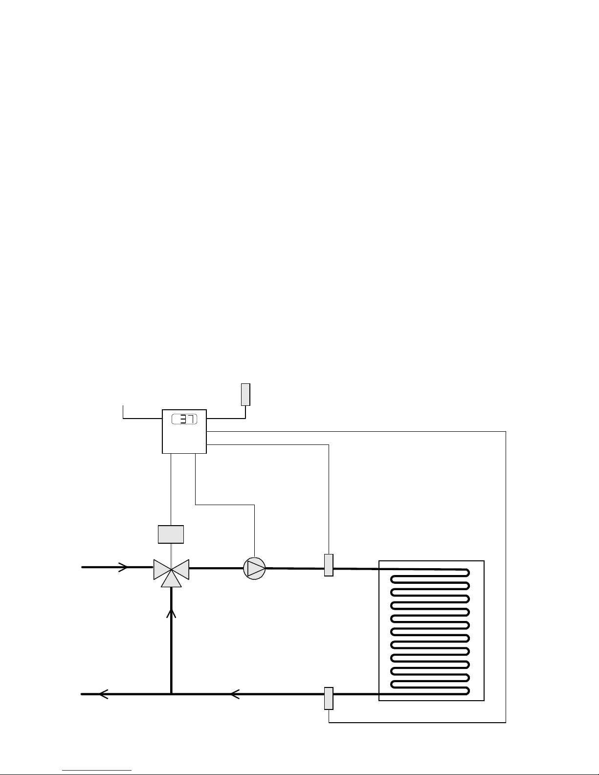
Optional
System Starter
Motorized
Valve
Heat
Source
TYPICAL INSTALLATION
Outdoor
Sensor
Slab
Pump
Slab
Supply
Sensor
Slab
Return
Sensor
2

Wiring the Power
• Attach line voltage to the two orange wires extending from the back of the RSM.
• Use wire nuts, or wrap the connections with electrical tape.
• Class 1 voltages must enter the 1900 box through a different opening from any Class 2 wiring.
Wiring the Sensors
• The sensor wires have no polarity . Either wire from a sensor can be connected to the appropriately marked RSM screw
terminal (see below) or the sensor common marked COM.
• Either or both screw terminals marked COM can be used as the sensor common. They are interchangeable.
• The two wires from the Outdoor sensor must be connected to the RSM front screws marked OUT and COM.
• The two wires from the Slab Supply sensor must be connected to the RSM front screws marked SUP and COM.
• The two wires from the Slab Return sensor must be connected to the RSM front screws marked RTN and COM.
Wiring the Output - Heat Source
• The RSM has one set of Normally Open (N.O.) dry contacts (blue wires) to activate the heat source for the slab.
• The N.O. contacts do not output power. They simply switch power through the circuit.
• If the heat source will be active whenever the RSM will activate the slab heat (as would be the case if the heat source is
also used for space heating), connect the blue wires in series with the power for the slab pump.
• If the boiler for the slab heating system has a dedicated pump, simply connect the blue wires in series with the limit
controls of the boiler so that both the boiler and pump start.
• If the boiler and pump for the slab must be energized separately , use the blue wires to ener gize an external double pole
single throw (DPST) relay. Attach one set of external relay contacts in series with the slab pump power. Attach the
other set of external relay contacts in series with the limit controls of the slab boiler.
• The RSM contacts can switch 10A, 1/8 HP at 120V. If the slab pump or boiler requires more power , an external relay
must be used.
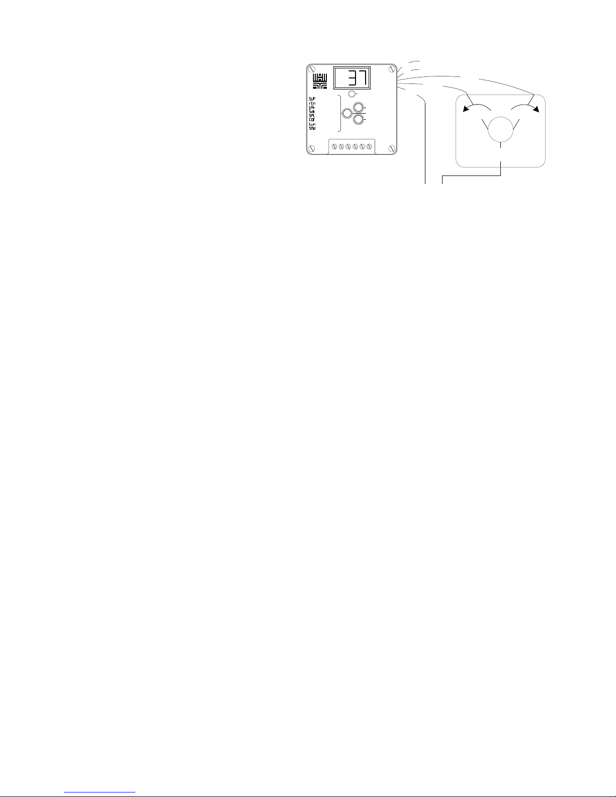
Outdoor Sensor
Slab Supply Fluid Sensor
Slab Return Fluid Sensor
= Supply Temp
= Return Temp
= Target
T
= Slab
∆
= Supply Limit
= Cut-Off Temp
= Tune
OUT SUP RTN COM EXT COM
WIRING DIAGRAM
OUTPUT
UP
PRESS TO READ
DOWN
To Optional
External Starter
Blue
Blue
Red
White
Black
Orange
Orange
N.O. Contacts
Activate Heat Soure
Valve Motor Common
Valve Motor Open
Valve Motor Close
120VAC Input
3
Wiring the Output - V alve Motor
• The valve outputs are dry contact only. They do not
source any power to the valve motor.
• The RED wire is COMMON.
• The WHITE wire connects to OPEN (for more heat).
• The BLACK wire connects to CLOSE (for less heat).
• The wiring to Heat-Timer Radiant Valves (3-way
HT#9285xx or 4-way HT#9284xx) is shown left. If using
other valves, check the appropriate wiring with the valve
= Supply Temp
= Return Temp
= Target
T
= Slab
∆
= Supply Limit
= Cut-Off Temp
= Tune
= Slab Adjust
OUT SUP RTN COM EXT COM
OUTPUT
UP
PRESS TO READ
DOWN
Blue
Blue
RED
BLACK
WHITE
BLACK
3
2
BROWN
M
Heat-Timer
1
Radiant
BLUE
Valve
manufacturer.
24VAC
Wiring the Optional External System Starter
• The EXT and COM terminals may be used as an optional external system starter. The external starter signal must be a
dry contact only . If power is applied across the EXT and COM terminals, the RSM may be damaged.
• A closure (short) across the terminals marked EXT and COM will cause the RSM to activate the slab heating system.
The RSM will keep the system activated until the external starter signal is removed.
• T o activate the slab heating system exclusively with the external starter , set the Outdoor Cutof f Temperature to OFF
(see pg. 5).
Setting the Operating Mode
• The RSM can be field adjusted to display values either in °F or °C.
• The sensors input range is from -35 to 250°F or from -30 to 120°C.
• Do the following to set the desired range:
1. Remove power to the RSM (if it was powered) and reapply power.
2. The display will show the version number of the RSM software.
3. W ait approximately 5 seconds and the display will change to read either °F or °C. If the display shows °F the RSM
will operate in Fahrenheit degrees. If the display shows °C then the RSM will operate in Celsius degrees.
4. If the desired range is shown, there is no need to proceed with the following steps.
5. Hold down the PRESS TO READ button while pushing the UP or DOWN button to toggle between displays of °F
or °C.
6. When the correct range is shown, release the button and wait approximately 5 seconds. If any changes were made
the display will flash. Then the RSM will display the outdoor air temperature.
Initial Settings
• After setting the operating mode, the RSM will display the outdoor air temperature. This is the default value for the
RSM display .
• T o see and/or adjust the other parameters, press then release the left button marked PRESS TO READ. The RSM will
display a code to indicate which parameter will be displayed next. After two seconds, the value of the parameter will
be shown.
• For those parameters where the values can be set (described pg. 5), press the UP or DOWN button to change the value
while it is being displayed. Holding down the UP or DOWN button will cause the value to change more quickly .
• The Slab ∆(delta) T must be set to the slab design parameter for the maximum temperature differential between the
slab supply and slab return temperatures (see pg. 6 for details).
• The Supply Limit must be set to the manufacturer's specification for the slab or the slab components. If high temperatures will damage the slab or the slab components, a separate limit controller should be installed (see pg. 6 for details).
• The Outdoor Cutoff comes factory set at 38°F. Therefore, the outdoor air temperature will need to fall below 38°F
before the heating system will be activated (see pg. 6 for details).
• The Tune comes factory set at 0. This value will need to be adjusted when the heating system is running and there is
precipitation (see pg. 6 for details).
4

DISPLAY SETTINGS and ADJUSTMENTS
PRESS
LEFT
BUTTON
Once
Twice
3 times
4 times
5 times
6 times
RSM
DISPLAY
Supply Temp
Return Temp
Target
Slab ∆T
Supply Limit
Outdoor Cutoff
Release center button to read value
If value needs adjustment, press the UP or DOWN buttons
To make large changes, keep the UP or DOWN button pressed
This is the temperature of the fluid being supplied to the slab. If it does
not read correctly, check the
This is the temperature of the fluid returning from the slab. If it does not
read correctly, check the
This is the target supply fluid temperature. The RSM controls the
motorized valve to hold this target temperature. The target will change
based on the sensor readings and the parameters set below.
The Slab ∆(Delta) T is determined by the design specifications for the
particular slab. The Slab
Slab Supply and Slab Return temperature. The Slab
from 5 to 50°F.
The Supply Limit is the highest temperature for which the slab heating
system is rated. The manufacturer will specify the maximum temperature for their components. The Supply Limit can be adjusted from 70
to 180°F.
The heating system will be activated when the outdoor temperature is
below the Outdoor Cutoff. The Outdoor Cutoff temperature can be set
to OFF, adjusted from 20°F to 50°F, or set to ON. In the OFF mode, the
heating system can only be activated by the External Starter.
Troubleshooting
Troubleshooting
∆
T is the maximum difference between the
guide.
guide.
∆
T can be adjusted
The Tune controls the temperature of the slab. The Tune should be set
7 times
8 times
Default
IMPORTANT: The values for Slab ∆(delta) T, Supply Limit, Outdoor Cutoff, and Tune, can only be changed when they
are being displayed. Once the values have been set, they will remain in the RSM memory even if power to the unit is
interrupted or lost.
WARNING: The Slab
Tune
Outdoor Temp
∆∆
∆
(delta)
∆∆
to the lowest value which still melts frozen precipitation. Do not adjust
the Tune before the slab has had sufficient time to warm up.
This is the temperature reading of the outdoor sensor. If it does not
read correctly, check the
T and the Supply Limit must be set to the specification of the
Troubleshooting
guide.
slab installer or component manufacturer. If these values are not set correctly, the slab may
be permanently damaged. If high temperatures will damage the slab or the slab components, a separate high limit controller must be installed to shut down the heating system if
excessively high temperatures are being supplied to the slab.
5

OPERATION
Output Light
The output light has the following three indications:
Light Off
The heating system is not active. This will be the case when the outdoor temperature is above the Outdoor Cutoff
temperature or when the Outdoor Cutoff is set to OFF and the External System Starter is not activated.
Light On
The heating source output is active. The blue output wires are continuous.
Flashing
The heating source output is active and the valve position is being corrected.
Setting the Slab
The Slab ∆(delta) T is the temperature difference between the Slab Supply and the Slab Return which is necessary to
melt frozen precipitation under extreme conditions. This maximum value is determined by the spacing and number of
loops of tubing, and the slab type. The Slab ∆(delta) T is actually a measurement of the maximum amount of energy
which can be input to the slab at any time. To prevent slab damage, the Slab ∆(delta) T must not be set higher than the
design point. Follow the chart on pg. 5 to adjust the Slab ∆(delta) T.
∆∆
∆T
∆∆
Setting the Supply Limit
The Supply Limit must be set according to the tubing and the slab manufacturer's specifications. If the Supply Limit is
set too high, the slab could be permanently damaged. For example, if the slab consists of pavers laid in sand, the maximum slab supply temperature must be set below 140°F , since temperatures in excess of this may cause the sand to
crystallize. Follow the chart on pg. 5 to adjust the Supply Limit.
Setting the Outdoor Cutoff
The Outdoor Cutoff is the temperature below which the slab heating source will be activated. When the outdoor temperature rises above this point, the slab heat source relay (blue wires) will be off. The Outdoor Cutoff is adjustable from 20°F
to 60°F . The Outdoor Cutoff also has two special modes:
OFF
When the Outdoor Cutoff is set to OFF, the only way the heat source can be activated is to short out the two input
terminals EXT and COM (see pg. 3). The heat source will stay active until the short is removed. This mode can be
used to start the slab heating system with a switch.
ON
When the Outdoor Cutoff is set to ON, the slab heating system will be activated and run on its limits regardless of
outdoor temperature. The RSM will control the valve to hold either the Supply Limit or Slab ∆(delta) T whichever
results in a lower Slab Supply temperature. This mode is useful for testing the RSM in warm weather.
CAUTION: If the RSM is left in the ON mode, excessive energy bills will result.
Follow the chart on pg. 5 to adjust the Outdoor Cutoff.
Setting the Tune
The Tune value provides an adjustment for the heat losses of a particular slab. Start with the factory default Tune setting
of 0. Use the following steps to adjust the Tune value.
• When precipitation is expected, start the slab heating system and let it run at least 24 hours. This time is needed to
allow the slab temperature to reach the melting point.
• When the precipitation begins, monitor the slab. Check if the precipitation is beginning to accumulate or if it is melted
immediately .
• If there is accumulation, the slab temperature is too low. Increase the Tune value by one number (for example, from 0 to
1).
• If the precipitation is melting immediately , the slab may be using more energy than it needs. Decrease the Tune value
by one number (for example, from 0 to -1).
• After making a change in the Tune value, wait at least four hours to see what affect this change will have on the slab.
• Repeat the above procedure as necessary until the lowest Tune value which still melts precipitation is determined.
Follow the chart on pg. 5 to adjust the Tune.
6

TROUBLESHOOTING
If there is no display: Check that the 120VAC power is connected to the two orange wires extending from the rear of
the RSM. If power is present, try turning the RSM off and back on again.
If the display reads
the wires from the outdoor sensor are connected to the front screw terminals marked OUT and COM (see pg. 3). If the
wires are connected properly, they may be broken between the controller and the sensor. If the wires are continuous,
see Checking the Sensors.
If the display reads
outdoor sensor wire from the OUT terminal (see pg. 3). The display should change to read OPN. If it does not, the
RSM may be damaged. If the display does change, check that the wires to the sensor are not shorted together. If the
wires are fine, see Checking the Sensors.
If the display flashes
either OPN or SHT. OPN indicates the RSM does not register a Slab Supply sensor is connected. Check that the wires
from the Slab Supply sensor are attached to the RSM's terminals SUP and COM (see pg. 3). Also check the wires have
not been broken or damaged. SHT indicates a short across the Slab Supply sensor. Check the wires have not been
shorted together. Finally, go to the section Checking the Sensors next page.
If the display flashes
OPN or SHT. OPN indicates the RSM does not register a Slab Return sensor is connected. Check that the wires from
the Slab Return sensor are attached to the RSM's terminals RET and COM (see pg. 3). Also check the wires have not
been broken or damaged. SHT indicates a short across the Slab Return sensor. Check the wires have not been shorted
together. Finally, go to the section Checking the Sensors pg 8.
* CAUTION: If any of the sensors are reading OPN or SHT, the RSM will shut down the slab heating system.
If the RSM does not activate the heating system: Remove any connections to the Blue output wires. Then take a
wire and short out the two RSM terminals marked EXT and COM (see pg. 3). The red output light should turn on, and
the Blue output wires should be continuous. If the Blue wires are not continuous, the RSM may be damaged. If the
wires are continuous, reconnect the Blue output wires. If the system does not start, the problem is not with the RSM;
check that your heating system is powered and has not been damaged. Finally, if the heating system does start,
remove the jumper between EXT and COM and check that the outdoor air temperature displays below the Outdoor
Cutoff temperature (see pg. 5). If it does not, the RSM will not activate the system. If the RSM is not reading the
correct outdoor temperature, go to Checking the Sensors.
OPN*
: The RSM does not register an outdoor air temperature sensor is connected. Check that
SHT*
: The RSM registers a direct short across the outdoor air temperature sensor. Detach the
SUP*
: The RSM registers a faulty Slab Supply sensor . After SUP the display should flash
RTN*
: The RSM registers a faulty Slab Return sensor. After RET the display should flash either
If the RSM does not operate the motorized valve: Check the Target temperature (see pg. 5). If the RSM is not
heating, the display will read OFF. This would happen when the outdoor temperature is above the Outdoor Cutoff or
the Outdoor Cutoff is set to OFF. If the Target temperature is lower than the Slab Supply temperature, then the valve
should be closed**. If the Target temperature is above the Slab Supply temperature, then the motorized valve should
move towards the open position**. If it does not, remove the three connections to the valve motor. When the RSM's
red light flashes the RED and WHITE output wires should be register continuity (the continuity will only last for
several seconds but should occur at least every 30 seconds.) If no continuity is registered, the RSM may be damaged.
Otherwise, check the wiring to the valve (see pg. 4) and the valve itself.
** The valve motor is moved in small increments which may not immediately be noticeable. It may take 20 minutes or
more for the valve to fully open or close.
If snow does not melt or slush is on the slab: Check the values on the Display chart (pg. 5) to make sure all the
parameters are set correctly. If the slab heating system has not been active for at least 24 hours, the slab may not have
gotten up to temperature and the RSM will be controlling to hold the Slab ∆(delta) T or the Supply Limit whichever
results in a lower Slab Supply temperature. If the motorized valve is in the fully open position, the heating system can
not provide enough heat to melt the precipitation. If none of the above are a problem, then adjust the Tune (see pg.
6).
7

Checking the sensors
Each of the three RSM sensors are interchangeable and can be tested in the
same way. The display (see pg. 7) will indicate which sensor is registering
open or short, or the temperature reading for that sensor. To test the sensor,
remove the pair of sensor wires connected to the RSM terminals. T ake a
resistance reading across the detached wires going to the sensor. If the
reading shows:
OPEN or a resistance greater than 100,000
to the sensor. They may have been broken or become disconnected. If
the wires are fine, check the resistance at the sensor itself. If the value is
still open, the sensor has been damaged and needs to be replaced.
SHORT or a resistance less than 100
sensor. They may have become shorted together in the run of the wire.
If not, check the resistance at the sensor itself. If there still is no
resistance, the sensor has been damaged and needs to be replaced.
Resistances from 200
ΩΩ
Ω to 100,000
ΩΩ
Ω:Ω:
Ω: Find the temperature that
Ω:Ω:
corresponds to the resistance value on the chart. If the sensor appears
to be outputting correctly, check that the wires were properly connected
to the RSM. If they were, the RSM may have been damaged. If the
sensor is not outputting correctly, take another reading at the sensor
itself. If this is correct, the problem is in the wiring between the sensor
and the RSM. Otherwise, the sensor has been damaged, and should be
replaced.
ΩΩ
Ω: Check the wires going
ΩΩ
ΩΩ
Ω: Check the wires going to the
ΩΩ
TEMPERATURE
(in degrees F)
0 42683
10 31215
20 23089
25 19939
30 17264
35 14985
40 13040
45 11374
50 9944
55 8714
60 7653
70 5941
80 4649
90 3667
100 2914
110 2332
120 1879
130 1524
140 1243
150 1021
160 842
170 699
180 583
190 489
200 412
VALUE
(in Ohms)
Additional Product Information Contact:
Phone (973) 575-4004 Fax (973) 575 -4052
For T echnical Support or
Heat-Timer Corporation
20 New Dutch Lane
Fairfield, NJ 07004
HT #059204
Rev A
8
 Loading...