

heat-timer PLL Installation And Operation Manual
Installation and Operation Manual
Provides Pump Rotation,
Auxiliary Pump Activation, and
Pump Failure Alarm Control
PLL
Pump-Lead-Lag
WARNING
This Heat-Timer control is strictly an operating control; it should
never be used as a primary limit or safety control. All equipment
must have its own certified limit and safety controls required by local
codes. The installer must verify proper operation and correct any
safety problems prior to the installation of this Heat-Timer control.
HT# 059296-00A

CONTENTS
PLL Layout . . . . . . . . . . . . . . . . . . . . . . . . . . . . . . . . . . . . . . . . . . . . . . . . . . . . . . .3
Overview. . . . . . . . . . . . . . . . . . . . . . . . . . . . . . . . . . . . . . . . . . . . . . . . . . . . . . . . .4
Alarming . . . . . . . . . . . . . . . . . . . . . . . . . . . . . . . . . . . . . . . . . . . . . . . . . . . . . . . .4
Alarming on No-Flow. . . . . . . . . . . . . . . . . . . . . . . . . . . . . . . . . . . . . . . . . . . . . . . . . .4
Ending the Alarm. . . . . . . . . . . . . . . . . . . . . . . . . . . . . . . . . . . . . . . . . . . . . . . . . . . .4
Rotation options . . . . . . . . . . . . . . . . . . . . . . . . . . . . . . . . . . . . . . . . . . . . . . . . . . . .4
1-Call / 1-Flow (2-Pump Mode) or (3-Pump Mode) . . . . . . . . . . . . . . . . . . . . . . . . . . . . . . . . . .4
1-Call, 2-Flow (2-Pump) . . . . . . . . . . . . . . . . . . . . . . . . . . . . . . . . . . . . . . . . . . . . . . . .5
Auxiliary Pump. . . . . . . . . . . . . . . . . . . . . . . . . . . . . . . . . . . . . . . . . . . . . . . . . . . . .5
2-Call, 2-Flow (3-Pump) . . . . . . . . . . . . . . . . . . . . . . . . . . . . . . . . . . . . . . . . . . . . . . . .5
Pump Delay . . . . . . . . . . . . . . . . . . . . . . . . . . . . . . . . . . . . . . . . . . . . . . . . . . . . . .6
3-Call, 3-Flow (3-Pump) . . . . . . . . . . . . . . . . . . . . . . . . . . . . . . . . . . . . . . . . . . . . . . . .6
Pump exercise . . . . . . . . . . . . . . . . . . . . . . . . . . . . . . . . . . . . . . . . . . . . . . . . . . . . .6
Installation Steps . . . . . . . . . . . . . . . . . . . . . . . . . . . . . . . . . . . . . . . . . . . . . . . . . . . .6
Installation. . . . . . . . . . . . . . . . . . . . . . . . . . . . . . . . . . . . . . . . . . . . . . . . . . . . . . . .7
Mounting The Enclosure . . . . . . . . . . . . . . . . . . . . . . . . . . . . . . . . . . . . . . . . . . . . . . .7
Wiring . . . . . . . . . . . . . . . . . . . . . . . . . . . . . . . . . . . . . . . . . . . . . . . . . . . . . . . . . .8
Wiring the Power. . . . . . . . . . . . . . . . . . . . . . . . . . . . . . . . . . . . . . . . . . . . . . . . . . . .8
Input Wiring . . . . . . . . . . . . . . . . . . . . . . . . . . . . . . . . . . . . . . . . . . . . . . . . . . . . . .8
Pump Call Input Wiring . . . . . . . . . . . . . . . . . . . . . . . . . . . . . . . . . . . . . . . . . . . . . . . .8
Flow Input Wiring . . . . . . . . . . . . . . . . . . . . . . . . . . . . . . . . . . . . . . . . . . . . . . . . . . .8
Output Wiring . . . . . . . . . . . . . . . . . . . . . . . . . . . . . . . . . . . . . . . . . . . . . . . . . . . . .8
Pump Output Wiring . . . . . . . . . . . . . . . . . . . . . . . . . . . . . . . . . . . . . . . . . . . . . . . . . .9
Valve Output Wiring . . . . . . . . . . . . . . . . . . . . . . . . . . . . . . . . . . . . . . . . . . . . . . . . . .9
Visual/Audio Alarm Output Wiring . . . . . . . . . . . . . . . . . . . . . . . . . . . . . . . . . . . . . . . . . . .9
Web or EMS Alarm Output Wiring . . . . . . . . . . . . . . . . . . . . . . . . . . . . . . . . . . . . . . . . . . .9
Dip Switches . . . . . . . . . . . . . . . . . . . . . . . . . . . . . . . . . . . . . . . . . . . . . . . . . . . . . 10
LEDs . . . . . . . . . . . . . . . . . . . . . . . . . . . . . . . . . . . . . . . . . . . . . . . . . . . . . . . . . . 11
Button . . . . . . . . . . . . . . . . . . . . . . . . . . . . . . . . . . . . . . . . . . . . . . . . . . . . . . . . . 11
Wiring and Piping Diagrams . . . . . . . . . . . . . . . . . . . . . . . . . . . . . . . . . . . . . . . . . . . . . 12
2-Pump 1-Call 1-Flow Wiring . . . . . . . . . . . . . . . . . . . . . . . . . . . . . . . . . . . . . . . . . . . . 12
2-Pump 1-Call 1-Flow Piping . . . . . . . . . . . . . . . . . . . . . . . . . . . . . . . . . . . . . . . . . . . . 13
2-Pump 1-Call 2-Flow Wiring . . . . . . . . . . . . . . . . . . . . . . . . . . . . . . . . . . . . . . . . . . . . 14
2-Pump 1-Call 2-Flow Piping . . . . . . . . . . . . . . . . . . . . . . . . . . . . . . . . . . . . . . . . . . . . 15
3-Pump 1-Call 1-Flow Wiring . . . . . . . . . . . . . . . . . . . . . . . . . . . . . . . . . . . . . . . . . . . . 16
3-Pump 1-Call 1-Flow Piping . . . . . . . . . . . . . . . . . . . . . . . . . . . . . . . . . . . . . . . . . . . . 17
3-Pump 2-Call 2-Flow Wiring . . . . . . . . . . . . . . . . . . . . . . . . . . . . . . . . . . . . . . . . . . . . 18
3-Pump 2-Call 2-Flow Piping . . . . . . . . . . . . . . . . . . . . . . . . . . . . . . . . . . . . . . . . . . . . 19
3-Pump 3-Call 3-Flow Wiring . . . . . . . . . . . . . . . . . . . . . . . . . . . . . . . . . . . . . . . . . . . . 20
3-Pump 3-Call 3-Flow Piping . . . . . . . . . . . . . . . . . . . . . . . . . . . . . . . . . . . . . . . . . . . . 21
Warranty. . . . . . . . . . . . . . . . . . . . . . . . . . . . . . . . . . . . . . . . . . . . . . . . . . . . . . . . 22
Specication . . . . . . . . . . . . . . . . . . . . . . . . . . . . . . . . . . . . . . . . . . . . . . . . . . . . . 23
HT# 059296-00A
2
PLL Installation and Operation Manual
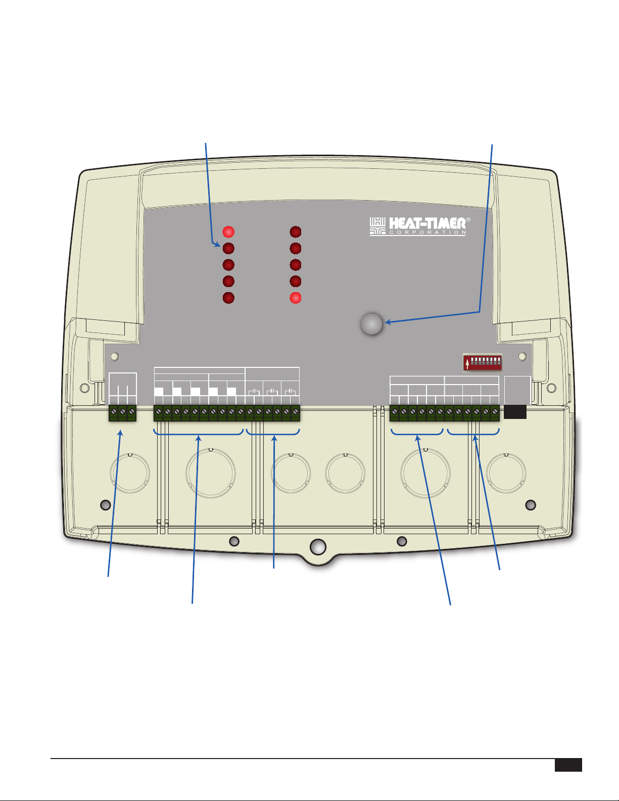
PLL LAYOUT
LED indicates the
associated relay status. Alarm Reset Button
L
1
PWR
N
2
PUMP 1
PUMP 2
PUMP 3
VALVE 1
VALVE 2
OUTPUT RATINGS:
MAXIMUM 6A TOTAL FOR ALL CIRCUITS
INPUT RATINGS: 120VAC 60Hz, 12VA MAX.
CAUTION:
Wire all circuits as Class I or Electric Ligh and Power Circuits.
OUTPUT (SOURCING 120VAC)
P1
G
L
3
N
4 5
2A RESISTIVE, 120VAC
1/4 HP, 120VAC 60Hz, Pilot Duty 80VA, 120VAC
Risk of Electric Shock. Use Copper Conductors Only.
PUMPS
P2 P3
L
N
6 7 8 9
N
L
VALVES
V1 V2
L
L
N
10 11 12 13
ALARMS
A1
N
14
15
16
ALARM 1
ALARM 2
ALARM 3
PUMP LEAD-LAG
PLL
COM
POWER
ALARM
RESET
DIP SWITCHES
DO NOT APPLY ANY VOLTAGE
TO INPUT TERMINALS
A2
A3
17
18
19
PUMP CALL FLOW INPUTS
C1 C2 C3 F1 F2 F3
20
21
23
24
22
On
1 2 3 4 5 6 7 8
RS-485
26
28
29
27
25
30
31
120 VAC
Power
Pump and Valve output relays
source 120 VAC power.
PLL Installation and Operation Manual
Alarm output relays
do not source power.
Pump Flow Inputs
(Dry-Contact)
Pump Call Inputs
(Dry-Contact)
HT# 059296-00A
3
OVERVIEW
The PLL is a Lead-Lag Pump control. It is designed to operate in different modes to satisfy multiple pumping applications. To
change the operating mode, set the dip switches. See "Dip Switches" on page 10. It can provide pump lead-lag rotation for two or
three pump systems. With its built-in alarm outputs, the PLL can trigger an alarm whenever a pump fails to provide proof-of-ow
within 30 seconds. It can also be used to provide pump ow check and run-on delay.
The PLL can operate up to 3 pumps. It outputs source 120 VAC power to its pump and solenoid valve outputs. However, alarm
outputs require an external power source.
ALARMING
• The PLL is equipped with an alarm output for each of the three available pump outputs.
• For local indication, it also has an LED for each of the alarm outputs.
Alarming on No-Flow
• If a pump fails to provide proof-of-ow for 30 seconds, by shorting the Flow input terminals, the PLL will turn that pump’s alarm
output on and blink its alarm LED.
• If the mode selected offers a rotation option, then the PLL shall turn on the next pump output and its LED.
Ending the Alarm
• If any of the pumps is in alarm, its alarm output will remain on until the Alarm Reset button is pressed. This will cause the Alarm
output to turn off.
ROTATION OPTIONS
• The PLL offers lead-lag pump rotation in many of its modes.
• When an operating mode has rotation options, it will have
multiple time-rotation options and an alternating rotation option.
• You can change the time interval of the time-rotation using
the appropriate dip switches for the mode selected. See "Dip
Switches" on page 10.
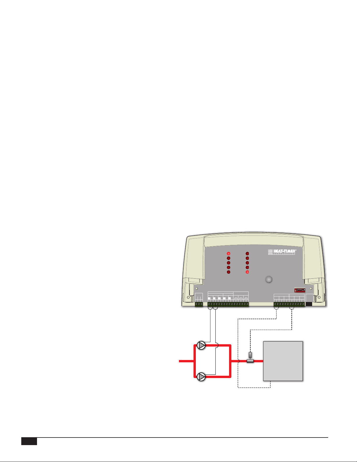
1-Call / 1-Flow (2-Pump Mode) or (3-Pump
Mode)
• This mode is designed to rotate two system pumps in a hydronic
application.
• The PLL rotates the pumps based on either timed rotation or
alternating demand (per call). The rotation options are selected
via dip switches.
• The pump call must be connected to Pump 1 input terminals
(C1) (20 and 21). In addition, the ow input must be connected
to Flow 1 input terminals (F1) (26 and 27).
• Alternating demand activates a different pump each time a pump
call is initiated.
• Timed rotation has two options, 1 day, and 7 days rotation.
• When rotation of the lead pump is to take place during a timed
rotation, the operation of both pumps, old lead pump and new
lead pump, will overlap for a few seconds to eliminate a no-ow
period prevent boiler short-cycling.
• In these modes, if a pump fails to provide proof-of-ow for a
period of 30 seconds, the PLL will turn it off. Also, it will turn
on its alarm and turn on the next lead pump.
Pump1
Pump2
OUTPUT RATINGS:
2 RESISTIVE, 120VAC
1/4 HP, 120VAC 60Hz, Pilot Duty 80VA, 120VAC
MAXIMUM 6A TOTAL FOR ALL CIRCUITS
INPUT RATINGS: 120VAC 60Hz, 12VA MAX.
CAUTION:
Risk of Electric Shock. Use Copper Conductors Only.
Wire all circuits as Class I or Electric Ligh and Power Circuits.
OUTPUT (SOURCING)
PUMPS
PWR
L
G
N
1
3
2
VALVES
P2 P3
P1
V1 V2
L
L
N
N
N
L
L
N
10 11 12 13
6 7 8 9
4 5
L
N
PUMP 1
PUMP 2
PUMP 3
VALVE 1
VALVE 2
ALARMS
A1
14
15
A2
16
17
ALARM 1
ALARM 2
ALARM 3
COM
POWER
A3
18
19
Flow
Switch
PLL
PUMP LEAD-LAG
ALARM
RESET
DO NOT APPLY ANY VOLTAGE
TO INPUT TERMINALS
PUMP CALL FLOW INPUTS
C1 C2 C3 F1 F2 F3
20
21
23
24
22
25
Boiler or
Heating Source
26
27
DIP SWITCHES
On
1 2 3 4 5 6 7 8
28
29
30
RS-485
31
HT# 059296-00A
4
PLL Installation and Operation Manual
1-Call, 2-Flow (2-Pump)
• This mode is designed to rotate two system pumps in a hydronic
application. It is primarily used with Variable Frequency Drive
(VFD) pumps.
• The operation of this mode is similar to the 1-Call/1-Flow
Mode listed previously. The only exception is that each pump
will have its own ow input. That means that pump call must
be connected to Pump 1 call input terminals (C1) (20 and 21).
Pump 1 ow input must be connected to Flow 1 input terminals
(F1) (26 and 27) and Pump 2 ow input must be connected to
Flow 2 input terminals (F2) (28 and 29).
AUXILIARY PUMP
VFD
Pump1
VFD
Pump2
OUTPUT RATINGS:
2 RESISTIVE, 120VAC
1/4 HP, 120VAC 60Hz, Pilot Duty 80VA, 120VAC
MAXIMUM 6A TOTAL FOR ALL CIRCUITS
INPUT RATINGS: 120VAC 60Hz, 12VA MAX.
CAUTION:
Risk of Electric Shock. Use Copper Conductors Only.
Wire all circuits as Class I or Electric Ligh and Power Circuits.
OUTPUT (SOURCING)
PUMPS
PWR
L
G
N
1
3
2
VALVES
P2 P3
P1
V1 V2
L
L
N
N
N
L
L
N
10 11 12 13
6 7 8 9
4 5
L
PUMP 1
PUMP 2
PUMP 3
VALVE 1
VALVE 2
A1
N
14
15
ALARMS
16
A2
17
ALARM 1
ALARM 2
ALARM 3
PUMP LEAD-LAG
COM
ALARM
POWER
RESET
A3
18
19
Boiler or
Heating Source
PLL
DO NOT APPLY ANY VOLTAGE
TO INPUT TERMINALS
PUMP CALL FLOW INPUTS
C1 C2 C3 F1 F2 F3
20
26
21
23
24
27
22
25
DIP SWITCHES
On
1 2 3 4 5 6 7 8
28
29
30
RS-485
31
2-Call, 2-Flow (3-Pump)
• This conguration is typically used in a two-Boiler Feed
application. It uses an Auxiliary pump / Pump 3 to replace any
failing boiler feed pump. It does that by turning on a normally
closed solenoid valve to direct the ow from the failing pump to
the auxiliary pump.
• No rotation is available in this mode. The PLL control operates
a single pump per boiler.
• A maximum of two boiler pumps can be connected to a single
PLL.
• If any of the boiler pumps fail to provide proof-of ow in 30
seconds, the PLL will switch its operation to the Auxiliary pump
/ Pump 3 (P3).
• The valve outputs are used to operate solenoid valves to switch
the system ow from the failed pump to the Auxiliary pump /
Pump 3 (P3). Valve 1 output (V1) is turned on when Pump 1
fails and goes into alarm. Valve 2 output (V2) is turned on when
Pump 2 fails and goes into alarm. See "Valve Output Wiring" on
page 9..
• If a pump fails, the PLL will turn it off and will turn on its Alarm
output, its Valve output, and the Auxiliary pump / Pump 3 (P3)
output. In addition, it will blink its Alarm LED.
• If the second pump fails for over 30 seconds while the rst
pump is in alarm, the PLL will turn off the 2nd pump and turn
on its relevant solenoid valve and Alarm LED. In this case, the
Auxiliary pump / Pump 3 (P3) replaces both primary pumps
until the situation is rectied and the Manual Reset button is
pressed.
OUTPUT RATINGS:
2 RESISTIVE, 120VAC
1/4 HP, 120VAC 60Hz, Pilot Duty 80VA, 120VAC
MAXIMUM 6A TOTAL FOR ALL CIRCUITS
INPUT RATINGS: 120VAC 60Hz, 12VA MAX.
CAUTION:
Risk of Electric Shock. Use Copper Conductors Only.
Wire all circuits as Class I or Electric Ligh and Power Circuits.
OUTPUT (SOURCING)
PUMPS
PWR
L
G
N
1
3
2
VALVES
P2 P3
P1
V1 V2
L
L
N
N
N
L
L
N
10 11 12 13
6 7 8 9
4 5
PUMP 1
PUMP 2
PUMP 3
VALVE 1
VALVE 2
A1
L
N
14
15
Flow
Switch 2
Pump 2
ALARMS
16
A2
A3
17
18
19
Boiler 2
ALARM 1
ALARM 2
ALARM 3
COM
POWER
ALARM
RESET
PLL
PUMP LEAD-LAG
DO NOT APPLY ANY VOLTAGE
TO INPUT TERMINALS
PUMP CALL FLOW INPUTS
C1 C2 C3 F1 F2 F3
20
26
21
23
24
27
22
25
Flow
Switch 1
Solenoid 1Solenoid 2
Aux Pump 3
DIP SWITCHES
On
1 2 3 4 5 6 7 8
28
29
30
Boiler 1
RS-485
31
Pump 1
PLL Installation and Operation Manual
HT# 059296-00A
5

PUMP DELAY
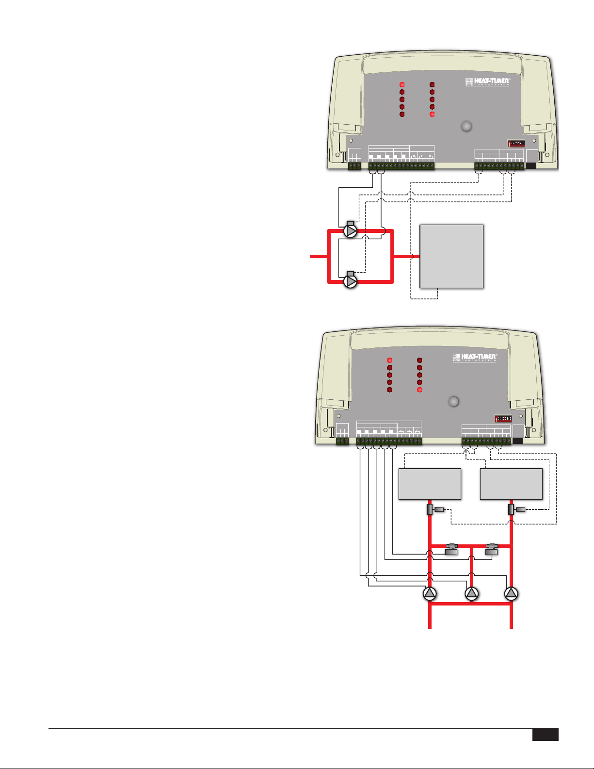
3-Call, 3-Flow (3-Pump)
• This conguration is typically used in one, two, or three boiler
pump applications to offer pump delay and alarming. The PLL
control operates a single pump per boiler.
• Each of the pump calls will use a different pump call input (C1,
C2, and C3).
• Also, each of the pump ows will use the respective pump ow
input (F1, F2, and F3).
• No rotation is available in this mode.
• If a pump failed to provide proof-of-ow for over 30 seconds,
the PLL will turn that pump output off and turn on its alarm.
OUTPUT RATINGS:
2 RESISTIVE, 120VAC
1/4 HP, 120VAC 60Hz, Pilot Duty 80VA, 120VAC
MAXIMUM 6A TOTAL FOR ALL CIRCUITS
INPUT RATINGS: 120VAC 60Hz, 12VA MAX.
CAUTION:
Risk of Electric Shock. Use Copper Conductors Only.
Wire all circuits as Class I or Electric Ligh and Power Circuits.
OUTPUT (SOURCING)
PUMPS
PWR
L
G
N
1
3
2
VALVES
P2 P3
P1
V1 V2
L
L
N
N
N
L
L
N
10 11 12 13
6 7 8 9
4 5
PUMP 1
PUMP 2
PUMP 3
VALVE 1
VALVE 2
L
N
ALARM 1
ALARM 2
ALARM 3
COM
POWER
ALARMS
A1
A2
A3
14
15
16
17
18
19
PLL
PUMP LEAD-LAG
ALARM
RESET
DO NOT APPLY ANY VOLTAGE
TO INPUT TERMINALS
PUMP CALL FLOW INPUTS
C1 C2 C3 F1 F2 F3
20
21
23
24
22
25
26
DIP SWITCHES
28
27
On
1 2 3 4 5 6 7 8
29
RS-485
30
31
Boiler 1 Boiler 2
Flow
Switch 1
Pump 1
Flow
Switch 2
Pump 3Pump 2
Boiler 3
Flow
Switch 3
PUMP EXERCISE
• This option is recommended for all pumps as it helps protect the pumps from locking due to sediment deposit and rust in the
system. It proves very benecial to wet rotor pumps as it helps lubricate their seals.
• When this feature is enabled, The PLL exercises any pump that did not run for a week. The exercise period is 10 seconds.
INSTALLATION STEPS
Follow these steps to make sure that all aspects of the system installation are done:
1. Mount the PLL control. See "Mounting The Enclosure" on page 7.
2. Wire the PLL control to the power, the pumps, ow inputs, valves, and the alarms. See "Wiring" on page 8.
3. Set the dip switches to match your application. See "Dip Switches" on page 10..
4. Power the control.
HT# 059296-00A
6
PLL Installation and Operation Manual
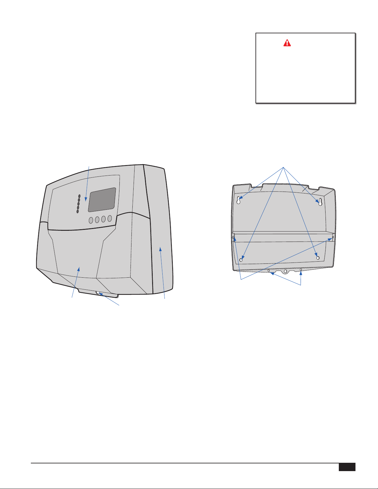
INSTALLATION
MOUNTING THE ENCLOSURE
• Select a location near the equipment to be controlled.
• The surface should be at and sufciently wide and strong to hold the PLL.
• Keep the control away from extreme heat, cold, or humidity. Ambient operating
temperature is from 20 to 120°F.
• Remove the Enclosure Wiring Cover from the control enclosure by removing the
two bottom screws.
• Remove the Enclosure Display Module by removing its Mounting Screws.
• Screw the Enclosure Base to the surface through the upper and lower mounting
holes on the back of the enclosure.
• Replace the Enclosure Display Module and its Mounting Screws.
• Do not replace the Enclosure Wiring Cover until all wiring is done.
• When purchasing a padlock for the enclosure, the maximum shank diameter should
not exceed ¼”
Warning
The PLL is an operating control
only not a safety control. It is
the responsibility of the installer
to verify that all the safety and
limits required by code are
working properly before and
after the PLL is installed.
Enclosure Display Module
Enclosure Wiring Cover Enclosure Base
Hole for optional lock
(not supplied)
Mounting Holes
Display Mounting Screws
Wiring Cover
Mounting Screws
PLL Installation and Operation Manual
HT# 059296-00A
7
WIRING
1 2 3 4 5 6 7 8
On
DO NOT APPLY ANY VOLTAGE
TO INPUT TERMINALS
10 11 12 13
14
15
16
17
18
19
RS-485
VALVES
A1
A2
A3
24
20
22
21
23
25
29
27
26
28
30
CAUTION:
Risk of Electric Shock. Use Copper Conductors Only.
Wire all circuits as Class I or Electric Ligh and Power Circuits.
2A RESISTIVE, 120VAC
1/4 HP, 120VAC 60Hz, Pilot Duty 80VA, 120VAC
OUTPUT RATINGS:
ALARM 2
ALARM 3
COM
POWER
ALARM 1
PUMP 2
PUMP 3
VALVE 1
VALVE 2
PUMP 1
ALARM
RESET
PLL
PUMP LEAD-LAG
MAXIMUM 6A TOTAL FOR ALL CIRCUITS
INPUT RATINGS: 120VAC 60Hz, 12VA MAX.
DIP SWITCHES
31
C1 C2 C3 F1 F2 F3
PUMP CALL FLOW INPUTS
ALARMS
V1 V2
L
NLN
6 7 8 9
P2 P3
L
N
4 5
P1
L
N
L
N
PUMPS
OUTPUT (SOURCING 120VAC)
1 2 3 4 5 6 7 8
On
DO NOT APPLY ANY VOLTAGE
TO INPUT TERMINALS
RS-485
29
27
26
28
30
ALARM
RESET
PLL
PUMP LEAD-LAG
DIP SWITCHES
31
F1 F2 F3
FLOW INPUTS
1 2 3 4 5 6 7 8
On
DIP SWITCHES
Warning
Class 1 voltage wiring (low voltage) must use a different knockout
and conduit from any Class 2 voltage wiring (high voltage).
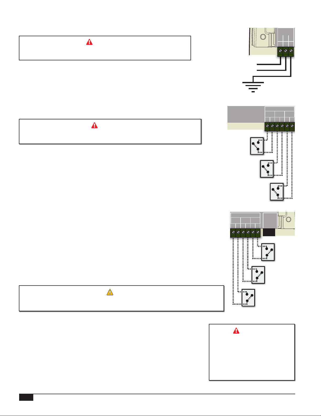
WIRING THE POWER
• Bring the power wires through one of the bottom knockouts of the enclosure.
• Attach 120V 60 Hz wires to their respective Line, Neutral, and Ground terminals.
• Heat-Timer recommends the installation of a Surge Suppressor and a Power Switch
before the Power Line connection for safety and ease of service.
120 VAC
Earth
Ground
N
PWR
L
G
N
1
3
2
L
INPUT WIRING
Warning
All of the PLL inputs are dry-contact only. DO NOT APPLY POWER TO
ANY INPUT as this may damage the control and void its warranty.
Pump Call Input Wiring
Pump Call (C1 Terminal 20 and 21), (C2 Terminal 22 and 23), (C3 Terminal
24 and 25)
• Depending on the mode selected, the PLL may require the use of one, two, or three
Pump Call inputs. See "Dip Switches" on page 10.
• Wire each Pump input into the corresponding input terminals of the PLL. See
"Overview" on page 4.
Flow Input Wiring
Pump Flow (F1 Terminal 26 and 27), (F2 Terminal 28 and 29), (F3 Terminal
30 and 31)
• Depending on the mode selected, the PLL may require the use of one, two, or three
ow inputs. See "Overview" on page 4.
• Wire each Flow input to the corresponding input terminals of the PLL.
• If a pump fails to provide a ow signal for over 30 seconds, by shorting the proper
ow input terminal, the PLL will turn off the failing pump’s output and LED and turn
on the its pump alarm output and LED.
• If the mode selected rotates the lead pump or offers an auxiliary pump operation,
the failed pump alarm will cause the lead pump to go the next available pump or the
auxiliary pump.
If no ow switch is used, use a jumper on the ow input terminals. (Heat-Timer
OUTPUT WIRING
• The PLL provides 120 VAC 60Hz power to the pump and solenoid valve output
relays. Each relay can power up to 1/4 HP pump (120 VAC 60 Hz) or 80 VA Solenoid
Valves (120 VAC 60Hz).
• The PLL does not provide power to the alarm output relays. A separate power source
must supply the power to the alarm. In this case, the alarm relays act as a power
switches.
ALERT
recommends using a ow switch for better system response and operation.
C1 C2 C3
20
Pump 1
Call
Input
Pump 2
Call
Input
Pump 3
Call
Input
FLOW INPUTS
F1 F2 F3
26
28
29
27
RS-485
30
31
Flow 2
Input
Warning
Each of the Pump and Solenoid
valve outputs source 120 VAC.
If the pump used require more
used require more than 80 VA of
120 VAC, use a relay or a starter
than ¼ HP or if the solenoid
to prevent PLL damage.
Flow 1
Input
PUMP CALL
21
23
24
22
Flow 3
Input
25
HT# 059296-00A
8
PLL Installation and Operation Manual
 Loading...