

Installation and Operation Manual
Steam Outdoor Reset Boiler /Motorized
MPC
Valve Cycling Heating Control
R
C O R P O R A T I O N
MENU FUNCTIONS
SELECT enters menus or accepts changes
ADJUST selects menu items or changes settings
BACK returns to previous menu
DAY selects next day
PREV./NEXT steps through output status
AUTO
ENCLOSED
ENERGY
MANAGEMENT
EQUIPMENT
LISTED
99RA
OUTPUT RATINGS:
120VAC, 6A RESISTIVE
1A PILOT DUTY
15A TOTAL
FOR ALL CIRCUITS
INPUT RATINGS:
115VAC 60Hz
30VA MAX
USE COPPER WIRE,
CLASS 1 WIRE ONLY
BYPASS
OUTPUT SYS
2 3 4 5
MON 12/01/2010 10:01Am
Cycle On 13/15
Cutoff = 55
OD = 31
HELP NEXT
6 7 8 9 10 11 12 13 14 15 16 17
MPC
Platinum
o
F SYS = 138oF
PREV.
(DEL)
CLOCK
o
AUX
F Day
DAY
OPTION
1
OPTION
2
INPUTS
DO NOT APPLY ANY VOLTAGE
TO SENSOR TERMINALS
ALL SENSORS MUST BE
GOLD SERIES SENSORS
ADJUST
PRESS TO
SELECT
BACK
OPTION
3
18
Platinum
T
A1
SYSTEM
A2
A3
A4
A5
A6
A7
A8
A9
A10
A11
A12
A13
A14
A15
A16
A17
A18
TEMP
SHUTDOWN
PROVE
NETWORK
MSI CONNECTION
ON BACK
AUX
INPUT 0
T
OUT
TEMP
T
AUX
TEMP 0
T
AUX
TEMP 1
T
AUX
TEMP 2
LINE
SAFETY
GROUND
MUST BE
CONNECTED
MADE IN U.S.A.
NEUTRAL
WARNING
This Heat-Timer control is strictly an operating control; it should
never be used as a primary limit or safety control. All equipment
must have its own certified limit and safety controls required by local
codes. The installer must verify proper operation and correct any
safety problems prior to the installation of this Heat-Timer control.
MPC Platinum Installation and Operation Manual
B R W
MOTORIZED
VALVE
BURNER
SYSTEM AUX
CLOCK
OPTION1OPTION2OPTION
3
ROUTE SENSOR AND AUXILIARY WIRES
THROUGH THIS KNOCKOUT ONLY
HT# 059085-00 F
1

MPC Platinum Function Chart . . . . . . . . . . .3
Understanding the Cycle Concept. . . . . . . . .4
Sequence of operation . . . . . . . . . . . . . . . . 5
Cycle Timeline . . . . . . . . . . . . . . . . . . . . . 5
. . . . . . . . . . 6
Initial Program. . . . . . . . . . . . . . . . . . . . .6
Selecting the System Features . . . . . . . . . . . . 6
Making Sure You Have the Right Control . . . . . .7
Installation . . . . . . . . . . . . . . . . . . . . . . . 8
Mounting the enclosure . . . . . . . . . . . . . . . .8
Rear of Control. . . . . . . . . . . . . . . . . . . . . 8
Sensor Installation. . . . . . . . . . . . . . . . . . . 9
Outdoor Sensor Installation . . . . . . . . . . . . . . 9
Heating System Sensor (HSS) Installation . . . . . .9
Wiring the power. . . . . . . . . . . . . . . . . . . 10
Output Wiring . . . . . . . . . . . . . . . . . . . . 10
Wiring To a motorized valve . . . . . . . . . . . . . 10
Wiring To a Boiler . . . . . . . . . . . . . . . . . . 10
Wiring To System Output. . . . . . . . . . . . . . . 11
Wiring to Auxiliary Clock . . . . . . . . . . . . . . . 11
Wiring to Option Outputs. . . . . . . . . . . . . . . 11
Input Wiring . . . . . . . . . . . . . . . . . . . . . 12
Wiring System Sensor . . . . . . . . . . . . . . . . 12
Wiring the Outdoor Sensor. . . . . . . . . . . . . . 12
Wiring the Shutdown . . . . . . . . . . . . . . . . . 12
Wiring The Prove. . . . . . . . . . . . . . . . . . . 12
Network and Aux Temp . . . . . . . . . . . . . . . 12
Testing the Sensors . . . . . . . . . . . . . . . . . 13
Aux Input . . . . . . . . . . . . . . . . . . . . . . . 13
Wiring Network Sensors . . . . . . . . . . . . . . . 13
Connecting Wireless Sensor System . . . . . . . . 13
Remote Communication Wiring . . . . . . . . . . 14
BACnet Wiring . . . . . . . . . . . . . . . . . . . . 14
BACnet IP Wiring . . . . . . . . . . . . . . . . . . 14
BACnet MS/TP Wiring . . . . . . . . . . . . . . . . 14
MODBUS RTU Wiring . . . . . . . . . . . . . . . . 15
Internet Wiring . . . . . . . . . . . . . . . . . . . . 15
Ethernet Connection to Modem . . . . . . . . . . . 15
Ethernet Connection to Platinum Control . . . . . . 15
DHW Energy Saver Wiring . . . . . . . . . . . . . 15
AUTO/BYPASS Switch. . . . . . . . . . . . . . . . 16
Setting the Control . . . . . . . . . . . . . . . . . 16
Display and Changing Settings. . . . . . . . . . . 16
menu Types . . . . . . . . . . . . . . . . . . . . . 16
Display Messages . . . . . . . . . . . . . . . . . . 17
Menu Settings . . . . . . . . . . . . . . . . . . . . 18
Startup Settings . . . . . . . . . . . . . . . . . . . 20
Sensor Type . . . . . . . . . . . . . . . . . . . . . 20
Operation Mode . . . . . . . . . . . . . . . . . . . 20
Cycle Length . . . . . . . . . . . . . . . . . . . . . 20
Sensor Fault . . . . . . . . . . . . . . . . . . . . . 20
Day light saving mode . . . . . . . . . . . . . . . . 21
Option Outputs Modes . . . . . . . . . . . . . . . 21
Option relay 1 mode . . . . . . . . . . . . . . . . . 21
Option 2 Relay Mode . . . . . . . . . . . . . . . . 21
Option 3 relay mode . . . . . . . . . . . . . . . . . 21
DHW Supply and return Defaults . . . . . . . . . . 22
Setting the Date and Time . . . . . . . . . . . . . . 22
HT# 059085-00 F
2
Content
Operation. . . . . . . . . . . . . . . . . . . . . . . 23
System Settings . . . . . . . . . . . . . . . . . . . 23
Season . . . . . . . . . . . . . . . . . . . . . . . . 23
Day and Night Heat Adjustment . . . . . . . . . . . 23
Cycle Length Table. . . . . . . . . . . . . . . . . . 24
Boost Mode . . . . . . . . . . . . . . . . . . . . . 26
Vari Boost Curves . . . . . . . . . . . . . . . . . . 26
Early Shutdown Curves . . . . . . . . . . . . . . . 27
Warm-up Enable and Learn . . . . . . . . . . . . . 27
System Run-On . . . . . . . . . . . . . . . . . . . 28
Thermal Lockout . . . . . . . . . . . . . . . . . . . 28
Space Lockout . . . . . . . . . . . . . . . . . . . . 28
Day and Night Space Targets . . . . . . . . . . . . 28
Schedules . . . . . . . . . . . . . . . . . . . . . . 29
Setting the DAY/NIGHT Schedule . . . . . . . . . . 29
Copy Schedule. . . . . . . . . . . . . . . . . . . . 30
Vacation Schedule Setting . . . . . . . . . . . . . . 30
Aux Relay Schedule . . . . . . . . . . . . . . . . . 30
Maintenance . . . . . . . . . . . . . . . . . . . . . 31
System and Outdoor Sensor Trim . . . . . . . . . 31
Fast Cycle . . . . . . . . . . . . . . . . . . . . . . 31
Password and Local Security. . . . . . . . . . . . 31
DHW Settings . . . . . . . . . . . . . . . . . . . . 32
Using the Supply/Return Sensor. . . . . . . . . . . 32
Supply/Return Set Point . . . . . . . . . . . . . . . 32
Supply/Return Peak/Light Differential . . . . . . . . 32
DHW Demand Schedule . . . . . . . . . . . . . . . 33
DHW Copy Schedule . . . . . . . . . . . . . . . . 33
Shift . . . . . . . . . . . . . . . . . . . . . . . . . . 33
Communication Options. . . . . . . . . . . . . . 34
Internet Communication Features . . . . . . . . . 34
Internet Communication. . . . . . . . . . . . . . . 35
Internet ID . . . . . . . . . . . . . . . . . . . . . . 35
Internet Port forwarding Table . . . . . . . . . . . . 35
BACnet Communication Features . . . . . . . . . 37
BACnet Communication
Selecting BACnet IP or BACnet MSTP . . . . . . . 37
. . . . . . . . . . . . . . 37
BACnet Device ID . . . . . . . . . . . . . . . . . . 37
IP and Mask Addresses . . . . . . . . . . . . . . . 37
. . . . . . . . . . . . 37
BACnet Device ID . . . . . . . . . . . . . . . . . . 37
MS/TP Address/ MAC Address . . . . . . . . . . . 38
MSTP Baud rate . . . . . . . . . . . . . . . . . . . 38
MPC Platinum BACnet Variable List . . . . . . . . . 38
BACnet PICS Statement . . . . . . . . . . . . . . . 40
MODBUS Communication Features . . . . . . . . 41
. . . 41
MODBUS Communication Options . . . . . . . . . 41
MAC
Address . . . . . . . . . . . . . . . . . . . . 41
MODBUS Baud . . . . . . . . . . . . . . . . . . . 41
MPC Platinum MODBUS Variable List. . . . . . 41
Troubleshooting. . . . . . . . . . . . . . . . . . . 43
Diagrams . . . . . . . . . . . . . . . . . . . . . . . 45
Warranty . . . . . . . . . . . . . . . . . . . . . . . 54
. . . . . . . . . . . . . . . . . . . 56
MPC Platinum Installation and Operation Manual
. . . . . . . . . . . . . . . 37
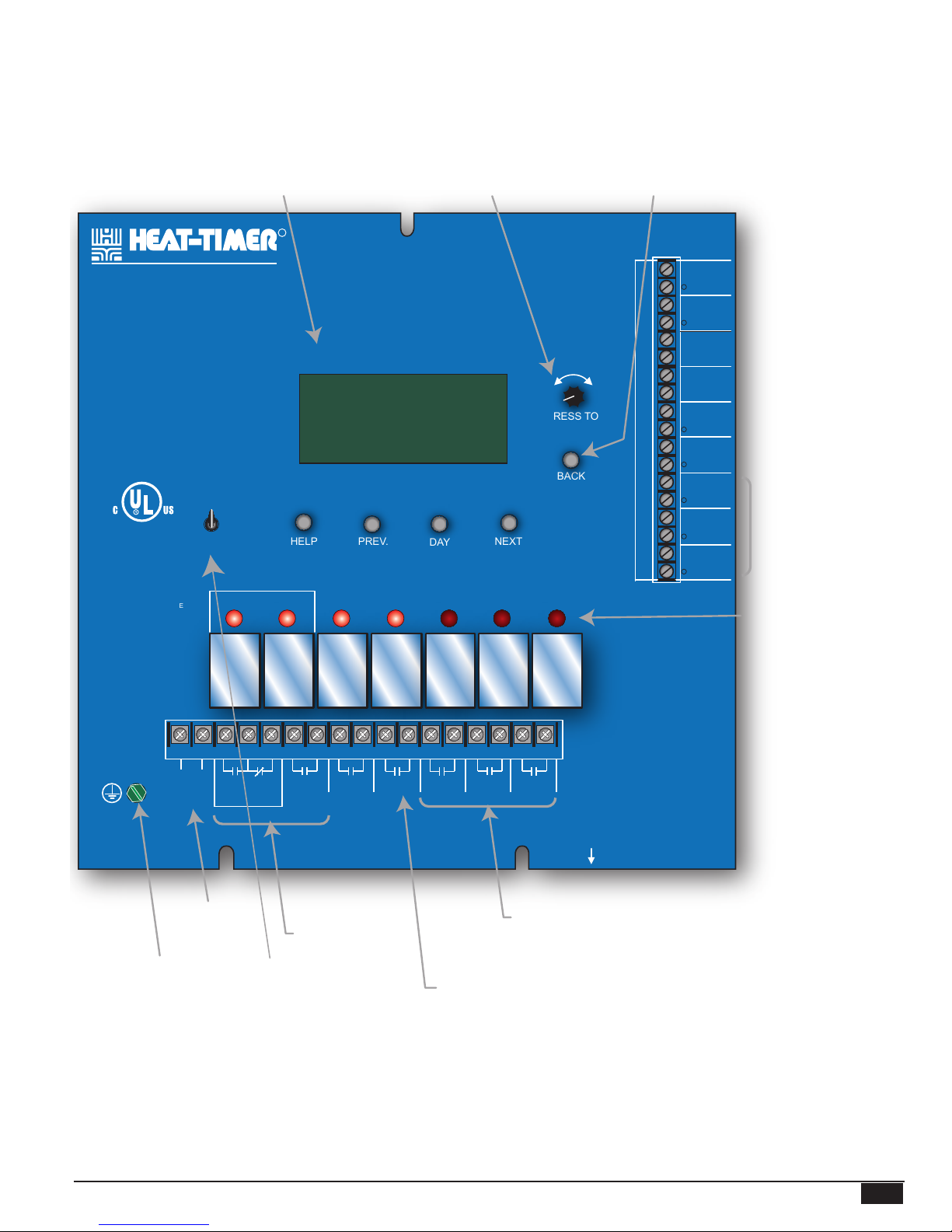
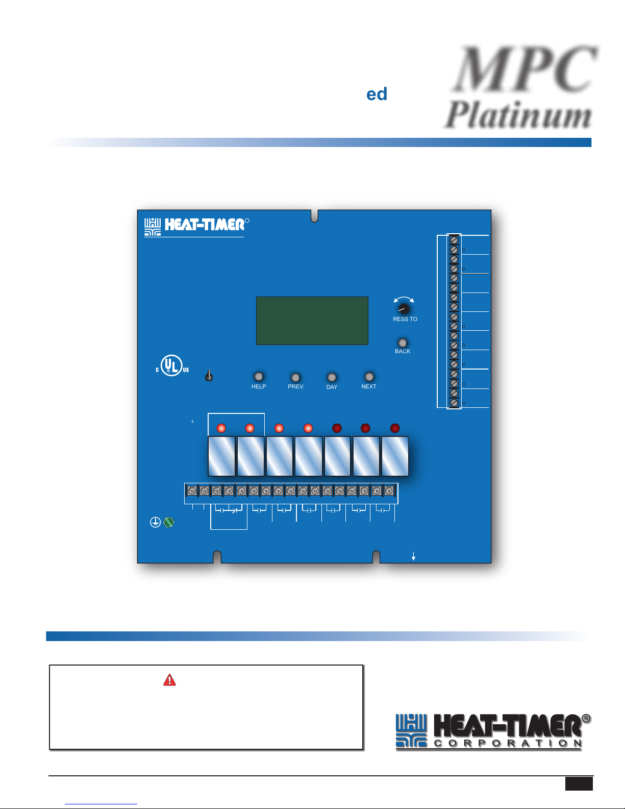
MPC PLATINUM FUNCTION CHART
Digital display shows the cycle status,
outdoor cutoff, outdoor, and system temperatures.
To view and adjust settings, press the
Adjust/Select button.
R
C O R P O R A T I O N
MENU FUNCTIONS
SELECT enters menus or accepts changes
ADJUST selects menu items or changes settings
BACK returns to previous menu
DAY selects next day
PREV./NEXT steps through output status
AUTO
ENCLOSED
ENERGY
MANAGEMENT
EQUIPMENT
LISTED
99RA
OUTPUT RATINGS:
120VAC, 6A RESISTIVE
1A PILOT DUTY
15A TOTAL
FOR ALL CIRCUITS
INPUT RATINGS:
115VAC 60Hz
30VA MAX
USE COPPER WIRE,
CLASS 1 WIRE ONLY
BYPASS
OUTPUT SYS
2 3 4 5
MON 12/01/2010 10:01Am
Cycle On 13/15
Cutoff = 55
OD = 31
HELP NEXT
6 7 8 9 10 11 12 13 14 15 16 17
Depress the knob to move
forward through the menus and to
accept changes. To change a
setting's value, rotate the knob.
MPC
Platinum
o
F Day
o
F SYS = 138oF
PREV.
(DEL)
CLOCK
AUX
DAY
OPTION
Depress the button to go back
through the menus
T
INPUTS
DO NOT APPLY ANY VOLTAGE
TO SENSOR TERMINALS
ALL SENSORS MUST BE
GOLD SERIES SENSORS
ADJUST
PRESS TO
SELECT
BACK
OPTION
1
OPTION
2
3
A1
A2
A3
A4
A5
A6
A7
A8
A9
A10
A11
A12
A13
A14
A15
A16
A17
A18
SYSTEM
TEMP
SHUTDOWN
PROVE
NETWORK
MSI CONNECTION
ON BACK
AUX
INPUT 0
T
OUT
TEMP
T
AUX
TEMP 0
T
AUX
TEMP 1
T
AUX
TEMP 2
From heating system sensor
When closed, outputs
are turned off*
Checks status of system
components*
From Heat-Timer network
sensors**
From DHW Control*
From outdoor sensor
mounted in the shade
Remote Communication
Option**
Red lights indicate when the
associated stage relay
is activated
18
SAFETY
GROUND
MUST BE
CONNECTED
MADE IN U.S.A.
LINE
NEUTRAL
120VAC
Power
B R W
MOTORIZED
VALVE
BURNER
Valve and Burner
Outputs are active
when MPC requires
steam
Green Earth
Ground screw
BYPASS position runs
the output.
* DRY CONTACT ONLY
** Only available with the Remote Communications package
MPC Platinum Installation and Operation Manual
SYSTEM AUX
CLOCK
OPTION1OPTION2OPTION
3
ROUTE SENSOR AND AUXILIARY WIRES
THROUGH THIS KNOCKOUT ONLY
OPTION outputs can be programmed
to operate additional equipment or
Internet Modem.
Operates additional equipment based
on a separate Aux Schedule
HT# 059085-00 F
3

UNDERSTANDING THE CYCLE CONCEPT
The Heat-Timer MPC Platinum is a microprocessor-based control designed to manage a low-pressure steam heating system. It
operates a steam boiler or a two-way steam valve to provide the desired amount of heat to the building.
The MPC Platinum operates based on the CYCLE principle. Heat-Timer created this principal specically for steam heating
systems to overcome the inabilities of standard thermostatic controls to cope with the unique challenges of low-pressure steam
heating. Unlike water and air systems, steam systems take time to build up a "head of steam". Moreover, once the system starts
heating up, it has momentum that takes time to dissipate. This makes it difcult to control its temperature.
60 Minute Cycle
(Cycle-On=21 + Cycle-O=39)
Establish
Heat
Cycle-On
21 Minutes
Cycle-Off
39 Minutes
Cycle delayed until
System Temperature drops
below System Set Point-Diff
Establish
Heat
Cycle-On
21 Minutes
Cycle length based on outdoor temperature
By monitoring the outside temperature, the MPC Platinum is able to anticipate the building heating needs. Each CYCLE period
(usually 60 minutes long, but adjustable depending on the type of radiation units) consist of a Cycle-ON segment and a Cycle-OFF
segment. The length of the Cycle-ON segment will vary with the outside temperature. The colder it is outside, the longer the
Cycle-ON part.
MPC Platinum
R
Zone C
Zone A
Zone B
C O R P O R A T I O N
MENU FUNCTIONS
SELECTenters menus or accepts changes
ADJUSTselects menu items or changes settings
BACK returns to previous menu
DAY selects next day
PREV./NEXT steps through output status
AUTO
BYPASS
MON 12/28/04 10:43Am
Cut= 55
OD= 31
HELP NEXT
OUTPUT
2 3 4 5 6 7 8 9 11 12 13 14 15 16 17
R W
B
LINE
MOTORIZED
VALVE
NEUTRAL
Platinum
PREV.
Cycle On
o
F SYS= 148oF
(DEL)
BURNER
MPC
o
F Day
DAY
AUX
CLOCK
SYS
10 18
SYSTEM OPTION1OPTION2OPTION3AUX
CLOCK
T
A1
INPUTS
SYSTEM
TEMP
A2
DO NOT APPLY ANY VOLTAGE
TO SENSOR TERMINALS
A3
SHUTDOWN
A4
ALL SENSORS MUST BE
GOLD SERIES SENSORS
A5
PROVE
A6
ADJUST
A7
NETWORK
MSI CONNECTION
A8
ON BACK
A9
AUX
PRESS TO
INPUT 0
A10
SELECT
T
A11
OUT
TEMP
A12
BACK
A13
T
AUX
TEMP 0
A14
T
A15
AUX
TEMP 1
A16
T
A17
AUX
TEMP 2
A18
OPTION1OPTION
OPTION
2
3
Outdoor
Sensor
Optional Location:
ROUTE SENSOR AND AUXILIARY WIRES
THROUGH THIS KNOCKOUT ONLY
System Sensor
At Furthest Radiator
System Sensor
Installed on Dry
Boiler Water Line
Return Above
Water Line
Boiler
Burner
Condensate
Receiver
The MPC Platinum constantly checks the outside temperature by means of a solid-state sensor located on the exterior of the
building. At the same time, it monitors the heating system of the building by means of a heating system sensor. This heating system
sensor is located where it will show that heat has reached the furthest location in the building (or the hardest to heat area). Based on
this combined data, the MPC Platinum sends instructions to the heating plant to control the heat level in the building.
In addition to adjusting the length of the Cycle-ON segment, the outdoor temperature acts as a system cutoff. When the outdoor
temperature rises above one of the adjustable cutoff temperatures (Two outdoor cutoffs are available. One is for the day and the
other is for the night), the MPC Platinum will not call for any heat. When the outdoor temperature drops below the cutoff, the
MPC Platinum will automatically begin controlling the heating cycle. Once the heating system is active, the heating system sensor
will register when heat has reached throughout the building. The combined effect of these two sensors is to provide an even,
comfortable level of heat throughout the building.
HT# 059085-00 F
4
MPC Platinum Installation and Operation Manual
Sample Mild Weather Cycle
Establish
Heat
Establish
Heat
Cycle-On
Heat On Heat Off
8 Minutes
Cycle-On
21 Minutes
Cycle-Off
52 Minutes
Cycle Length 60 minutes
Cycle-Off
39 Minutes
Sample Cold Weather Cycle
The MPC Platinum is able to maintain two different heat levels. The Day heat level is the higher level of heat. It provides
comfortable temperatures when the building tenants are active. The Night heat level provides lower heat and conserves energy when
the building is empty or when tenants are asleep. Both heat levels rely on the identical cycle concept, but the lower Night settings
provide less heat given the same outdoor temperature.
SEQUENCE OF OPERATION
• The MPC Platinum activates the steam source when the outside temperature falls below the outdoor sensor cutoff (factory set at
55°F for Day and 40°F for Night, but fully adjustable).
• The MPC Platinum will continue to call for heat, keeping the steam source active, until the heating system sensor reaches its
adjustable Set Point. This indicates that steam has gotten entirely through the system, or that "heat is established".
• Once "heat is established", the Cycle-ON segment of the cycle will begin.
• During the Cycle-ON period, the MPC Platinum will keep the steam source activated. The length of the ON part of the cycle
is dependent on the outdoor temperature, the Day/Night setting, and several user selectable adjustments that can be tuned to the
specic heat loss characteristics of the building.
• Once the Cycle-ON part has ended, the Cycle-OFF part of the cycle will begin. The MPC Platinum will turn off the boiler or
close the steam valve for the remainder of this cycle.
• When the Cycle-OFF part is over, the MPC Platinum will once again activate the steam source unless either the outside
temperature has risen above the cuttoff, or the thermal lockout is active.
• With the thermal lockout, the heating system sensor temperature must fall below the Set Point through an adjustable differential
before the heating source can be reactivated. This allows residual heat in the pipes to continue to heat the building. Once the
pipes have cooled sufciently, a new cycle can begin.
• However, if the MPC Platinum is an Internet capable control and space sensors are installed, the control checks for Space Lockout
before staring another cycle.
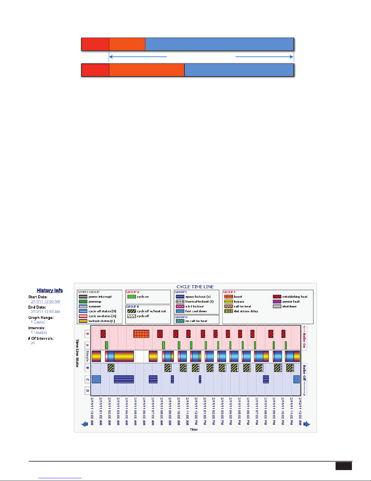
CYCLE TIMELINE
Internet Control Cycle Timeline view
MPC Platinum Installation and Operation Manual
HT# 059085-00 F
5

• During a heating cycle, the control switches between the different cycle states. The states are divided into groups.
• During any of the operational states, the control has the output relays energized. And during the energy saving states, the control
has the output relays de-energized.
• An Internet control Cycle Timeline is viewable on the History tab of the ICMS site. They are part of the Stock History.
• State Groups are divided into either Boiler-On or Boiler-Off. The Boiler-On groups are represented by the reddish background.
They are graphed on the upper portion of the Cycle-Timeline Internet history graph. The Boiler-Off groups are graphed on the
bottom portion of the graph and has a bluish background.
• These Internet graphs help troubleshoot and ne tune the control operation.
TYPICAL STEAM HEAT CONFIGURATION
The MPC Platinum works with virtually any non-vacuum steam heated system. The MPC Platinum can control a boiler directly to
create steam. For systems where a central plant provides steam, the MPC Platinum opens or closes a motorized valve to allow or
prevent steam from entering the heating system. The MPC Platinum also works with one or two-pipe steam systems.
However, based upon the specic layout of the steam heating system there are several differences in locating the heating system
sensor and in the output wiring to the boiler or motorized valve that the user need to observe. It is important to carefully check the
piping diagrams at the end of this manual to determine which of the following four layouts matches your heating system:
• One Pipe Steam - Motorized Valve
• Two Pipe Steam - Motorized Valve
• One Pipe Steam - Direct Burner Operation
• Two Pipe Steam - Direct Burner Operation
For subatmospheric vacuum type steam systems, see Heat-Timer SRC Platinum Control on the Heat-Timer web site
(http://www.heat-timer.com).
INITIAL PROGRAM
Setting an Initial Program ease's the conguration of the MPC Platinum while giving the opportunity to utilize many of the energy
saving and comfort features. The program should consist of the following:
• Select the features your system can utilize,
• Make sure you have the right control and accessories,
• Install the Control,
• Set the System Startup,
• Set the System Settings,
• Set the Schedules
• Adjust the Day and Night Heat Adjustments and the Set Point
SELECTING THE SYSTEM FEATURES
Heat-Timer designed the MPC Platinum with low-pressure steam building heating as the primary purpose. With this in mind, the
user can use many of the control features to ease, enhance, and improve the system performance. Below is a list of its major features.
Steam Outdoor Reset
• The MPC Platinum regulates the amount of steam sent to the building based on the outdoor temperature. It uses the Cycle concept
based on the Day and Night Heat Adjustment and outdoor cutoffs to regulate the heat. The colder it gets, the longer the Cycle-On
runs. See "AUTO/BYPASS Switch" on page 16.
Night Setback
• Whenever the outdoor temperature falls below the Outdoor Cutoff, the MPC Platinum adjusts the Cycle-ON and Cycle-OFF ratio
to hold a constant Day or Night heat level. The Night heat level is for when the building is unoccupied or tenants are sleeping.
Day and Night Schedules
• The MPC Platinum has 4 Day and 4 Night settings for each day of the week. By setting a Schedule, Day and Night Heat
Adjustments, and Outdoor Cutoffs, you can save energy while providing comfortable heat to the building. The settings allow
the MPC Platinum to reduce the length of the steam Cycle-ON portion during the night or when building is unoccupied. See
"Schedules" on page 29.
HT# 059085-00 F
6
MPC Platinum Installation and Operation Manual

Vacation Schedule (Available with Internet Control Only)
• This feature gives the user the ability to provide a lower-than-night space target between two specied date-time combinations.
This provides additional savings for schools and ofce buildings to use in long holiday periods. See "Vacation Schedule Setting"
on page 30.
Space Sensor Feedback (Available with Internet Control Only)
• For better control and much more energy saving capabilities you can add wireless or wired space sensors to the MPC Platinum to
ne tune its operation and increase the system's overall efciency. When you add space sensors to the space average, the MPC
Platinum checks the space average before the beginning of each cycle to determine if the building is sufciently heated. See
"Space Lockout" on page 28.
System Output
• The system output relay connects to and operates a combustion air-damper or other boiler room equipment and it will energize
whenever there is a call for the boiler. In addition, if you connect the combustion air-damper's end-switch to the Prove input
terminals, it will stop the boiler from ring if the damper is not fully open. See "Installation" on page 8.
Boost and Early Shutdown
• The boost returns the building to its Day (Normal) heat level after Night (Setback) heat level. It does it by running the burner
or valve output for a period of time that depends on the outside temperature. It offers an adjustable curve parameter to tune its
operation to the specic building. See "Boost Mode" on page 26.
• The Early Shutdown feature shifts the Day schedule to Night Setback before the last Night Time setting for that day. The Early
Shutdown varies based on Outdoor temperature (OD). The warmer the Outdoor temperature the earlier the MPC Platinum shifts to
Night Setback. See "Early Shutdown Curves" on page 27.
Remote Communication
• The MPC Platinum is upgradable to Internet, BACnet IP, BACnet MSTP, or MODBUS communication to allow monitoring and
controlling of all of its functions from a remote location. Only the Internet communication package allows the MPC Platinum to
accept a variety of additional sensor inputs to monitor their status and provide web, E-Mail, or text message alarms under specied
adjustable conditions.
MAKING SURE YOU HAVE THE RIGHT CONTROL
If you need the MPC Platinum to do additional tasks that either are not listed or you do not know how to congure them,
contact Heat-Timer Corp. Sales Department either by Phone (973)575-4004, Fax (973) 575-4052, or over the web (visit
http://www.heat-timer.com).
MPC Platinum Installation and Operation Manual
HT# 059085-00 F
7
INSTALLATION
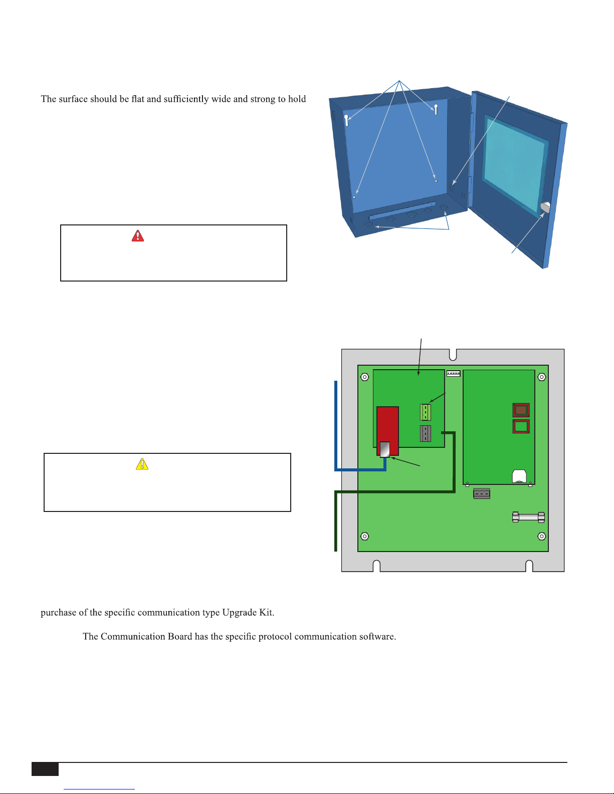
MOUNTING THE ENCLOSURE
• Select a location near the equipment to be controlled.
•
the MPC Platinum.
• Keep the MPC Platinum control away from extreme heat, cold, or
humidity. Ambient operating temperature is from 20 to 120°F.
• Remove the control from the metal enclosure by removing the top
center screw and loosening the two bottom screws. Then, lift the
control out of the enclosure.
• Screw the enclosure to the surface through its back mounting holes.
• Return the control to the enclosure, replace the top screw, and
tighten the bottom two screws.
WARNING
Use only the provided Enclosure Knockouts. DO
NOT DRILL HOLES THROUGH THE ENCLOSURE
AS IT WILL VOID CONTROL WARRANTY.
REAR OF CONTROL
Activate the Battery
• Turn the MPC Platinum control over to reveal the piggyback
circuit board (CPU board).
• Remove the plastic strap that covers the battery. The contacts
should be touching the battery.
• The control has a coin Lithium battery (CR2032)
(HT# 020002-00) that is used to maintain the control's date and
time during power outages. This battery can maintain the clock
for up to a total of 100 days.
Mounting Holes
Internet Communication Board (-RINet),
BACnet Communication Board (-BAC),
or MODBUS Communication Board (-BUS)
or the Internet
Communication
Board
Connect to BACnet IP Network
A(+)
G
B(-)
A(+)
G
B(-)
Wiring
Knockouts
MSI
Use Only
Communication
Knockout
Enclosure
Lock
CPU Board
ALERT
Do not install the battery unless you plan to keep the
control continuously powered. If the control has no power,
the battery will lose its charge in 100 days.
CAT5 Cable
RS485 Cable
Connect to BACnet MSTP Network
or MODBUS RTU Network
RJ45
Socket
Motherboard
RS485 (B)
Battery
Control Communication Upgrade
• All non-communication MPC Platinum controls are upgradable to any of the available communication options. This, requires the
• The Upgrade Kit consist of two boards, a CPU Board and a Communication Board. The CPU Board has the control operating
software.
• All communication boards have an Ethernet socket that is used for the BACnet IP or Internet communication and a RS485 socket
that is used for BACnet MS/TP or MODBUS communication.
• Both boards are mounted on the back of the Platinum control's motherboard. Thus, to install both boards you need to remove the
control from the enclosure by removing 3 facing screws. Then, turn the control over to reveal its back.
• Each of the boards is mounted on a group of standoffs that must be replaced during the upgrade. See "Remote Communication
Wiring" on page 14.
• Connect the communication cable from the side Knockout.
• Reinstall the Panel in the enclosure using 3 screws.
HT# 059085-00 F
8
MPC Platinum Installation and Operation Manual
SENSOR INSTALLATION
Outdoor Sensor
Shield
Immersion Well
3/8" ID 1/2" NPT
Immersion Heating System Sensor
Common Supply Pipe
Heating System
Sensor
Sensor Probe
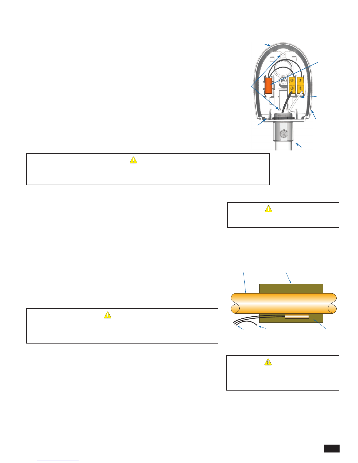
OUTDOOR SENSOR INSTALLATION
Only use the Heat-Timer sensor included with the unit (HT# 904220-00).
• Locate the sensor in the shade on the north side of the building. The sensor
should never be in direct sunlight.
• Be sure the location is away from doors, windows, exhaust fans, vents, or other
possible heat or cool sources.
• The sensor should be mounted approximately 10’ feet above ground level.
• Adhere the Outdoor Label provided to the back of the sensor base.
• Use the Enclosure Base bottom knockout for the conduit. Use the locknut to hold
the conduit and enclosure base together. Screw the cover to the base.
• Make sure to seal around the sensor enclosure and wall except from the bottom.
• The sensor wires can be extended up to 500’ using shielded 2-conductor cable
(HT# 703001-01) (#18/2). Do not connect the shield at the sensor. However,
connect it at the control using the terminal marked with an “O”.
• Do not run sensor wires in conduit with line voltage wiring.
Determining the proper location for the Outdoor Sensor is very important. The MPC Platinum will
base the heat on the outdoor temperature information it receives from this location. If the sensor is in
the sun, or covered with ice, its reading will be different from the actual Outdoor temperature (OD).
HEATING SYSTEM SENSOR (HSS) INSTALLATION
• Install the sensor at one of the following locations:
The ideal location for the HSS is on the furthest radiator in the system. This
radiator is usually the hardest to heat.
The sensor may be located on the furthest return riser. However, the sensor
MUST be above the boiler water line (on a dry return).
• Only use the sensor provided with the control. If you are replacing an earlier
Gold model Heat-Timer, it is NOT necessary to upgrade the sensor.
• Strap the HSS to the pipe using the tie-wraps provided with the outdoor sensor.
Then wrap insulation around the sensor and pipe to achieve the highest accuracy.
• The sensor wires can be extended up to 500' using a shielded 2-conductor cable
(HT# 703001-01) (#18/2).
• Do not connect the shield at the sensor. However, connect it at the control using
the terminal marked with an “O”.
• Do not run sensor wires in conduit or trough with line voltage wiring.
ALERT
Seal around
sensor and wall
Mounting
screws
location
Outdoor
drip-hole
on back of Sensor
Conduit
ALERT
NEVER Install the HSS between the
condensate receiver and the boiler.
Strap-On Heating System Sensor
Common Supply Pipe
Pipe Insulation
Outdoor Sensor
snap-in location
Shield
not connected
Outdoor Label
ALERT
If the HSS cannot sense the system is full of steam, the MPC Platinum
will not provide comfortable heat levels. Be sure the HSS is located on
a properly vented pipe that cannot easily be isolated from the system.
Using a Pressutrol instead of the HSS
• Heat-Timer MPC Platinum control requires the use of a HSS. However, if a
good location for the HSS is not possible, it is acceptable to install a Pressuretrol
Adaptor Kit (HT# 900043-00) that connects to the boiler operating pressuretrol.
In this case, the system may not be as efcient as when using the HSS and the
Thermal Lockout feature will not be available..
MPC Platinum Installation and Operation Manual
Connect
To control
Shield
Sensor Probe
ALERT
The use of the Pressuretrol Adaptor Kit
(HT# 900043-00) may reduce the system
operating efciency.
9
HT# 059085-00 F
WIRING THE POWER
MPC
Platinum
PREV.
(DEL)
OUT
TEMP
AUX
INPUT 0
AUX
TEMP 0
AUX
TEMP 1
MENU FUNCTIONS
SELECT enters menus or accepts changes
ADJUST selects menu items or changes settings
BACK returns to previous menu
DAY selects next day
PREV./NEXT steps through output status
DAY
HELP NEXT
PRESS TO
SELECT
BACK
MON 12/01/2010 10:01Am
ADJUST
A1
A2
A3
A4
A5
A6
A7
A8
A9
A10
A11
A12
AUX
TEMP 2
DO NOTAPPLY ANY VOLTAGE
TO SENSOR TERMINALS
A13
A14
A15
A16
A17
A18
NETWORK
PROVE
SHUTDOWN
SYSTEM
TEMP
BYPASS
ALL SENSORS MUST BE
GOLD SERIES SENSORS
INPUTS
ROUTE SENSOR AND AUXILIARY WIRES
THROUGH THIS KNOCKOUT ONLY
T
T
T
Cycle On 13/15
Cutoff = 55
o
F Day
OD = 31
o
F SYS = 138oF
AUTO
T
T
C O R P O R A T I O N
R
ENCLOSED
ENERGY
MANAGEMENT
EQUIPMENT
LISTED
99RA
AUX
CLOCK
OPTION1OPTION2OPTION
3
12 13 14 15 16 17
18
OPTION
3
OPTION
2
OPTION
1
AUX
CLOCK
MPC
Platinum
PREV.
(DEL)
OUT
TEMP
AUX
INPUT 0
AUX
TEMP 0
AUX
TEMP 1
MENU FUNCTIONS
BACK returns to previous menu
DAY selects next day
DAY
HELP NEXT
PRESS TO
SELECT
BACK
MON 12/01/2010 10:01Am
ADJUST
A1
A2
A3
A4
A5
A6
A7
A8
A9
A10
A11
A12
AUX
TEMP 2
DO NOTAPPLY ANY VOLTAGE
TO SENSOR TERMINALS
A13
A14
A15
A16
A17
A18
NETWORK
PROVE
SHUTDOWN
SYSTEM
TEMP
BYPASS
ALL SENSORS MUST BE
GOLD SERIES SENSORS
INPUTS
ROUTE SENSOR AND AUXILIARY WIRES
THROUGH THIS KNOCKOUT ONLY
T
T
T
Cycle On 13/15
Cutoff = 55
o
F Day
OD = 31
o
F SYS = 138oF
AUTO
T
T
C O R P O R A T I O N
R
ENCLOSED
ENERGY
EQUIPMENT
LISTED
OPTION2OPTION
3
16 17
18
OPTION
3
OPTION
2
MPC
Platinum
PREV.
(DEL)
OUT
TEMP
AUX
INPUT 0
AUX
TEMP 0
AUX
TEMP 1
MENU FUNCTIONS
BACK returns to previous menu
DAY selects next day
DAY
HELP NEXT
PRESS TO
SELECT
BACK
MON 12/01/2010 10:01Am
ADJUST
A1
A2
A3
A4
A5
A6
A7
A8
A9
A10
A11
A12
AUX
TEMP 2
DO NOTAPPLY ANY VOLTAGE
TO SENSOR TERMINALS
A13
A14
A15
A16
A17
A18
NETWORK
PROVE
SHUTDOWN
SYSTEM
TEMP
BYPASS
ALL SENSORS MUST BE
GOLD SERIES SENSORS
INPUTS
ROUTE SENSOR AND AUXILIARY WIRES
THROUGH THIS KNOCKOUT ONLY
T
T
T
Cycle On 13/15
Cutoff = 55
o
F Day
OD = 31
o
F SYS = 138oF
AUTO
T
T
C O R P O R A T I O N
R
ENCLOSED
ENERGY
LISTED
OPTION2OPTION
3
16 17
18
OPTION
3
OPTION
2
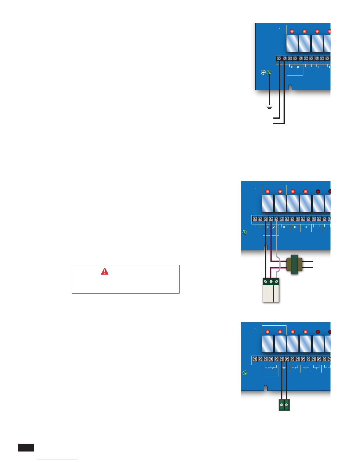
• If possible, provide a dedicated circuit breaker for the MPC Platinum. DO NOT connect
the MPC Platinum to a circuit breaker connected to high inductance devices such as
relays, pumps, fans, or motors.
• Bring the 120VAC 60Hz power wires through a bottom knockout (KO) of the enclosure.
• Class 1 voltages must enter the enclosure through a different knockout from any Class 2
voltage wiring.
• Connect the hot line to terminal marked LINE.
• Connect the neutral line to the terminal marked NEUT. DO NOT share neutrals. The
neutral line MUST come directly from the circuit breaker.
• Connect the green ground screw to earth ground. DO NOT use the neutral line as a
ground.
• Heat-Timer recommends the installation of a Surge Suppressor and a Power Switch
before the Power Line connection for safety and ease of service.
OUTPUT WIRING
• All of the MPC Platinum's outputs DO NOT SOURCE any power. If power is needed at
a specic output, a separate power source must be wired in series with the output.
• Each of the output relays can switch a 6A resistive at 120VAC load or a 1A inductive
load.
SAFETY
GROUND
MUST BE
CONNECTED
MADE IN U.S.A.
Earth
Ground
120 VAC
OUTPUT RATINGS:
120VAC, 6A RESISTIVE
1A PILOT DUTY
15A TOTAL
FOR ALL CIRCUITS
INPUT RATINGS:
115VAC 60Hz
30VA MAX
USE COPPER WIRE,
CLASS 1 WIRE ONLY
L
N
2 3 4 5
B R W
LINE
MOTORIZED
NEUTRAL
OUTPUT SYS
6 7 8 9 10 11
BURNER
VALVE
SYSTEM
WIRING TO A MOTORIZED VALVE
• The MPC Platinum is capable of operating a boiler, a oating motorized valve, or both.
• The MPC Platinum output terminal R (5) is the Common. Wire it to the 24 VAC power
source (transformer).
• Connect the transformer's second wire to the actuator Common terminal.
• The MPC Platinum output terminal B (4) is the Normally Open (N.O.). Wire it to the
actuator Open terminal.
• The MPC Platinum output terminal W (6) is the Normally Closed (N.O.). Wire it to the
actuator Close terminal.
• The N.O. and N.C. contacts are dry contacts only. They do not source any power. The
transformer is the actuator power source.
WIRING TO A BOILER
• The MPC Platinum s designed to operate a boiler, a oating motorized valve, or both.
• The BURNER output terminals are 7 and 8. They do not source any power. Wire the
burner output in series with the boiler limit circuit.
outages activates the Output and System.
WARNING
Switching to BYPASS during power
99RA
99RA
OUTPUT SYS
2 3 4 5
B R W
LINE
MOTORIZED
VALVE
NEUTRAL
Common
Open
Floating
Valve Actuator
OUTPUT SYS
2 3 4 5
B R W
LINE
MOTORIZED
VALVE
NEUTRAL
OPTION
AUX
1
CLOCK
6 7 8 9 10 11 12 13 14 15
BURNER
SYSTEM AUX
CLOCK
OPTION
1
120 VAC
24 VAC
Transformer
Close
OPTION
AUX
1
CLOCK
6 7 8 9 10 11 12 13 14 15
BURNER
SYSTEM AUX
CLOCK
OPTION
1
HT# 059085-00 F
10
Boiler
MPC Platinum Installation and Operation Manual
WIRING TO SYSTEM OUTPUT
MPC
Platinum
PREV.
(DEL)
OUT
TEMP
AUX
INPUT 0
AUX
TEMP 0
AUX
TEMP 1
DAY
HELP NEXT
PRESS TO
SELECT
BACK
MON 12/01/2010 10:01Am
ADJUST
A1
A2
A3
A4
A5
A6
A7
A8
A9
A10
A11
A12
AUX
TEMP 2
DO NOTAPPLY ANY VOLTAGE
TO SENSOR TERMINALS
A13
A14
A15
A16
A17
A18
NETWORK
PROVE
SHUTDOWN
SYSTEM
TEMP
BYPASS
ALL SENSORS MUST BE
GOLD SERIES SENSORS
INPUTS
ROUTE SENSOR AND AUXILIARY WIRES
THROUGH THIS KNOCKOUT ONLY
T
T
T
Cycle On 13/15
Cutoff = 55
o
F Day
OD = 31
o
F SYS = 138oF
AUTO
T
T
R
OPTION
OPTION
OPTION
AUX
MPC
Platinum
PREV.
(DEL)
OUT
TEMP
AUX
INPUT 0
AUX
TEMP 0
AUX
TEMP 1
DAY
HELP NEXT
PRESS TO
SELECT
BACK
MON 12/01/2010 10:01Am
ADJUST
A1
A2
A3
A4
A5
A6
A7
A8
A9
A10
A11
A12
AUX
TEMP 2
DO NOTAPPLY ANY VOLTAGE
TO SENSOR TERMINALS
A13
A14
A15
A16
A17
A18
NETWORK
PROVE
SHUTDOWN
SYSTEM
TEMP
ALL SENSORS MUST BE
GOLD SERIES SENSORS
INPUTS
ROUTE SENSOR AND AUXILIARY WIRES
THROUGH THIS KNOCKOUT ONLY
T
T
T
Cycle On 13/15
Cutoff = 55
o
F Day
OD = 31
o
F SYS = 138oF
T
T
R
MPC
Platinum
PREV.
(DEL)
OUT
TEMP
AUX
INPUT 0
AUX
TEMP 0
AUX
TEMP 1
DAY
PRESS TO
SELECT
BACK
MON 12/01/2010 10:01Am
ADJUST
A1
A2
A3
A4
A5
A6
A7
A8
A9
A10
A11
A12
AUX
TEMP 2
DO NOTAPPLY ANY VOLTAGE
TO SENSOR TERMINALS
A13
A14
A15
A16
A17
A18
NETWORK
PROVE
SHUTDOWN
SYSTEM
TEMP
ALL SENSORS MUST BE
GOLD SERIES SENSORS
INPUTS
T
T
T
Cycle On 13/15
Cutoff = 55
o
F Day
OD = 31
o
F SYS = 138oF
T
T
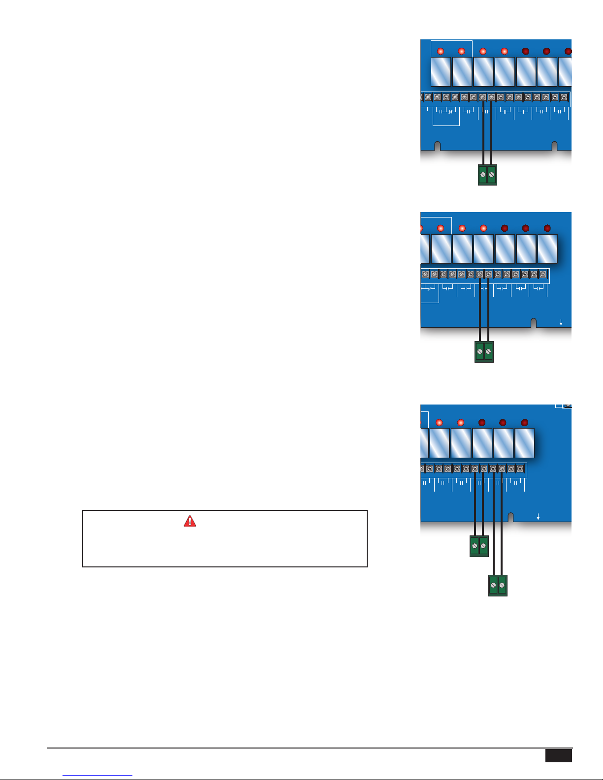
• The MPC Platinum is equipped with a System output to operate additional equipment.
The most common use for this output is operating a combustion air-damper.
• The SYSTEM output terminals are 9 and 10. These terminals do not source any power.
Wire these terminals directly to the combustion air-damper activation terminals.
• The contacts can switch a 6A resistive at 120VAC load.
• A good practice is to use the MPC Platinum's Prove input terminals to connect to the
combustion air-damper End Switch. This prevents the MPC Platinum from activating
the boiler before fully opening the damper. See "Wiring The Prove" on page 12.
• The System relay energizes whenever the Output relay energizes. When the Output relay
de-energizes, the System relay remains energized for the System Run-On period before
de-energizing.
WIRING TO AUXILIARY CLOCK
• The MPC Platinum is equipped with an AUX CLOCK output (terminals 11 and 12). Use
the output to operate additional equipment based on the Aux Schedule. A common use is
to turn on and off a set of lights based on a schedule. See "Aux Relay Schedule" on page
30.
• The AUX CLOCK output terminals do not source any power. Wire the AUX CLOCK
terminals directly to the equipment activation terminals if the equipment does not require
any power.
• If the equipment controlled require powering, make sure that its power consumption does
not exceed the output relay rating. Otherwise, use an isolation relay.
OUTPUT SYS
6 7 8 9 10 11 12 13 14 15 16 17
3 4 5
B R W
BURNER
MOTORIZED
VALVE
NEUTRAL
CLOCK
SYSTEM AUX
CLOCK
Combustion
Air Damper
OPTION
OUTPUT SYS
6 7 8 9 10 11 12 13 14 15 16 17
5
R W
BURNER
CLOCK
SYSTEM AUX
AUX
OPTION1OPTION2OPTION
CLOCK
1
OPTION1OPTION2OPTION
OPTION
2
1
OPTION
18
3
3
2
18
3
3
WIRING TO OPTION OUTPUTS
• The MPC Platinum is equipped with three optional relay outputs (OPTION1 terminals 13
and 14, OPTION2 terminals 15 and 16, and OPTION3 terminals 17 and 18). Use these
outputs to operate additional equipment based on the control logic. Each of the Option
output relays has different logic operating choices. Select the desired choice from the
Startup Menu. See "Option Outputs Modes" on page 21.
• If the control is an Internet capable control, the OPTION3 output relay will function as a
relay to manage a cable or DSL modem's power.
• The OPTION output terminals do not source any power. Wire the OPTION terminals
directly to the equipment activation terminals if the equipment does not require any
power.
• If the equipment controlled require powering, make sure that its power consumption does
not exceed the output relay rating. Otherwise, use an isolation relay. In this case, use the
OPTION terminal to break the hot power wire. going to the equipment. Then, connect
the neutral wire directly the equipment second terminal.
On Internet capable controls, you MUST use Option 3 output to
manage the power to Cable and DSL modems. However, DO NOT
use Option 3 Output to manage the power to Cellular Modems.
WARNING
Auxilary
Schedule
Activated
Device
SYS
CLOCK
8 9 10 11 12 13 14 15 16 17
SYSTEM AUX
CLOCK
2
1
OPTION1OPTION2OPTION
OPTION
OPTION
AUX
Option1
Option2
OPTION
3
18
3
ROUTE SENSOR AND AUXILIARY WIRES
THROUGH THIS KNOCKOUT ONLY
MPC Platinum Installation and Operation Manual
HT# 059085-00 F
11
INPUT WIRING
AUX
A1
A2
A3
A4
A5
A6
A7
A8
A9
NETWORK
PROVE
SHUTDOWN
SYSTEM
TEMP
T
A1
SYSTEM
TEMP
T
Shutdown
A1
A2
A3
SHUTDOWN
SYSTEM
TEMP
T
OUT
TEMP
AUX
INPUT 0
A1
A2
A3
A4
A5
A6
A7
A8
A9
A10
A11
A12
NETWORK
PROVE
SHUTDOWN
SYSTEM
TEMP
T
T
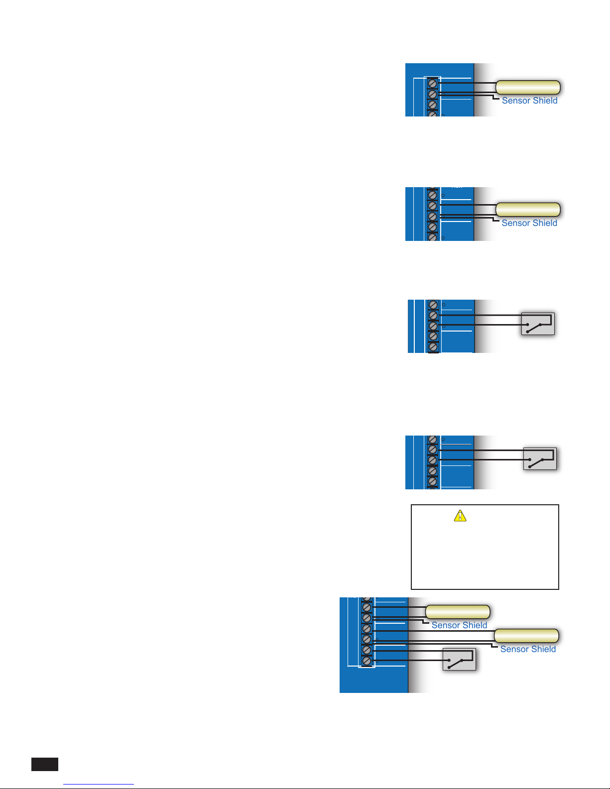
WIRING SYSTEM SENSOR
• Only use the Heat-Timer Outdoor sensor included with the MPC Platinum (#904250-00).
• You can extend the sensor wires up to 500’ by splicing it with 18 gauge shielded wire
(Belden #8760 or equivalent).
• DO NOT run sensor wire in conduit or trough with line voltage.
• Heat-Timer temperature sensors have no polarity. Connect the sensor wires to the MPC
Platinum terminals marked SYSTEM TEMP (terminals A1 and A2).
• Connect the shield to the circled terminal SYSTEM TEMP-A2 with one of the sensor
wires and cut shield off at sensor end.
T
A1
A2
A3
SYSTEM
TEMP
SHUTDOWN
System Sensor
Sensor Shield
WIRING THE OUTDOOR SENSOR
• You can extend the sensor wires up to 500’ by splicing it with 18 gauge shielded wire
(Belden #8760 or equivalent).
• DO NOT run sensor wire in conduit or trough with line voltage.
• Heat-Timer temperature sensors have no polarity. Connect the sensor wires to the MPC
Platinum terminals marked OUT TEMP (terminals A11 and A12).
• Connect the shield to the circled terminal OUT TEMP-A12 with one of the sensor wires
and cut shield off at sensor end.
WIRING THE SHUTDOWN
• You can use this feature whenever it is desirable to deactivate the MPC Platinum from a
remote location or another controller like a Building Management System (BMS).
• The Shutdown feature de-energizes the BURNER and MOTORIZED VALVE output
relays, turning off the boiler or closing the motorized valve. However, the SYSTEM relay
will remain energized for the period of the System Run-On. See "System Run-On" on
page 28.
• The Shutdown signal must be a dry contact only. DO NOT place voltage across the
SHUTDOWN terminals.
• Bring the two wires from the dry contact to the terminals marked SHUTDOWN- A3, A4.
WIRING THE PROVE
• The MPC Platinum uses the Prove input to check system operation before activating the
outputs. A good practice is to use the MPC Platinum's Prove input terminals to connect
to the combustion air-damper End Switch. This prevents the MPC Platinum from
activating the boiler before fully opening the damper. See "Installation" on page 8.
• If the PROVE input terminals are open, the MPC Platinum will enable only the System
relay. The Burner and Motorized valve (OUTPUT) relays will be de-energized when the
PROVE input is open.
• The Prove signal must be a dry contact only. No voltage can be placed across the
PROVE terminals.
• Bring the two wires from the dry contact to the terminals marked A5 and A6.
NETWORK AND AUX TEMP
• The only way to congure all Network sensors and
switches is through the Internet using the ICMS web site
(http://www.htcontrols.com).
• Heat-Timer offers a large variety of network sensors. Visit
our web site (http://www.heat-timer.com) for a list of available
Network Sensors.
• The Aux Temp inputs are capable of accepting a temperature or
a switch sensor. The user can access their values by pressing
the BACK button while in the default screen.
HT# 059085-00 F
12
MPC Platinum Installation and Operation Manual
A10
A11
A12
A13
A14
A2
A3
A4
A5
A6
A4
A5
A6
A7
A8
INPUT 0
T
OUT
TEMP
T
AUX
TEMP 0
SHUTDOWN
PROVE
PROVE
NETWORK
Outdoor Sensor
Sensor Shield
Shutdown
Prove
ALERT
The PROVE input terminals must
be shorted for MPC Platinum to
provide heat. DO NOT remove the
factory installed PROVE jumper
unless replacing it with a Prove
signal.
A13
T
AUX
T
T
TEMP 0
AUX
TEMP 1
AUX
TEMP 2
A14
A15
A16
A17
A18
Temp. Sensor
Sensor Shield
Space Sensor
Sensor Shield
Switch Input

TESTING THE SENSORS
A1
A2
A3
A4
A5
A6
A7
A8
NETWORK
PROVE
SHUTDOWN
SYSTEM
TEMP
T
External Boiler Call
• On a power up, the Platinum control goes through a countdown followed by the default screen.
• The default screen displays
Sensor temperature.
• If either of the two temperatures reads
• You can only view Network sensor readings on the Internet.
(SYS) to show the Heating System Sensor (HSS) temperature and (OD) to show the Outdoor
OPEN, SHORT, or an incorrect temperature. See "Troubleshooting" on page 44.
AUX INPUT
• If the boiler is activated by another control, i.e. domestic hot water aquastat, the Aux
Input will allow a Heat-Timer communication package to chart a time line for boiler
status.
WIRING NETWORK SENSORS
(Requires Internet Communication Package Upgrade)
•
the ICMS website (http://www.htcontrols.com).
• The MPC Platinum Network terminals can connect up to 64 or 128 network sensors,
depending on the control hardware.
• Use the Mini-MIG to handle up to 16 temperature, switch, or count sensors. Multiple
Mini-MIG’s can connect to an MPC Platinum.
• A variety of network sensors is available for the MPC Platinum:
◦ Stack Sensor (measures the stack temperature),
◦ Water Meter Count/Pulse sensor (measures water consumption),
◦ Oil Tank Monitor (measure the amount of oil in a tank),
◦ Pressure, vacuum, and humidity transducers,
◦ Multiple Input Gateway (Mini-MIG) that gives the capability of connecting the
control to multiple temperature or switch sensors and a single count sensors.
◦ Conductivity sensors (to measure boiler chemical requirement).
CONNECTING WIRELESS SENSOR SYSTEM
(Requires Internet Communication Package Upgrade)
•
Internet (http://www.htcontrols.com).
• The MPC Platinum can connect to up to 64 or 128 network
sensors, depending on the control hardware. These numbers
include wireless sensors, wireless Transceivers, and the
wireless Network Manager.
• Use Wireless Transceivers to extend the range of the wireless
network and reduce building sensor wiring.
• The wireless Network Manager connects directly to the
communication board's RS485.
• The balance of the wireless system communicates its
information to the wireless Network Manager.
Send Packet
Button
NM RS485
Cable (Provided)
RS485
Connect to
Wireless NM
Wireless Network Manager
1 2 3 4
ON
A9
A10
A11
A12
T
AUX
INPUT 0
OUT
TEMP
Network
Sensors
Platinum
PWR
Network
L N
N1
1 2
3 4
Platinum Control
A(+)
G
B(-)
A(+)
G
B(-)
External Boiler Call
RS485
T
OUT
TEMP
SHUTDOWN
S+S
PRESS
4-20 mA
Network
NETWORK
PROVE
A10
T
AUX
TEMP 0
A12
A13
T
AUX
TEMP 1
A14
A15
T
AUX
TEMP 2
A16
A17
A18
MIG
Mini-MIG
Multiple Input Gateway
Power
Comm
T1 T2 T3 T4
125 72 73 75
VIEW
RESET
6
Input 719Input 821Input
20 22
Input 923Input 1025Input 1127Input 12
29
24 26 28 30 32 34 36 38
Pulse
Input 13
14
Input 15
Input
Input 16
31 33
35
37
Input 5
Input 29Input 311Input 4
Input 1
7
13
15 17
10 12 14 16 18
8
CPU Board
Wireless
Wireless
Network
Manager
0056789
Water
Meter
Stack
Sensor
Sensor
Oil Level
MPC Platinum Installation and Operation Manual
Motherboard
HT# 059085-00 F
13
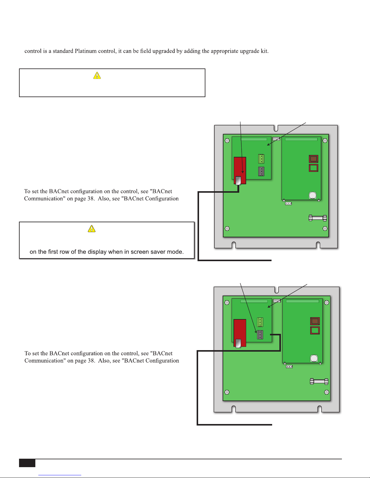
REMOTE COMMUNICATION WIRING
PLATINUM PANEL CONNECTED
TO BACnet IP Network
Ethernet socket
PLATINUM PANEL CONNECTED
TO BACnet MS/TP Network
• All standard Platinum controls come with a Motherboard and a CPU board.
• If the Platinum control part number ends with RINET, BAC, or BUS; then it also comes with a communication board. If a
A new CPU board and the
respective communication board will be included in any of the Upgrade Kits.
ALERT
Always bring your communication cable through one of the side
knockouts. DO NOT use the bottom knockouts for communication cabling.
BACNET WIRING
BACNET IP WIRING
• The Ethernet cable should use the Platinum control's enclosure closest
side knockout.
•
Connect the CAT-5E BACnet IP cable to the
socket on the back of the control's Communication Board.
• For reliable communication, do not run CAT-5E cables more than
150 Ft. CAT-6 cables can have a maximum run of 300 Ft.
•
Manual".
ALERT
A BACnet capable Platinum control displays
-- NETWORK PANEL --
BACNET MS/TP WIRING
• The RS485 cable should use the Platinum control's enclosure closest
side knockout.
• Connect the BACnet MS/TP cable to the RS485 connector
communication socket on the back of the control's Communication
Board. The Communication Board terminals are labeled 'A (+)', G
(Ground), and 'B (-)'.
• Use 18# AWG Twisted Pair cable. The cable length must not exceed
3500 feet.
• The ground RS485 terminal (G) MUST be connected to the BMS
RS485 Ground.
•
RS45 communication
connect to Cat-5 cable
Motherboard
CAT5/Ethernet Cable
Black RS485 socket
connect to BACnet MS/TP
Communication Board
A(+)
G
B(-)
A(+)
G
A(+)
G
B(-)
A(+)
G
B(-)
B(-)
CPU Board
Connect to Ethernet
Connection on BACnet Network
Communication Board
CPU Board
Manual".
HT# 059085-00 F
14
Motherboard
RS485 Cable
Connect to BACnet MS/TP Network
MPC Platinum Installation and Operation Manual
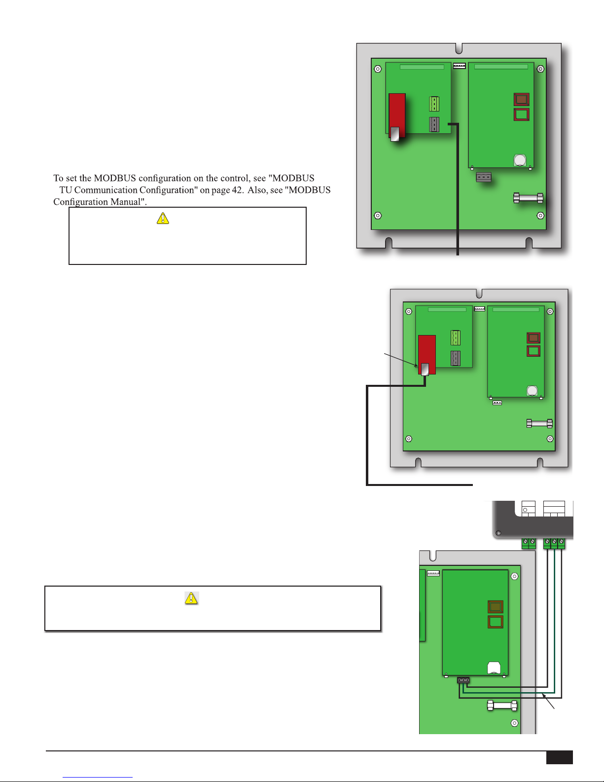
MODBUS RTU WIRING
TO MODBUS NETWORK
PLATINUM PANEL CONNECTED
TO THE INTERNET
DHW Energy Saver
DHW Energy Saver
COM
3 4 5
A GND B
16VAC
1 2
~ ~
• A MODBUS communication board and a CPU board with the
MODBUS software is required for proper MODBUS communication.
• Heat-Timer Platinum control MODBUS communication uses a
RS485 connection.
• Connect the MODBUS RS485 cable to the Communication Board's
RS485 socket. The Communication Board's RS485 socket has ‘A
(+)’, G (Ground), and ‘B (-)’ terminals. Polarity is observed,
• The cable length must not exceed 3500 feet.
• Must Connect the ground RS485 terminal (G) to the BMS RS485
Ground.
•
R
ALERT
DO NOT USE the RS485 Connector on the Motherboard
for MODBUS communication. Use the RS485 Connector
on the MODBUS Communication Board instead.
INTERNET WIRING
MODBUS
Communication
Board
Motherboard
Connect Black RS485
to MODBUS Network
A(+)
G
B(-)
A(+)
G
B(-)
CPU Board
ETHERNET CONNECTION TO MODEM
• Connect the Ethernet cable (provided) to the modem socket marked
Ethernet/LAN. Class 2 voltage wires must use a different knockout
from Class 1 voltage wires.
Ethernet socket
connect to
Cat-5 cable
• Connect the other Ethernet cable end to the Communication board,
through the side knockout.
ETHERNET CONNECTION TO PLATINUM
CONTROL
• Bring the Ethernet line through one of the Platinum Enclosure side
knockouts. Class 2 voltage wires must use a different knockout from
Class 1 voltage wires.
• Connect the Ethernet cable to the Communication Board on the back
of the Platinum control. See "Platinum Internet Setup Manual".
DHW ENERGY SAVER WIRING
• The DHW Energy Saver communicates all of its information to the Platinum control
using RS485 (3-wire connection).
• The DHW Energy Saver RS485 terminals are wired to the Platinum main board’s
RS485 (under the PCB board).
• Follow the wiring as per the graph on the right.
ALERT
DO NOT connect the DHW Energy Saver to the RS485 on the Platinum RI board.
Instead, connect the DHW Energy Saver RS485 to the Platinum main board.
• Maximum wiring length should not exceed 100 Feet. Use 18 gauge 2-conductor
shielded wire (#18). Connect the shield to the middle terminals on both of the RS485
connections. To eliminate communication errors, DO NOT splice the communication
cable wires.
• When connecting the DHW Energy Saver and a Platinum Extension to the same
connector, make sure to splice the cables externally before bringing them to the RS485
Plug Connector on the main Platinum Board. See "DHW Energy Saver Manual".
Communication
Motherboard
CAT5/Ethernet Cable
Platinum main board
Board
A(+)
G
B(-)
A(+)
G
B(-)
PCB board
Use RS485
Communication
on the back of the
CPU Board
Connect to Internet
16VAC
~ ~
1 2
COM
A GND B
3 4 5
Shield
MPC Platinum Installation and Operation Manual
HT# 059085-00 F
15
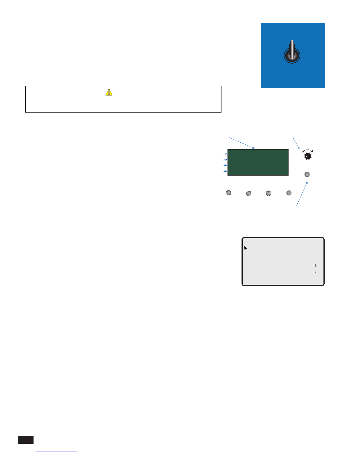
AUTO/BYPASS SWITCH
MPC
Platinum
PREV.
DAY
HELP NEXT
MON 12/01/2010 10:01Am
Cycle On 13/15
Cutoff = 55
o
F Day
OD = 31
o
F SYS = 138oF
R
• The switch must be in the AUTO position for the MPC Platinum to control the heating
system.
• The BYPASS position overrides all automatic control of the MPC Platinum.
• If the MPC Platinum has power and is operational, switching to BYPASS automatically
activates the Motorized Valve, the Burner, and the System output.
• Switching the control to BYPASS manually during a power outage, activates the
Motorized Valve, Burner , and System outputs.
ALERT
Switching the MPC Platinum into Bypass overrides all automatic operation. In
Bypass, the boiler will run constantly on its own limits or the valve will be fully open.
AUTO
BYPASS
SETTING THE CONTROL
Digital display shows the date, heating
status, and cutoff, outdoor, and system
values. To view and adjust settings,
press the Adjust/Select button.
DISPLAY AND CHANGING SETTINGS
The MPC Platinum comes with an 80 character (20 character per row x 4
rows) digital display with simple English menus.
ADJUST/SELECT This knob turns to ADJUST and when pressed
it SELECTs. Turn the knob to scroll through
settings. Press a menu option to accept a setting,
BACK Use to go back to the previous menu,
NEXT In Schedules, goes to next schedule period,
DAY In Schedules, advances through weekdays,
PREV.(DEL) Clears a specic schedule setting.
HELP Provides help instructions regarding the current
menu function.
Date and Time
Messages
Cutoff and Schedule
Sensor Status
MENU TYPES
When powering up the MPC Platinum for the rst time, it will take you through an 70
second count down followed by the System Startup Settings then another 10 second boot
setup and nally end with the default screen. Once the control is mounted and wired, set
up an initial pilot program.
• Set and adjust System Startup Settings: The contractor sets these values after installing
the control for the rst time. End users should avoid changing these settings as they
will change the control operating logic. If the Startup Settings are not correct, the MPC
Platinum may operate the system incorrectly.
• Set and adjust System Settings: These settings adjust the system to the specic building
characteristics. These are general settings that control the amount of heat provided. The
default settings will generally work in most applications, but adjustments should ne-
tune the performance of your system.
• Set and adjust Maintenance: Provide calibration tools for the sensors and allow a
password to be set.
• Set and adjust Schedules: Sets the Day/Night heat schedule and the Aux clock schedule.
Four pairs of Day/Night times can be set for each day of the week. In addition, the Aux
relay is capable of following the Aux Schedule. It is programmable to turn on or off up
to eight times per day.
• Shift: Allows you to temporarily shift from Day (higher heat level) to Night (lower
heat level) settings, or vice versa, without reprogramming the times of the Day/Night
Schedule.
Depress the knob to move
forward through the menus and to
accept changes. To change a
setting's value, rotate the knob.
MON 12/01/2010 10:01Am
Cycle On 13/15
Cutoff = 55
OD = 31
o
F Day
o
F SYS = 138oF
PREV.
(DEL)
- SYSTEM SETTINGS Season Winter
Day Heat Adjust E
Night Heat Adjust B
Day Cutoff 55
Night Cutoff 40
<More Settings>
DAYHELP NEXT
Depress the button to go back
through the menus, or to view a
setting value without changing it
ADJUST
PRESS TO
SELECT
BACK
F
F
HT# 059085-00 F
16
MPC Platinum Installation and Operation Manual

DISPLAY MESSAGES
The MPC Platinum normal display layout utilizes the second line for message indications. The following is a list of the most
common Message Display Line information:
• BYPASS: 0D 0H 15M The control is switched to Bypass for the amount of time indicated. See "AUTO/BYPASS Switch"
on page 16.
• Cycle On: 1/5 min The MPC Platinum is in the Cycle-ON period for a minute out of a total Cycle-ON of 5 minutes.
See "Troubleshooting" on page 44.
• Cycle Off: 6/60 min The MPC Platinum is in the Cycle-OFF period. Only 6 Cycle-ON minutes out of the Cycle 60
minutes has elapsed. See "Understanding the Cycle Concept" on page 4.
• Est Heat at: 125°F The MPC Platinum is energizing Output relay to establish heat before starting a heating cycle. See
"Understanding the Cycle Concept" on page 4.
• Fast C/D: 68°F The Boost option selected is Vari+ESD. The MPC Platinum turns the output off before the last
Night Schedule setting for the Fast Cool Down until the space average temperature drops below
68°F (Night Space Target). See "Early Shutdown Curves" on page 27.
• Manual Boost 25/30 min The MPC Platinum has started a Manual Boost in a Cycle Operation Mode. 25 minutes have
elapsed of the 30 Manual Boost minutes. See "Boost Mode" on page 26.
• Prove Failure The Prove input terminals are now open. The boiler relays are de-energized. However, the System
relay will remain energized. See "Wiring The Prove" on page 12.
• Sensor Fault Either the Outdoor or the System sensor is reading Short or Open. The Output relay will be
energized or de-energized based on the Sensor Fault setting. See "Sensor Fault" on page 20.
• Shutdown Active The SHUTDOWN input is Shorted. Outputs are not active. See "Wiring the Shutdown" on page 12.
• Space L/O: 71°F In Cycle Operation Mode the MPC Platinum is in Space Lockout (utilizing space sensors) until the
space average drops below 71°F. See "Space Lockout" on page 28.
• Steam Time 12/15 min District Steam is the Operating Mode choice. The control activated the output relay for 12 out of 15
minutes before starting the cycle. See "Operation Mode" on page 20.
• Summer The control is set to Summer. No heat is active. See "Season" on page 23.
• Thermal Lockout: 125°F In Cycle Operation Mode the MPC Platinum is in Thermal Lockout until the System Sensor
Temperature drops below the System Set Point less the Differential. See "Thermal Lockout" on
page 28.
• Vari Boost Active The MPC Platinum has started a Vari Boost in a Cycle Operation Mode. See "Boost Mode" on
page 26.
• Waiting for Prove There is a call for heat and the Prove terminals are open before the boilers start ring. The boiler
relay is de-energize while the System relay is energized. See "Wiring The Prove" on page 12.
The third line is reserved for the Cutoff and any day or night setting messages. The following is a list of the most common third
line Messages:
• Day Ext The control is shifted to the Extended Day schedule for specied amount of time. See "Shift" on
page 33.
• Day Shf The control is shifted to the Day schedule from the Night Schedule. See "Shift" on page 33.
• Night ESD The Night Early-Shutdown is active. See "Early Shutdown Curves" on page 27.
• Night Shf The control has been shifted to the Night schedule from the Day Schedule. See "Shift" on page 33.
• No Call for Heat The outdoor temperature is above the Outdoor Cutoff. See "Day and Night Outdoor Cutoff" on
page 24.
• Sys RunOn: 2/5 min The Output relay has turned off and the System relay has been running for 2 minute and will need
to run for a total of 5 minutes. See "System Run-On" on page 28.
MPC Platinum Installation and Operation Manual
HT# 059085-00 F
17

MENU SETTINGS
------ SETTINGS ----- Season Summer
Shift
<System Settings>
<Schedules>
<Maintenance>
<System Startup>
SYSTEM STARTUP pg 20
- SYSTEM STARTUPSELECT
To continue
- ARE YOU SURE? -
NO
YES
--- SENSOR TYPE -- F
C
-- OPERATION MODE --
Burner or Valve
District Steam
--- SHUTDOWN/TSTAT ---
Shutdown/Disable
Tstat/Enable
--- CYCLE LENGTH ---
60 Min
[
--- SENSOR FAULT -- Output On
Output Off
- DAY LIGHT SAVING
Enable
Disable
SHIFT pg 33
SHIFT FROM NIGHT TO
Day
SHIFT FROM DAY TO
Night
Extend Day
Schedule
Night
Extend Day Sched
Day
Schedule
- EXTEND DAY TIME-
90 Min
[
]
SCHEDULES pg 29
----- SCHEDULES ---- Day/Night Schedule
Copy Schedule
Set Date/Time
Aux Schedule
------ SCHEDULES -----Copy Mon Schedules
To All Other Days
(Select to Execute)
MAINTENANCE pg 31
- MAINTENANCE MENU System Trim +0 F
Outdoor Trim +0
Fast Cycle Off
Password
<DHW Settings>
F
------ SCHEDULES -----MON # 1
Day Time 6:00Am
Night Time 10:00Pm
Press DAY
------ SCHEDULES -----TUE # 1
Day Time 6:00Am
Night Time 10:00Pm
Press NEXT
------ SCHEDULES -----TUE # 2
Day Time **:**
Night Time **:**
---- SYSTEM TRIM ----
F
+0
[
]
DHW pg 32
]
--- DHW SETTINGS -- <Supply Settings>
<Return Settings>
Demand Schedule
Copy Schedule
DHW SUPPLY SETTINGS
Use Sensor? No
Setpoint 140
Peak Diff 10
Light Diff 20
F
F
F
- FAST CYCLE TEST Off
On
PASSWORDS ENABLED?
No
Yes
--------- LOGIN ---------
Enter Password:
****
OPTION RELAY 1 MODE
Off
Inverse of Aux
Day
Below Outdoor Cut
OPTION RELAY 2 MODE
Off
Inverse of Output
Heat Established
Summer
HT# 059085-00 F
18
DHW RETURN SETTINGS
Use Sensor? No
Setpoint 120
Peak Diff 10
Light Diff 20
DHW SUPPLY DEFAULT
Off
On
MPC Platinum Installation and Operation Manual
CHANGE PASSWORD?
No
F
F
F
Yes
--- SET YEAR --2000
[
DHW RETURN DEFAULT
Off
On
]

------ SETTINGS ----- Season Summer
Shift
<System Settings>
<Schedules>
<Maintenance>
<System Startup>
SEASON pg 23
-- DAY ADJUSTMENT -Higher = More heat
E
[
-------- SEASON ------ Winter
Summer
-- SYSTEM SETPOINT --
F
]
[
140
]
SETTINGS pg 23
- SYSTEM SETTINGS Season Winter
Day Heat Adjust E
Night Heat Adjust B
Day Cutoff 55
Night Cutoff 40
<More Settings>
--- SYSTEM RUN-ON --2 min
[
- THERMAL LOCKOUT On
Off
- BACNET SETTINGS BACnet ID 5
IP___,___,___,___
Msk___,___,___,___
Gwy___,___,___,___
Switch to MS/TP
----- DAY CUTOFF ----F
55
[
F
F
SYSTEM SETTINGS 2
Sys Setpoint 140 F
Sys Diff 25
Dis Stm Dly 15min
]
BACnet
Boost Mode Vari
Sys Run-On 2 Min
Thermal Lockout On
<Remote Interface>
]
F
REMOTE INTERFACE
pg 34
SYSTEM SENSOR DIFF
F
25
[
DISTRICT STEAM DELAY
15min
[
]
]
BOOST pg 26
--- BOOST MODE-- Disabled
Manual
Vari
Vari+ESD
- BOOST ADJUSTMENT Higher = More Boost
3.0
[
- BOOST ADJUSTMENT Higher = More Boost
0min
[
]
]
- BACNET SETTINGS BACnet ID 5
MS/TP Address 1
Baud 9600
Switch to IP
INTERNET SETTINGS
IP___,___,___,___
Msk___,___,___,___
Gwy___,___,___,___
DNS___,___,___,___
MODBUS SETTINGS
MAC Address
Baud 9600
MPC Platinum Installation and Operation Manual
Internet
MODBUS
REMOTE INTERFACE
<Network Settings>
SpaceLockout Disable
Day Target 75
Night Target 65
- SPACE LOCKOUT -
Disable
F
F
Enable
- DAY SPACE TARGET F
75
[
NIGHT SPACE TARGET
F
65
[
]
]
HT# 059085-00 F
19

STARTUP SETTINGS
Enter menu by pressing SELECT: Settings/System Startup
If entering this menu option after the control has been set, several warnings will display before
continuing. After accepting all the warnings, the following Startup option menus must be set:
• Sensor Type (°F for Fahrenheit or °C for Celsius.)
• Operation Mode (Burner/Valve or District Steam)
• Cycle Length
• Sensor Fault (Output On or Output Off)
• Daylight Savings (Enable or Disable)
• Option relays' modes
ALERT
All Startup settings cannot
be changed on the Internet
except for Sensor Fault
SENSOR TYPE
°F Fahrenheit or °C for Celsius Default: °F Fahrenheit
SELECT Settings/System Startup/.../Sensor Type
• This option allows you to change the sensors' display and all temperature settings between
Fahrenheit and celsius.
OPERATION MODE
Burner/Valve or District Steam Default: Burner/Valve
SELECT Settings/System Startup/.../ Sensor Type / Operation Mode
• In most buildings, the time required for the heating system to ll with steam depends on
several factors. For example, using direct burner operation, the time it takes to generate
steam depends on the boiler off time length. With a valve, the amount of time also depends
on the status of the heating plant and may additionally vary depending on the balance of the
heating zones' valve position.
• However, in cases where steam is distributed from a local power authority (district steam) or
other sources where the steam is always available at a constant pressure, the time required
to ll the heating system with steam will be relatively constant.
• If your steam source is of the later type, you may decide to select the District Steam option.
• With the District Steam option, the HSS is not used. The MPC Platinum uses a timer to
start the Cycle-ON. See "District Steam Delay" on page 25.
• Selecting the District Steam option may result in overheating and unnecessary energy
expenses as the Thermal Lockout feature will not be available.
CYCLE LENGTH
Adjustable from 10 to 240 minutes Default: 60 minutes
SELECT Settings/System Startup/.../ Sensor Type / Operation Mode / Cycle Length
• The Cycle Length is directly related to the type of radiation used. The following is Heat_
Timer recommended Cycle Length:
○ For most cast iron radiation, choose a 60-minute cycle. If the radiators are very large or
the system is oversized, choose a 90-minute cycle.
○ For convector or baseboard radiation, choose a 30-minute cycle.
○ For air handlers or blower units, choose a 20-minute cycle.
--- SENSOR TYPE -- F
C
-- OPERATION MODE - Burner or Valve
District Steam
--- CYCLE LENGTH ---
60 Min
[
]
SENSOR FAULT
Output On or Output Off Default: Output On
SELECT Settings/System Startup/.../Sensor Fault
• In cases where the Outdoor sensor reads SHORT or OPEN, you can select whether you
want to default to providing continuous heat, or no heat at all.
• To help prevent a freeze-up in such a circumstance, the user can select Output On which
turns on the output relay energizing the boiler or maintain the valve open, thereby providing
continuous heat until the sensor problem can be corrected.
• The Output Off option does not provide any heat if the sensor reads a fault value.
HT# 059085-00 F
20
MPC Platinum Installation and Operation Manual
--- SENSOR FAULT -- Output On
Output Off

DAY LIGHT SAVING MODE
Enable or Disable Default: Enable
SELECT Settings/System Startup/.../Sensor Fault/Day Light Saving
• If it is desirable for the MPC Platinum to automatically adjust the system clock for Day
Light savings, select Enable.
• If the control is located where Day Light Savings time is not observed, or if you wish to
manually change the clock for Day Light Savings, select Disable.
• For accuracy, Internet controls receive their date and time through Heat-Timer ICMS web
servers based on the time zone set for the building.
OPTION OUTPUTS MODES
OPTION RELAY 1 MODE
Off, Inverse of Aux, Day, Below Outdoor Cutoff Default: Off
SELECT Settings/System Startup/.../Day Light Saving/ Option Relay 1 Mode
• Each of the Option output relays can perform a different function based on many of the
control operating functions. These menus assign the functionality to the relays
• If the default "Off" setting is selected, Option 1 Relay will never energize.
• If the "Inverse of Aux" is selected, Option 1 Relay will energize whenever the Aux Clock
relay is de-energized and will de-energize whenever the Aux Clock relay is energized.
• If "Day" is selected, Option 1 Relay will energize whenever the MPC Platinum is holding
the Day heat setting and will de-energize when the MPC Platinum is holding the Night heat
setting.
• If "Below Outdoor Cutoff" is selected, Option 1 Relay will energize whenever the Outdoor
sensor temperature registers below the Outdoor Cutoff temperature and will de-energize
whenever the Outdoor sensor temperature registers above the Outdoor Cutoff.
- DAY LIGHT SAVING
Enable
Disable
OPTION RELAY 1 MODE
Off
Inverse of Aux
Day
Below Outdoor Cut
OPTION 2 RELAY MODE
Off, Inverse of Output, Heat Established, Summer Default: Off
SELECT Settings/System Startup/.../Option Relay 1 Mode/Option Relay 2 Mode
• Each of the Option output relays can perform a different function either based on many of
the control operating functions. These menus assign the functionality to the relays
• If the default "Off" setting is selected, Option 2 relay will never energize.
• If the "Inverse of Output" is selected, Option 2 Relay will energize whenever the Output
relays are de-energized and will de-energize whenever the Output relays are energized.
• If "Heat Established" is selected, Option 2 Relay will energize whenever the MPC Platinum
establishes heat (the temperature of the HSS is above the System Set Point) and it will de-
energize when the MPC Platinum does not have its heat established.
• If "Summer" is selected, Option 2 Relay will energize whenever the MPC Platinum is
switched to the Summer mode (no heat is provided) will de-energize whenever the MPC
Platinum is in Winter.
OPTION 3 RELAY MODE
(Available in Standard non-communication controls only)
Off, Inverse of System, Night, Above Outdoor Cutoff Default: Off
SELECT Settings/System Startup/.../Option Relay 2 Mode/Option Relay 3 Mode
• If the MPC Platinum is a communication control, Option 3 output will not be available for
programming. On Internet controls, Option 3 output relay is used to switch power to the
Internet Modem/Router. Since some cable modems may loose their communication and not
be able to restore it unless they are powered down for a short period. In this case, Option 3
incorporates a built-in delay for the modem.
• If the MPC Platinum is a Standard, non-communicating control, its Option 3 output can be
programmed to operate based on one of the four different options.
• If the default "Off" setting is selected, Option 3 relay will never energize.
• If the "Inverse of System" is selected, Option 3 Relay will energize whenever the System
relay is de-energized and will de-energize whenever the System relay is energized.
OPTION RELAY 2 MODE
Off
Inverse of Output
Heat Established
Summer
OPTION RELAY 3 MODE
Off
Inverse of System
Night
Above Outdoor Cutoff
MPC Platinum Installation and Operation Manual
HT# 059085-00 F
21

• If "Night" is selected, Option 3 Relay will energize whenever the MPC Platinum is holding
the lower, or Night, heat settings and will be de-energize when the MPC Platinum is holding
the Day settings.
• If "Above Outdoor Cutoff" is selected, Option 3 Relay will energize whenever the Outdoor
sensor temperature registers above the Outdoor Cutoff temperature and will de-energize
whenever the Outdoor sensor temperature registers below the Outdoor Cutoff.
DHW SUPPLY AND RETURN DEFAULTS
SELECT Settings/System Startup/.../Option Relay 2 Mode/DHW Supply Default
• These options set the DHW Energy Saver's (DHW-ES) Supply and Return output relays
behavior when the DHW-ES looses communication with the Platinum controlor when the
respetive sensor reads a fault condition (Short or Open).
• The DHW-ES output relay may take up to 1 minute to respond to the fault or no-
communicaiton condition.
SETTING THE DATE AND TIME
SELECT Settings/System Startup/.../Option Relay 3 Mode/Set Year/Set Month/...
• The date and time are used to maintain the controls schedules.
• Internet controls receive the date and time through the Heat-Timer servers based on the time
zone set for the building.
• The control has a coin Lithium battery (CR2032) (HT# 020002-00) that is used to maintain
the control's date and time during power outages. This battery can maintain the clock for up
to a total of 100 days. See "Activate the Battery" on page 8.
DHW SUPPLY DEFAULT
Off
On
DHW RETURN DEFAULT
Off
On
------- SET YEAR -----2000
[
------- SET MONTH ------
January
February
March
April
------- SET DAY ------
1
[
- SET PRESENT TIME -
12:** Pm
]
]
HT# 059085-00 F
22
MPC Platinum Installation and Operation Manual

OPERATION
SYSTEM SETTINGS
Enter menu by pressing SELECT: Settings/System Settings
for enhanced comfort and more fuel savings. The MPC Platinum behaves differently based on
the selected Control Mode (see Startup Settings).
- SYSTEM SETTINGS Season Winter
Day Heat Adjust E
Night Heat Adjust B
Day Cutoff 55
Night Cutoff 40
<More Settings>
F
F
Burner or Valve
• Season
• Day and Night Heat Adjustments
• Day and Night Outdoor Cutoffs
• Season (Winter or Summer)
• System Set Point
• System Differential
• Boost Mode
• Pump Run-On
• Thermal Lockout
• Space Lockout
• Day and Night Space Target
♦
♦
District Steam
• Season
• Day and Night Heat Adjustments
• Day and Night Outdoor Cutoffs
• Season (Winter or Summer)
• District Steam Delay
• Boost Mode
• Pump Run-On
• Space Lockout
• Day and Night Space Target
• Remote Interface (Can be utilized with
Remote Communication Only)
♦
♦
• Remote Interface (Can be utilized with
Remote Communication Only)
♦ Requires Internet Remote Communication
SEASON
Winter, Summer Default: Winter
SELECT Settings/Season when in Winter setting
SELECT Settings/System Settings/Season when in Summer setting
• The Season setting controls whether the MPC Platinum will give heat.
• When set to Summer, the MPC Platinum does not energize the Boiler and the Motorized
Valve outputs.
• When set to Winter, the MPC Platinum operates the building heat whenever the outdoor
temperature falls below the Cutoff temperature. See "Day and Night Outdoor Cutoff" on
page 24.
• During the heating season, the control must be set to Winter mode.
• When the heating season is over, it is a good practice to switch the control to the Summer.
SYSTEM SETTINGS 2
Sys Setpoint 140 F
Sys Diff 25
Dis Stm Dly 15min
Boost Mode Vari
Sys Run-On 2 Min
Thermal Lockout On
<Remote Interface>
REMOTE INTERFACE
<Network Settings>
SpaceLockout Disable
Day Target 75
Night Target 65
-------- SEASON ------ Winter
Summer
ALERT
Do not turn the power off to the
MPC Platinum when the heating
season is over. If you do so,
the battery will run down and
have to be replaced. Instead,
switch its Season to Summer.
F
F
F
DAY AND NIGHT HEAT ADJUSTMENT
Adjustable from A through P Default: E (Day) / B ( Night)
SELECT Settings/<System Settings>/Day Heat Adjust or Night Heat Adjust
• Heat Adjustments control the duration of Cycle-On based on the outdoor temperature.
• An "A" setting gives the least duration of Cycle-On at any given outside temperature. A "P"
setting gives the longest Cycle-On.
• The MPC Platinum has two heat levels, Day and Night. The Day heat level is for when
the building is occupied and people are active. The Night heat level holds a lower ambient
temperature, and is for when the building is unoccupied or people are sleeping. The Day
and Night Heat Adjustment are individually set.
• The length of the Cycle-ON is based on the Outdoor Cutoff temperature. Therefore, if
you set both the Day and Night Heat Adjustments to the same value, you will get less heat
at Night. For example, with both Heat Adjustments set to F and the factory set Cutoffs of
55°F for Day and 40°F for Night, when the outdoor temperature is 25°F the On part of the
cycle will last for 15 minutes in Day, and only 7 minutes at Night.
• If the building is too cold, adjust the appropriate setting up a letter (Day Heat Adjust if it
is too cold in the Day time and Night Heat Adjust if it is too cold in the Night time). For
example; from F to G. Then wait at least 24 hours before evaluating the new adjustment.
Otherwise, adjust it up another letter and wait an additional day for the results.
• Similarly, if the building is too warm, reduce the Heat Adjustment one letter and wait for 24
hours before making any additional adjustments.
MPC Platinum Installation and Operation Manual
-- DAY ADJUSTMENT -Higher = More heat
E
[
- NIGHT ADJUSTMENT Higher = More heat
B
[
]
]
23
HT# 059085-00 F

CYCLE LENGTH TABLE
Outdoor Cutoff Minus Outdoor Temperature
95°F 90°F 85°F 80°F 75°F 70°F 65°F 60°F 55°F 50°F 45°F 40°F 35°F 30°F 25°F 20°F 15°F 10°F 5°F 1°F
A 45 41 37 33 29 25 22 18 15 13 10 8 5 3 2 0 0 0 0 0
B 57 51 46 41 37 33 28 25 21 18 15 12 9 7 5 3 1 0 0 0
C C 59 54 48 43 38 33 29 25 21 18 15 12 9 7 5 3 1 0 0
D C C C 55 49 43 38 34 29 25 21 17 14 11 9 6 4 2 1 0
E C C C C 55 49 43 38 33 28 24 20 17 13 10 8 6 4 2 1
F C C C C C 55 49 43 37 32 27 23 19 15 12 9 7 5 3 2
G C C C C C C 54 48 42 36 31 26 22 18 14 11 8 6 4 3
H C C C C C C C 53 47 40 35 29 25 20 16 13 10 7 5 4
I C C C C C C C 59 52 45 39 33 27 23 18 15 11 9 6 5
J C C C C C C C C 58 50 43 37 31 25 21 16 13 10 7 6
K C C C C C C C C C 56 48 41 34 28 23 19 15 11 8 7
Heat Adjustment Setting
L C C C C C C C C C C 53 45 38 32 26 21 16 13 9 7
M C C C C C C C C C C 59 51 43 35 29 23 18 14 11 8
N C C C C C C C C C C C 56 47 39 32 26 20 16 12 9
O C C C C C C C C C C C C 53 44 36 29 23 17 13 10
P C C C C C C C C C C C C 59 49 40 32 25 19 15 12
- "C" minutes denotes continuous operation
Minutes ON (based on 60 minute cycle length)
The duration of the Cycle-ON (when the heat source is activated)
depends on the following four factors:
1. Outside temperature
2. Outdoor Cutoff temperature
Heat Adjustment: G
Outside Temp.: 30°F
Outdoor Cutoff: 55°F
3. Heat Adjustment settings
4. Cycle length
• When the outside temperature is above the Outdoor Cutoff,
the MPC Platinum will not call for heat. Below the Cutoffs,
the length of Cycle-ON is adjusted by the Heat Adjustment
Settings. '"A" gives the shortest duration of heat while "P"
gives the longest duration of heat as shown by the chart.
Outdoor Cutoff 55°F
- Outdoor Temp. 30°F
_____________________
Select Highlighted
Vertical Column 25°F
DAY AND NIGHT OUTDOOR CUTOFF
On, 20°F/-7°C to 100°F/38°C, Off Default: 55°F (13°C) Day / 40°F (4°C) Night
SELECT Settings/<System Settings>/Day Outdoor Cutoff or Night Outdoor Cutoff
• The Day and Night Outdoor Cutoffs determine when the MPC Platinum calls for heat.
• When the outside temperature rises above the Cutoff by 2F°, the MPC Platinum stops
providing steam to heat the building.
• When the temperature falls below the Cutoff, the MPC Platinum begins running cycles and
providing steam to the heating system.
• The Cutoff temperature also affects the amount of heat provided to the building. See
"Understanding the Cycle Concept" on page 4.
SYSTEM SET POINT
(Available in Burner or Valve Operation Mode Only)
Adjustable from 70°F/21°C to 250°F/121°C Default: 150°F/66°C
SELECT Settings/<System Settings>/<More Settings>/Sys Setpoint
• The System Set Point is the temperature at which the heat has gotten all the way through the
building's radiation system. Above this temperature, all the radiators in the building are hot.
• To nd the appropriate System Set Point for your building, you may need two individuals to
use the following procedure:
1. Turn the heating system off and wait until the radiators are cool.
Cycle
Length
20 4.7 3
30 7 2
60 14 1
90 21 2/3
----- DAY CUTOFF -----
[
---- NIGHT CUTOFF ---
[
-- SYSTEM SETPOINT --
[
Cycle-On Divide by
F
55
]
F
40
F
140
]
]
HT# 059085-00 F
24
MPC Platinum Installation and Operation Manual

2. Have another person located at the furthest radiator (in terms of longest piping distance)
or to a radiator in a location known to get heat last.
3. Manually, switch the control to Bypass.
4. When the last radiator is hot, record the System temperature (displayed next to SYS on the
fourth line of the main display).
5. Set the System Set Point to the temperature noted in Step 4.
6. Switch the control back to Auto operation.
ALERT
The System Set Point must be set correctly, as described above. Otherwise, the MPC
Platinum may consistently under or overheat the building, especially in mild weather
when fuel savings should be the greatest.
ALERT
The Heat Establish period cannot
exceed six hours. If during the
Heat Establishing period the
HSS does not reach the Set
Point, the Cycle-ON will start
after six hours of Heat Establish.
SYSTEM DIFFERENTIAL
(Available in Burner or Valve Operation Mode Only)
Adjustable from 3°F/2°C to 75°F/42°C Default: 25°F/14°C
SELECT Settings/<System Settings>/<More Settings>/Sys Diff
• The System Differential is the temperature range through which the HSS must fall below
the System Set Point before another cycle can begin.
• The selected starting value for the System Differential depends on the value of the System
Set Point. The higher the System Set Point, the higher the Differential value can be set.
• As an initial setting, set the heating system to restart at approximately 125 °F. At this
temperature most of the residual heat in the radiators has dissipated, but enough heat
remains to keep the ambient temperatures warm during the time it takes the MPC Platinum
to establish heat.
• For example, if the System Set Point is 170°F, then set the Differential to 45°F, so the
Set Point less the Differential is 125°F. If the System Set Point is 140°F, then set the
Differential to 15°F.
• If the space temperature becomes too cold between cycles, reduce the amount of the System
Differential.
• If the building is overheating, especially in mild weather, check the System Set Point. If the
System Set Point setting is correct, then increase the System Differential. See "System Set
Point" on page 24.
DISTRICT STEAM DELAY
(Available in District Steam Operation Mode Only)
Adjustable from 0 to 30 minutes Default: 15 minutes
SELECT Settings/<System Settings>/<More Settings>/Dist Steam Dly
• In most district steam applications, the condensed steam is not recycled back. In these
applications, use District Steam as the Operating Mode. See "Operation Mode" on page 20.
• The MPC Platinum uses this time setting to determine the beginning of the steam cycle.
• No system sensor is required in the District Steam mode.
• Since no system temperature is used, no energy saving Thermal Lockout is available.
• To nd the appropriate District Steam Delay for your building, use the following procedure:
1. Turn the heating system off and wait until the radiators are cool.
2. Have another person located at the furthest radiator (in terms of longest piping distance)
or to a radiator in a location known to get heat last.
3. Manually, switch the control to Bypass. At the same time start to count the time.
4. Wait until the radiator begins to get warm. Then record the amount of elapsed time.
5. Set the District Steam Delay to the time noted in Step 4.
6. Switch the control back to Auto operation.
SYSTEM SENSOR DIFF
F
25
[
DISTRICT STEAM DELAY
15min
[
]
]
ALERT
No Thermal Lockout is
available with District Steam.
MPC Platinum Installation and Operation Manual
HT# 059085-00 F
25

BOOST MODE
Disabled, Manual, Vari, Vari+ESD Default: Vari
SELECT Settings/<System Settings>/<More Settings>/Boost
• The Boost quickly returns the building to comfortable ambient temperatures after the cooler
Night period.
• The MPC Platinum accomplishes this by either running the boiler on its limits or opening
the steam valve for a given Boost time based on the #1 Day schedule. See "Schedules" on
page 29.
• During the Boost heat period, the MPC Platinum does not run cycles. The prolonged heat
period allows ambient temperatures to rise rapidly.
• To disable the Boost for all the days, select Disable as the option.
• #1 Day to **:** and use
the #2 Day program for any Day settings. See "Schedules" on page 29.
• There are three types of Boost:
1. Manual - This Boost begins at the #1 Day time, and lasts for a selected number of
minutes. The Manual Boost time is adjustable from 0 to 120 minutes. The Manual Boost
time does not adjust with outside temperature.
2. Vari - This boost begins earlier than the #1 Day time. The number of minutes before the
#1 Day time depends on the outside temperature and the Boost Adjustment Curve. A Vari
Boost curve of 0.1 gives the shortest Boost period, and a curve of 6.4 gives the longest
Boost period. The Vari Boost has a built in self-adjusting Warm-up time. The Warm-up
time accounts for the time length the heat source needs to reach the System Set Point.
The MPC Platinum adds the Warm-up to the Boost time.
3. Vari +ESD (Early ShutDown) - This Boost is typically only used in commercial or other
buildings where the building is unoccupied during the Night times. It follows the Vari
Boost described above. In addition, the MPC Platinum switches to the Night mode earlier
than the last Night setting for that day of the week. The warmer it is outside, the earlier
the MPC Platinum shifts to Night based on the Boost Adjustment Curve. See "Early
Shutdown Curves" on page 27.
• The Early Shutdown curve setting follows the Vari Boost setting. It cannot be set separately
from the Vari Boost curve.
--- BOOST MODE-- Disabled
Manual
Vari
Vari+ESD
- BOOST ADJUSTMENT Higher = More Boost
3.0
[
- BOOST ADJUSTMENT Higher = More Boost
0min
[
]
]
VARI BOOST CURVES
Adjustable from 0.1 to 6.4 Default: 3.0
SELECT Settings/<System Settings>/<More Settings>/Boost/ Vari
• These curves determine the duration of the Boost in accordance with changes in outside
temperature.
• Vari Boost time increases with colder outdoor temperatures.
• The Warm-up period (below 0 minutes) represents a variable period of up to 45 minutes
during which time the heating system is warmed up prior to the Boost.
• The MPC Platinum determines the number of
based on a rolling average of its past experiences establishing heat for Vari Boost.
• The total Vari Boost time is equal to the time determined by the outdoor temperature and the
Boost curve plus the Warm-up time.
• The use of Internet controls adds space sensor installation capability. When Space Average
reaches the Day Space Target while the Space Lockout is enabled, the Vari Boost ends.
However, if the Space Average is below the Day Space Target before the #1 Day time, the
Vari Boost may continue for up to an additional hour after the #1 Day setting.
- BOOST ADJUSTMENT Higher = More Boost
3.0
[
]
HT# 059085-00 F
26
MPC Platinum Installation and Operation Manual

180
135
VARI BOOST
90
23456
1
90
75
60
45
EARLY SHUT DOWN
45
0
Warm-up Prior to Morning Boost 0 to 45 Minutes
Duration of Morning Boost in Minutes
55° 45° 35° 25° 15° 5° -5° -15° -25°50° 40° 30° 20° 10° 0° -10° -20°
Outdoor Temperature in °F
30
15
0
Duration of Early Shutdown in Minutes
55° 45° 35° 25° 15° 5° -5° -15° -25°50° 40° 30° 20° 10° 0° -10° -20°
Outdoor Temperature in °F
123456
EARLY SHUTDOWN CURVES
Setting matches Vari Boost
SELECT Settings/<System Settings>/<More Settings>/Boost/ Vari+ESD
• Early Shutdown (ESD) is calculated based on the latest night schedule for that day. It allows the control to switch to the Night
setting earlier than the latest night schedule. This normally is useful in buildings where heat loss is minimal.
• The same curve setting that determines the Vari Boost also determine the Early Shutdown operation, but in reverse. The curves
cannot be set separately.
• Early Shutdown time decreases with colder outdoor temperatures.
• The maximum time spans for the Early Shutdown are half as long as the Vari Boost - ranging from 0 to 90 minutes instead of
0 to 180 minutes (compare vertical axis of the two graphs).
• If space sensors are available and the Space Lockout is set to enable, the ESD message may end sooner if the Space Average
reaches the Night Space Target. From that time,, the MPC Platinum will continue using the Night settings.
WARM-UP ENABLE AND LEARN
• The Warm-up Enable and Learn Features are only available through the Internet when the
Vari Boost or Vari+ESD Boost is set to enable.
• Warm-up adds additional time to the calculated Vari-Boost period to account for the time it
takes to establish heat. By default, it starts 15 minutes before the Vari Boost.
• If Learn is set to enable, the control will measure the Boost establishing heat time and then
use it as the Warm-up time before the next day Vari-Boost.
• Heat-Timer recommends setting the Warm-up to Enable and the Warm-up Learn to Yes.
MPC Platinum Installation and Operation Manual
HT# 059085-00 F
27

SYSTEM RUN-ON
Adjustable from 0 to 360 minutes Default: 2 minutes
SELECT Settings/<System Settings>/<More Settings>/Sys Run-On
• The Sys Run-On setting controls the length of time the System relay remains energized after
the Output relays turn off.
• If the System output is used to control a combustion-air damper, the run-on allows the
damper to bring more fresh air to the room for the next boiler initiation.
THERMAL LOCKOUT
(Not Available in District Steam)
On, Off Default: On
SELECT Settings/<System Settings>/<More Settings>/Thermal Lockout
• The Thermal Lockout is an energy saving feature that prevents a cycle from starting when
the heating system is hot.
• When a cycle is over, the pipes and radiators may still be very warm. Therefore, they
continue to heat the ambient air. If more steam is added during that time, the ambient space
will begin to overheat. The Thermal Lockout prevents this from occurring as it allows
the system pipe temperatures to fall through the adjustable System Differential before
reactivating the heat source.
• The Thermal Lockout should be set to On unless the system dissipates heat very quickly, as
might occur with air handling units.
SPACE LOCKOUT
(Used on Internet Communication Controls Only)
Disable, Enable Default: Disable
SELECT Settings/<System Settings>/<More Settings>/<remote interface>/Space Lockout
• Space Lockout is an energy saving feature that prevents a cycle from starting when the
Average Space Temperature is higher than the Day or Night Space Target.
• Each space sensor has the option to be included in the Space Average Temperature or not.
• The Space Lockout should be set to On.
--- SYSTEM RUN-ON --2 min
[
- THERMAL LOCKOUT -
On
Off
- SPACE LOCKOUT -
Disable
Enable
]
DAY AND NIGHT SPACE TARGETS
(Used on Internet Communication Controls Only)
Disable, Enable Default: Disable
Day is Adjustable from 55°F/13°C to 85°F/29°C Default: 75°F/24°C
Night is Adjustable from 50°F/10°C to 80°F/27°C Default: 65°F/18°C
SELECT Settings/<System Settings>/<More Settings>/<remote interface>/Day Target
• The Day and Night Space Targets are the desired space average settings during the
respective schedule. The MPC Platinum operates the outputs to reach and maintain these
space averages.
•
See "Communication Options" on page 34.
• The Vari-Boost also uses the Day Space Target. During the Vari Boost, the MPC Platinum
may remain in Boost until the space average reaches the Day Space Target or exceeds the
maximum Boost time limit. See "Boost Mode" on page 26.
• The Early Shutdown (ESD) also uses the Night Space Target. That is, during the Early
Shutdown while the Space Average temperature is dropping to the Night Space Target, the
Fast Cool Down message keeps displaying until the Space Average reaches the Night Space
Target. At this time, the MPC Platinum resumes using the Night schedule settings.
HT# 059085-00 F
28
MPC Platinum Installation and Operation Manual
- DAY SPACE TARGET F
75
[
NIGHT SPACE TARGET
F
65
[
]
]

SCHEDULES
SELECT Settings/<Schedules>
• The MPC Platinum has two levels of heat. The Day Time level is for an occupied building
where people are active. The Night Time (Setback) level is for an unoccupied building or
when people are asleep.
• The MPC Platinum can have up to four Day periods and four Night periods for each day
of the week. The MPC Platinum will show which period number on the third line of the
display. See "Display Messages" on page 17.
• Every time the MPC Platinum updates the clock time, it checks the Day/Night program.
If there is a matching Day/Night time programmed, it sets the heat level accordingly;
otherwise, the heat level is not changed. This means there is no need to program every day
of the week.
• The rst setting of each day, #1 Day, is important as it starts the Boost period. The Boost
quickly returns the building to the Day temperature from the lower Night temperatures. See
"Boost Mode" on page 26.
• The latest Night setting of each day is also important. The Early Shutdown uses this time to
calculate the Early Shutdown.
• Day and Night times do not need to be sequential. They can be in any order.
• If an ofce building is unoccupied all weekend, simply set the last programmed #4 setting
(8:00 PM on Friday). Then, set all the Saturday and Sunday programs to **:** (using the
DEL button). The control will stay in Night Time (Setback) until it reaches a Day setting
(6:00AM on Monday).
----- SCHEDULES ---- Day/Night Schedule
Copy Schedule
Set Date/Time
Aux Schedule
ALERT
The MPC Platinum will ignore any
Time setting that reads **:**.
The #1 Day setting for any Day
Time is used by the Boost. The
last Night Time setting is used by
the Early Shutdown ESD features.
No two settings can have the
same time on the same day.
SETTING THE DAY/NIGHT SCHEDULE
------ SCHEDULES ------
Day/Night Schedules Mon #1 - 4 Default: 6:00Am (Day#1)/10:00Pm (Night#1)
• The MPC Platinum has four Day and four Night settings for each day of the week. They
are designated as MON #1 Day Time, MON #1 Night Time, MON #2 Day Time, MON #2
Day Time 6:00Am
Night Time 10:00Pm
Night Time, etc.
• The rst time to be set will be MON #1. Adjust the Day and Night times as desired.
• Push the NEXT button to advanced to MON #2. If this is not programmed, the display will
show **:**. If you wish to set a time for MON #2, press the SELECT button to adjust.
Otherwise, continue to push the NEXT button to scroll through the rest of the Monday
schedules.
------ SCHEDULES ------
Day Time 6:00Am
Night Time 10:00Pm
• To set or check the other days of the week, you must rst enter the Schedule menu so
MON #1 is displayed. Then press the DAY button to advance to TUE #1, WED #1, etc.
• The MPC Platinum will ignore any schedule setting which is cleared. A cleared setting will
be displayed as **:**.
------ SCHEDULES ------
• Settings can only be cleared in Day/Night pairs. To clear just a Day or a Night setting, you
must clear both and then reprogram just the desired one.
• To clear the pair of settings, press the PREV (DEL) button.
Day Time **:**
Night Time **:**
Schedule Example
Schedule
Day 6:00AM 6:00AM 6:00AM 6:00AM 7:00AM **:** **:**
#1
Night 10:00PM
Day **:** **:** **:** **:** **:** 8:00AM
#2
Night **:** **:** **:** **:** **:** 4:00PM
Day **:** **:** **:** **:** 6:00PM **:** **:**
#3
Night **:** **:** **:** **:** 10:00PM
Day **:** **:** **:** **:** 1:00PM **:** **:**
#4
Night **:** **:** **:** **:** 4:00PM **:** **:**
MON TUE WED THU FRI SAT SUN
♦♦
10:00PM
♦♦
10:00PM
Day of the Week
♦♦
10:00PM
♦♦
11:00AM **:** **:**
♦♦
**:** **:**
MON # 1
Press DAY
TUE # 1
Press NEXT
TUE # 2
♦
♦♦
**:**
**:**
No boost will take effect.
Early Shut Down ends. Night Schedule begins?
MPC Platinum Installation and Operation Manual
HT# 059085-00 F
29

Monday through Thursday: Vari-Boost begins before 6 am and ends at 6 am
Day temperature level is maintained from 6 am until before 10 PM
Early Shutdown starts before 10 PM and ends at 10 PM
Night temperature level is maintained from 10 PM.
Friday: Vari Boost begins before 7 am and ends at 7 am
Day temperature level is maintained from 7 am to 11 am
Night temperature level is maintained from 11 am to 1 PM
Day temperature level is maintained from 1 PM to 4 PM
Night temperature level is maintained from 4 PM to 6 PM
Day temperature level is maintained from 6 PM until before 10 PM
Early Shutdown starts before 10 PM and ends at 10 PM
Night temperature level is maintained from 10 PM.
Saturday: No Vari Boost because the Day#1 is not programmed
Day temperature level is maintained from 8 am until before 4 PM
Early Shutdown starts before 4 PM and ends at 4 PM
Night temperature level is maintained from 4 PM.
Sunday: Night temperature level is carried over from Saturday and maintained all day Sunday, ending at the
Vari Boost Monday morning
ALERT
On an Internet control with Space Average, the Boost can extend to an
additional hour if Day Target is not reached within the Boost period.
COPY SCHEDULE
SELECT: Settings/Schedules/Copy Schedule
• To reduce the need for setting each day's time schedule, this feature has been made to allow
the copying of Monday schedule to the rest of the week.
VACATION SCHEDULE SETTING
(Used on Internet Communication Controls Only)
• The vacation Space Target and settings can only be set on the Internet ICMS website
(http://www.htcontrols.com).
• The MPC Platinum offers a Vacation Schedule with an adjustable lower space target that it
• During that time, the MPC Platinum uses the Vacation Schedule Space Target. However, it
also uses the Night Heat Adjustment and Night Outdoor Cutoff settings.
AUX RELAY SCHEDULE
Close/Open Schedules Mon #1 - 4 Default: Empty
SELECT: Settings/Schedules/Aux Schedule
• The Auxiliary (Aux) Clock is an extra Normally Open relay output that energizes based
only on the Aux Schedule. See "Wiring to Auxiliary Clock" on page 11.
• The relay status is programmable with a Close Time (Aux Clock relay is energized) and
an Open Time (Aux Clock relay is de-energized). There are four Close/Open Time pairs
available for each day of the week.
• The Aux Clock relay is not affected by outdoor temperature, but acts as a separate time
clock to turn on lights, fans, dampers, or other equipment.
• The Aux Clock has a separate schedule program from the Day/Night Schedule, but the times
are set in the same way. It is important to note that the Copy Schedule function does not
affect the Aux Schedule. Each day must be programmed individually.
------ SCHEDULES -----Copy Mon Schedules
To All Other Days
(Select to Execute)
-AUX RELAY SCHEDULEMON # 1
Close Time **:**
Open Time **:**
HT# 059085-00 F
30
MPC Platinum Installation and Operation Manual

MAINTENANCE
SELECT: Settings/<Maintenance>
The Maintenance menu gives access to sensor trimming, Password protection, and DHW
settings.
SYSTEM AND OUTDOOR SENSOR TRIM
SELECT: Settings/<Maintenance>/System Trim
SELECT: Settings/<Maintenance>/Outdoor Trim
Each is Adjustable from -5 to +5 Default: 0
• The Heat-Timer thermistor type sensors are very accurate, and normally require no
calibration. Sometimes it may be desirable to make small adjustments to the displayed
value for either the outdoor temperature or the HSS. The Trim setting can adjust the
displayed value by ± 5°F.
• Do not use the Trim setting to make the Outdoor temperature sensor match that reported on
TV. Outdoor temperature can vary widely over a broadcast range. Only trim the outdoor
sensor based on an accurate thermometer reading taken where the sensor is located.
- MAINTENANCE MENU System Trim +0 F
Outdoor Trim +0
Fast Cycle Off
Password
<DHW Settings>
---- SYSTEM TRIM ----
F
+0
[
---- OUTDOOR TRIM ----
F
+0
[
]
]
F
FAST CYCLE
SELECT: Settings/<Maintenance>/Fast Cycle
Off, On Default: Off
• The Fast Cycle changes cycle minutes to cycle seconds. Thus, you can view a 60-minute
cycle in 60 seconds.
• Use the Fast Cycle to test the boiler or valve. As long as the Thermal Lockout is OFF, the
MPC Platinum will bring on the boiler or open the valve.
• Note that the Fast Cycle feature only works when the MPC Platinum is in a cycle. It does
not override the Heat Established function or prevent the Thermal Lockout.
PASSWORD AND LOCAL SECURITY
Adjustable to any four letters Default: MPCX
SELECT: Settings/<Maintenance>/Password
• The Password is a security measure to prevent unauthorized local control users from making
changes to the MPC Platinum settings. It consists of four letters.
• It does not protect against any remote changes. Remote Internet changes have a web login
screen with a different password for each user.
• On the web, only the Internet account Owner can view and change the Password.
• Setting
management or ownership should change.
• The Password feature is not active unless a user enables it. If you choose to enable the Password,
DO NOT forget the Password. Write it down and store it in a safe location known to at least
one other authorized user.
• When you set the Password Enabled to Yes, none of the settings, except Shift to Extend Day,
Auto/Bypass toggle switch, and Schedules can be changed without entering the Password.
• When you try to change a protected control setting, the login screen will show upon trying to
change a setting.
• To enter the Password, turn the ADJUST/SELECT knob to the desired letter. Then, press the
ADJUST/SELECT to move on to the next letter. Once the Password is complete, you can make
multiple changes. The Password will expire after 5 minutes of no activity.
• To allow an Internet communication control overridden values local adjustment, you must
set the Control Password Mode, under the ICMS Maintenance screen, to either "Only
Overrides Require Password" or "All Changes Require Password". This allows the control
user with the proper password to make changes to overridden settings.
- FAST CYCLE TEST Off
On
ALERT
Be sure to set the Fast Cycle
feature to Off after testing. Failure
to do so will result in under heating
and boiler/steam valve short cycling.
PASSWORDS ENABLED?
No
Yes
--------- LOGIN ---------
Enter Password:
****
CHANGE PASSWORD?
No
Yes
ALERT
When Password Enabled is set, all
settings are Read-Only except the
'Shift to Extend Day' and the Auto/
Bypass switch.
WARNING
All remotely changed settings
are automatically set to Override
status. An overridden setting
is not adjustable unless you
set the Password Mode on
the Maintenance Web page to
"ONLY OVERRIDES REQUIRE
PASSWORD" or "ALL CHANGES
REQUIRE PASSWORD".
MPC Platinum Installation and Operation Manual
HT# 059085-00 F
31

DHW SETTINGS
SELECT: Settings/<Maintenance>/<DHW Settings>
• The DHW (Domestic Hot Water) Energy Saver connects to any of the Platinum Internet
controls (RINet) with software version 7.05 or higher to operate a boiler or direct/indirect
water heater and a DHW circulating pump based on two set points. One set point is for the
boiler water and the other is for the return pump.
• The DHW Energy Saver uses two sensors connected to the Platinum RINet (Internet
communication capable control). Aux Temp 0 sensor measures the boiler supply
temperature. Aux Temp 1 sensor measures the domestic recirculation-line return
temperature.
• All the DHW Energy Saver settings are viewable and adjustable through the Platinum
control menus or the Platinum control pages on ICMS website (http://www.htcontrols.com).
--- DHW SETTINGS -- <Supply Settings>
<Return Settings>
Demand Schedule
Copy Schedule
USING THE SUPPLY/RETURN SENSOR
Yes, No Default: No
SELECT Maintenance/DHW Settings/Supply Settings/Use Sensor Supply Sensor
SELECT Maintenance/DHW Settings/Return Settings/Use Sensor Return Sensor
• By activating the Supply Sensor feature, the Platinum control will utilize Aux Temp 0 input
as the Supply Sensor.
• By activating the Return Sensor feature, the Platinum control will utilize Aux Temp 1 input
as the Return Sensor.
SUPPLY/RETURN SET POINT
Supply is adjustable from 60°F/16°C to 200F°/93°C Supply Default: 140°F/60°C
Return is adjustable from 60°F/16°C to 200F°/93°C Return Default: 120°F/49°C
SELECT Maintenance/DHW Settings/Supply Settings/Setpoint Supply Sensor
SELECT Maintenance/DHW Settings/Return Settings/Setpoint Return Sensor
• The Supply Set Point is the maximum boiler water temperature the DHW Energy Saver will
try to achieve. The relay will energize whenever the supply temperature drops below this set
point less the differential. See next setting.
• The Return Set Point is the maximum temperature at which the DHW pump relay will
de-energize. The circulating pump relay will energize whenever the return temperature drops
below this set point less the differential. See next setting.
SUPPLY/RETURN PEAK/LIGHT DIFFERENTIAL
Peak is adjustable from 5F°/3C° to 100F°/56C° Peak Default: 10F°/6C°
Light is adjustable from 5F°/3C° to 100F°/56C° Light Default: 20F°/11C°
SELECT Maintenance/DHW Settings/Supply Settings/Peak Diff or Light Diff Supply Sensor
SELECT Maintenance/DHW Settings/Return Settings/Peak Diff or Light Diff Return Sensor
• Subtract the Differentials from the Set Points to determine the temperature at which the
boiler/water heater or return pump relay will energize.
• The DHW Energy Saver has two independent differentials for each of the supply and return.
The Peak Differential keeps tight control over the supply temperature during heavy usage.
For proper operation, set its value less than the same sensor's Light Differential.
• The Light Differential reduces the control of the temperature during the off-peak periods,
low DHW usage. It allows the boiler or pump relay to turn on for a slightly longer period.
However, due to the reduced usage, the relay will remain off for a much longer period. Its
value must be greater than the same sensor's Peak Differential.
USE SUPPLY SENSOR
No
Yes
USE RETURN SENSOR
No
Yes
DHW SUPPLY SETPOINT
F
140
[
DHW RETURN SETPOINT
F
120
[
DHW SUPPLY PEAK DIFF
20 F
[
DHW SUPPLY LIGHT DIFF
40 F
[
DHW RETURN PEAK DIFF
20 F
[
DHW RETURN LIGHT DIFF
40 F
[
]
]
]
]
]
]
HT# 059085-00 F
32
MPC Platinum Installation and Operation Manual

DHW DEMAND SCHEDULE
SELECT Maintenance/DHW Settings/Demand Schedule
• The Peak and Light Demand Schedule activates the respective differential. Each day of the
week has 4 Peak Times and 4 Light Times.
• When in the DHW Schedule, pressing the NEXT button on the Platinum control displays
the next Schedule entry.
• Pressing the DAY button on the Platinum control displays the next week day entry.
• Domestic hot water Demand Schedule is accessible on the ICMS web site by selecting
Schedules from the Platinum control Live Session then selecting the DHW Demand.
- DHW DEMAND SCHED MON#1
Peak Time 6:00Am
Light Time 10:00Pm
DHW COPY SCHEDULE
SELECT Maintenance/DHW Settings/Copy Schedule
• After setting the Monday Schedule, the user can copy its settings to the rest of the days of
the week. This reduces setup time.
SHIFT
Night, Day, Extended Day, Schedule Default: Day
SELECT Settings/Shift
• There may be times when it is desirable to temporarily override the schedule because of
special circumstances such as a holiday or a school activity that has run over its scheduled
time. Rather than adjusting the Day/Night schedule to meet this special circumstance, and
possibly forgetting to restore the correct settings afterward, the MPC Platinum is equipped
with a Shift option.
• The Shift option will immediately change the status of the MPC Platinum from Day to
Night, or Night to Day, without changing the program schedule.
• By selecting Night or Day, the shift is permanent until the clock advances to the next setting
on the schedule. For instance, if you shift the control into Night on Friday afternoon at 3
pm, and the next Day setting is not until Monday at 6 am, the control will remain in Night
until Monday morning at 6 am.
• The Extend Day Sched shifts from Night into Day. The shift only lasts a predetermined and
adjustable period. This period is set using the Extend Day Time. Use this shift when a short
extension of the Day heat level is required. The MPC Platinum will automatically return to
Night after the time has elapsed.
• The Extend Day option is similar to the Extend Day Sched in that it provides an additional
Day heat time. The only difference is that it can be set in the Day period. When the control
observes an upcoming Night period, it starts the Extended Day period.
• By selecting Schedule, the MPC Platinum will check the schedule and set the heat level
accordingly.
- DHW DEMAND SCHED Copy Mon Schedule
to all other days
(SELECT to Execute)
SHIFT FROM NIGHT TO
Extend Day Sched
Day
Schedule
SHIFT FROM DAY TO
Night
Extend Day
Schedule
- EXTEND DAY TIME -
90 Min
[
]
ALERT
No user security applies
to the Shift feature.
MPC Platinum Installation and Operation Manual
HT# 059085-00 F
33

COMMUNICATION OPTIONS
The MPC Platinum has several communication options:
• Internet Communication
• BACnet IP or MS/TP communication
• MODBUS RTU communication
REMOTE INTERFACE
<Network Settings>
SpaceLockout Disable
Day Target 75
Night Target 65
F
F
InternetBACnet MODBUS
- BACNET SETTINGS BACnet ID 5
IP___,___,___,___
Msk___,___,___,___
Gwy___,___,___,___
Switch to MS/TP
- BACNET SETTINGS BACnet ID 5
MS/TP Address 1
Baud 9600
Switch to IP
INTERNET SETTINGS
IP___,___,___,___
Msk___,___,___,___
Gwy___,___,___,___
DNS___,___,___,___
MODBUS SETTINGS
MAc Address
Baud 9600
INTERNET COMMUNICATION FEATURES
The MPC Platinum RINet (with Internet connection) has many features and benets.
• Boiler and Sensor status, values, and settings. Provides “Live” status and editing capability of Platinum control settings and values
from virtually anywhere using a computer with Internet access.
• Space Temperatures. Gives accurate feed back of heating levels in different parts of the building.
• Alarms. Multiple alarms can be set for specic conditions either based on control operation or sensor status. Each alarm can be
congured to send a message through a variety of means (web control status, e-mail, and cellular text messages).
• Vari-Boost Enhancements. With Space Lockout activated, Boost can end sooner if the Space Average reached the Day Target. In
addition, Boost can extend up to an hour if the Space Average did not reach the target during the Boost period.
• Fast Cool Down. With Space Lockout set to Enable, the Fast Cool Down turns the outputs off to cool the building down faster
when switching from Day to Night (Setback) until the Night Target is reached.
• Water Meter Inputs. The MPC Platinum is designed to connect to a variety of sensors including a water meter sensor. Thus
providing water consumption monitoring. This can be used to detect boiler feed or building water leaks.
• Oil Tank Levels. Platinum controls can be connected to Oil Tank Level Monitor to send an alarm when low levels are reached or
measure daily oil consumption.
• Boiler and Cycle Time-lines. Multiple history graphs showing boiler operation based on the input as well as the control logic.
• History. Displays a graphical history of the sensor readings based on predetermined intervals.
• Data Export. Send spreadsheet reports of history of the sensor readings and control settings to an e-mail based on predetermined
intervals.
When connecting an Internet control, make sure of the following:
● Control must have a full time Internet access,
● The rewall must forward specic inbound port trafc to the control IP address.
● The Firewall must allow outgoing trafc on port 4133 and incoming trafc on ports 8082 - 8114,
● A Heat-Timer router is required when multiple controls are connected to a single internet connection.
HT# 059085-00 F
34
ALERT
MPC Platinum Installation and Operation Manual

INTERNET COMMUNICATION
WWW
Hi Speed
Modem
Platinum
Control
Visit (http://www.htcontrols.com)
(Requires Internet Communication Package)
SELECT Settings/System Settings/More Settings/Remote Interface
• The MPC Platinum can connect to the Internet for remote monitoring and setting changes.
• It can communicate to a large number of sensors.
- REMOTE INTERFACE Space Lockout Off
Day Target 75
Night Target 65
Internet ID Solo
F
F
INTERNET ID
(Requires RINet Package)
Solo, 1-31, Custom Default: Solo
SELECT Settings/System Settings/More Settings/Remote Interface/Internet ID
•
• When multiple controls connect to single Internet connection, each control requires a unique
Internet ID number from (1-31).
•
ALERT
When connecting multiple controls to the Internet, an Internet router is required.
INTERNET PORT FORWARDING TABLE
Internet
ID
Solo N/A 8082
1 ---.---.---.101 8082
2 ---.---.---.102 8083
3 ---.---.---.103 8084
4 ---.---.---.104 8085
5 ---.---.---.105 8086
6 ---.---.---.106 8087
7 ---.---.---.107 8088
8 - 31
32 ---.---.---.132 8113
Custom Any IP 8082
Actual IP
---.---.---.108 to
---.---.---. 131
Port to
Forward
8089 to
8112
Platinum
Control
Platinum
Control
---- INTERNET ID --Solo
[
--- INTERNET ID ---
IP: ---.---.---.-- Msk: ---.---.---.-- Gwy: ---.---.---.-- DNS: ---.---.---.---
Hi Speed
Modem
Internet
Router
Hi Speed
Modem
]
CUSTOM
WWW
WWW
OVERRIDE REMOTE CHANGES
(Requires RINet Package)
• With Internet communication, any remotely changed setting is automatically set
to override. An overridden setting will have a star next to its value on the control
•
status. Just go to the ICMS System Override webpage and click the button to the right
of that setting.
• To take all settings out of override, go the ICMS System Overrides webpage and
select “Remove all Overrides” button.
• To allow an Internet communication control overridden values to be adjusted locally,
the Control Password Mode under the Maintenance live session must be set to either
“Only Overrides Require Password” or “All Changes Require Password”.
MPC Platinum Installation and Operation Manual
WARNING
Any setting that is changed
remotely will automatically be
set to override. An overridden
setting is not adjustable unless
"ONLY OVERRIDES REQUIRES
PASSWORD" or "ALL CHANGES
REQUIRE PASSWORD" has
been selected from the Internet
Maintenance screen.
HT# 059085-00 F
35

INTERNET ALARMS
•
be activated through the Internet ICMS website by visiting the control Alarm
• Activate any alarm by creating at least one delivery. Simply, click on the Alarm
button. Then, add a delivery by clicking on the Add Delivery button on the right
hand side of the screen. A delivery method option (Web or e-mail) must be selected
subject, e-mail, and message.
• A delivery can be in the form of a web alarm (the building and control icons will have
a Red dot), an e-mail alarm, a text message to a cell phone (it is an e-mail in the form
of 1111111111@CellCompany.com where "CellCompany.com" portion will vary with
the cell phone carrier).
• The MPC Platinum control alarms are:
◦ (#1000) In Bypass for Over 1 Hour: This alarm generates if the control has been
set to Bypass either locally (Auto/bypass switch) or remotely for a full continuous
hour. See "AUTO/BYPASS Switch" on page 16.
(#6000) Is an end alarm that can be set to indicate that the initial alarm status has
terminated.
◦ (#1001) Heat Established Taking More than 1 hour: This alarm will be sent only if
the establishing heat took longer than 1 hour.
(#6001) Is an end alarm that can be set to indicate that the initial alarm status has
terminated.
◦ (#1002)/(#1003) Space Temp Exceeds/Below Target by More Than 10°: This alarm
generates if the space average over the past two hours has averaged 10°F above or
below the space target.
(#6002)/(#6003) Is an end alarm that can be set to indicate that the initial alarm
status has terminated.
◦ (#1006) System Sensor Fault: This alarm generates whenever the System sensor
reads open or short.
(#6006) Is an end alarm that can be set to indicate that the initial alarm status has
terminated.
◦ (#1008) No prove for More Than 10 Minutes: This generates whenever there is a
call for output but the Prove terminals have not been shorted for over 10 minutes.
(#6008) Is an end alarm that can be set to indicate that the initial alarm status has
terminated.
◦ (#1012) The DHW-ES (Purchased separately (HT# 926769-00)) has no
communication for 1 minute.
(#6012) Is an end alarm that can be set to indicate that the initial alarm status has
terminated.
◦ (#3000) The Platinum control could not establish a dependable two way
communication with the Heat-Timer Servers for over 24 hours.
(#8000) Is an end alarm that can be set to indicate that the initial alarm status has
terminated.
Internet control web Control Alarms
HT# 059085-00 F
36
MPC Platinum Installation and Operation Manual

BACNET COMMUNICATION FEATURES
The MPC Platinum BAC (with BACnet IP and BACnet MSTP connections) has many features and benets.
• Boiler and Sensor status, values, and settings. Provides “Live” status and editing capability of Platinum control settings and values
from the BACnet network.
• The Data collected can be used to create a historical log, and trigger alarms.
BACNET COMMUNICATION
(Requires BACnet Communication Package)
SELECT: MENU/<Settings>/<More Settings>/<Remote Interface>/Network Settings
• Before connecting the Platinum control to the BACnet network, the user must set the
following parameters according to the BACnet Network Administrator's instructions.
ALERT
MODBUS capable Platinum controls will display --NETWORK PANEL--
on the 2nd row of the display when in screen saver mode.
SELECTING BACNET IP OR BACNET MSTP
SELECT: MENU/.../ Network Settings/Switch to IP or MSTP
• The same Platinum control can operate within a BACnet IP or BACnet MSTP network.
• To switch to BACnet IP from the MSTP menu, select the Switch to IP option.
• To switch to BACnet MSTP from the IP menu, select the Switch to MS/TP option.
BACNET IP CONFIGURATION
• Any Heat-Timer Platinum control can come as or be upgraded to communicate over a
BACnet IP network either directly or through a gateway with the BACnet IP driver.
• Using a gateway is benecial when communicating to a proprietary protocol EMS/BMS
system. The gateway must have both drivers, the BACnet IP or MSTP and the proprietary
protocol.
--NETWORK SETTINGS BACnet ID: 1
MS/TP Address:
Baud:
Switch to IP
--NETWORK SETTINGS BACnet ID: 5
IP: 192.168.001.015
Msk: 255.255.255.000
Switch to MS/TP
--NETWORK SETTINGS BACnet ID: 5
IP: 192.168.001.015
Msk: 255.255.255.000
Switch to MS/TP
9600
1
BACNET DEVICE ID
• This is a 32 bit unique number within the BACnet network. It identies the Platinum
control within the BACnet network. The BACnet Network Administrator must provide that
information.
IP AND MASK ADDRESSES
• The Platinum control IP address must be unique within the IP network.
• The Network Administrator needs to provide both of the IP and Mask addresses.
• Leaving the IP and Mask Addresses blank or 000.000.000.000 enables a DHCP server to
assign the addresses.
• If no DHCP server is active, the control must use a static IP and Mask. Enter the IP address
in the IP eld and the Mask in the Msk eld. After dialing each octet , press the ADJUST/
SELECT button to accept and move on to the next octet.
BACNET MSTP CONFIGURATION
• Any Heat-Timer Platinum control can come as or be upgraded to communicate over a
BACnet MSTP network either directly or through a gateway with the BACnet MSTP driver.
• Using a gateway is benecial when communicating to a proprietary protocol EMS/BMS
system. The gateway must have both drivers, the BACnet IP or MSTP and the proprietary
protocol.
BACNET DEVICE ID
• This is a 32 bit unique number within the BACnet network. It identies the Platinum
control within the BACnet network. The BACnet Network Administrator must provide that
information.
--BACNET DEVICE ID-1
[
----- IP ADDRESS -----
000 . --- . --- . ---
--- ADDRESS MASK ---
000 . --- . --- . ---
--NETWORK SETTINGS-
BACnet ID: 1
MS/TP Address:
Baud:
Switch to IP
--BACNET DEVICE ID--
1
[
]
9600
]
1
MPC Platinum Installation and Operation Manual
HT# 059085-00 F
37

MS/TP ADDRESS/ MAC ADDRESS
• This is the MSTP MAC address on a RS485 network. Its MSTP range is 1 though 127. It is a
unique address within the network.
• The MS/TP address must be provided by the Network Administrator.
--MAC ADDRESS-1
[
]
MSTP BAUD RATE
Options: 9600, 19200, 38400 Default: 9600
• The Baud determines the speed of communication.
• Both the Platinum control and BMS must use the same Baud rate.
• The communication is xed to 8 Data Bits, No Parity, and 2 Stop Bits.
MPC PLATINUM BACNET VARIABLE LIST
MPC
Platinum
NAME TYPE
DESCRIPTION
OBJ ID
0 BOOSTADJ
100 BOOSTMODE Boost Mode MV
200 BOOSTTIME Manual Boost Time AV Minutes(72) 0 - 120
300 BPTIME Bypass Time AV Minutes(72) 0 - 2,147,483,647 X
400 BYPASSMODE Bypass Mode BV 0=AUTO, 1=ON
500 CLENGTH Cycle Length AV Minutes(72) 10 - 240
600 DADJUST Day Heat Adjustment MV
700 DCUTOFF Outdoor Day Cutoff AV °C(62), °F(64) -6 - 38°C, 20 - 100°F
800 DLS Day Light Saving BV 0=Enable, 1=Disable
900 FAULTMODE Sensor Fault Mode BV 0=OutputOn, 1=OutputOff
1000 HDIFF System Differential AV °C(62), °F(64) 2 - 42°C, 3 - 75°F
1100 INMODE Sensor Mode BV 0=°F, 1=°C
1200 NADJUST Night Heat Adjustment MV
1300 NCUTOFF Outdoor Night Cutoff AV °C(62), °F(64) -6 - 38°C, 20 - 100°F
1400 ODTEMP Outdoor Sensor AV °C(62), °F(64) -40 - +122°C, -40 - +250°F X
1500 ODTRIM Outdoor Sensor Trim AV °C(62), °F(64) -3 - +3°C, -5 - +5°F
1600 OPMODE Operation Mode BV
1700 OUTPUT Output Relay BV 0=Off, 1=On X
1800 PDATE Panel Date AV
1900 PTIME Panel Time AV
2000
through
2055
2100 SEASON Season BV 0=Winter, 1=Summer
2200 SHIFT Day/Night Shift MV
2300 SRUNON System Run-on AV Minutes(72) 0 - 60
2400 SYSSEN System Sensor AV °C(62), °F(64) -40 - +122°C, -40 - +250°F X
2500 SYSTEM System Relay BV 0=Off, 1=On X
2600 SYTRIM System Sensor Trim AV °C(62), °F(64) -3 - +3°C, -5 - +5°F
HT# 059085-00 F
SCHEDULES00
through
SCHEDULES55
Vari-Boost Adjustment AV none (95)
Schedules AV
38
--NETWORK SETTINGS-
BACnet ID: 1
MS/TP Address:
Baud:
9600
Switch to IP
UOM
Days (70)
since 1/1/1981
Minutes(72)
since 0:00
Minutes(72)
since 0:00
RANGE / STATES /
SPECIAL VALUES
0.1 - 6.4
1=BoostOff, 2=ManualBoost,
3=VariDay, 4=VariDayNight
1=A, 2=B, 3=C, 4=D, 5=E, 6=F,
7=G, 8=H, 9=I, 10=J, 11=K,
12=L,13=M, 14=N, 15=O, 16=P
1=A, 2=B, 3=C, 4=D, 5=E, 6=F,
7=G, 8=H, 9=I, 10=J, 11=K,
12=L,13=M, 14=N, 15=O, 16=P
0=Burner/valve, 1=District
Steam
0 - 2,147,483,647
0 - 1439
0 - 1439, 1440=empty schedule
1=To-Day, 2=To-Night,
3=Extend-Day, 4=To-Schedule
READ
ONLY
MPC Platinum Installation and Operation Manual
1

MPC
Platinum
NAME TYPE
DESCRIPTION
UOM
OBJ ID
2700 TLOCKOUT
2800 XYZMIN District Steam Delay AV Minutes(72) 0 - 30
2900 XYZTEMP System Setpoint AV °C(62), °F(64) 21 - 122°C, 70 - 250°F
3000 ZMAXTGT Max Target Temperature AV °C(62), °F(64) 32 – 116°C, 90 – 240°F
Thermal Lockout Enable BV
RANGE / STATES /
SPECIAL VALUES
0=OFF, 1=ON
READ
ONLY
MPC Platinum Notes
AV=analog value(2), BV=binary value(5), MV=multi-state value(19).
The device object id is set through the menus. The device object name is ‘HTC_’ followed by the panel serial
number.
All objects with multiple UOM’s depend upon the value of INMODE to determine which one to use.
Use XYZMIN when OPMODE is set to District Steam. Use XYZTEMP, HDIFF and TLOCKOUT when OPMODE
is set to Burner/valve.
Use BOOSTADJ when BOOSTMODE is set to VariDay and VariDayNight. Use BOOSTTIME when
BOOSTMODE is set to ManualBoost.
The MPC Platinum has a schedule, which is 7-days, 4 day/night pairs per day. For example: Instance 2000 is
the rst DAY schedule of Monday; Instance 2001 is the rst NIGHT schedule of Monday; Instance 2008 is the
rst DAY schedule of Tuesday; Instance 2009 is the rst NIGHT schedule of Tuesday and so on.
Use the MPC Platinum installation menu for supplementary information.
MPC Platinum Installation and Operation Manual
HT# 059085-00 F
39

BACNET PICS STATEMENT
Product Model Number Protocol Revision Software Version Firmware Version
Platinum series BACnet Controls Varies 1.5 tbd tbd
Vendor Vendor ID Address and Phone
Heat-Timer Corporation 248 20 New Dutch Ln. Faireld, NJ 07004 - (973)575-4004
Product Description
MPC Platinum control for hot water heating applications. (see http://www.heat-timer.com for more information)
Product
Platinum series BACnet Controls BACnet Application Specic Controller (B-ASC)
Supported BIBBs (Annex K)
Supported BIBBs BIBB Name
DS-RP-B Data Sharing-ReadProperty-B
DS-WP-B Data Sharing-WriteProperty-B
DM-DDB-B Device Management-Dynamic Device Binding-B
DM-DOB-B Device Management-Dynamic Object Binding-B
DM-DCC-B Device Management-DeviceCommunicationControl-B
Standard Object Types Supported
Object Type Creatable Deletable
Analog Value No No
Binary Value No No
Multi-State Value No No
Device No No
Data Link Layer Options (Annex J)
Product Data Link Options
Platinum series BACnet Controls BACnet/IP
Segmentation Capability
Segmentation Type Supported Window Size (MS/TP product limited to 1)
Able to transmit segmented messages No
Able to receive segmented messages No
Device Address Binding
Product Static Binding Supported
Platinum series BACnet Controls No
Character Sets
Product Character Sets supported
Platinum series BACnet Controls ANSI X3.4
HT# 059085-00 F
40
MPC Platinum Installation and Operation Manual

MODBUS COMMUNICATION FEATURES
The MPC Platinum BUS (with MODBUS RTU connections) has many features and benets.
• Boiler and Sensor status, values, and settings. Provides “Live” status and editing capability of Platinum control settings and values
from the MODBUS network.
• The Data collected can be used to create a historical log, and trigger alarms.
MODBUS RTU COMMUNICATION CONFIGURATION
• If the Platinum control is purchased with or upgraded to a MODBUS communication, the
following settings must be congured to guarantee proper communication.
MODBUS COMMUNICATION OPTIONS
SELECT: MENU/<Settings>/<More Settings>/<Remote Interface>/Network Setting
• Before connecting the Platinum control to the MODBUS network, the user must set the following parameters according to the
MODBUS Network Administrator's instructions.
--NETWORK SETTINGS- MAC Address 1
Baud 9600
MAC ADDRESS
Options: From 1 to 247 Default: 1
• This is a unique ID within the MODBUS network. It must be provided by the MODBUS
Network Administrator.
MODBUS BAUD
Options: 9600, 19200, 38400 Default: 9600
• The Baud determines the speed of communication.
• Both the Platinum control and BMS must use the same Baud rate.
• The communication is xed to 8 Data Bits, No Parity, and 2 Stop Bits.
ALERT
MODBUS capable Platinum controls will display --NETWORK PANEL--
on the 2nd row of the display when in screen saver mode.
MPC PLATINUM MODBUS VARIABLE LIST
MPC
Platinum REG
/ VARIABLE#
1 – 3
4 – 13 Serial Number 20 Character string
14 Firmware Version 100 X
15 Vari-Boost Adjustment 10 none 0.1 – 6.4
16 Boost Mode
17 Manual Boost Time Minutes 0 – 120
18,19 Bypass Time Minutes 0 – 2,147,483,647
20 Bypass Mode 0=AUTO, 1=ON
21 Cycle Length Minutes 10 – 240
22 Day Heat Adjustment 0 – 15 = A – P
23 Outdoor Day Cutoff °C, °F -6 – 38°C, 20 – 100°F
24 Day Light Saving 0=Enable, 1=Disable
25 Sensor Fault Mode 0=OutputOn, 1=OutputOff
26 System Differential °C, °F 2 – 42°C, 3 – 75°F
27 Sensor Mode 0=°F, 1=°C
MPC Platinum Installation and Operation Manual
DESCRIPTION
Model
1
MULT
(if not 1)
UOM
---- MAC ADDRESS --1
[
------ BAUD RATE -----
9600
19200
38400
RANGE / STATES / SPECIAL
VALUES
6 Character string
0=Disabled, 1=Manual,
2=Vari, 3=Vari+ESD
♦3
♦3
♦4
]
READ
ONLY
X
X
X
HT# 059085-00 F
41

MPC
Platinum REG
DESCRIPTION
/ VARIABLE#
28
29 Outdoor Night Cutoff °C, °F -6 – 38°C, 20 – 100°F
30 Outdoor Sensor °C, °F
31 Outdoor Sensor Trim °C, °F -3 – +3°C, -5 – +5°F
32 Operation Mode 0=Burner/valve, 1=District Steam
33 Output Relay 0=Off, 1=On X
34 Panel Date
35 Panel Time
36 through 91 Day/Night Schedules
92 Season 0=Winter, 1=Summer
93 Day/Night Shift
94 System Run-on Minutes 0 – 60
95 System Sensor °C, °F
96 System Relay 0=Off, 1=On X
97 System Sensor Trim °C, °F -3 – +3°C, -5 – +5°F
98 Thermal Lockout Enable 0=OFF, 1=ON
99 District Steam Delay Minutes 0 – 30
100 System Setpoint °C, °F 21 – 122°C, 70 – 250°F
Night Heat Adjustment
1
MULT
(if not 1)
UOM
Days since
1/1/1981
Minutes
since 0:00
Minutes
since 0:00
RANGE / STATES / SPECIAL
VALUES
0 – 15 = A – P
-40 – 122°C, -40 – +250°F
(32000=Open, 32001=Shorted)
0 – 36500
0 – 1439, 1440=not set
0 – 1439, 1440=not set
0=To-Day, 1=To-Night, 2=ExtendDay, 3=To-Schedule
-40 – 122°C, -40 – +250°F
(32000=Open, 32001=Shorted)
♦2
♦2
READ
ONLY
X
X
MPC Platinum Notes
If specied, divide a read value by this to obtain the actual value – Multiply desired value by this before writing.
For variables that specify them, if a read value is a special value (32000 - 32005), do not divide by ‘MULT'.
Strings are packed 2 characters per register, most signicant byte rst.
Multi-register values are stored big endian (rst register x 65536 + second register = value).
All variables are stored as ‘Holding Registers’. MODBUS functions :
• ‘Read Holding Registers’ (function code 3),
• ‘Write Single Register' (function code 6),
• and ‘Write Multiple Registers’ (function code 16) are supported.
All variables with multiple UOM’s depend upon the value of ‘Input Mode’ to determine which to use.
Use 'District Steam Delay' when 'Operating Mode' is set to District Steam. Use 'System Setpoint',
'System Differential' and 'Thermal Lockout Enable' when 'Operation Mode' is set to Burner/valve.
Use 'Vari-Boost Adjustment' when 'Boost Mode' is set to Vari-Day or Vari+ESD. Use
'Manual Boost Time' when 'Vari-Boost Adjustment' is set to Manual Boost.
The MPC Platinum has a schedule, which is 7-days, 4 day/night pairs per day. For example: Register
38 is the rst DAY schedule of Monday; Register 39 is the rst NIGHT schedule of Monday; Register 46
is the rst DAY schedule of Tuesday; Register 47 is the rst NIGHT schedule of Tuesday and so on.
Use MPC Platinum Installation and Operation manual for supplementary information.
HT# 059085-00 F
42
MPC Platinum Installation and Operation Manual

TROUBLESHOOTING
Sensor Inputs
Display shows Sensor OPEN or SHORT
• When any sensor reads
OPEN, check if the sensor wires are continuous to the MPC Platinum.
Use an Ohm meter to measure the resistance between the sensor wires when they are not
connected to the control. If the readings are out of the Temperature Sensor Chart range, follow the
procedure for Display Shows Incorrect Temperature.
• When in SHORT, remove the wires from the sensor terminals. The display should change to
read OPEN. If it does not, the MPC Platinum may be damaged.
Display shows an Incorrect Temperature
Remove the wires from the sensor terminals. The display should change to read
does not, the MPC Platinum may be damaged. Using a multi-meter set to measure resistance,
take an ohm reading across the detached sensor wires. The ohm reading should correspond to the
Temperature Sensor Table. If it does not, the sensor may be damaged and needs to be replaced.
Note that sensors are not designed to be placed in the water or steam. A well (HT# 904011-00) or
a strap-on sensor (HT# 904220-00) must be used.
Control Operation
Too Much Heat
Check if the control has any of the following conditions:
• BypassMode- The MPC Platinum will only manage the boiler or valve if the Bypass switch is
set to Auto. See "AUTO/BYPASS Switch" on page 16.
• Day/NightHeatAdjustment- If the overheating occurs only during day hours, decrease the Day
Heat Adjustments. If the overheating occurs only during night hours, decrease the Night Heat
Adjustments. See "Day and Night Heat Adjustment" on page 23.
• BoostSettings- If the excess heat is only during the morning, then check the Boost settings. You
may need to reduce the Vari Boost curve. If the control is set to Manual Boost, reduce the Manual
Boost Time or switch to Vari Boost as Manual Boost is not affected by the weather. See "Boost
Mode" on page 26.
• OutdoorCutoffSettings- If the Outdoor Cutoff setting is too high during mild weather, the
building may over-heat. Also, if the Outdoor Cutoffs are set too high during colder weather, the
result may be longer Cycle-ON periods. See "Day and Night Outdoor Cutoff" on page 24.
• SystemSetPoint- If the control takes a long time to establish heat, it will overheat the building.
Re-adjust the set point correctly. See "System Set Point" on page 24.
• ThermalLockout- If the Thermal Lockout is disabled, the control may start another cycle when
there is additional energy in the system. See "Thermal Lockout" on page 28.
• SpaceLockout- If the Space Lockout is disabled or no space sensor are available, the control
may start another cycle when the space is already satised. See "Space Lockout" on page 28.
Too Little Heat
Check if the control has any of the following conditions:
• Day/NightSchedule- If reduced heat occurs only during specic hours, check the Day/Night
Schedule. Make sure to view all the schedule settings for each of the week days. See "Schedules"
on page 29..
• Day/Night Heat Adjustment - You may need to increase the Heat Adjustment for either the Day or
the Night, depending on the low-heat period. See "Day and Night Heat Adjustment" on page 23.
• OutdoorCutoffSettings- If the Outdoor Cutoff setting is too low, the building may not get any
heat during mild weather. Also, if the Outdoor Cutoffs are set too low during mild weather, the
result may be shorter Cycle-ON periods. See "Day and Night Outdoor Cutoff" on page 24.
• BoostSettings- If the excess heat was only during the morning, then check the Boost settings.
You may need to reduce the Vari Boost curve. If the control is set to Manual Boost, change to Vari
Boost as Manual Boost is not affected by the weather. See "Boost Mode" on page 26.
• SystemSetPoint- If the control establishs heat in a short time, the return may not be hot enough
to heat the building. Re-adjust the set point correctly. See "System Set Point" on page 24.
MPC Platinum Installation and Operation Manual
OPEN. If it
Temperature Sensor
Chart
TEMPERATURE Value
°F °C
OPEN 150000
-30 -34 117720
-20 -29 82823
-10 -23 59076
0 -18 42683
10 -12 31215
20 -7 23089
25 -4 19939
30 -1 17264
35 2 14985
40 4 13040
45 7 11374
50 10 9944
55 13 8714
60 16 7653
70 21 5941
80 27 4649
90 32 3667
100 38 2914
110 43 2332
120 49 1879
130 54 1524
140 60 1243
150 66 1021
160 71 842
170 77 699
180 82 583
190 88 489
200 93 412
210 99 349
220 104 297
230 110 253
240 116 217
250 121 187
SHORT 100
(in
Ohms)
HT# 059085-00 F
43

No Heat
Check if the control has any of the following conditions:
• Season- The control will not provide any heat if its Season is set to Summer. See "Season" on page 23.
• OutdoorCutoff- If the Outdoor Cutoff was set too low, the control will not provide any heat if the outdoor sensor reading is
above the Outdoor Cutoff. See "Day and Night Outdoor Cutoff" on page 24.
• Shutdown- If the control Shutdown input is activated, no heat will be provided. The display will show "Shutdown Active"
message. See "Wiring the Shutdown" on page 12. See "Display Messages" on page 17.
• Prove- If the control Prove input is de-activated, no heat will be provided. The display will show "Waiting for Prove"
message. If wires are connected to the Prove input, check the equipment activating the Prove. If no wires are connected, then
you must place the factory installed jumper. See "Wiring The Prove" on page 12. See "Display Messages" on page 17.
HT# 059085-00 F
44
MPC Platinum Installation and Operation Manual

DIAGRAMS
DAMPER
R
C O R P O R A T I O N
MENU FUNCTIONS
SELECT enters menus or accepts changes
ADJUST selects menu items or changes settings
BACK returns to previous menu
DAY selects next day
PREV./NEXT steps through output status
AUTO
ENCLOSED
ENERGY
MANAGEMENT
EQUIPMENT
LISTED
99RA
OUTPUT RATINGS:
120VAC, 6A RESISTIVE
1A PILOT DUTY
15A TOTAL
FOR ALL CIRCUITS
INPUT RATINGS:
115VAC 60Hz
30VA MAX
USE COPPER WIRE,
CLASS 1 WIRE ONLY
BYPASS
OUTPUT SYS
2 3 4 5
MPC
Platinum
MON 12/01/2010 10:01Am
Cycle On 13/15
Cutoff = 55
OD = 31
HELP NEXT
6 7 8 9 10 11 12 13 14 15 16 17
o
F Day
o
F SYS = 138oF
PREV.
(DEL)
AUX
CLOCK
DAY
OPTION
OPTION
2
1
INPUTS
DO NOT APPLY ANY VOLTAGE
TO SENSOR TERMINALS
ALL SENSORS MUST BE
GOLD SERIES SENSORS
ADJUST
PRESS TO
SELECT
BACK
OPTION
3
18
T
A1
SYSTEM
A2
A3
A4
A5
A6
A7
A8
A9
A10
A11
A12
A13
A14
A15
A16
A17
A18
TEMP
SHUTDOWN
PROVE
NETWORK
MSI CONNECTION
ON THE BACK
AUX
INPUT 0
T
OUT
TEMP
T
AUX
TEMP 0
T
AUX
TEMP 1
T
AUX
TEMP 2
System Sensor
Sensor Shield
Prove
from Damper
End-Switch
Outdoor Sensor
Sensor Shield
SAFETY
GROUND
MUST BE
CONNECTED
MADE IN U.S.A.
Earth
Ground
120 VAC
LINE
B R W
NEUTRAL
MOTORIZED
VALVE
BURNER
SYSTEM AUX
CLOCK
OPTION1OPTION2OPTION
3
ROUTE SENSOR AND AUXILIARY WIRES
THROUGH THIS KNOCKOUT ONLY
L
N
Boiler
MPC Platinum Settings:
Combustion
Air-Damper
Since each installation is unique, Heat-Timer Corp. is not responsible for any installation related to any electrical or
piping diagram generated. The provided illustrations are to demonstrate the control operating concept only.
MPC Platinum Installation and Operation Manual
ALERT
HT# 059085-00 F
45

Outdoor
Sensor
Optional Location:
System Sensor
At Furthest Radiator
System Sensor
Installed on Dry
Return Above
Water Line
OUT
AUX
AUX
AUX
AUX
TEMP
TEMP
ON BACK
PROVE
TEMP 0
TEMP 1
TEMP 2
INPUT 0
SYSTEM
MSI CONNECTION
TTT
NETWORK
T
T
SHUTDOWN
A1A2A3A4A5A6A7A8A9
A10
A11
A12
A13
A14
A15
A16
A17
MON 12/28/04 10:43Am
SELECT enters menus or accepts changes
MENU FUNCTIONS
SELECT
PRESS TO
F
o
F Day
o
F SYS= 148
Cycle On
o
Cut= 55
OD= 31
DAY selects next day
BACK returns to previous menu
ADJUST selects menu items or changes settings
PREV./NEXT steps through output status
A18
3
OPTION
BACK
2
OPTION
1
OPTION
AUX
CLOCK
DAY
SYS
(DEL)
PREV.
OUTPUT
HELP NEXT
AUTO
BYPASS
INPUTS
ADJUST
ALL SENSORS MUST BE
TO SENSOR TERMINALS
GOLD SERIES SENSORS
DO NOT APPLY ANY VOLTAGE
MPC
Platinum
R
MPC Platinum
C O R P O R A T I O N
3
OPTION
2
OPTION
THROUGH THIS KNOCKOUT ONLY
ROUTE SENSOR AND AUXILIARY WIRES
1
AUX
CLOCK
10 18
SYSTEM OPTION
BURNER
R W
VALVE
MOTORIZED
B
NEUTRAL
LINE
2 3 4 5 6 7 8 9 11 12 13 14 15 16 17
Condensate
Receiver
ALERT
illustrations are to demonstrate the control operating concept only.
HT# 059085-00 F
MPC Platinum Settings:
46
Since each installation is unique, Heat-Timer Corp. is not responsible for any
installation related to any electrical or piping diagram generated. The provided
Boiler Water Line
Zone B
Burner
Boiler
Zone C
Zone A
MPC Platinum Installation and Operation Manual

Outdoor
Sensor
OUT
AUX
AUX
AUX
AUX
TEMP
TEMP
PROVE
TEMP 0
TEMP 1
TEMP 2
INPUT 0
SYSTEM
ON THE BACK
NETWORK
MSI CONNECTION
TTT
T
T
SHUTDOWN
A1A2A3A4A5A6A7A8A9
A10
A11
A12
A13
A14
A15
A16
A17
MON 12/28/04 10:43Am
ADJUST selects menu items or changes settings
SELECT enters menus or accepts changes
MENU FUNCTIONS
PRESS TO
Cycle On
SELECT
F
o
F Day
o
F SYS= 148
o
Cut= 55
OD= 31
DAY selects next day
BACK returns to previous menu
A18
3
OPTION
BACK
2
OPTION
1
OPTION
AUX
CLOCK
DAY
SYS
(DEL)
PREV.
OUTPUT
HELP NEXT
AUTO
BYPASS
PREV./NEXT steps through output status
INPUTS
ADJUST
ALL SENSORS MUST BE
TO SENSOR TERMINALS
GOLD SERIES SENSORS
DO NOT APPLY ANY VOLTAGE
MPC
Platinum
R
MPC Platinum
C O R P O R A T I O N
System Sensor
Installed on Dry
Return Above
Optional Location:
System Sensor
At Furthest Radiator
3
OPTION
2
OPTION
THROUGH THIS KNOCKOUT ONLY
ROUTE SENSOR AND AUXILIARY WIRES
1
AUX
CLOCK
10 18
SYSTEM OPTION
BURNER
R W
VALVE
MOTORIZED
B
NEUTRAL
LINE
2 3 4 5 6 7 8 9 11 12 13 14 15 16 17
Water Line
ALERT
E
illustrations are to demonstrate the control operating concept only.
Since each installation is unique, Heat-Timer Corp. is not responsible for any
MPC Platinum Settings:
MPC Platinum Installation and Operation Manual
installation related to any electrical or piping diagram generated. The provided
Zone C
Zone B
Zone A
Boiler Water Line
Boiler
Condensate
Receiver
Burner
47
HT# 059085-00 F

Valve Actuator
R
C O R P O R A T I O N
MENU FUNCTIONS
SELECT enters menus or accepts changes
ADJUST selects menu items or changes settings
BACK returns to previous menu
DAY selects next day
PREV./NEXT steps through output status
AUTO
ENCLOSED
ENERGY
MANAGEMENT
EQUIPMENT
LISTED
99RA
OUTPUT RATINGS:
120VAC, 6A RESISTIVE
1A PILOT DUTY
15A TOTAL
FOR ALL CIRCUITS
INPUT RATINGS:
115VAC 60Hz
30VA MAX
USE COPPER WIRE,
CLASS 1 WIRE ONLY
BYPASS
OUTPUT SYS
2 3 4 5
MPC
Platinum
MON 12/01/2010 10:01Am
Cycle On 13/15
Cutoff = 55
OD = 31
HELP NEXT
6 7 8 9 10 11 12 13 14 15 16 17
o
F Day
o
F SYS = 138oF
PREV.
(DEL)
AUX
CLOCK
DAY
OPTION
OPTION
2
1
INPUTS
DO NOT APPLY ANY VOLTAGE
TO SENSOR TERMINALS
ALL SENSORS MUST BE
GOLD SERIES SENSORS
ADJUST
PRESS TO
SELECT
BACK
OPTION
3
18
T
A1
SYSTEM
A2
A3
A4
A5
A6
A7
A8
A9
A10
A11
A12
A13
A14
A15
A16
A17
A18
TEMP
SHUTDOWN
PROVE
NETWORK
MSI CONNECTION
ON BACK
AUX
INPUT 0
T
OUT
TEMP
T
AUX
TEMP 0
T
AUX
TEMP 1
T
AUX
TEMP 2
System Sensor
Sensor Shield
Prove
from Damper
End-Switch
Outdoor Sensor
Sensor Shield
Ground
120 VAC
120 VAC
SAFETY
GROUND
MUST BE
CONNECTED
MADE IN U.S.A.
Earth
Transformer
L
N
24 VAC
LINE
B R W
MOTORIZED
VALVE
NEUTRAL
Open
Floating
BURNER
Common
Close
SYSTEM AUX
Combustion
Air-Damper
OPTION1OPTION2OPTION
CLOCK
3
ROUTE SENSOR AND AUXILIARY WIRES
THROUGH THIS KNOCKOUT ONLY
MPC Platinum Settings:
Since each installation is unique, Heat-Timer Corp. is not responsible for any installation related to any electrical or
piping diagram generated. The provided illustrations are to demonstrate the control operating concept only.
HT# 059085-00 F
48
ALERT
MPC Platinum Installation and Operation Manual

System Sensor
Installed on Dry
Return Above
Water Line
Outdoor
Sensor
OUT
AUX
AUX
AUX
AUX
TEMP
TEMP
ON BACK
PROVE
TEMP 0
TEMP 1
TEMP 2
INPUT 0
SYSTEM
NETWORK
TTT
MSI CONNECTION
T
T
SHUTDOWN
A1A2A3A4A5A6A7A8A9
A10
A11
A12
A13
A14
A15
A16
A17
MON 12/28/04 10:43Am
ADJUST selects menu items or changes settings
SELECT enters menus or accepts changes
MENU FUNCTIONS
Cycle On
SELECT
PRESS TO
F Day
o
Cut= 55
BACK returns to previous menu
A18
3
OPTION
BACK
2
OPTION
1
OPTION
F
o
AUX
CLOCK
DAY
SYS
F SYS= 148
o
(DEL)
PREV.
OD= 31
OUTPUT
HELP NEXT
AUTO
BYPASS
DAY selects next day
PREV./NEXT steps through output status
INPUTS
ADJUST
ALL SENSORS MUST BE
TO SENSOR TERMINALS
GOLD SERIES SENSORS
DO NOT APPLY ANY VOLTAGE
MPC
Platinum
R
MPC Platinum
C O R P O R A T I O N
Optional Location:
System Sensor
At Furthest Radiator
3
OPTION
2
OPTION
THROUGH THIS KNOCKOUT ONLY
ROUTE SENSOR AND AUXILIARY WIRES
1
AUX
CLOCK
10 18
SYSTEM OPTION
BURNER
R W
VALVE
MOTORIZED
B
NEUTRAL
LINE
2 3 4 5 6 7 8 9 11 12 13 14 15 16 17
Condensate
Receiver
2-Way
ALERT
MPC Platinum Settings:
MPC Platinum Installation and Operation Manual
illustrations are to demonstrate the control operating concept only.
Since each installation is unique, Heat-Timer Corp. is not responsible for any
installation related to any electrical or piping diagram generated. The provided
Valve
Motorized
Boiler Water Line
Zone B
Boiler
Zone C
Zone A
HT# 059085-00 F
49

Outdoor
Sensor
OUT
AUX
AUX
AUX
AUX
TEMP
TEMP
ON BACK
PROVE
TEMP 0
TEMP 1
TEMP 2
INPUT 0
SYSTEM
NETWORK
MSI CONNECTION
TTT
T
T
SHUTDOWN
A1A2A3A4A5A6A7A8A9
A10
A11
A12
A13
A14
A15
A16
A17
MON 12/28/04 10:43Am
SELECT enters menus or accepts changes
MENU FUNCTIONS
BACK
SELECT
PRESS TO
F
o
F Day
o
F SYS= 148
Cycle On
o
Cut= 55
OD= 31
DAY selects next day
BACK returns to previous menu
ADJUST selects menu items or changes settings
PREV./NEXT steps through output status
A18
3
OPTION
2
OPTION
1
OPTION
AUX
CLOCK
DAY
SYS
(DEL)
PREV.
OUTPUT
HELP NEXT
AUTO
BYPASS
INPUTS
ADJUST
ALL SENSORS MUST BE
TO SENSOR TERMINALS
GOLD SERIES SENSORS
DO NOT APPLY ANY VOLTAGE
MPC
Platinum
R
MPC Platinum
C O R P O R A T I O N
System Sensor
Installed on Dry
Return Above
Optional Location:
System Sensor
At Furthest Radiator
3
OPTION
2
OPTION
THROUGH THIS KNOCKOUT ONLY
ROUTE SENSOR AND AUXILIARY WIRES
1
AUX
CLOCK
10 18
SYSTEM OPTION
BURNER
R W
VALVE
MOTORIZED
B
NEUTRAL
LINE
2 3 4 5 6 7 8 9 11 12 13 14 15 16 17
Water Line
ALERT
illustrations are to demonstrate the control operating concept only.
Since each installation is unique, Heat-Timer Corp. is not responsible for any
MPC Platinum Settings:
HT# 059085-00 F
50
installation related to any electrical or piping diagram generated. The provided
2-Way
Valve
Motorized
Condensate
Boiler Water Line
Zone B
Boiler
Zone C
Zone A
MPC Platinum Installation and Operation Manual
Receiver

N
C O R P O R A T I O N
SELECT enters menus or accepts changes
ADJUST selects menu items or changes settings
BACK returns to previous menu
DAY selects next day
PREV./NEXT steps through output status
ENCLOSED
ENERGY
MANAGEMENT
EQUIPMENT
LISTED
99RA
OUTPUT RATINGS:
120VAC, 6A RESISTIVE
1A PILOT DUTY
15A TOTAL
FOR ALL CIRCUITS
INPUT RATINGS:
115VAC 60Hz
30VA MAX
USE COPPER WIRE,
CLASS 1 WIRE ONLY
SAFETY
GROUND
MUST BE
CONNECTED
MADE IN U.S.A.
Earth
Ground
L
120 VAC
N
MENU FUNCTIONS
AUTO
BYPASS
2 3 4 5
LINE
NEUTRAL
R
MPC
Platinum
MON 12/01/2010 10:01Am
Cycle On 13/15
o
Cutoff = 55
OD = 31
HELP NEXT
OUTPUT SYS
6 7 8 9 10 11 12 13 14 15 16 17 18
B R W
BURNER
MOTORIZED
VALVE
o
F SYS = 138oF
PREV.
(DEL)
CLOCK
SYSTEM AUX
F Day
AUX
OPTION1OPTION2OPTION
CLOCK
DAY
OPTION
1
DO NOT APPLY ANY VOLTAGE
OPTION
2
3
ROUTE SENSOR AND AUXILIARY WIRES
INPUTS
TO SENSOR TERMINALS
ALL SENSORS MUST BE
GOLD SERIES SENSORS
ADJUST
PRESS TO
SELECT
BACK
OPTION
3
THROUGH THIS KNOCKOUT ONLY
T
A1
SYSTEM
System Sensor
TEMP
A2
A3
SHUTDOWN
A4
A5
PROVE
A6
A7
NETWORK
MSI CONNECTION
ON BACK
A8
A9
INPUT 0
A10
T
A11
TEMP
A12
A13
T
TEMP 0
A14
A15
T
TEMP 1
A16
T
A17
TEMP 2
A18
AUX
OUT
AUX
AUX
AUX
Sensor Shield
Outdoor Sensor
Sensor Shield
120 VAC
24 VAC
Transformer
Common
Close
Open
Floating
Valve Actuator
C O R P O R A T I O N
SELECT enters menus or accepts changes
ADJUST selects menu items or changes settings
BACK returns to previous menu
STAGE selects stage menus or next stage
PREV./NEXT steps through stage status
ENCLOSED
ENERGY
MANAGEMENT
EQUIPMENT
LISTED
99RA
OUTPUT RATINGS:
120VAC, 6A RESISTIVE
1A PILOT DUTY
15A TOTAL
FOR ALL CIRCUITS
INPUT RATINGS:
115VAC 60Hz
30VA MAX
USE COPPER WIRE,
CLASS 1 WIRE ONLY
SAFETY
GROUND
MUST BE
CONNECTED
MADE IN U.S.A.
Earth
Ground
120 VAC
MENU FUNCTIONS
L
SYSTEM B C DA
1 2 3 4
SYS
LINE
NEUTR AL
R
FULL MODULATION
SEQUENCING CONTROL
MULTI-MOD
Platinum
SYS= 11 PSI OD= 31
TGT= 12 PSI
<A> B C D
100% 50% --- ---
PREV.
5 6 7 8 9 10 11 12
B C DA
OPERATING LIMIT
OUTPUTS
o
STAGEHELP NEXT
DO NOT APPLY ANY VOLTAGE
TO SENSOR TERMINALS
A1
INPUTS
A2
ADJUST
SELECT
BACK
LOCKOUT
INPUTS
SHIELD
A3
A4
A5
A6
A7
A8
A9
A10
A11
A12
B1
B2
B3
B4
B5
B6
B7
B8
F
PRESS TO
EMS
SIGNAL
+
C1 C2 C3 C4 C5 C6 C7 C8 C9 C10 C11 C12
A B C
MODULATION OUTPUTS
ROUTE SENSOR AND AUXILIARY WIRES
THROUGH THIS KNOCKOUT ONLY
MPC Platinum Settings:
D
T
SYSTEM
TEMP
SHUTDOWN
S
PRESS
+
NETWORK
MSI CONNECTION
ON BACK
PROVE
/DHW
T
OUT
TEMP
STAGE
STAGE
STAGE
STAGE
A
B
C
D
Since each installation is unique, Heat-Timer Corp. is not responsible for any installation related to any electrical or
piping diagram generated. The provided illustrations are to demonstrate the control operating concept only.
MPC Platinum Installation and Operation Manual
ALERT
HT# 059085-00 F
51

Sensor Shield
System Sensor
Sensor Shield
Outdoor Sensor
TEMP
SYSTEM
SHUTDOWN
T
A1A2A3A4A5A6A7A8A9
INPUTS
TO SENSOR TERMINALS
DO NOT APPLY ANY VOLTAGE
MPC
Platinum
R
C O R P O R A T I O N
Sensor Shield
System Sensor
TEMP
SYSTEM
SHUTDOWN
T
A1A2A3A4A5A6A7A8A9
INPUTS
TO SENSOR TERMINALS
DO NOT APPLY ANY VOLTAGE
MPC
Platinum
R
C O R P O R A T I O N
PROVE
ADJUST
ALL SENSORS MUST BE
GOLD SERIES SENSORS
MENU FUNCTIONS
PROVE
ADJUST
ALL SENSORS MUST BE
GOLD SERIES SENSORS
MENU FUNCTIONS
OUT
AUX
TEMP
ON BACK
INPUT 0
NETWORK
MSI CONNECTION
T
A11
A12
A10
SELECT
PRESS TO
F
o
F Day
o
F SYS = 138
o
Cycle On 13/15
MON 12/01/2010 10:01Am
OD = 31
Cutoff = 55
DAY selects next day
BACK returns to previous menu
ADJUST selects menu items or changes settings
SELECT enters menus or accepts changes
PREV./NEXT steps through output status
Outdoor Sensor
OUT
AUX
TEMP
ON BACK
INPUT 0
NETWORK
MSI CONNECTION
T
A11
A12
A10
SELECT
PRESS TO
F
o
F Day
o
F SYS = 138
o
Cycle On 13/15
MON 12/01/2010 10:01Am
Cutoff = 55
OD = 31
DAY selects next day
BACK returns to previous menu
ADJUST selects menu items or changes settings
SELECT enters menus or accepts changes
PREV./NEXT steps through output status
AUX
AUX
TEMP 0
TEMP 1
TTT
A13
A14
A15
A16
BACK
AUTO
ENCLOSED
Sensor Shield
AUX
AUX
TEMP 0
TEMP 1
TTT
A13
A16
A14
A15
BACK
AUTO
ENCLOSED
AUX
A17
DAY
(DEL)
PREV.
HELP NEXT
BYPASS
ENERGY
EQUIPMENT
MANAGEMENT
AUX
A17
DAY
(DEL)
PREV.
HELP NEXT
BYPASS
ENERGY
EQUIPMENT
MANAGEMENT
TEMP 2
A18
LISTED
OPTION
OPTION
OPTION
AUX
99RA
OUTPUT RATINGS:
3
2
1
CLOCK
OUTPUT SYS
120VAC, 6A RESISTIVE
18
6 7 8 9 10 11 12 13 14 15 16 17
2 3 4 5
INPUT RATINGS:
115VAC 60Hz
30VA MAX
1A PILOT DUTY
15A TOTAL
FOR ALL CIRCUITS
USE COPPER WIRE,
CLASS 1 WIRE ONLY
OPTION
OPTION
OPTION
SYSTEM AUX
BURNER
B R W
THROUGH THIS KNOCKOUT ONLY
3
ROUTE SENSOR AND AUXILIARY WIRES
2
1
CLOCK
Close
24 VAC
Transformer
Common
Open
Floating
Valve Actuator
MPC Platinum Settings:
• Operation Mode = Burner or Valve
• Option relay 2 Mode = Inverse of Output
• Thermal Lockout = On
VALVE
MOTORIZED
NEUTRAL
LINE
L
SAFETY
MUST BE
GROUND
CONNECTED
MADE IN U.S.A.
Earth
Ground
N
120 VAC
ALERT
120 VAC
Since each installation is unique, Heat-Timer Corp. is not responsible for
any installation related to any electrical or piping diagram generated. The
provided illustrations are to demonstrate the control operating concept only.
D
C
B
OUT
TEMP
SYSTEM
T
A1A2A3A4A5A6A7
TO SENSOR TERMINALS
DO NOT APPLY ANY VOLTAGE
INPUTS
ADJUST
SHUTDOWN
o
/DHW
TEMP
ON BACK
PRESS
PROVE
NETWORK
MSI CONNECTION
S
+
T
A9
A8
B1B2B3B4B5
A10
A11
A12
LOCKOUT
BACK
SELECT
PRESS TO
F
STAGEASTAGE
INPUTS
STAGE
STAGE
B6
EMS
D
B7
B8
SHIELD
B C
SIGNAL
+
C1 C2 C3 C4 C5 C6 C7 C8 C9 C10 C11 C12
MODULATION OUTPUTS
A
THROUGH THIS KNOCKOUT ONLY
ROUTE SENSOR AND AUXILIARY WIRES
STAGEHELP NEXT
TEMP 2
A18
LISTED
OPTION
OPTION
OPTION
AUX
99RA
OUTPUT RATINGS:
3
2
1
CLOCK
OUTPUT SYS
120VAC, 6A RESISTIVE
18
6 7 8 9 10 11 12 13 14 15 16 17
2 3 4 5
INPUT RATINGS:
115VAC 60Hz
30VA MAX
15A TOTAL
FOR ALL CIRCUITS
USE COPPER WIRE,
CLASS 1 WIRE ONLY
1A PILOT DUTY
OPTION
OPTION
OPTION
SYSTEM AUX
BURNER
B R W
THROUGH THIS KNOCKOUT ONLY
3
ROUTE SENSOR AND AUXILIARY WIRES
2
1
CLOCK
VALVE
MOTORIZED
NEUTRAL
LINE
L
SAFETY
MUST BE
GROUND
CONNECTED
MADE IN U.S.A.
Earth
Ground
N
120 VAC
FULL MODULATION
R
SEQUENCING CONTROL
C O R P O R A T I O N
Close
Common
Open
24 VAC
Transformer
Platinum
MULTI-MOD
MENU FUNCTIONS
Floating
Valve Actuator
TGT= 12 PSI
SYS= 11 PSI OD= 31
<A> B C D
BACK returns to previous menu
STAGE selects stage menus or next stage
ADJUST selects menu items or changes settings
SELECT enters menus or accepts changes
100% 50% --- ---
PREV./NEXT steps through stage status
PREV.
ENERGY
ENCLOSED
LISTED
EQUIPMENT
MANAGEMENT
B C DA
OUTPUTS
A
SYSTEM B C D
99RA
INPUT RATINGS:
115VAC 60Hz
30VA MAX
FOR ALL CIRCUITS
USE COPPER WIRE,
1A PILOT DUTY
15A TOTAL
CLASS 1 WIRE ONLY
OUTPUT RATINGS:
120VAC, 6A RESISTIVE
OPERATING LIMIT
5 6 7 8 9 10 11 12
SYS
NEUTRA L
LINE
1 2 3 4
L
N
SAFETY
MUST BE
GROUND
CONNECTED
MADE IN U.S.A.
Earth
120 VAC
Ground
120 VAC
WIRINg: T WO MPC PLATINUMS TO A MOTORIzED VALVES AND A MULTI-MOD
HT# 059085-00 F
52
MPC Platinum Installation and Operation Manual

WARRANTY
WARRANTIES AND LIMITATIONS OF LIABILITY AND DAMAGE: Heat-Timer Corporation warrants that it will replace, or
at its option, repair any Heat-Timer Corporation manufactured product or part thereof which is found to be defective in material
workmanship within one year from the date of installation only if the warranty registration has been properly lled out and returned
within 30 days of the date of installation. Damages to the product or part thereof due to misuse, abuse, improper installation by
others or caused by power failure, power surges, re, ood or lightning are not covered by this warranty. Any service, repairs,
modications or alterations to the product not expressly authorized by Heat-Timer Corporation will invalidate the warranty.
Batteries are not included in this warranty. This warranty applies only to the original user and is not assignable or transferable.
Heat-Timer Corporation shall not be responsible for any maladjustments of any control installed by Heat-Timer Corporation. It is
the users responsibility to adjust the settings of the control to provide the proper amount of heat or cooling required in the premises
and for proper operation of the heating or cooling system. Heat-Timer Corporation shall not be required to make any changes
to any building systems, including but not limited to the heating system, boilers or electrical power system, that is required for
proper operation of any controls or other equipment installed by Heat-Timer Corporation or any contractor. Third Party products
and services are not covered by this Heat-Timer Corporation warranty and Heat-Timer Corporation makes no representations or
warranties on behalf of such third parties. Any warranty on such products or services is from the supplier, manufacturer, or licensor
of the product or service. See separate Terms and Conditions of Internet Control Management System (“ICMS”) services, including
warranties and limitations of liability and damages, for ICMS services.
THE FOREGOING IS IN LIEU OF ALL OTHER WARRANTIES, EXPRESS OR IMPLIED AND HEAT-TIMER
CORPORATION SPECIFICALLY DISCLAIMS ANY AND ALL WARRANTIES OF MERCHANTABILITY FOR A
PARTICULAR PURPOSE. UNDER NO CIRCUMSTANCES SHALL HEAT-TIMER CORPORATION, ITS AUTHORIZED
REPRESENTATIVES, AFFILIATED OR SUBSIDIARY COMPANIES BE LIABLE FOR SPECIAL, CONSEQUENTIAL
OR INCIDENTAL DAMAGES, EXCEPT AS SPECIFICALLY STATED IN THESE TERMS AND CONDITIONS OF
SALE. THE SOLE REMEDY WITH RESPECT TO ANY PRODUCT OR PART SOLD OR INSTALLED BY HEAT-TIMER
CORPORATION SHALL BE LIMITED TO THE RIGHT TO REPLACEMENT OR REPAIR F.O.B. FAIRFIELD, NJ.
HEAT-TIMER CORPORATION SHALL NOT BE LIABLE OR RESPONSIBLE FOR LOSS OR DAMAGE OF ANY KIND
RESULTING FROM DELAY OR INABILITY TO DELIVER FOR ANY REASON, INCLUDING BUT NOT LIMITED TO FIRE,
FLOOD, LIGHTNING, POWER FAILURE OR SURGES, UNAVAILABILITY OF PARTS, STRIKES OR LABOR DISPUTES,
ACCIDENTS AND ACTS OF CIVIL OR MILITARY AUTHORITIES.
03122010
MPC Platinum Installation and Operation Manual
HT# 059085-00 F
53

HT# 059085-00 F
54
MPC Platinum Installation and Operation Manual

MPC Platinum Installation and Operation Manual
HT# 059085-00 F
55

Voltage Input: . . . . . . . . . . . . . . . . . . . . . . . . . . . . . . . . . . . . . . . . . . . . . . . . . . . . . . . . . . . . . . . . . . . . . . . . . . . . . . 120 VAC 60 Hz
Power Consumption: . . . . . . . . . . . . . . . . . . . . . . . . . . . . . . . . . . . . . . . . . . . . . . . . . . . . . . . . . . . . . . . . 30 VA Max/30 Amp Max
Seasons: . . . . . . . . . . . . . . . . . . . . . . . . . . . . . . . . . . . . . . . . . . . . . . . . . . . . . . . . . . . . . . . . . . . . . . . . . . . . . . . . . Winter and Summer
Heating Modes: . . . . . . . . . . . . . . . . . . . . . . . . . . . . . . . . . . . . . . . . . . . . . . . . . . . . . . . Burner/Motorized Valve or District Steam
Cycle Length: . . . . . . . . . . . . . . . . . . . . . . . . . . . . . . . . . . . . . . . . . . . . . . . . . . . . . . . . . . . . . . . . . . . . . . . . . . . . .10 to 240 minutes
System Output: . . . . . . . . . . . . . . . . . . . . . . . . . . . . . . . . . . . . . . . . . . . . . . . . . . . . . . . . . . . . . . . . . . . . . . . . . . . . . . . . . . 1 S.P.S.T
Boiler Motorized Valve Outputs: . . . . . . . . . . . . . . . . . . . . . . . 1 S.P.D.T. for Motorized Valve and 1 N.O. S.P.S.T. for Burner
Auxiliary /Clock Output: . . . . . . . . . . . . . . . . . . . . . . . . . . . . . . . . . . . . . 1 N.O. S.P.S.T. operates based on Auxiliary Schedule
Option Outputs: . . . 3 N.O. S.P.S.T. can be congured to match or invert cycle, Day/Night, Outdoor Cutoffs, or System or Aux/
Clock relay operations
Output Relay Ratings: . . . . . . . . . . . . . . . . . . . . 1 Amp inductive, 6Amp resistive at 120 VAC 60 Hz, 15A total for all circuits
Temperature Display: . . . . . . . . . . . . . . . . . . . . . . . . . . . . . . . . . . . . . . . . . . . . . . . . . . . . . . . . . . . . . . . . . . Fahrenheit or Celsius
Display: . . . . . . . . . . . . . . . . . . . . . . . . . . . . . . . . . . . . . . . . . . . . . . . . . 80 character Alphanumeric (4 raws with 20 characters each)
Sensor Ranges: . . . . . . . . . . . . . . . . . . . . . . . . . . . . . . . . . . . . . Outdoor or System temperature sensor -35°F/-37°C to 250°F/121°C
System Set Point: . . . . . . . . . . . . . . . . . . . . . . . . . . . . . . . . . . . . . . . . . . . . . . . . . . . . . . . . . . . . . . . . . . .70°F/21°C to 250°F/121°C
System Differential: . . . . . . . . . . . . . . . . . . . . . . . . . . . . . . . . . . . . . . . . . . . . . . . . . . . . . . . . . . . . . . . . . . . .3°F/2°C to 75°F/42°C
Thermal Lockout: . . . . . . . . . . . . . . . . . . . . . . . . . . . . . . . . . . . . . . . . . . . . . . . . . . . . . . . . . . . . . . . . . . . . . . . . . . . . . . . . . On/Off
Auxiliary Sensor Inputs: . . . . . . . . . . . . . . . . . . . . . . . . . . . . . . . . . . . . . . . . . . . . . . . . . . 3 Auxiliary Temperature Sensor Inputs
Network Sensor Input: . . . . . . . . . . . . . . . 64 Sensors can be connected (Use only Neuron Sensors, MIG, or Wireless Receiver.)
Day / Night Outdoor Cutoffs: . . . . . . . . . . . . . . . . . . . . . . . . . . . . . . . . . . . . . . . . . . . . . . . . . . . . . . . . 20°F/-7°C to 100°F/38°C
Day/ Night Heat Adjustments: . . . . . . . A to P (Changes the ratio of the Cycle On to Cycle Off based on a calculated curve)
System Run-On: . . . . . . . . . . . . . . . . . . . . . . . . . . . . . . . . . . . . . . . . . . . . . . . . . . . . . . . . . . . . . . . . . . . . . . . . . . . 0 to 360 minutes
Schedules: . . . . . . . . . . . . . . . . . . . . . . . . . . . . . . . . . . . . . . . . . . . . . . . . . 4 Day Time and 4 Night Time (Setback) settings per day
Aux Clock Schedule: . . . . . . . . . . . . . . . . . . . . . . . . . . . 4 open and 4 closed settings per day to control Aux Clock Output relay
Morning Boost: Vari-Boost - . . . . . . . . . . . . . . . . . . . . . . . . . . . . . . . . . . . . .Self-adjusting from 0 to 180 minutes
Early Shutdown - . . . . . . . . . . . . . . . . . . . . . . . . . . . . . . . . .Self-adjusting from 0 to 90 minutes
Manual Boost - . . . . . . . . . . . . . . . . . . . . . . . . . . . . . . . . . . . . .adjustable from 0 to 120 minutes
Fast Cycle: . . . . . . . . . . . . . . . . . . . . . . . . . . . . . . . . . . . . . . . . . . . . . . . . . . . . . For testing only. Changes cycle minutes to seconds
Local Security: . . . . . . . . . . . . . . . . . . . . . . . . . . . . . . . . . . . . . . . . . . . . . . . . . . . . . . . . . . . . . Four letter Password Enabled option
Power Backup: . . . . . . . Lithium coin battery, 100 days minimum 5 year replacement (Maintains Clock in power outages).
Remote Communications: . . . . . . . . . . . . . . . . . . . . . . . . . . . . . . . . . . . . . . . . . Internet (RINet)
. . . . . . . . . . . . . . . . . . . . . . . . . . . . . . . . . . . . BACnet IP/MSTP (BAC)
. . . . . . . . . . . . . . . . . . . . . . . . . . . . . . . . . . . . . MODBUS RTU (BUS)
External Inputs: . . . . . . . . . . . . . . . . . . . . . . . . . . . . . . . . . . . . 1 Network Input, 3 Aux Inputs, Shutdown Input, and Prove Input
Network Input Maximum Sensors: . . . . . . . . . . . . . . . . . . . . . . 64 Neuron Sensors including MIG Sensors.
Season: . . . . . . . . . . . . . . . . . . . . . . . . . . . . . . . . . . . . . . . . . . . . . . . . . . . . . . . . . . . . . . . . . . . . . . . . . . . . . . . . . . Winter and Summer
Dimensions: . . . . . . . . . . . . . . . . . . . . . . . . . . . . . . . . . . . . . . . . . . . . . . . . . . . . . . . . . . . . . . . . . . . . . . . . . . . . . . . 5-1/8” x 13" x 13"
Weight: . . . . . . . . . . . . . . . . . . . . . . . . . . . . . . . . . . . . . . . . . . . . . . . . . . . . . . . . . . . . . . . . . . . . . . . . . . . . . . . . . . . . . . . . . 14 pounds
Space Lockout: . . . . . . . . . . . . . . . . . . . . . . . . . . . . . . . . . . . . . . . . . . . . . . . . . . . . . . . . . . . . . . . . . . . . . . . . . . . . . . . . . . . On/Off
Day Target and Night Target: . . . . . . . . . . . . Day Target (55°F/13°C to 85°F/29°C), Night Target (50°F/10°C to 80°F/27°C)
HT# 059085-00 F
56
20 New Dutch Lane, Faireld, NJ 07004
Ph: (973) 575-4004 • Fax: (973) 575-4052
http://www.heat-timer.com
MPC Platinum Installation and Operation Manual
 Loading...