

heat-timer DIGI-SPAN VSP Elite Installation And Operation Instructions Manual

INSTALLATION AND OPERATION INSTRUCTIONS
®
Elite Series
White
Yellow (System Output)
Injection Pump Output
Boiler
SYS
Pump
DHW
Pump
SET
®
C O R P O R A T I O N
R
SYSTEM = 147F
TARGET = 150F
DECREASE SYSTEMINCREASE
2 Line Alphanumeric Display
Displays sensor values and
menu settings
Output Lights indicate
output status
Display Section Locking Screws
Black (120VAC power)
VSP DIGI-El I t E
Variable Speed Pump Control
Injection Pump Control for Hydronic Heating in
Outdoor Reset or Set Point Applications
The DIGI-SPAN VSP Elite establishes ambient
comfort by varying the temperature of the Secondary
Loop’s circulating hot water in response to changes
in the loop temperature. The temperature of the
heating water is controlled by regulating the speed
of a pump which injects water from a hot Boiler
Loop (Primary Loop) into a cooler heating loop
(Secondary Loop). As the speed of the pump
increases, more hot water is sent into the Secondary
Loop resulting into warmer water temperature.
This Heat-Timer control is strictly an operating control; it should never be used as a primary limit or safety control. All
equipment must have its own certified limit and safety controls required by code. The installer must verify proper operation
and correct any safety problems related to the installation of this Heat-Timer control.
This control must be installed by a licensed electrician.
The VSP Elite can be used as an outdoor reset
control. The VSP can also be used as a set point
control. In this mode of operation, the VSP will
control the injection pump speed to hold a constant
temperature (determined by the user) in the
Secondary Loop. In addition, it provides an outdoor
temperature based cutoff and system pump control.
Three new features have been added to this control.
A customized reset ratio curve for specialized
buildings , a manual pump speed control to manually
adjust the pump speed based on a well balanced
system, and a minimum pump speed adjustment to
allow for pump operation at all heating levels.
WARNING
Two sensors are used for outdoor reset, one to monitor the outdoor temperature,
T1 T2 T3+
COM COM
T3-
EXT+ EXT-
P+ P-
COM 24VAC
Display Cover Mounting Screws
Display SectionBase Section
Base Mounting Holes
Input Terminals 24VAC optional power input
Outdoor Temperature (in °F)
70 60 50 40 2030 0 -1010 -20
120
140
130
150
160
170
180
200
190
210
220
100
110
12 11 10 9
8
7
6
4
3
2
5
1
1:4 1:3 1:2 1:1.5
1:1.25
1:1
1.25:1
1.5:1
2:1
3:1
4:1
8:1
Water Temperature (in °F)
Reset Ratio Curves
Reset Ratios are presented as
Outdoor : Water
and one to monitor the Secondary Loop circulating hot water temperature. When
the outdoor temperature falls below outdoor cutoff setting, the heating system is
activated and the Secondary Loop hot water temperature is increased proportionally
to satisfy the load. Should it get warmer outdoors, the hot water temperature is
automatically lowered by the control. If the outdoor temperature continues to rise to
the outdoor cutoff setting then the heating system is automatically turned off.
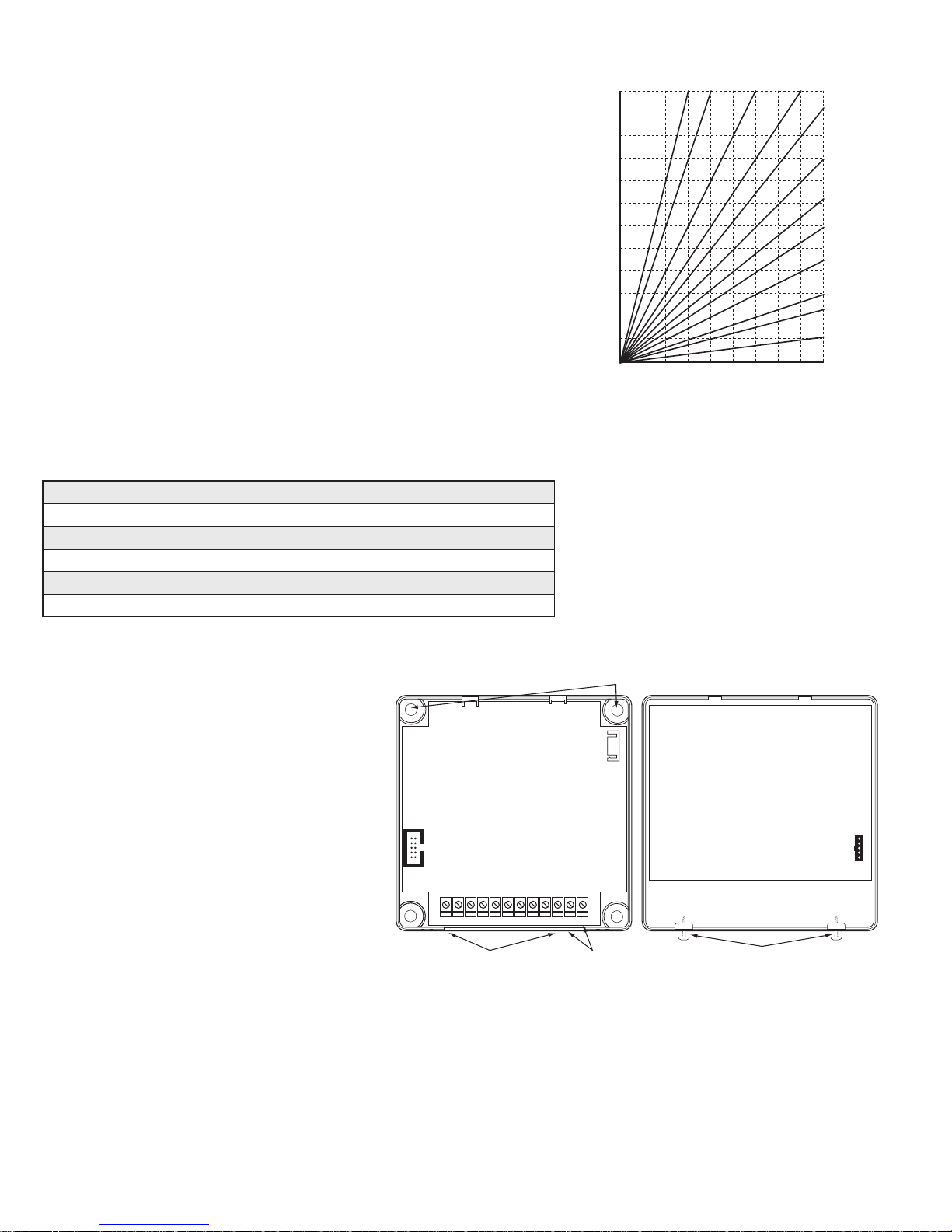
Because of the many different physical characteristics of buildings, and the type of
radiation, i.e., baseboard or radiant, the heat loss varies. In one building, a 1-degree
temperature change outdoors may require a change of 1 degree in heating water
temperature; for another it may require a change of 2, 3, or even 4 degrees in order
to gain the desired comfort level. This is known as the Reset Ratio. The middle chart
shows the wide range of Reset Ratios available for the VSP Elite.
The installer ts the VSP Elite to a specic building by adjusting the Reset Ratio
curve. With curve 4 (2:1 reset ratio) a 2-degree change in outdoor temperature will
change the circulating hot water temperature by 1 degree; at curve 11 (1:3 reset ratio)
an outdoor change of 1 degree will change the water temperature by 3 degrees. Most
buildings with baseboard radiation require curve 6, 7, or 8. Radiant heat applications
usually require a lower curve. Another, is a Setback input that will switch the
heating system to a lower set point determined by the Set Back setting.
Type of Radiation in Building Reset Ratio Offset
Radiators (Steel & Cast Iron) 1.00 (O) : 1.00 (S) 0˚F
Baseboard (Finned copper tube& Cast Iron) 1.00 (O) : 1.00 (S) 0˚F
Radiant (High Mass/Concrete) 4.00 (O) : 1.00 (S) -10˚F
Radiant (Low Mass/Joists) 2.00 (O) : 1.00 (S) -10˚F
Fan Coils & Air Handlers 1.00 (O) : 1.00 (S) 20˚F
2
The Boiler Return water sensor and well are provided
to avoid thermal shock to the boiler and, therefore, to
help prolong boiler life. If the sensor registers that the
boiler return water is colder than 120°F, the VSP Elite
immediately lowers the temperature of the circulating
heating water to reduce the load on the boiler,
allowing the return water temperature to rise.
Mounting the Controller
• The VSP Elite is designed to mount on a 1900
(4”x4”) deep electrical box.
• If additional room is needed for wiring use the
extension skirt provided in the box.
• Place the VSP Elite in a convenient location near
the unit to be controlled.
• Mount the VSP Elite indoors and away from
excessive heat or cold.
• Partially unscrew the Display Cover Mounting
screws. This allows for its removal.
• Lifting the Display Section away from the base will unplug it from the Base section.
• Proceed with the power and output wiring instructions.
• Use the screws provided to mount the VSP Elite to the 1900 box or the extension skirt.
• Mount Display Section back to the Base Section. Tighten the Display Cover Mounting Screws.

3
120VAC Power Source
BLACK
BLACK
System
Strap-On
Sensor
Shield
Not connected
Plastic
Tie-Wraps
Around Pipe
Outdoor
Sensor
snap-in
location
Shield
not connected
Conduit
Outdoor Label
on back of Sensor
Outdoor Sensor
Strap-On Sensor
Mounting
screws
location
Seal around
sensor and wall
Outdoor
drip-hole
T1
T2
COM
COM
T3+
T3-
EXT+
EXT-
P+
P-
COM
24VAC
Enable/Disable
Dry Contact
Boiler
SYS
Pump
DHW
Pump
SET
®
C O R P O R A T I O N
R
SYSTEM = 147F
TARGET = 150F
Outdoor
Sensor
System
Sensor
DECREASE SYSTEMINCREASE
Setback
Dry Contact
Boiler Return
Sensor
VSP Digi-Elite Installation & Operation Manual
Wiring
Wiring Power Input
The VSP Elite is designed to accept 120VAC using the two Black wires. Heat-Timer
recommends the installation of a Surge Suppressor and a Power Switch before the Power
Line connection for safety and ease of service.
• Attach line voltage, 120VAC, to the two Black wires extending from the back of the
VSP Elite. Remember to use the power line from a different source than the equipment
being controlled.
Wiring Input Terminals
System (T1, COM) Sensor Installation
• Place the System sensor in the Secondary Loop past the pump where it will register the temperature of
the loop before any takeoffs.
• Insert the Brass Tube sensor provided (HT #904250-00) into a ⅜" ID ½" NPT immersion well (HT
#904011-00).
• The sensor wires can be extended up to 500' using a shielded 2-conductor cable (Belden #8760 or
equivalent (#18/2)). Do not ground the shield at the sensor but at the control using the COM terminal.
• Do not run sensor wires in conduit with line voltage wiring.
Boiler Return Sensor Installation (T3+, T3-)
• The provided Boiler Return Sensor is designed to be installed in the provided ⅜” ID immersion well.
• The sensor should be located where it will register the correct return from all loops to boiler.
• The sensor wires can be extended up to 500’ by splicing it with shielded 2-conductor cable (Belden
#8760 or equivalent (#18/2)).
• The sensor has no polarity. Connect either sensor wire to the front terminal marked T3±. Connect the other sensor wire and the
shield to the front terminal marked T3-. Do not ground the shield at the sensor.
• Do not run sensor wires in conduit with line voltage wiring.
Outdoor Sensor Installation (T2, COM)
• The Outdoor Sensor must be used when Outdoor Reset is selected as the Control Mode from the Startup menu. However, in Set
Point mode, the Outdoor Sensor is optional. When connected in that mode, it will be used as an input for the Outdoor Cutoff only.
• Only use the Heat-Timer outdoor sensor provided (HT# 904220-00).
• Place the sensor in the shade on the north side of the building.
• Be sure the location is away from doors, windows, exhaust fans, vents, or other heat or cool sources.
• The sensor should be mounted approximately 10' feet above ground level.
• Adhere the Outdoor Label provided to the back of the sensor base.
• Use the Enclosure Base bottom knockout for the conduit. Use the conduit locknut
to hold the conduit and enclosure base together. Screw the cover to the base.
• If screws are used to afx the enclosure to the wall, make sure to seal around the
sensor and wall except from the bottom.
• The sensor wires can be extended up to 500' using shielded 2-conductor cable
(Belden #8760 or equivalent (#18/2)).
• Cut the shield and do not connect it at the sensor end. Only connect it at the control
end using the outdoor terminal marked COM.
• Do not run sensor wires in conduit with line voltage wiring.
Determining the proper location for the Outdoor Sensor is very important.
The VSP will base the heat on the outdoor temperature information it
receives from this location. If the sensor is in the sun, or covered with
ice, its reading will be different from the actual Outdoor temperature (O).
ALERT

Wiring the Enable/Disable (EXT+, EXT-)
EXT+ EXT-
P+ P-
COM 24VAC
Setback/Boost
Wiring
Floating
Motorized
Valve
OPEN.
COM
CLOSE
Boiler
SYS
Pump
DHW
Pump
SET
®
C O R P O R A T I O N
R
SYSTEM = 147F
TARGET = 150F
120 VAC
System/Secondary
Loop Pump
Power (Black)
(Yellow)
120 VAC
VSP Output Wiring
DECREASE SYSTEMINCREASE
Injection Pump
(White)
120 VAC
L
N
L
N
L
N
T3-
EXT+ EXT-
P+ P-
COM 24VAC
Enable/Disable
Wiring
T3-
EXT+ EXT-
P+ P-
COM 24VAC
Setback/Boost
Wiring
N.O.
N.O.
Floating
Motorized
Valve
OPEN.
COM
CLOSE
• The EXT± terminals can be used to enable or disable the system by connecting it to a thermostat, external
control, or a switch. It accepts dry contact input only. No voltage can be placed across these terminals.
• If no thermostat or control is connected to the EXT± terminals, leave the jumper supplied as a contact to the
terminals. The VSP Elite will not provide heat unless the EXT± terminals are closed/shorted.
Wiring the Setback/Boost (P+, P-)
• The Setback feature can be used to provide a lower temperature Set Point when less heat is required.
• A typical use for Setback is to provide less system temperature during the night or on the weekends, but heat is
still required.
• The Setback is activated by closing/shorting the P± terminals using an external timer.
• The Setback can accept only dry-contact input. No voltage can be placed across these terminals.
Wiring Outputs
Wire Colors and Output Lights
• The VSP Elite has a one N.O. S.P.S.T. (Single-pole single-throw) relay rated at 1A pilot load (⅛ HP).
• The VSP Elite has three LED lights. The right most LED represents the System relay operation. When the relay energizes, its LED
will turn on.
• The other two LEDs blinks when the Injection pump increase or decrease its speed.
• Both pump outputs are dry contacts only. They do not source any power.
• The two Yellow wires control the System pump relay and the right LED.
• The two White wires control the injection pump.
4
Wiring the System Pump
• The Secondary Loop/System pump is the one circulating the water in the Secondary Loop.
• The VSP Elite will control the Secondary Loop / System Pump up to a maximum output of 1 Amp inductive or 1/8 HP.
• Wire the two Yellow wires to the System Pump circuit.
• The VSP Elite does not source any output power to the pump. The
relay makes when energized to switch the power to the pump.
Wiring the Injection Pump
• The Injection pump is the one installed on the Injection Loop
between the Secondary Loop and the Boiler Loop.
• The VSP Elite will control the Injection Pump up to a maximum
output of 1.2 Amp (1/8 HP) (i.e. B&G NRF-33, Taco 0010,
Grundfos 26-64, or equivalent). The pump must be of the
permanent split capacitor type.
• Wire the two White wires to the Injection Pump circuit. They must
be in series with the pump power. The signal cannot be wired
• The VSP Elite does not source any output power to the pump. A
through any pilot duty relay or pump starter.
separate power source is required for pump operation. What the VSP Elite does is change the electric signal powering the pump to
achieve the desired speed need to achieve or maintain the target set point.
• After installing the Injection Pump, it is important to set the Minimum Speed Adjustment to guarantee injection pump ow at all
levels. See Minimum Speed Adjustment on page 13.
5
Secondary
Loop
Boiler Loop
Pump
Injection
Pump
Injection
Loop
Return Sensor
System
Sensor
Boiler
Loop
Secondary
Loop
Pump
Balancing
Valve
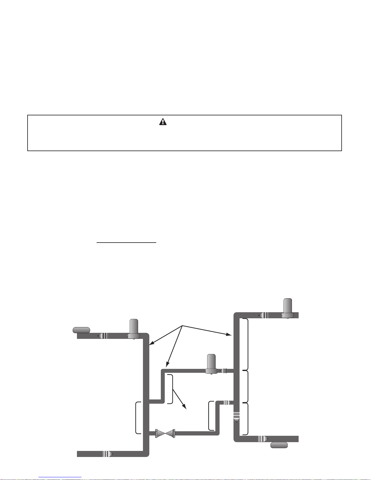
Maximum 4
Pipe Diameter
Min. of 1’ pipe drop
as thermal trap
Minimum 8 Pipe
Diameters Upstream
Minimum 4 Pipe
Diameters Downstream
Maximum 4
Pipe Diameter
Injection Loop Pipe diameter
is at least one size smaller than
Boiler Loop and Secondary Loop
VSP Digi-Elite Installation & Operation Manual
Piping Design
When designing an injection systems, it is eminent that the Boiler Loop and the Secondary Loop are completely isolated. This can be
achieved by following these simple rules (see Injection Piping Rules on page 5.):
• The Injection piping size must be at least one pipe size smaller than smaller of the Boiler Loop and the Secondary Loop piping.
• The distance between the Injection Loop tees on any of the other loops must not exceed 4 loop pipe diameters.
• After the injection pipe tee, there must be a minimum of 8 pipe diameters upstream the tees and a minimum of 4 pipe diameters
downstream the tees on the Boiler Loop side to prevent any jet ow.
• A vertical drop of a minimum of one foot on each of the supply and return pipes of the Injection Loop will act as a thermal trap to
prevent the Boiler Loop from supplying the Secondary Loop with heat when the injection pump is off.
• A circuit setter or globe or balancing valve can be used on the return leg of the Injection Loop to accurately balance the system.
• The Injection Pump must be of the permanent split capacitor type with a fraction horse power motor.
WARNING
The Injection Pump and pipe size selection MUST be done properly by a qualied engineer or trained
technician to insure proper operation and prevent excessive or under heat zones as well as hazardous
situations. The provided piping and pump sizing are general guidelines to help in general cost estimation.
Injection Pump and Pipe Size
To size the system properly, start by calculating the Injection Heat Load. To select a pump, use the formula to calculate the Injection
Flow Rate. Then, select a pump size, pipe size, and valve size based on the predetermined conguration provided.
• Total Injection Heat Load (Btu/Hr) for the secondary loop
• Boiler Loop Temperature (TB)
• Secondary Loop Temperature (TS)
• The design differential between the Secondary Loop supply and return temperatures (ΔTS)
• Injection Flow Rate (Gal/Min)
Injection Flow Rate =
The Injection pump, pipe size, and valve size combination can then be selected from the table;
Injection Heating Load
500 x (T
- TS + ΔTS)
B
Injection Piping Rules
 Loading...