

heat-timer Digi-span SPC TEMP Installation & Operating Instructions Manual
INSTALLATION/OPERATING INSTRUCTIONS
R
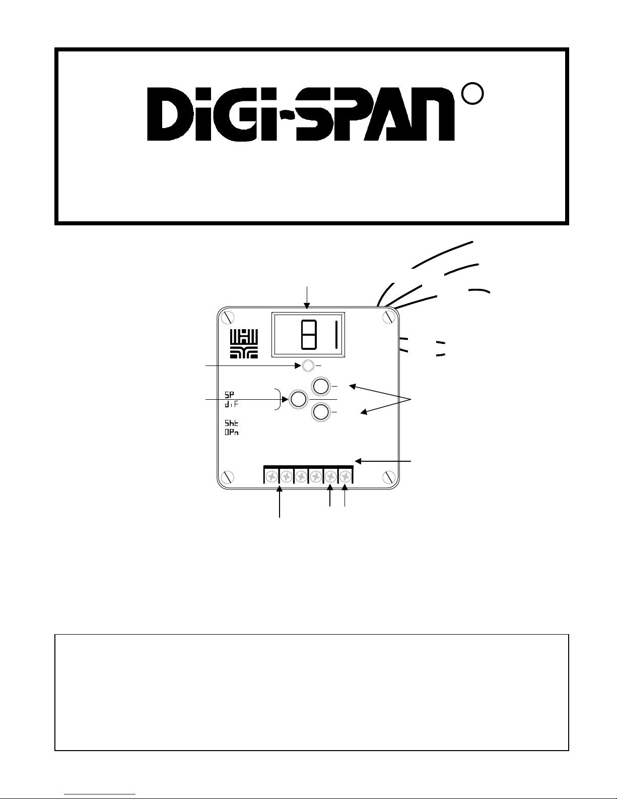
SPC TEMP
Digital Set Point Control
Temperature Range -30 to 250°F (-35 to 120°C)
Output light indicates
status of relay
Push this button to display
the set point or differential
Wire sensor provided with
the unit to these terminals
Digital display reads
sensor value constantly
OUTPUT
= Set Point
= Differential
= Shorted Sensor
= Open Sensor
SENSOR 24VAC
UP
PRESS TO READ
DOWN
(+) (-)
To use 12VDC connect
to these terminals
observing the polarity
Black
Blue
Blue
Output
wires
Red
White
To use 120VAC
power connect to
these wires
Push these buttons to adjust
the set point or differential
To use 24VAC power
connect to these two
terminals
Warning: This Heat-Timer control is strictly an operating control; it should never be used as a primary
limit or safety control. All equipment must have its own certified limit and safety controls required by local
codes. The installer must verify proper operation and correct any safety problems prior to the installation
of this Heat-Timer control.
This Heat-Timer device was thoroughly tested for defects and workmanship before leaving our factory. We do warrant the equipment to
be free of defects under normal use for a period of one year from the date of installation. Transportation charges for factory repairs must
be prepaid. Damage to the Heat-Timer device or any of its components due to misuse, abuse, improper installation, or caused by power
failures, fire, flood, or lightning are not covered by this warranty. The company assumes no liability for indirect or consequential damages
of any nature. This Heat-Timer warranty applies only to the original purchaser/user, is not assignable or transferable, and does not cover
damage to the device occurring in shipment. Any service, repairs, modifications or alterations to the unit not expressly authorized by the
company will invalidate the warranty. This warranty is in lieu of all other warranties expressed or implied.
LIMITED ONE YEAR WARRANTY
1

INSTALLATION
Mounting the Controller
• The SPC is designed to mount on a 1900 (4”x4”) electrical box.
• If the SPC is to be panel mounted, or if additional room is needed for wiring, an extension skirt is available*.
• Locate the SPC in a convenient location near the unit to be controlled.
• Mount the unit away from excessive heat or cold. Ambient operating temperature is from 20 to 120°F .
• After completing all the wiring connections (see below) use the two screws provided to mount the SPC to the 1900 box.
Installing the T emperature Sensor
• The temperature sensor wires can be extended up to 500’ by splicing with 18 gauge shielded wire.
• Do not run wires in conduit with line voltage.
• If measuring liquid temperature, the sensor should be inserted into a 3/8” ID well (HT#904011 or equivalent).
• The SPC will operate based on the temperature it reads at the sensor location. Therefore, select a sensor location which is
representative of the entire system.
Wiring the Sensor
• The sensor wires can be connected to the two screws on the front of the SPC marked SENSOR.
• The wires can also be connected to the rear of the SPC using the Rear Wire connector*. Connect the sensor wires to the
orange and yellow wires from the Rear Wire connector .
• Polarity is not important. Either wire from the sensor can be connected to either SPC sensor input.
Wiring the Power - SPC can use either 120VAC, 24VAC, or 12VDC
120V AC
• Attach line voltage to the two blue wires extending from the back of the SPC.
• Use wire nuts, or wrap the connections with electrical tape.
• Class 1 voltages must enter the enclosure through a different opening from any Class 2 wiring.
24V AC
• Use a dedicated transformer with at least a 5VA output.
• Bring 24VAC to the two screws on the front of the SPC marked 24V AC
• 24VAC can also be connected to the rear of the SPC using the Rear Wire connector*. Connect the 24VAC to the violet and
gray wires from the Rear Wire connector .
12VDC
• The polarity of the connection is important. If the polarity is reversed, the SPC will not be damaged. However, it will not
operate unless the polarity is corrected.
• Bring the (+) side of the 12VDC to the inner screw marked 24V AC (see front page). Bring the (-) side of the 12VDC to the
outer screw marked 24V AC.
• 12VDC can also be connected to the rear of the SPC using the Rear Wire connector*. The (+) side of the 12VDC must be
connected to the connector’s violet wire. The (-) side of the 12VDC must be connected to the connector’s gray wire.
* The Optional Mounting Kit
includes the extension skirt,
the Rear Wire connector , and
an input terminal cover. Order
separately as HT #908520.
SENSOR
TYPICAL WIRING DIAGRAM
WHITE
RED
BLACK
UNIT
POWER
HOT
NEUTRAL
WARNING
The SPC can accept only one
source of power: 120VAC,
24V AC, or 12VDC. If more than
one power source is applied, the
unit may be damaged.
24 VAC
12VDC
or wire 120VAC to rear
transformer (Blue Wires)
HEATER
or CHILLER
UNIT
2
 Loading...