

heat-timer Digi-Span Elite HWE-SS Installation And Operation Instructions Manual
INSTALLATION AND OPERATION INSTRUCTIONS
R
Blue (Boiler Output)
White (DHW Pump Output )
Yellow (System Pump Output )
Boiler
SYS
Pump
DHW
Pump
SET
®
C O R P O R A T I O N
R
SYSTEM = 147F
TARGET = 150F
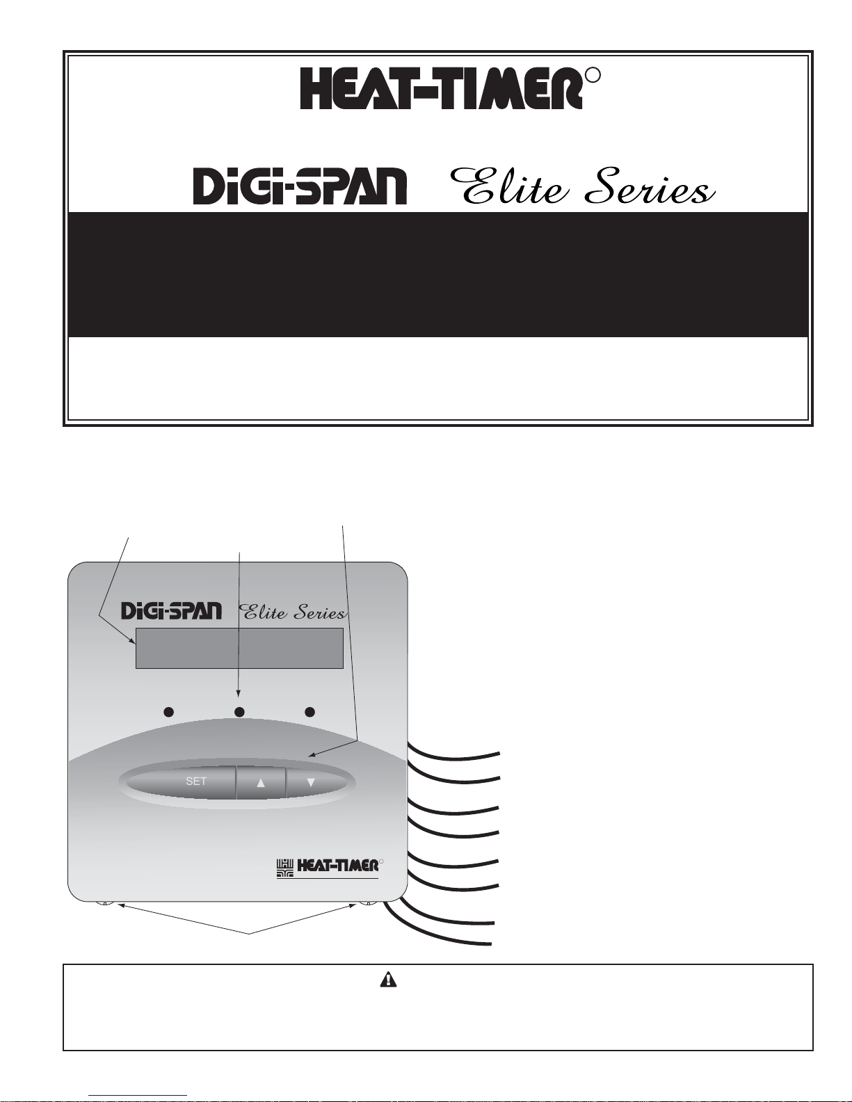
2 Line Alphanumeric Display
Displays sensor values and
menu settings
Output Lights indicate
output status
Display Section Locking Screws
Black (120VAC power)
3 Buttons to operate
the control
®
Elite Series
HWE-SS DIGI-El I t E
Hydronic Single-Stage Boiler Control
Hot Water Control with Outdoor Reset, Set Point,
and DHW for Hydronic Heating Applications
The HWE-Single Stage (HWE-SS) DIGI-SPAN Elite establishes
ambient comfort by varying the temperature of the heating
system’s circulating hot water in response to changes in the outdoor
temperature. In addition, it provides an outdoor temperature based
cutoff, heating system pump control, and domestic hot water (DHW)
pump control. Two new features have been added to this control
including a customized reset ratio curve. A Set Point option was
added for applications where outdoor reset will not apply.
This Heat-Timer control is strictly an operating control; it should never be used as a primary limit or safety
control. All equipment must have its own certified limit and safety controls required by local codes. The installer
must verify proper operation and correct any safety problems prior to the installation of this Heat-Timer control.
Two sensors are used, one to monitor the outdoor temperature, and
one to monitor the circulating hot water temperature in the heating
system. When the outdoor temperature falls below the Outdoor
Cutoff setting, the heating system is activated and the hot water
temperature is increased proportionally to satisfy the load. Should
it get warmer outdoors, the hot water temperature is automatically
lowered by the control. If the outdoor temperature continues to rise
to the outdoor cutoff setting then the heating system is turned off.
WARNING
2
T1 T2 T3+
COM COM
T3-
EXT+ EXT-
P+ P-
COM 24VAC
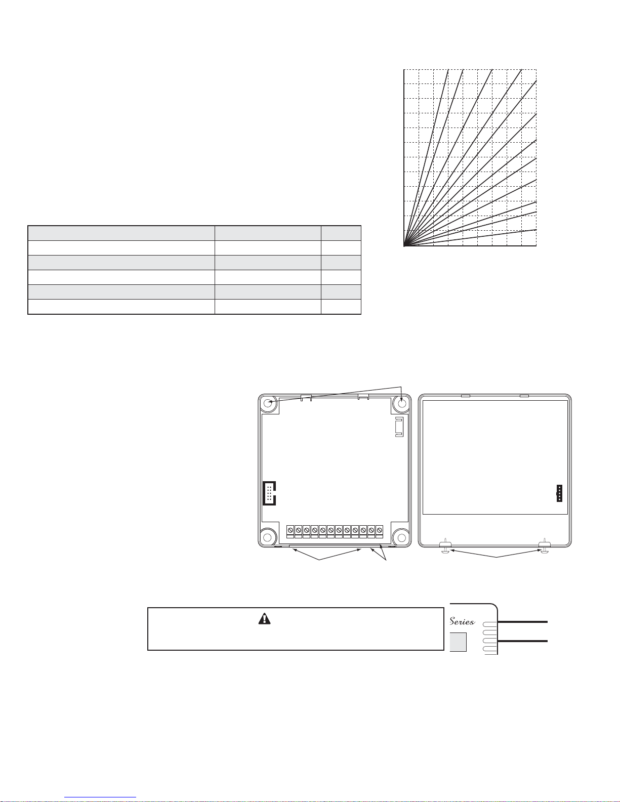
Display Cover Mounting Screws
Display SectionBase Section
Base Mounting Holes
Input Terminals 24VAC optional power input
120VAC Power Source
BLACK
BLACK
Outdoor Temperature (in °F)
70 60 50 40 2030 0 -1010 -20
120
140
130
150
160
170
180
200
190
210
220
100
110
12 11 10 9
8
7
6
4
3
2
5
1
1:4 1:3 1:2 1:1.5
1:1.25
1:1
1.25:1
1.5:1
2:1
3:1
4:1
8:1
Water Temperature (in °F)
Reset Ratio Curves
Reset Ratios are presented as
Outdoor : Water
Because of the many different physical characteristics of buildings, and the type of
radiation, i.e., baseboard or radiant, the heat loss varies. In one building, a 1-degree
temperature change outdoors may require a change of 1 degree in heating water
temperature; for another it may require a change of 2, 3, or even 4 degrees in order
to gain the desired comfort level. This is known as the Reset Ratio. The middle chart
shows the wide range of Reset Ratios available for the HWE-SS.
The installer ts the HWE-SS to a specic building by adjusting the Reset Ratio. With
a curve of 4 (2:1 reset ratio) a 2-degree change in outdoor temperature will change the
circulating hot water temperature by 1 degree; at an 11 curve (1:3 reset ratio) an outdoor
change of 1 degree will change the water temperature by 3 degrees. Most buildings
with baseboard radiation require a curve of 6, 7, or 8. Radiant heat applications usually
require a lower curve. An external T-Stat input can be used to shut the heating system
down when the thermostat is satised. Another, is a Setback input that will switch the
heating system to a lower set point determined by the Set Back setting.
Type of Radiation in Building Reset Ratio Offset
Radiators (Steel & Cast Iron) 1.00 (OD) : 1.00 (SYS) 0˚F
Baseboard (Finned copper tube& Cast Iron) 1.00 (OD) : 1.00 (SYS) 0˚F
Radiant (High Mass/Concrete) 4.00 (OD) : 1.00 (SYS) -10˚F
Radiant (Low Mass/Joists) 2.00 (OD) : 1.00 (SYS) -10˚F
Fan Coils & Air Handlers 1.00 (OD) : 1.00 (SYS) 20˚F
An optional domestic hot water input is provided for systems where an indirect tank provides DHW. During a DHW call, the HWE-SS will
maintain a constant set point of 200°F regardless of outdoor temperature or the status of the optional external thermostat. The DHW pump
will be enabled whenever there is a call for DHW. The heating system pump can be programmed to turn off during the rst hour of a DHW
call. This allows the DHW tank to be satised quickly.
Mounting the Controller
• The HWE-SS DIGI-Elite is designed to mount on a
1900 (4”x4”) deep electrical box.
• If additional room is needed for wiring use the
extension skirt provided in the box.
• Place the HWE-SS in a convenient location near
the unit to be controlled.
• Mount the HWE-SS indoors and away from
excessive heat or cold.
• Partially unscrew the Display Cover Mounting
screws. This allows for its removal.
• Lifting the Display Section away from the base will
unplug it from the Base section.
• Proceed with the power and output wiring
instructions.
• Use the screws provided to mount the HWE-SS to the 1900 box or the extension skirt.
• Mount Display Section back to the Base Section. Tighten the Display Cover Mounting Screws.
Wiring
Wiring Power Input
The HWE-SS is designed to accept ONLY A SINGLE POWER SOURCE. It can be wired to either 120VAC using the two Black
wires or 24VAC using the right most two terminals on the terminal block on bottom of the control. Heat-Timer recommends the
installation of a Surge Suppressor and a Power Switch before the Power Line connection for safety and ease of service.
120VAC
• Attach line voltage, 120VAC, to the two Black wires extending from the back of the HWE-SS. Remember to use the power line
from a different source than the equipment being controlled.
The HWE-SS can accept only one source of power: 120VAC or 24VAC.
If more than one power source is applied, the unit may be damaged.
WARNING

3 HWE-SS Elite Installation and Operation Manual
T1 T2 T3+
COM COM
T3-
EXT+ EXT-
P+ P-
COM 24VAC
Input Terminals
System Sensors
{
Enable/Disbale Input
Dry-Contact
{
{
Outdoor Sensor
{
24VAC power Input
{
DHW Input Dry-Contact
Setback Input Dry-Contact
{
N.O.
S.P.S.T. Output Wiring 120VAC Power Wiring
120VAC Power Source
BLACK
BLACK
Boiler
N.O.
P+ P-
COM 24VAC
24VAC
Comm
24VAC Power Wiring
N.O.
ORANGE
System Pump
Output Wiring
N.O.
VIOLET
DHW Pump
Output Wiring
T1 T2 T3+
COM COM
T3-
EXT+ EXT-
P+ P-
COM 24VAC
DHW Call
Wiring
T1 T2 T3+
COM COM
T3-
EXT+ EXT-
P+ P-
COM 24VAC
Setback/Boost
Wiring
N.O.
S.P.S.T. Output Wiring 120VAC Power Wiring
120VAC Power Source
BLACK
BLACK
Boiler
Output Wiring
N.O.
YELLOW
T1 T2 T3+
COM COM
T3-
EXT+ EXT-
P+ P-
COM 24VAC
24VAC
Comm
24VAC Power Wiring
Shield
Shield
System Temp
Outdoor Sensor
Sensor Wiring
Enable/Disable
Wiring
Input Terminals
N.O.
ORANGE
System Pump
Output Wiring
N.O.
VIOLET
DHW Pump
Output Wiring
T1 T2 T3+
COM COM
T3-
EXT+ EXT-
P+ P-
COM 24VAC
DHW Call
Wiring
T1 T2 T3+
COM COM
T3-
EXT+ EXT-
P+ P-
COM 24VAC
Setback/Boost
Wiring
System
Strap-On
Sensor
Shield
Not connected
Plastic
Tie-Wraps
Around Pipe
Outdoor
Sensor
snap-in
location
Shield
not connected
Conduit
Outdoor Label
on back of Sensor
Outdoor Sensor
Strap-On Sensor
Mounting
screws
location
Seal around
sensor and wall
Outdoor
drip-hole
T1
T2
COM
COM
T3+
T3-
EXT+
EXT-
P+
P-
COM
24VAC
Boiler
SYS
Pump
DHW
Pump
SET
®
C O R P O R A T I O N
R
SYSTEM = 147F
TARGET = 150F
US
C
U
L
R
ENCLOSED
ENERGY
MANAGEMENT
EQUIPMENT
LISTED
99RA
120 VAC
Power Source
DHW Pump (White)
System Pump (Yellow)
Boiler
(Blue)
Power (Black)
N
L
120 VAC
Power Source
HWE-SS POWERED WITH 120VACHWE-SS POWERED WITH 24VAC
120 VAC
Power Source
DHW Pump (White)
System Pump (Yellow)
Boiler
(Blue)
N
L
24VAC
• Use a dedicated transformer with at least a 5VA output.
• Bring 24VAC to the two right most terminals on the front of the HWE-SS marked 24VAC and COM.
Wire Colors and Output Lights
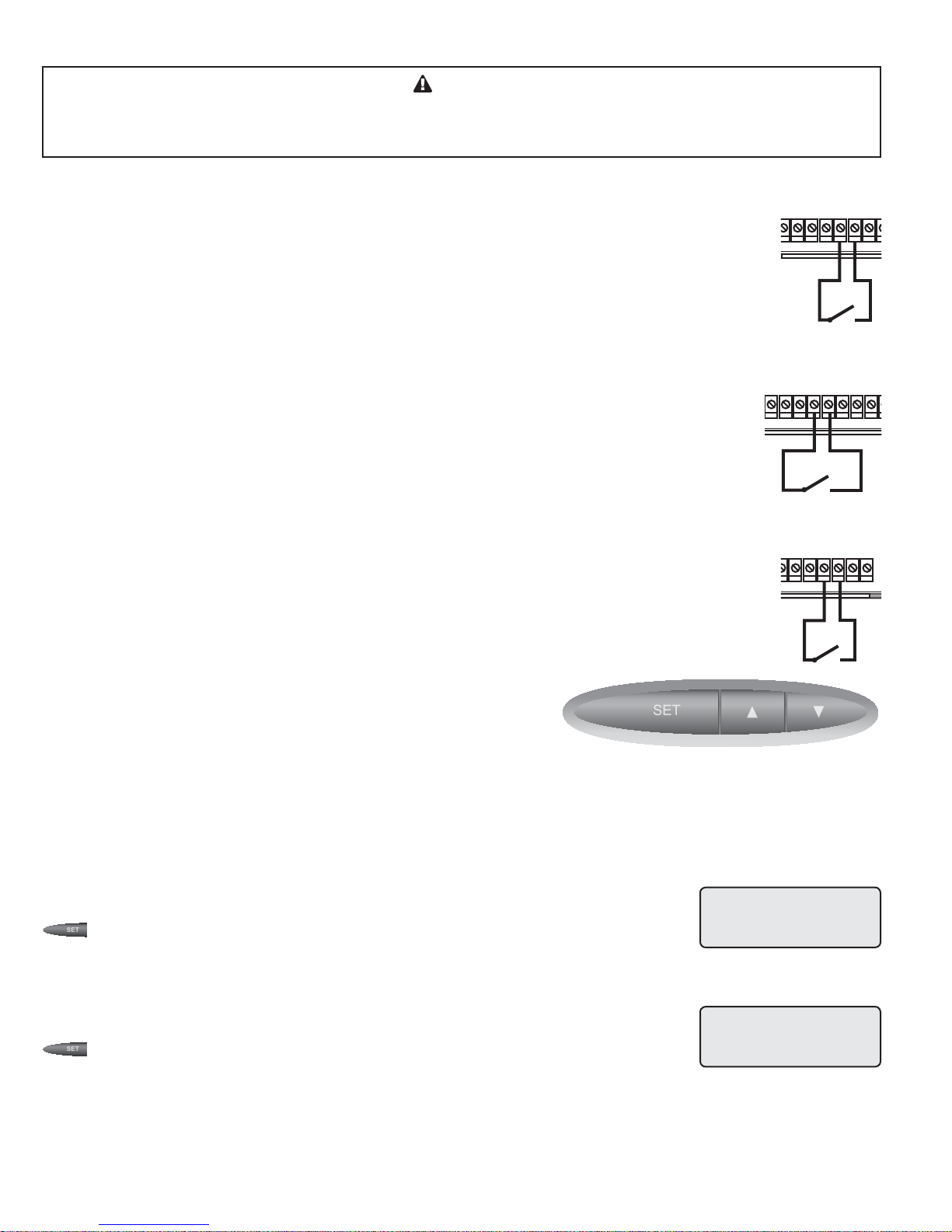
• The HWE-SS has a three S.P.S.T. (single-pole single-throw N.O.) relays.
• The HWE-SS has three LED lights that follow the output relays operation.
• The outputs are dry contacts only. They do not source any power.
• The two Blue wires represent Boiler Output relay and the left LED.
• The two Yellow wires represent System Output relay and the middle LED.
• The two White wires represent DHW Output relay and the right LED
Boiler Wiring
• The boiler output relay is N.O. dry contact. It does not source any power.
• Wire the N.O. Blue wires in series with the boiler’s limit circuit.
• Class 1 voltages must use a different wiring conduit and knockout from any Class 2 voltage.
System and DHW Pump Wiring
• The pump output relays are N.O. dry contacts only. They do not source any power. Each
relay can operate up to 1/8 HP pump (1 Amp Inductive load).
• The System output relay (Yellow wires) will energize whenever the outdoor temperature drops
below the Outdoor Cutoff.
• The DHW output relay (White wires) will energize whenever there is a DHW call.
• Class 1 voltages must use a different wiring conduit and knockout from any Class 2 voltage.
Wiring Input Terminals
Heating System Sensor (HSS) Installation (T1, COM)
• Place the Heating System sensor in the common header where it will register the output of the
boiler before any takeoffs.
• Only use a Standard Brass Tube sensor provided (HT# 904250-00).
• The sensor wires can be extended up to 500' using a shielded 2-conductor cable (Belden #8760 or equivalent
(#18/2)). Do not ground the shield at the sensor but at the control using the COM terminal.
• Do not run sensor wires in conduit with line voltage wiring.
• Install a 3/8"ID 1/2"NPT immersion well (HT #350147-00 or equivalent).
• Insert the supplied sensor probe into the well.
Outdoor Sensor Installation (T2, COM)
• The Outdoor Sensor must be used when Outdoor Reset is selected as the Control
• Only use the Heat-Timer outdoor sensor provided (HT# 904220-00).
• Place the sensor in the shade on the north side of the building.
• Be sure the location is away from doors, windows, exhaust fans, vents, or other
• The sensor should be mounted approximately 10' feet above ground level.
• Adhere the Outdoor Label provided to the back of the sensor base.
• Use the Enclosure Base bottom knockout for the conduit. Use the locknut to
• If screws are used to afx the enclosure to the wall, make sure to seal around the
• The sensor wires can be extended up to 500' using shielded 2-conductor cable.
• Cut the shield and do not connect it at the sensor end. Only connect it at the
• Do not run sensor wires in conduit with line voltage wiring.
Mode from the Startup menu. However, in Set Point mode, the Outdoor Sensor
is optional. When connected in that mode, it will be used as an input for the
Outdoor Cutoff only.
heat sources.
hold the conduit and enclosure base together. Screw the cover to the base.
sensor and wall except from the bottom.
control end using the outdoor terminal marked COM.
4
SET
SET
SET
T3-
EXT+ EXT-
P+ P-
COM 24VAC
Enable/Disable
Wiring
N.O.
DHW Pump
T3-
EXT+ EXT-
P+ P-
COM 24VAC
Setback/Boost
Wiring
N.O.
120VAC Power Source
BLACK
BLACK
N.O.
ORANGE
System Pump
Output Wiring
N.O.
VIOLET
DHW Pump
Output Wiring
COM COM
T3-
EXT+ EXT-
P+ P-
COM 24VAC
DHW Call
Wiring
T1 T2 T3+
COM COM
T3-
EXT+ EXT-
P+ P-
COM 24VAC
Setback/Boost
Wiring
EXT+ EXT-
P+ P-
COM 24VAC
Setback/Boost
Wiring
ALERT
Determining the proper location for the Outdoor Sensor is very important. The HWE-SS will base the heat on
the outdoor temperature information it receives from this location. If the sensor is in the sun, or covered with
ice, its reading will be different from the actual Outdoor temperature (OD).
Wiring the Domestic Hot Water Call DHW (T3+, T3-)
• DHW can be used to raise system Set Point to the lower of 200°F or Maximum Target temperature.
• DHW Call terminals are dry contact N.O. terminals.
• Wire an aquastat or another control to provide contact closure on the DHW Call terminals.
Wiring the Enable/Disable (EXT+, EXT-)
• The EXT terminals can be used to enable or disable the system by connecting it to a thermostat, external control,
or a switch. It accepts dry contact input only.
• If no thermostat or control is connected to the EXT terminals, leave the jumper supplied as a contact to the
terminals.
• No outputs will be active unless the EXT terminals are closed/shorted.
Wiring the Setback/Boost (P+, P-)
• The Setback feature can be used to provide the HWE-SS with a lower temperature Set Point when less heat is
required.
• A typical use for Setback is to provide less system temperature to a building during the night or on the
weekends when building is not occupied, but heat is still required.
• The Setback is activated by closing/shorting the P+ and P- terminals using an external timer.
Button and Navigating Menus
The HWE-SS has three buttons.
• The SET button function varies. When the Default Screen is displayed, pressing the SET Button views the
MENU. When in the Menus and settings, the SET Button accepts the selected entry or setting value.
• When in the menus, pressing the Up and Down buttons will scroll through the menu options. They can be used
to change the setting of a specic function. i.e., change the Set Point, Differential, or System Trim. In addition,
when in the default screen, the Up and Down buttons will display the outdoor
temperature and Outdoor Cutoff.
• At the end of every operation menu there is a <Back> option that allows the
user to go back one menu level. If the SET Button was held down for three
seconds on the <Back> option, the display will go back to the default screen.
Startup Options
When the control is initiated for the rst time or after a manual reset, it will start its operation with the Startup Menu. Later, the
Startup menu can be accessed as an option from the operation menu. An option must be accepted in each screen in the Startup Menu
to move to the next level.
Display Unit
Options: ºF, ºC Default: ºF
/<System Startup>/Display Unit
• The HWE-SS will offer two different temperature displays. If ºF is selected, all temperatures will
display in Fahrenheit. If ºC is selected, all temperatures will display in Celsius.
Control Mode
Options: Outdoor Reset, Set Point Default: Outdoor Reset
/<System Startup>/Display Unit/Control Mode
• The new HWE-SS have two heating logics. Outdoor Reset; varies the system set point/target
based on outdoor temperature. This selection will add several menu options, Reset Ratio, Offset, Min Water temp, Max Water temp,
and Outdoor Cutoff, to allow of adjustment and ne tuning of the Reset Curve. In addition, a customized curve will be available for
specialized applications.
• Set Point; Gives the installer the exibility of selecting a xed set point. The Outdoor Cutoff will be available if an outdoor sensor
was installed.
DISPLAY UNIT:
F
C
CONTROL MODE:
Outdoor Reset
Set Point
 Loading...