

Page 1
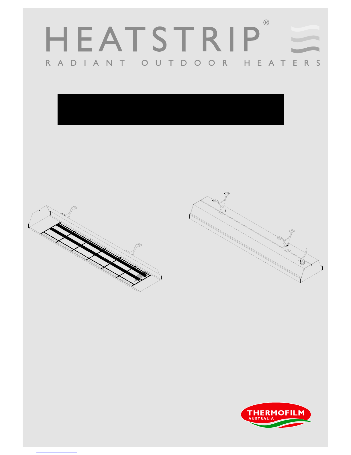
OPERATION, INSTALLATION AND MAINTENANCE MANUAL
HEATS T R I P® Max
The heater that i s a d e s i g n f e a t u r e !
Page 2

2
Product Overview Rev G MAR16
Why choose Heatstrip® electric radiant heaters for your outdoor or hard-to-heat indoor area?
As there is typically constant air movement in an outdoor or open indoor area, many conventional patio heaters rely on
convection heating which works by heating the surrounding air. This can be quite impractical for these areas, as this
heated air can easily blow away with natural air movement. Radiant style heaters transfer heat directly to objects through
infra-red waves.
Whilst convection heaters heat the air in between objects, radiant heaters heat the surface of the objects themselves.
HEATSTRIP® electric radiant heaters are more effective within an outdoor or uninsulated indoor area because they
provide targeted warmth directly to the people and objects in their path.
Discrete, stylish heating for undercover outdoor and indoor open areas
Using the radiant heating principle, HEATSTRIP® can provide effective and energy efficient comfort heating for undercover
outdoor and indoor open areas. HEATSTRIP® has successfully enabled many entertainment venues such as restaurants,
pubs and clubs to utilise their outdoor dining areas day and night, through all seasons. Within your workplace or business,
HEATSTRIP® can provide comfort heating for designated outdoor smoking and leisure areas, as well as for workstation
spot heating in factories, warehouses and showrooms. Within your home, HEATSTRIP® can provide comfort heating for
undercover alfresco dining and BBQ area, patios, verandas, courtyards and balconies.
APPLICATION THS THH THX
Indoor insulated areas, classrooms, offices, bathrooms, wet areas, drying rooms
√ √ X
Outdoor under cover, café, veranda, patio, balcony ceiling height 3m or less
X √ X
Outdoor under cover, café, veranda, patio, balcony ceiling height 3m or more
X X √
Highly exposed outdoor area
X X √
Indoor open area, warehouse, factory, production areas, sports facilities
√ √ √
Indoor spot heating, above tables, assembly areas
X √ √
There are 3 different series of products within the Heatstrip® product category. Each has a different temperature output,
making them ideal for different applications. Below is a list of some common applications, to assist with the selection of the
most effective and efficient series. This is a general guide only, please refer to the Product Manual for each product, for
more information.
HEATSTRIP® Classic (THH models) is a premium high temperature heater and is primarily used for outdoor rooms
where there is 1,2 3, or 4 enclosed sides, with an ideal mounting height of 2.1 m to 2.7m.
HEATSTRIP® Max (THX models) is an ultra high temperature heater used for uncovered or open areas with a
mounting height of 2.4 m to 3.5m.
HEATSTRIP® Indoor (THS models) is a medium intensity heater used for protected indoor applications.
Page 3
3
Innovative, High Performance Electric Heating Technology
Features & Benefits
High Output radiant heat
The Heatstrip Max range of electric radiant heaters produces a high temperature radiant warmth that travels through the
air directly to people and surfaces below – similar to the heat rays emited by the Sun. Radiant heating is the only viable
option for outdoor or tough indoor sites.
Unique low-glow heating technology
Specially designed and engineered "low-glow" heating element provides a very gentle and unobtrusive glow. There no
blinding light, like other infra-red heaters, so you can enjoy the experience. Energy is directed towards producing heat,
rather than an annoying light.
Maximum heat performance – multiple applications
The high temperature output of the Heatstrip Max is perfect for exposed outdoor sites, high ceilings and hard-to-heat
indoor and outdoor applications.
The dual element design allows for a very compact unit, and maximum efficiency. Outdoor applications include al-fresco
and dining/entertainment areas, patios, veranda's and balconies, to name a few. Indoor applications such as factories,
warehouses, showrooms, workshops and workstation spot heating are ideal for the Heatstrip Max.
Suitable for permanent outdoor mounting, no protection needed.
For outdoor applications, the Heatstrip Max is suitable for both permanently exposed (eg. courtyards and patios) and
undercover installations - does not need to be fully protected from the elements.
High Strength element – virtually indestructible
The unique metallic “Incoloy” element is 14mm thick, meaning it is vandal proof and will not shatter like other glass quartz
heating elements. Provides piece of mind in both commercial and domestic situations.
Commercial grade quality – 2 years full replacement warranty
Constructed of extremely robust, commercial grade material, the Heatstrip Max is designed for long-life and durability in all
conditions. It is fully supported by a 2 year replacement warranty under both residential and commercial conditions.
Corrosion protection
Built from corrosion resistant alloy, it is suitable for use in most applications, including difficult corrosive environments such
as coastal areas.
Multi-Purpose Mounting Options
The Heatstrip Max is supplied with flexible mounting options. The standard bracket will allow both ceiling and wall
mounting, at various angles, as well as suspension by chains/wires and metal rods. Optional twin mount and end-to-end
brackets are also available.
2 models – DIY or hard-wired
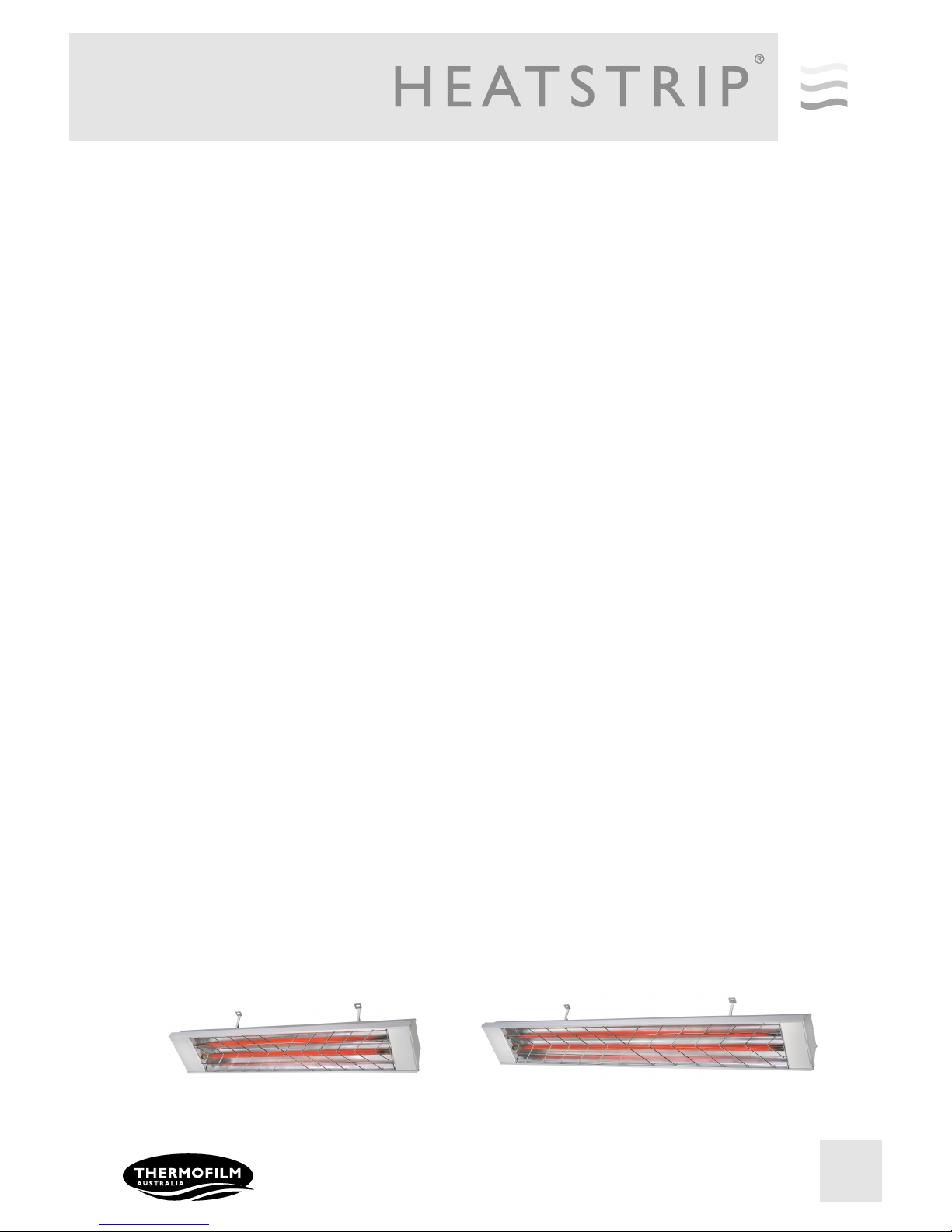
2 models are available. The THX 2400 (2400W) is supplied with a lead and plug, therefore ideal for a DIY installations.
The THX 3600 (3600W) requires hard-wiring to a 15amp power supply.
Australian designed, engineered and assembled
Page 4
4
Specifications - Australia
MODEL POWER
(WATTS)
CURRENT
(AMPS)
DIMENSIONS
(mm)
WEIGHT
(Kg)
LEAD
LENGTH
(mm)
PLUG
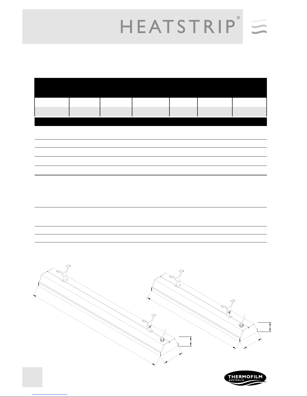
THX2400 2400 10 854 x 170 x 80 5 1000 YES
THX3600 3600 15 1184 x 170 x 80 6 1000 NO
MODEL
HEATER TYPE High intensity electric radiant overhead heater with Incoloy 840 element
OUTPUT Refer to model code chart above
POWER 230-240 Volts Nominal at 50—60 Hertz, Single Phase
CONNECTION 3 Core Cable 2.5mm2
APPROVALS AUSTRALIA/NZ
MOUNTING HEIGHT MINIMUM
RECOMMENDED
MAXIMUM
2.1 m
2.4 m to 3.0 m
3.5 m (For higher ceiling heights, units can be
lowered using optional bracket kits or refer to the
Heatstrip Max range)
MOUNTING OPTIONS Suitable for ceiling, wall, beam mounting. Also available for extension
mount using rigid fixing poles and chain mount bracket.
PROTECTION RATING IPX5 Protection from water ingress from all directions
COUNTRY OF MANUFACTURE Australia
170
854
1180
170
80
80
Page 5
5
BAR
BAR STOOLS
DINING TABLE
LOUNGE
BBQ
Spot heating principle
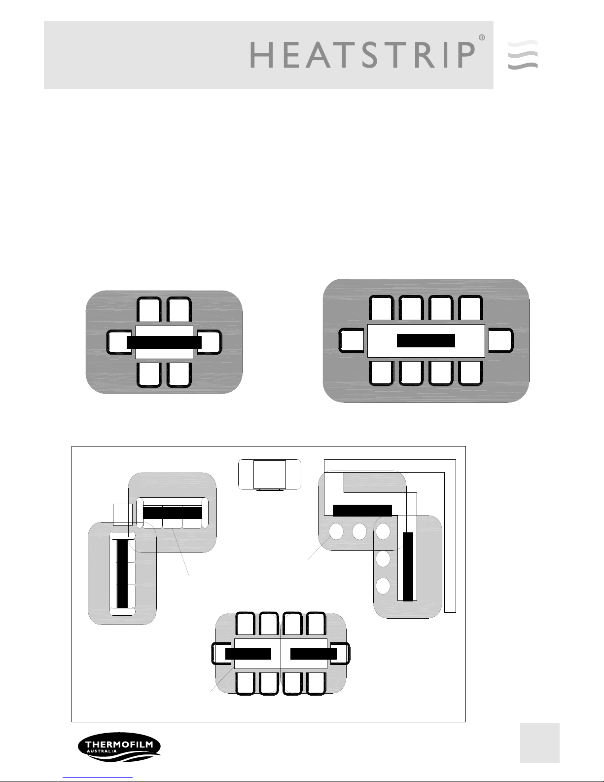
In most outdoor or difficult-to-heat indoor applications, therefore are 2 options when looking at the size and quantity of the heater required. Option 1 is to comfort heat the entire area based on the total dimensions of the space,
regarding of whether the entire area is being fully occupied. Option 2 is to spot heat the high use areas, such as
over outdoor tables, BBQ’s, lounges, assembly lines or indoor workstation.
Often it is more practical and efficient to spot heat these areas. Spot heating will help to reduce the initial capital
cost, as well as the running costs. Spot heating will allow the area to be “zoned”, meaning heating only the areas
that are being used, such as tables in a restaurant or outdoor alfresco area.
The top table shows how HEATSTRIP® Max can be used over a table.
The bottom table shows the flexibility of using HEATSTRIP® to provide a comfortable environment, even when
the layout of the area is very unusual.
THX2400
THX3600
Page 6
6
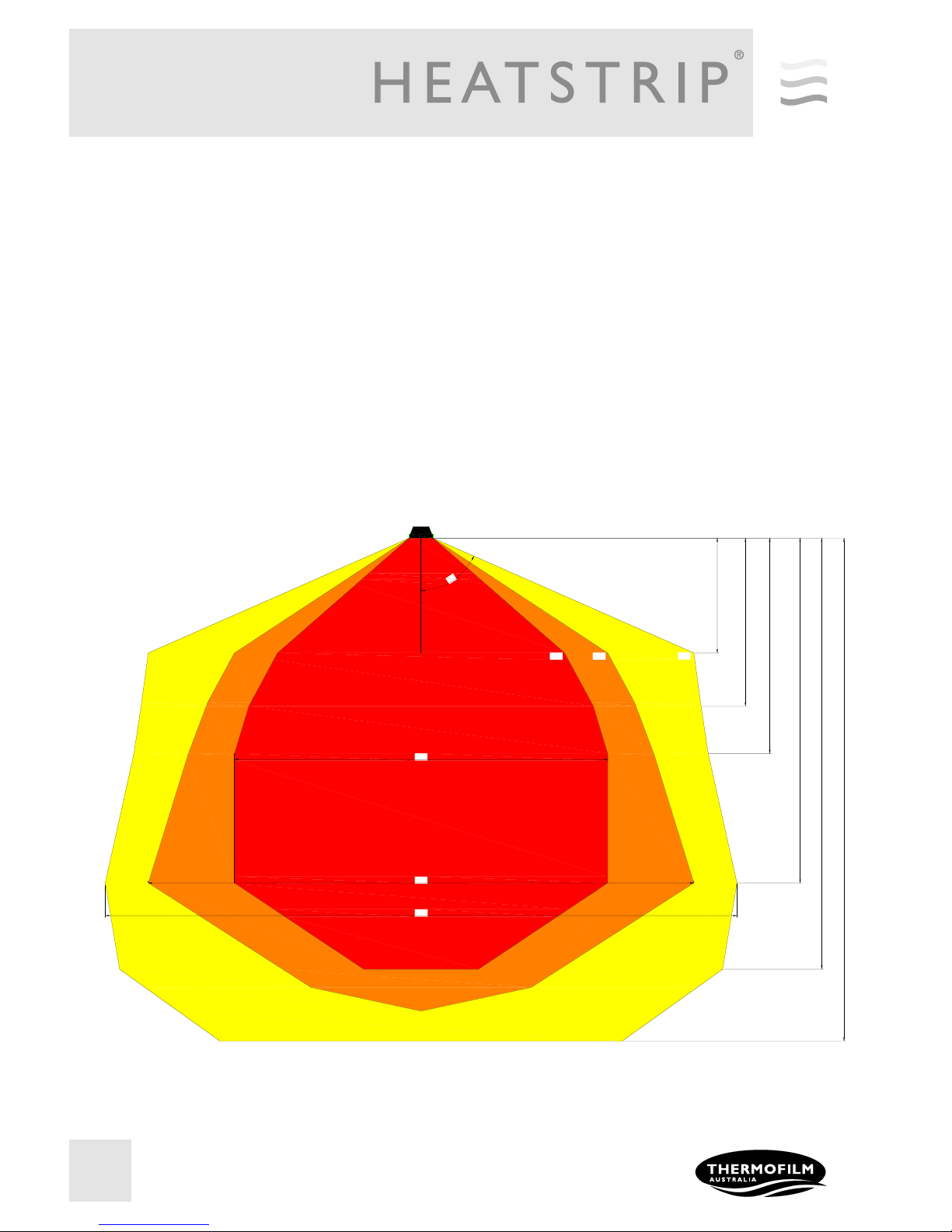
Radiant footprint
HEATSTRIP® electric heater produce radiant heat, which heats objects rather than the air. Therefore, it is imperative that
objects to be heated (ie. People), are within the direct radiant footprint of the heater.
The diagram below shows the radiant footprint of HEATSTRIP® Max, and is an approximate guide based on a fully
enclosed, outdoor environment.
This diagram shows that the maximum heat output is found directly under the heater, and the temperature decreases as
you move away from the heater.
It highlights the importance of maintaining recommended mounting heights, and positioning the heater directly above the
area to be heated, if possible.
Also, the temperature (ie. surface temperature) is the same for both models, regardless of the wattage. However, the size
increases and the length of the unit increases, the radiant footprint will be larger.
800mm STANDING HEIGHT
1170mm SITTING HEIGHT
2400
1500
25°C
21°C
66°
23°C
2600
3800
4400
THX RADIANT CROSS SECTIONAL AREA
3000
3500mm MAXIMUM HEIGHT
Page 7
7
Selection guide
Prior to selecting the exact model and quantity required for your application, please ensure the correct range of Heatstrip
heaters is being used.
Below is an overview of the Heatstrip options.
HEATSTRIP® Classic (THH models) is a premium high temperature heater and is primarily used for outdoor rooms
where there is 1,2 3 or 4 enclosed sides, with an ideal mounting height of 2.1 m to 2.7m. Ideal for hard to heat indoor applications or moist environments where an IP55 rating is required.
HEATSTRIP® Max (THX models) is an ultra high temperature heater used for uncovered or open areas with a
mounting height of 2.4 m to 3.5m. Also suitable for difficult indoor environments such as showrooms, production lines,
warehouses etc.
HEATSTRIP® Indoor (THS models) is a medium intensity heater used for protected indoor applications, such as
sunrooms, school classrooms, halls, gymnasiums etc.
General recommendations for HEATSTRIP® Max:
Ideal mounting height: 2.4m to 3.5m. Maximum is 3.5m in a protected outdoor environment.
Ideal mounting location: ceiling mounted, directly above area to be heated (eg. above a table)
Based on the radiant footprint of the previous page, for a protected outdoor area, a minimum of 250W/m2 is re-
quired. For indoor spot heating, a minimum heating capacity of 150W/m2 is recommended.
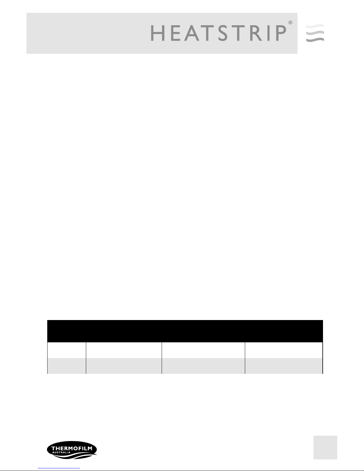
The below table outlines the coverage of each HEATSTRIP
®
Max model (in m2), based on 3 different scenarios.
For example, for an outdoor area that is protected from prevailing winds by walls, café blinds etc, Model THX2400 will
cover 9.5m2 and Model THX3600 will cover 14.5m2.
MODEL INDOOR PROTECTED (m2) OUTDOOR ENCLOSED (m2) OUTDOOR EXPOSED (m2)
THX2400 16 9.5 6
THX3600 24 14.5 9
Page 8
8
Installation Requirements
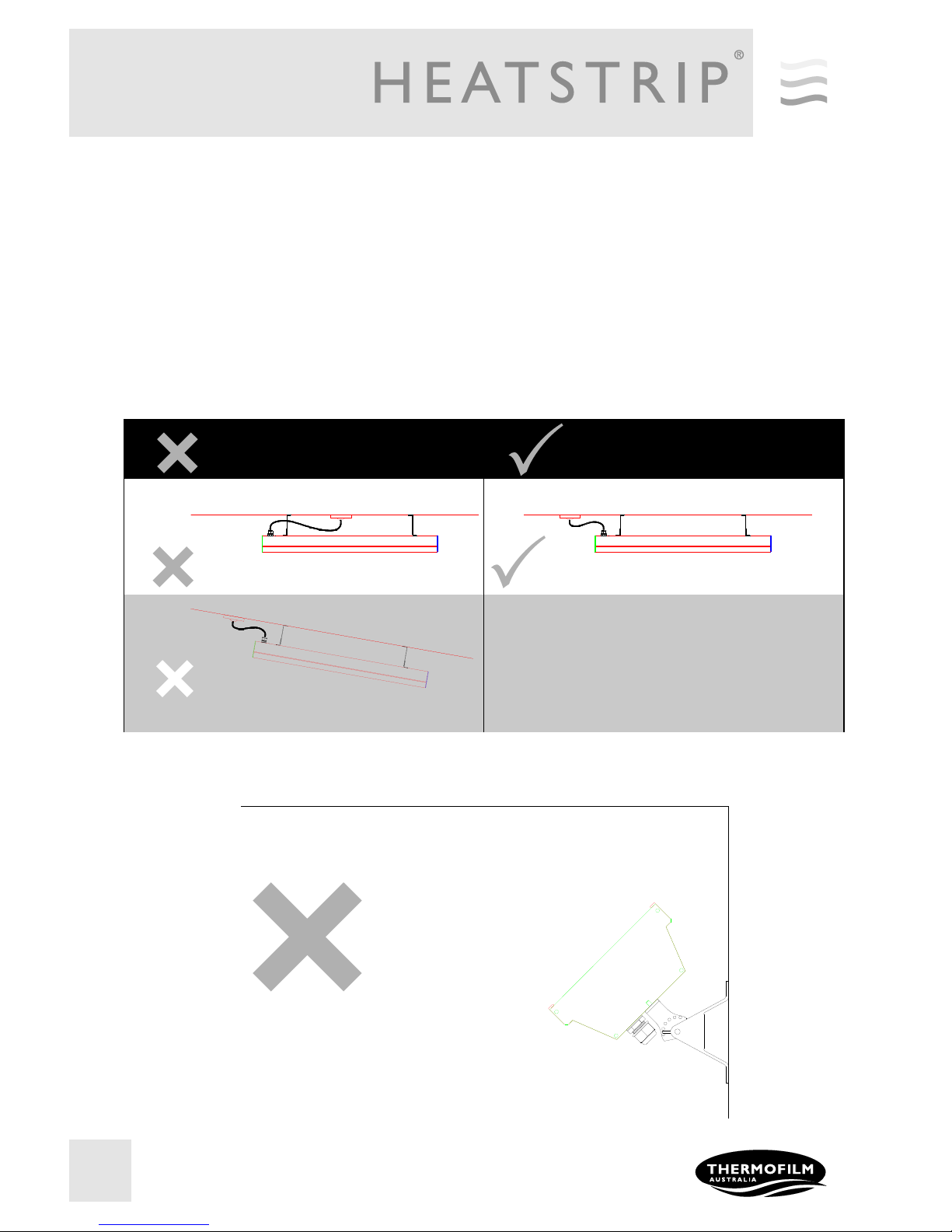
The ideal mounting position for the HEATSTRIP®. Max is on the ceiling, directly above the area to be heated. If this is not
possible, HEATSTRIP®. Max can be mounted on a wall and angled downwards. In this situation, ensure the mounting
height is in the range of 2.4m to 3.0m and the table is within 3.0m of the wall.
For mounting heights more than 3.5m, we recommend the use of the optional accessories to reduce the height of the
heater to 2.4m-3.5 m. This will increase the effectiveness of your HEATSTRIP
®.
Refer to the Mounting Accessory section
for more information.
Electrical connections/GPO’s should not be located at the back of the heater. They should be located outside the physical
footprint of the units to minimize heat build-up behind the units.
Incorrect Installation Correct Installation
The heating surface must never be directed toward the ceiling
CEILING
CEILING
CEILING
CEILING
Page 9
9
LIGHT OR SPRINKLER MUST
NOT BE BELOW THE HEATER
CEILING
FLOOR
SURFACE BELOW HEATER
150mm MIN.
300mm MIN.
1000mm MIN.
150mm MIN.
2100mm MIN.
LIGHT OR SPRINKLER MUST
NOT BE BELOW THE HEATER
CEILING
FLOOR
SURFACE BELOW HEATER
300mm MIN.
150mm MIN.
150mm MIN.
2100mm MIN.
1000mm MIN.
Angled Ceiling Installation
Ceiling Installation
150mm MIN.
150mm MIN.
300mm MIN.
LIGHT OR SPRINKLER MUST
NOT BE BELOW THE HEATER
CEILING
FLOOR
SURFACE BELOW HEATER
1000mm MIN.
2100mm MIN.
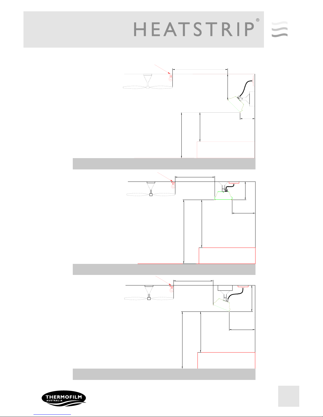
Installation location —the below diagrams confirm the minimum recommended clearances.
Angled Wall Installation
Page 10
10
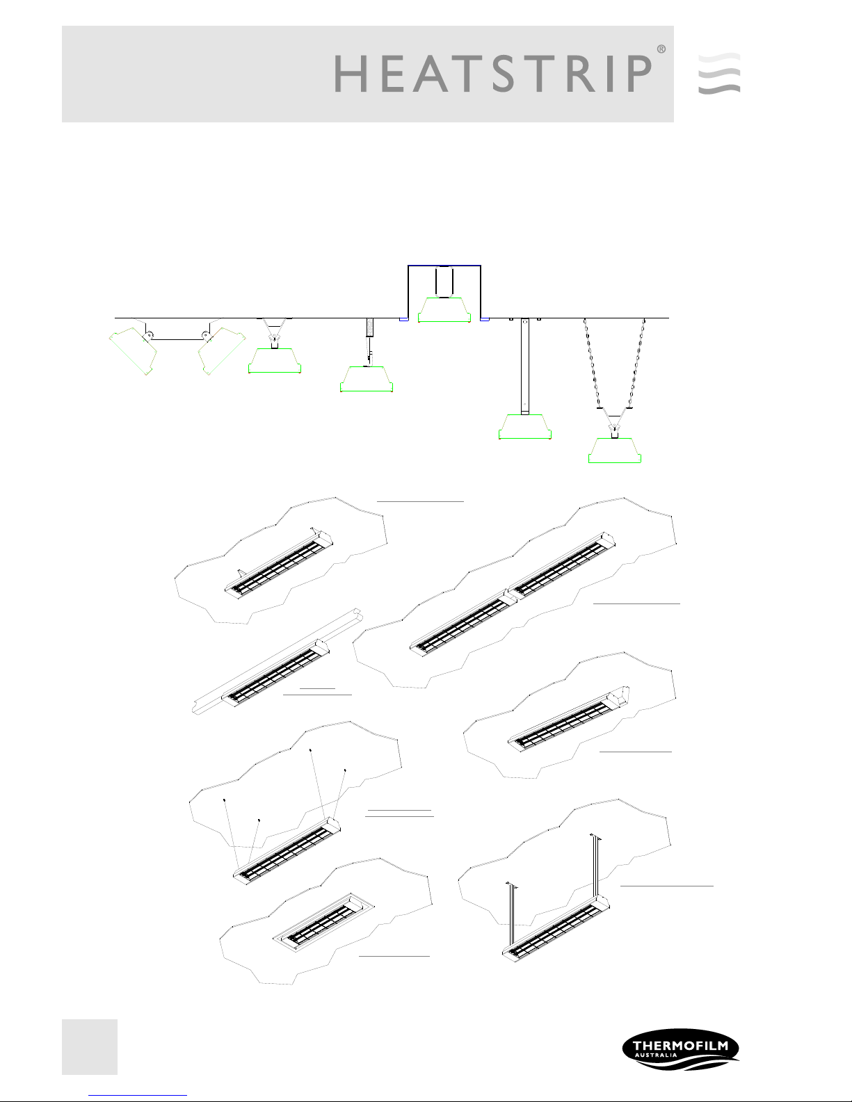
Mounting options
The installation of HEATSTRIP® Max is simple and easy with the standard mounting brackets supplied. For other more
challenging locations there are a range of mounting options available - refer to below diagrams.
The HEATSTRIP® Max can be mounted directly to the ceiling, angled downwards on a wall, suspended on chains or
poles; attached to beams or poles; or 2 units together. Refer to the following pages for more detailed information on each
mounting option.
STANDARD MOUNTING BRACKETS
INCLUDED IN BOX
BEAM MOUNT
WITH STANDARD BRACKET
END TO END MOUNTING BRACKET
SUSPENSION MOUNTING
WITH STANDARD BRACKET
EXTENSION MOUNT KIT WITH POLES
TWIN MOUNTING BRACKETS
FLUSH MOUNT ENCLOSURE
CEILING
TWIN MOUNT
BRACKET
STANDARD
BRACKET
EXTENSION MOUNT
BRACKET
SUSPENSION MOUNT USING
STANDARD BRACKET
BEAM MOUNT USING
STANDARD BRACKET
FLUSH MOUNT
ENCLOSURE
Page 11
11
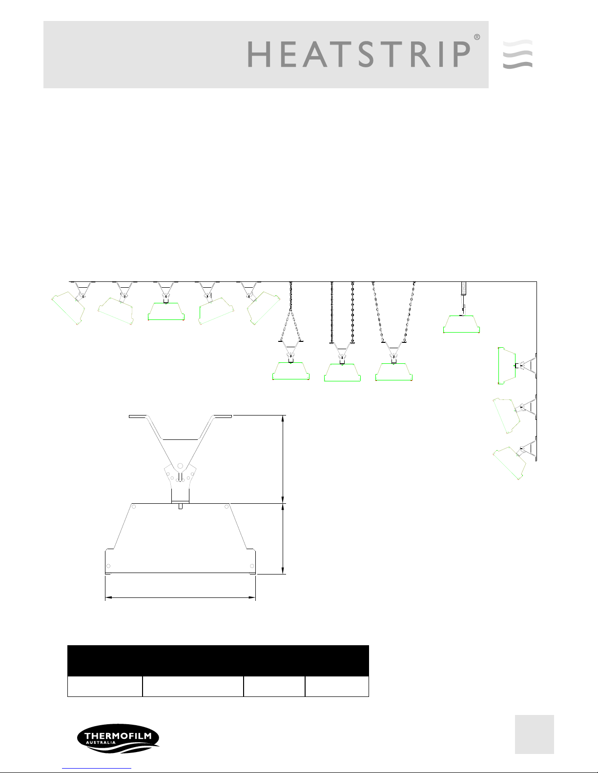
Standard mounting brackets
The HEATSTRIP® Max comes with a pair of standard mounting brackets. These adjustable brackets allow direct ceiling or
wall mount, and come with preset angle options of parallel, 22.5° and 45°.
The flexible standard mounting bracket can be turned 90 degrees to mount onto a beam, it can also be used to suspend
with chains.
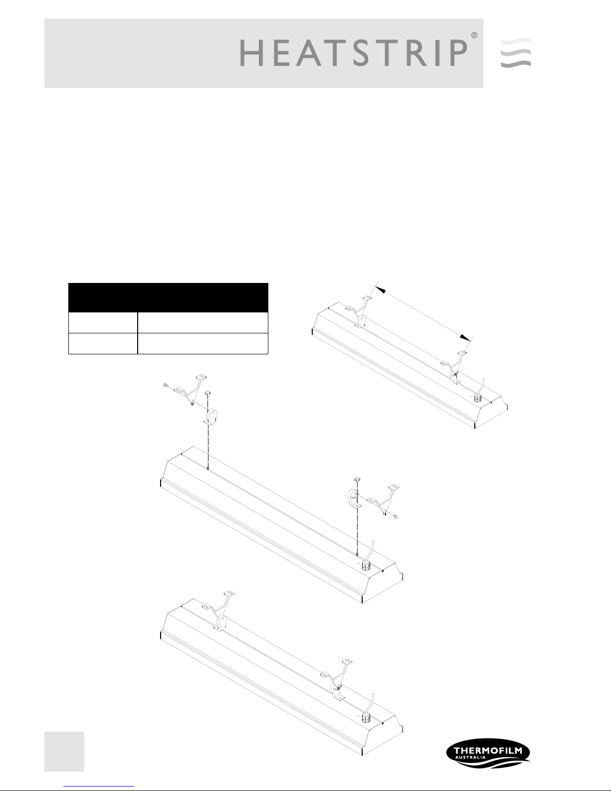
The brackets need to be mounted onto a secure frame or wall with a minimum distance between the two brackets. The
minimum distance (“B”) for each model is listed in the table below.
When completing the installation, ensure all screws are tight and unit is secure.
Note: When suspension mounting, chains are not included.
PART No PACKAGED
DIMENSIONS (mm)
WEIGHT (kg) MATERIALS
ZBRAK-104 125 x 100 x 40 0.2 ALLOY
Standard Mounting Bracket
100
80
170
CEILING
CEILING MOUNTING
BEAM MOUNTING
SUSPENSION MOUNTING
WALL MOUNTING
Page 12
12
MODEL “B”
MINIMUM DISTANCE (mm)
THX2400 400
THX3600 600
MOUNTING
Fix the two mounting brackets to the ceiling or wall in the desired location (refer minimum bracket centre chart).
Make sure the method of fixing (bolts or screws) will be more than strong enough to support weight of heater
allowing for strong winds and other conditions.
Fix the L brackets to the threaded connectors in the required locations on rear of heater to match the centres of
the mounting brackets.
Lift heater into position and secure the mounting brackets to the L brackets using the screws provided.
Locate the C cutout on the L bracket onto the stud in the mounting bracket so you achieve either horizontal or
angle mounting position as required.
Tighten all screws/bolts/nuts.
NOTE: the standard bracket allows for normal or angle mounting of the heater and is suitable for ceiling or wall
mounting.
"B"
Page 13
13
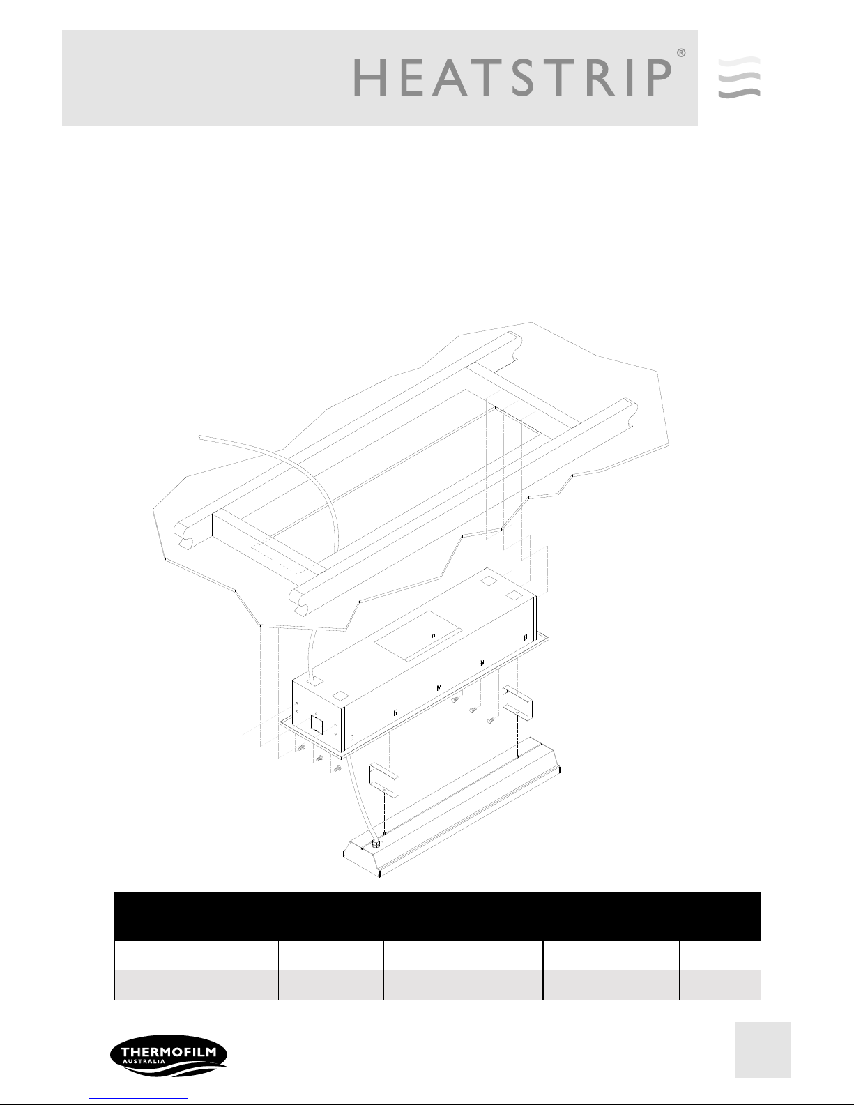
FLUSH MOUNT ENCLOSURE
The Flush Mount Enclosure is an ideal way to neatly install the HEATSTRIP® MAX into a ceiling. They are available for all HEATSTRIP® MAX models, and are supplied as a one piece unit for mounting of heaters. Flush
mounting can be used with plaster or wood lined ceiling materials.
An ideal mounting height is 2.4m-3.0m, with a maximum ceiling height of 3.5m in an outdoor environment. Maximum mounting heights should be strictly followed, otherwise the performance of the units may be reduced.
The facia of the enclosure is manufactured from 316 Stainless Steel and the rear casing is black zinc coated
steel.
Please refer to the Installation Manual for more detailed installation information.
SUITABLE FOR
MODELS
PART No HOLE CUTOUT
DIMENSIONS (mm)
OVERALL
DIMENSIONS (mm)
WEIGHT
(kg)
THX2400
THXAC-030 935 x 250 980 x 180 x 290 5
THX3600 THXAC-031 1260 x 250 1310 x 180 x 290 6
Page 14
14
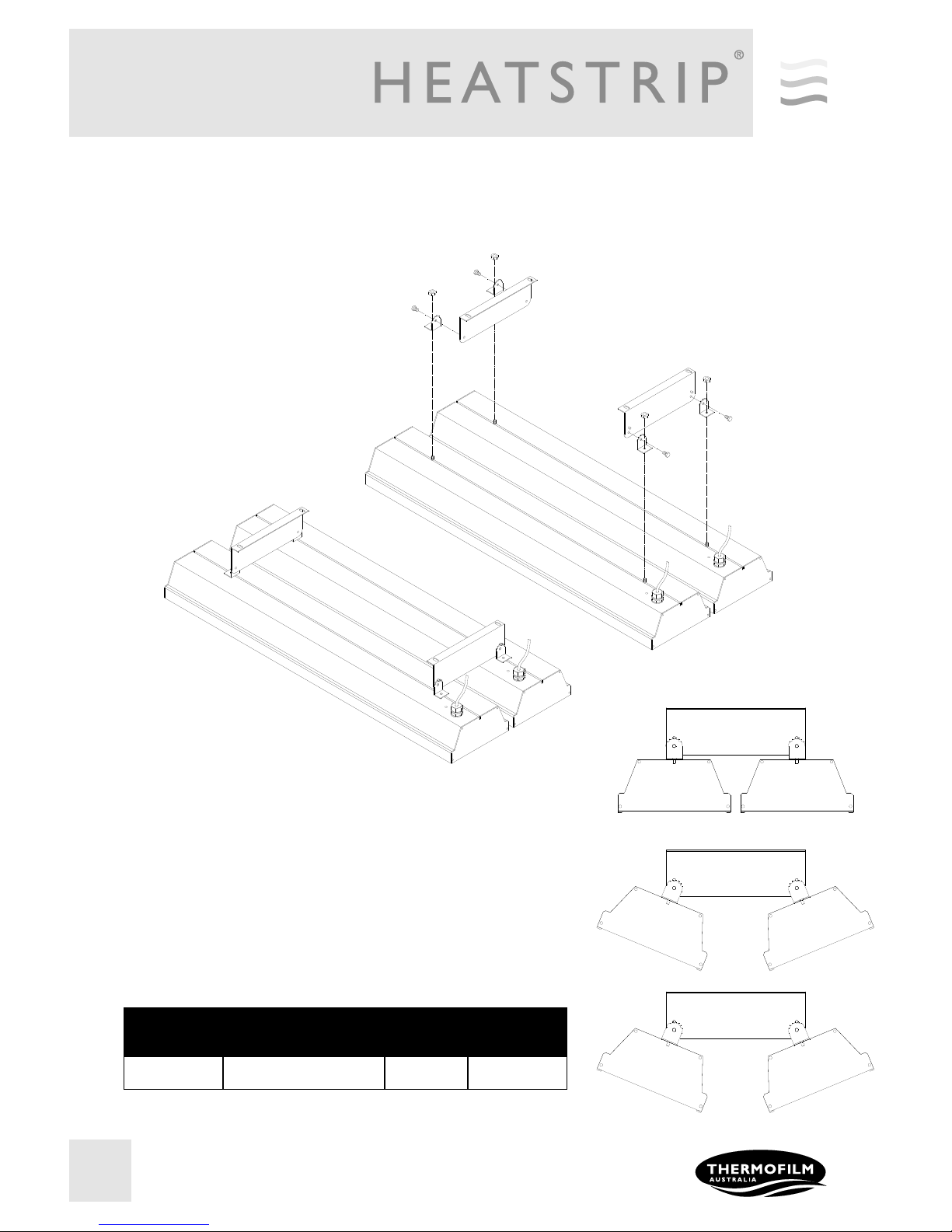
Twin mounting bracket
PART No PACKAGED
DIMENSIONS (mm)
WEIGHT
(kg)
MATERIALS
THXAC-018 220 x 100 x 25 1 316 SS
The optional Twin Mount bracket allows for two (2) units of HEATSTRIP
Max to be mounted side-by-side, either in parallel or angled as per the
diagram on the right. This is ideal for applications when a wider heat
coverage is required, or when there is mounting restrictions/limitations
(such as running between 2 rows of tables etc.)
Page 15
15
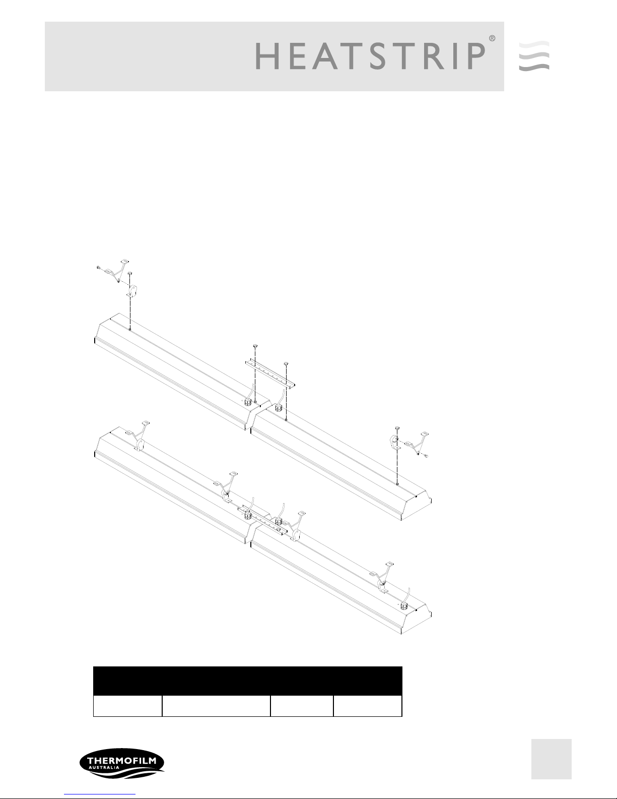
End to end mounting bracket
PART No PACKAGAED
DIMENSIONS (mm)
WEIGHT
(kg)
MATERIALS
THXAC-019 260 x 50 x 50 0.5 316 SS
The end to end bracket allows multiple units to be joined in a straight line for maximum heat performance
and aesthetic appeal. This is ideal for applications such as long rows of tables and assembly lines, where a
constant heat coverage is required.
The bracket allows for a 50mm gap between units and an opening for the power connection. As per the diagram below, units should be mounted with the power leads together.
The end to end bracket can be used with either the standard ceiling/wall mount bracket or the extension
bracket & pole kit.
Page 16
16
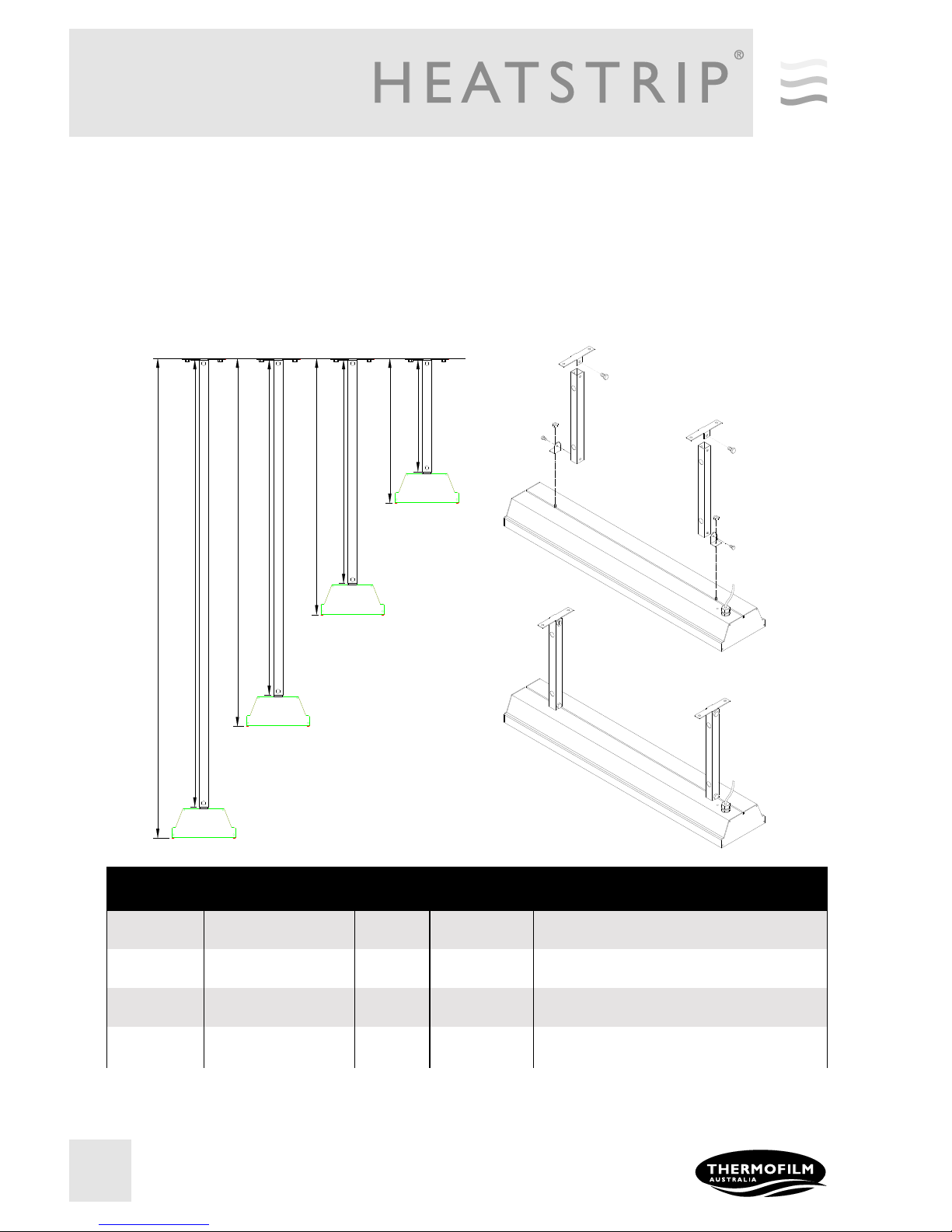
Extension Mount Bracket
PART No PACKAGED
DIMENSIONS (mm)
WEIGHT
(kg)
MATERIALS NOTES
THHAC-005 300 x 150 x 50 2 316 SS Kit includes 2x300mm extension pole, screws
and brackets
THHAC-006 600 x 150 x 50 2 316 SS Kit includes 2x600mm extension pole, screws
and brackets
THHAC-007 900 x 150 x 50 2.5 316 SS Kit includes 2x900mm extension pole, screws
and brackets
THHAC-008 1200 x 150 x 50 3 316 SS Kit includes 2x1200mm extension pole, screws
and brackets
The Extension Mount bracket allows HEATSTRIP® Max units to be lowered from high ceilings, using rigid connections. The brackets are for use with 25mm x 25mm x 1mm tube (SHS), supplied as a complete kit with
brackets, pre-cut poles and connections. The standard length options as part of the kit are 300mm, 600mm,
900mm and 1200mm.
The kits include all brackets, poles and screws necessary for connection to the heaters, however it does not
include screws for attachment to the ceiling.
300
600
388
900
1200
688
988
1288
Page 17
17
Safety
HEATSTRIP® Max has an IP rating of X5. This means it is safe for water ingress from all directions. The HEATSTRIP®
can be safely hosed down.
HEATSTRIP® has undergone extensive testing both in laboratory conditions; in Thermofilm’s manufacturing facility in
Melbourne and field trials in Australia and overseas. It has been this testing that gives the purchaser the confidence of a
high quality product.
Independent laboratory testing has confirmed Thermofilm’s full compliance with Australian and other International
Standards. This includes CE, AS/ANZ, UL/CSE
The heater comes in both plug (2400W) and hardwired (3600W) versions. In both cases the fixed wiring must be installed
by a licensed electrician in accordance with the relevant wiring regulations.
HEATSTRIP® is Class 1 equipment and must be earthed.
In operation, this heater is VERY HOT— do not touch any part of the heater while it is turned on. Do not touch any part
until 30 minutes after it is turned off.
This appliance is not intended for use by persons (including children) with reduced physical, sensory or intellectual
capabilities, or lack of experience and knowledge, unless they have been given supervision or instruction concerning use
of the appliance by a person responsible for their safety. Children should be supervised to ensure they do not play with the
appliance.
Do not allow any cables, furnishings, flammable materials or other items come in contact with any surface of the heater.
If installed in wet areas, the heater switches or controls must be located so that they cannot be touched by persons in the
bath or shower.
The heater needs to be installed as per the installation instructions paying special attention to the minimum clearances.
The heater needs to be mounted on a rigid bracket or fixing.
The heater must not be mounted immediately below or in front of a socket outlet.
In case of a heater fault or damaged supply lead, the appliance should be returned to the point of purchase for return to
Thermofilm for repair.
Maintenance
The HEATSTRIP® is made from durable materials, however regular care and maintenance of your heater will help prolong
the life of the heater.
It is recommended that you hose down the heater and with a soft cloth gently wipe the surfaces of the heater with a mild
detergent to remove the built up contaminants from the environment. Then rinse all detergent off the heater.
All chemicals in the atmosphere including cigarette smoke, pollution etc. will tarnish the surface of the heater. In this case,
additional cleaning and maintenance may be required. The cleaning process at least every three months will reduce the
amount of build up and keep it looking as best it can. If the heater is in a corrosive environment eg. salt spray, we
recommend that you clean your heater with a light spray of fresh water every week. After cleaning, turn the heater on for
20 minutes to dry any water residue and prevent water staining.
Before cleaning or inspection activity, the heater must be switched off and cooled down completely.
Do not use any abrasive materials or products to clean the heater, this includes solvents, citrus based cleaners or other
harsh cleaning products.
When handling the heater, ensure that your hands are clean or that you use clean gloves as grease or dirt can mark the
surface of the heater.
Do not use high pressure water to clean heaters, light water spray only.
Page 18
18
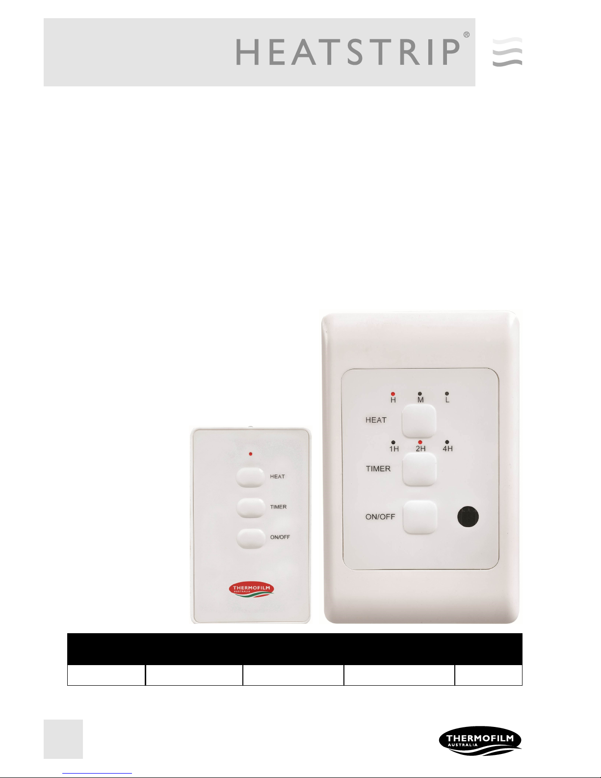
HEATSTRIP® Wall Controller
MODEL MAXIMUM
VOLTAGE (Volts)
MAXIMUM
CURRENT (Amps)
PACKAGED
DIMENSIONS (mm)
WEIGHT (kg)
TT-MTM2 240 16 150 x 95 x 55 0.3
TT-MTM2 Wall Controller
This controller is a custom designed and manufactured controller for HEATSTRIP® heaters. It has been designed for
ease of use and to provide low running costs of your heater. It provides both temperature control (allowing the user to
turn the heat output up or down depending on the ambient temperature and conditions) and a timer for automatic
heater shut-off operation.
The timer function has four settings: 1 hour, 2 hours, 4 hours or constantly on. This feature is ideal for applications
such as BBQ, alfresco areas, restaurant dining, assembly line production etc. when continuous heat is not required.
The timer also reduces the likelihood of heaters being inadvertently left turned on.
Depending on the ambient temperature there may be a requirement to control the heat output of the heater. The
controller has 3 settings, they are High, Medium and Low.
The controller allows a combination of the multiple timer (1/2/4 hour) and heat outputs (High/Medium/Low).
The controller comes with a remote control unit which provides
convenient control of the heater power output and timer functions.
Controlling multiple heaters
It is possible to use one wall controller to control multiple heaters.
The wall controller is rated at 16 Amps and 240 volts. For a larger
current draw, talk to your electrician who can use a relay to
connect more units.
Remote pairing
All units operate using the
same remote control
frequency, therefore, multiple
wall controllers can be
operated using a single remote
control.
The remote will function at
distances of over 8m when
used in a straight line. This
distance reduces when used at
an angle.
Page 19
19
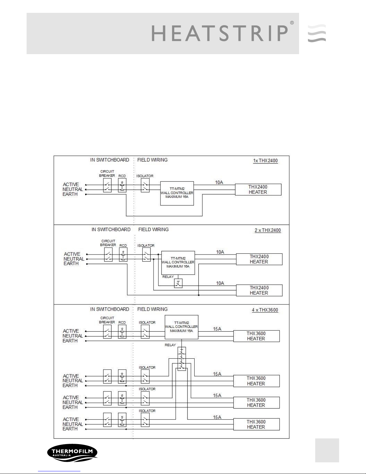
Heater wiring schematic diagrams
It is recommended to install an ON/OFF isolation switch before the controller and ensure the unit is turned OFF after use.
As the minimum current rating for THX is 10Amps (THX2400), only 1 heater can be directly wired to the controller.
When more heating units need to be connected from the same controller a relay will be required. It is recommended that
you talk to your electrician for more detail.
Below are example circuits indicating potential installation configurations.
Always check with your electrician and ensure all wiring is in accordance with local regulations.
Note to electrician: The controller modulates the heat output using a “timed on / timed off” function. The controller does not
modulate the voltage output. A relay is therefore suitable for this application.
Page 20
20
Warranty Terms & Conditions
The below Warranty Terms and Conditions apply for New Zealand and Australia only. For international warranty please refer
to international warranty terms and conditions.
Thermofilm warrants to the original owner that HEATSTRIP® Max products will be free from defects in materials and
workmanship for a period of 24 months from the date of purchase in accordance with the following warranty terms and
conditions.
Provision of this warranty is subject to:
The HEATSTRIP
®
product must be installed in accordance with the Installation Instructions and relevant electrical
standards and codes.
The HEATSTRIP
®
product must be maintained and cleaned according to instructions detailed in the Installation Manual.
There is no warranty expressed or implied with regard to capacity requirements. The selection of the unit or units
depends entirely upon the system design and capacities as determined by the purchaser.
The customer has not repaired, opened or altered the product in any unauthorised manner.
This warranty excludes damage to the product or components arising from circumstances outside the control of
Thermofilm, including, but not limited to, where the product is not used for intended purpose; where the product has
been rectified in any way; incorrect installation; incorrect power supply; damaged caused during delivery; misapplication,
misuse, abuse, vandalism, lack of maintenance or accident.
Thermofilm’s obligations under this warranty are limited to repair or replacement at Thermofilm’s factory of any
components of the product which Thermofilm identifies to its satisfaction to be defective.
Transportation charges involved in return of the product to the Thermofilm factory (or any other location authorised in
writing by Thermofilm) is the sole responsibility of the customer.
All products are inspected and tested before despatch and are at the risk of the purchaser after the shipment from the
Thermofilm factory, if not delivered by Thermofilm to destination.
Discolouration of the surface may occur after a period of time, this does not constitute a warrantable event.
Twisting and bending of the heaters may occur, this does not constitute a warrantable event.
No products or components will be supplied in advance of an examination of the faulty product or components by
Thermofilm or an authorized representative of Thermofilm.
Thermofilm does not participate in any site related costs or labour expenses incidental to replacement of parts, repairing,
removing, installing, servicing, transportation or handling of parts to complete products, and assumes no liability on parts
repaired or replaced without written authorisation. Thermofilm shall not be liable for any default or delay in performance
of its warranty obligations caused by any circumstances beyond its control, including, but not limited to, judicial or
government restrictions, strikes, fires, floods, abnormal weather conditions, delayed supply of components.
Should products be determined as damaged on arrival, immediately notify the transport company of the condition and have
them noted on the freight documents. If damage is discovered after unpacking, demand immediate inspection by the
transportation company and insist that a record of the damage is made on the freight documentation.
The customer warrants using the product in accordance with:
Any instructions provided to it by Thermofilm from time to time.
All government and local regulations, including but not limited to all relevant electrical, environmental laws and
regulations governing the installation, storage, use, handling and maintenance of the goods.
All necessary and appropriate precautions and safety measures relating to the installation, storage, use, handling and
maintenance of goods.
Our goods come with guarantees that cannot be excluded under the Australian Consumer Law. You are entitled to a
replacement or refund for a major failure and for compensation for any other reasonably foreseeable loss or damage.
You are also entitled to have the goods repaired or replaced if the goods fail to be of acceptable quality and the failure
does not amount to a major failure.
All warranty requests for repairs or replacements must be accompanied by a complete “Warranty Claim Form” available
from Thermofilm, together with proof of purchase (and where possible, photos of the installation) and the heater returned
to the place of purchase.
In the event of a warranty claim, the goods need to be returned to the distributor/retailer for repair/replacement. Contact
Thermofilm Australia Pty Ltd
17 Johnston Court, Dandenong South, Victoria 3175, Australia
Telephone: (03) 9562 3455, Fax: (03) 9548 3979
Email: [email protected]
www.thermofilm.com.au
 Loading...