

HEATSTRIP THH 1500, THH 2400, THH 3200, THH 1500SS, THH 2400SS Installation, Operation & Maintenance Manual
...
Models Watts Dimensions Ratings
THH 1500, THH 1500SS 1550 850 x 170 x 40mm 230V 50Hz a.c
THH 2400, THH 2400SS 2500 1330 x 170 x 40mm 230V 50Hz a.c
THH 3200, THH 3200SS 3350 1770 x 170 x 40mm 230V 50Hz a.c
Note: THH series HEATSTRIPS have an IPX5 rating for protection against water ingress. Prior to
installing and operating the heater, read these instructions carefully and retain for future reference.
Preparation
The THH Series HEATSTRIPS are high intensity Radiant Strip Heaters designed for Domestic / 1.
Commercial heating applications within indoor or outdoor undercover areas, and should not be
used for any other purpose.
Before commencing installation, make sure the electrical supply voltage is the same as that 2.
shown on the rating plate of the heater.
The heater is fi tted with a length of fl exible cable for electrical connection. The heater should 3.
be connected as a fi xed installation by a licensed electrical person, according to the relevant
electrical standards.
All pole disconnection from the supply mains must be provided in fi xed wiring in accordance with 4.
the wiring rules.
This appliance must be earthed.5.
The heater is required to be fi tted with an “ON/OFF isolation switch and can also be controlled 6.
via thermostat, timer or dimmer type control. A wall switch should be installed on fi xed wire
installations. Optional connection to a R.C.D is recommended.
If the heater or supply lead is damaged, the appliance must be returned to the distributor / 7.
manufacturer for repair.
Installation Location
For both wall and ceiling mounting, the lowest part of the heater must be located a minimum of *
2100mm above fl oor level.
The heater must not be closer than 300mm to adjacent walls, with a minimum of 60mm *
between back of heater and any surface.
Allow 1000mm from the bottom of the heater to any surface below. *
Do not allow thermal insulation, cables, fl ammable materials or any other items to come into *
contact with any surface of the heater; purpose design brackets excluded.
The heater must not be located immediately below a socket outlet.*
If installed in wet areas, the heater must be installed so that switches and other controls cannot *
be touched by persons in the bath or shower.
Electric Radiant Outdoor Heater
Installation, Operation & Maintenance Manual
EUROPE / UNITED KINGDOM - ENGLISH
ENGLISH 1
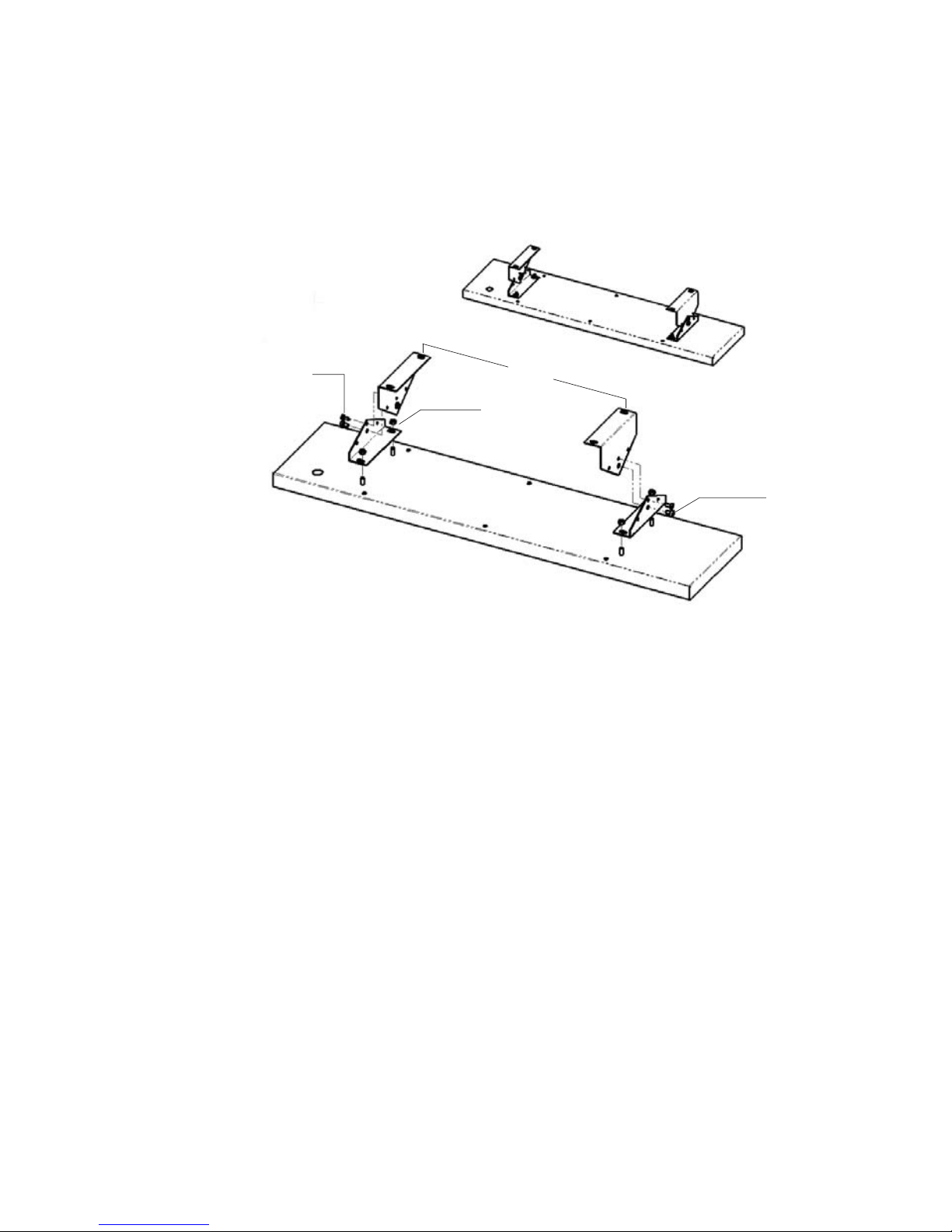
Self Tapping Screw
M5 Machine
Thread Screw
Dim “A”
M5 Hex Nut
Mounting Instructions
Using the centre distances shown in DIM “A”, mount the brackets to the ceiling or wall. *
Ensure fi xing method will adequately support weight of heater. *
Then, fi x brackets to heater using the nuts provided on the studs at rear of heater. *
Ensure screw fi xing two halves of bracket is fully tightened. *
Use the two small self tapping screws to lock the two halves of the bracket at the desired angle.*
The heating surface must never be directed toward the ceiling.*
The power cable must be at the lower end of the heater if the heater is installed at an angle.*
Operation Instructions
[To be kept by the user of this appliance]
The heater is required to be fi tted with an “ON/OFF” isolation switch and can also be controlled via
thermostat, timer or dimmer type control. Once the unit is turned On via a switch or other control
device, it will take approximately 10 minutes to warm up to normal operating temperature. Make
sure the unit is turned OFF after use.
Note: THH series HEATSTRIPS have an IPX5 rating for protection against water ingress.
CAUTION
The front panel of the heater can reach temperatures of up to 380°c.*
Do not touch any part of the heater while in operation or for 30 minutes after turning off.*
This appliance is not intended for use by young children or infi rm persons. *
Caution must be exercised when operating this appliance.*
Do not allow any cables, furnishings, fl ammable materials or other items to come into contact *
with any surface of the heater.
The heater must have a minimum 300mm clearance to adjacent walls and minimum 60mm *
clearance from the back of the heater to any mounted surface.
Do not operate heater unless there is a clearance of 1000mm or more from bottom of the heater *
to any surface below.
The heater should be connected as a fi xed installation by a licensed electrical person, according *
to the relevant electrical standards.
All pole disconnection from the supply mains must be provided in fi xed wiring in accordance with *
the wiring rules.
Model DIM “A”
THH 1500 300mm
THH 2400 600mm
THH 3200 900mm
ENGLISH 2
 Loading...