

Heatstore Multiflow 9.5kW, Multiflow 10.8kW, Multiflow 12.0kW Installation And User Manual
IMPORTANT:
This booklet should be left with the user after
installation and demonstration.
It should be kept in a safe place, as you may need to
refer to it for general instructions or future
maintenance
HEATSTORE MULTIFLOW
UNVENTED INSTANTANEOUS
WATER HEATER
Installation and User Guide
2
CONTENTS
If you experience any difficulty with the installation or operation of your new
water heater, then please refer to the “What to do if things go wrong” section
in this manual before contacting us.
INTRODUCTION
THIS APPLIANCE CAN BE USED BY CHILDREN AGED FROM 8 YEARS AND ABOVE AND
PERSONS WITH REDUCED PHYSICAL, SENSORY OR MENTAL CAPABILITIES,
OR LACK OF EXPERIENCE AND KNOWLEDGE IF THEY HAVE BEEN GIVEN SUPERVISION
OR INSTRUCTION CONCERNING USE OF THE APPLIANCE IN A SAFE WAY
AND UNDERSTAND THE HAZARDS INVOLVED.
CHILDREN SHALL NOT PLAY WITH THE APPLIANCE.
CLEANING AND USER MAINTENANCE SHALL NOT BE MADE BY CHILDREN.
Thank you for purchasing a quality
Heatstore Multiflow
manufactured in England.
To enjoy your new unit at its best, please take time to read this manual thoroughly to
familiarise yourself with all instructions, BEFORE beginning installation.
Your
Multiflow
has been designed for convenience, economy and safety of use, provided that it is
installed, used and maintained in good working order and in accordance with our instructions and
recommendations.
All wiring and installation must be supervised by a suitably qualified person.
THIS APPLIANCE MUST BE EARTHED.
The installation must be in accordance with the current edition of BS.7671 (
the “IEE Wiring
Regulations”)
and “Part P” of the
“Building Regulations”
in force at the time of installation.
Installations outside England and Wales must also conform to any local regulations in effect.
This appliance is intended to be permanently connected to the fixed electrical wiring of the mains
supply with its own dedicated supply.
Ensure that the mains water supply meets the requirements listed.
This appliance must NOT be fitted where it may be subjected to freezing conditions
DO NOT switch the appliance on if you suspect it of being frozen. Wait until it has thawed out.
The unit MUST NOT be mounted upside down (diagram 1b).
The unit MUST NOT be fitted to any type of THERMOSTATIC mixer valve or tap.
If a non-return valve is fitted in the Inlet feed to the unit, then the installation should also include
a 3.5 BAR Pressure Reducing Valve and a 6 BAR Pressure Relief (Expansion) Valve.
Isolate the mains electrical and water supply before removing appliance front cover.
Section
Introduction . . . . . . . . . . . . . . . . . . . . . . . . . . . . . . . . . . . . . . . . . . . . . . . . . . . . . . . .
Important Safety Information . . . . . . . . . . . . . . . . . . . . . . . . . . . . . . . . . . . . . . . . . . . .
How to install your
Multiflow
. . . . . . . . . . . . . . . . . . . . . . . . . . . . . . . . . . . . . . . . . . . .
Commissioning your
Multiflow
. . . . . . . . . . . . . . . . . . . . . . . . . . . . . . . . . . . . . . . . . . .
How to use your
Multiflow
. . . . . . . . . . . . . . . . . . . . . . . . . . . . . . . . . . . . . . . . . . . . .
What to do if things go wrong (1) Self Help . . . . . . . . . . . . . . . . . . . . . . . . . . . . . . . . . .
Heatstore After Sales Service . . . . . . . . . . . . . . . . . . . . . . . . . . . . . . . . . . . . . . . . . . . .
Additional Accessories and Common Spare Parts . . . . . . . . . . . . . . . . . . . . . . . . . . . . . .
What to do if things go wrong (2) Professional Service . . . . . . . . . . . . . . . . . . . . . . . . . .
How your
Multiflow
Works . . . . . . . . . . . . . . . . . . . . . . . . . . . . . . . . . . . . . . . . . . . . . .
Guarantee and Contact Details . . . . . . . . . . . . . . . . . . . . . . . . . . . . . . . . . . . . . . . . . . .
Page
2
2
3
7
8
9
9
9
10
11
12
IMPORTANT SAFETY INFORMATION

3
WARNING: ALL WIRING AND INSTALLATION MUST BE SUPERVISED BY A SUITABLY
QUALIFIED PERSON.
WARNING: DO NOT INSTALL WHERE IT MAY BE SUBJECTED TO FREEZING CONDITIONS.
The Multiflow is recommended to supply a MAXIMUM of two washbasins (see diagram 1a)
OR a washbasin and shower (see diagram 4b)
If the Multiflow is connected to a mixer tap then only NON-Thermostatic types should be used
(water mixes at the outlet pipe only).
The Multiflow is NOT to be fitted to a bath or kitchen sink other than for hand-washing purposes.
(See Guarantee exclusions on page 12 and product flow rate tables on page 11).
The unit MUST NOT be mounted upside down (diagram 1b).
BEFORE YOU START
Check the unit rating plate to ensure the mains electric is capable of supplying the required current.
Check the pressure of the main water supply.
To operate correctly, the unit requires the following running pressures, check unit rating plate:-
Model
Dynamic Water Pressure
Basin
Shower
Minimum
Maximum
Minimum
Maximum
Up to
9.5kW
10 psi (0.7 bar)
(69 kPa)
150 psi (10.3 bar)
(1035 kPa)
15 psi (1.1 bar)
(103 kPa)
150 psi (10.3 bar)
(1035 kPa)
Up to
10.8kW
15 psi (1.1 bar)
(103 kPa)
150 psi (10.3 bar)
(1035 kPa)
20 psi (1.4 bar)
(138 kPa)
150 psi (10.3 bar)
(1035 kPa)
Up to
12.0kW
20 psi (1.4 bar)
(138 kPa)
150 psi (10.3 bar)
(1035 kPa)
25 psi (1.8 bar)
(172 kPa)
150 psi (10.3 bar)
(1035 kPa)
FIXING THE UNIT TO THE WALL
Deciding the position
If being used in a public place, position the unit out of reach to discourage vandalism.
Fit the unit onto a flat piece of wall, well away from any potential splashes of water or spray.
Position the unit either upright or lengthways (diagram 1a/b), whichever is most convenient for
plumbing and wiring, keeping the hot water pipe length to a minimum in order to save energy.
To maintain the integrity of the IPX4 Protection Rating,
the unit MUST NOT be mounted upside down (diagram 1b)
If the unit is to supply a basin, you can fit it either above or below the basin.
HOW TO INSTALL YOUR
MULTIFLOW
Diagram 1a
Examples of fitted units
Diagram 1b
Acceptable unit orientation
4
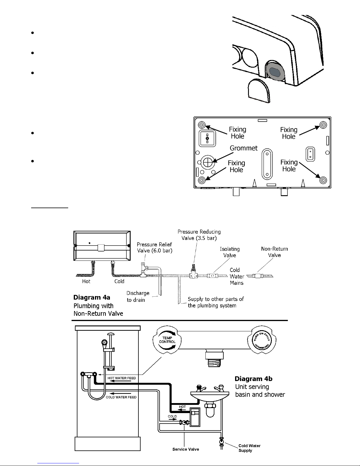
Deciding the wiring route
You have a choice of whether to feed the electric cable
through the side or through the back of the unit.
If it going through the side of the unit, cut out the plastic lug
to expose the grommet (diagram 2).
If is going through the back of the unit, cut through the
grommet on the backplate with a sharp knife (Take Care!).
Make sure you do not remove the grommet from the
backplate (diagram 3).
Feed the cable through the grommet before you fix the unit to the wall.
Fixing to the wall
Undo the retaining nuts and take the front cover
off the unit. Hold the backplate in position against
the wall whilst you mark the four fixing holes.
Drill the holes and fix the unit to the wall using
the screws supplied.
Plumbing the unit
WARNING: IF A NON RETURN VALVE IS FITTED IN THE INLET FEED TO THE UNIT,
THEN THE INSTALLATION SHOULD ALSO INCLUDE A 3.5 BAR PRESSURE
REDUCING VALVE AND A 6 BAR PRESSURE RELIEF (EXPANSION) VALVE
Diagram 2
Lug cut out
Diagram 3
Back of unit
 Loading...