

Heatstore HS30U, HS50U Installation And User Instructions Manual
MULTIPOINT 30/50
1
Installation and User Instructions
HS30U, HS50U
Please read and understand these instructions before starting work.
Please leave this leaflet with the user following installation
PACK CONTENTS
Heater, Factory fitted temperature and pressure relief valve,
Control pack, Fixing screws, Bracket,
Installation and user instructions
WARNING
This water heater must only be installed by qualified persons.
36005795 Issue 1.

2
Please read and understand these instructions prior to installing your Heatstore
unvented water heater. Particular attention should be paid to the section headed
IMPORTANT INSTALLATION POINTS. Following installation and commissioning
the operation of the heater should be explained to the customer and these instructions
left with them for future reference.
TECHNICAL SPECIFICATIONS
Electrical rating .................................................... 2.75/3kW 230/240V
Capacities............................................................. 30 or 50 litres
Weight (full) ......................................................... 30 litre - 42.5kg
............................................................................. 50 litre - 69.3kg
Rated pressure ..................................................... 6 bar
Minimum recommended supply pressure ............ 0.8 bar
Temperature/Pressure Relief Valve ....................... 90oC/7 bar
COMPONENT CHECK LIST
Before commencing installation check that all the following components have
been supplied in the Installation Kit.
l Expansion Vessel 3/4BSP male, precharge pressure 3.5 bar c/w wall mount
ing bracket
l Combined Pressure Reducing Valve/Strainer 1/2BSP female, factory set at 3.5
bar
l Single Check Valve 15mm x 15mm compression
l Pressure (expansion) Relief Valve 1/2BSP male inlet, 1/2BSP female
discharge, factory set at 6 bar
l Tundish 1/2BSP male inlet, 3/4BSP female outlet
l Wall mounting bracket set
l Self adhesive Levelling Feet (2 off)
l Moulded plastic Spacer
1.0 IMPORTANT INSTALLATION POINTS
1.1 This Heatstore unvented water heater is factory fitted with a Temperature/Pressure
Relief Valve. The factory fitted Temperature/Pressure Relief Valve must not be
removed, blocked or restricted in any way. FAILURE TO PROVIDE ADEQUATE
TEMPERATURE AND PRESSURE RELIEF WILL INVALIDATE ANY GUARANTEE AND LEAD TO A DANGEROUS INSTALLATION
MULTIPOINT 30/50
3
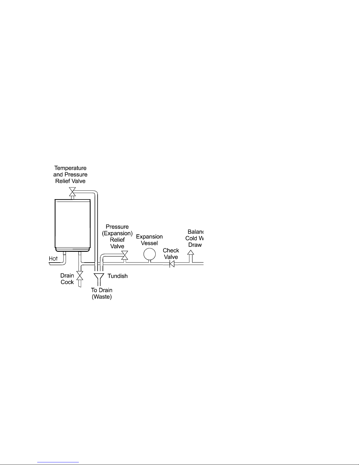
Diagram 1 Schematic Installation Diagram
WARNING: IF WATER FLOWS FROM THE PRESSURE RELIEF VALVE OR TEMPERATURE/PRESSURE RELIEF VALVE THE ELECTRICITY SUPPLY MUST BE
SWITCHED OFF IMMEDIATELY AND PROFFESIONAL ADVICE SOUGHT.
1.2 Expansion must be accommodated within the system. Use of the Expansion Vessel
and Check Valve provided in the Installation Kit will fulfill this function.
1.3 The installation of this water heater is covered by Building Regulation G3. In order
to fulfill the requirements of this Regulation the heater should be installed in
accordance with these instructions by a competent installer (i.e. an installer trained
in the installation of unvented water heating systems). All the control and safety
valves provided in the Installation Kit must be used and plumbed in accordance
with Diagram 1.
2.0 INSTALLATION - GENERAL REQUIREMENTS:
2.1 This Heatstore water heater must be installed by a competent installer in accord-
ance with Building Regulation G3.
2.2 National Wiring rules may contain restrictions concerning the installation of these
units in bathrooms.
2.3 The unit should be vertically wall mounted using the wall bracket and levelling feet
supplied. The water connections must always be on the bottom of the unit.
2.4 Enough space should be left below the unit for pipe connections and above the
unit for access to the Temperature/Pressure Relief Valve. Refer to Diagram 2 and
the Dimensions Table to determine a suitable position for the heater.
HEATSTORE
30 OR 50
LITRE
HE AT ER

4
3.0 INSTALLATION - WALL MOUNTING
3.1 Using Diagram 2 and the Dimensions Table as a guide mark the position of the
wall mounting bracket and lower location point. Drill and plug the wall with
suitable fixings, fix the wall bracket to the wall.
3.2 Fit the heater wall bracket to the rear of the unit using the screws provided
ensuring the central location bolt is pointing towards the bottom of the unit.
3.3 Remove the backing paper from the self adhesive pads of the Levelling Feet and
affix them to the lower back of the unit in the approximate positions shown on
Diagram 3.
3.4 Hang the unit on the wall mounting bracket ensuring the location bolt locates in
the hole in the wall bracket. Position the moulded spacer block between the tab
on the bottom cover moulding and the wall. Insert a No. 10 x 2 1/2long screw
through the tab and spacer block and tighten into wall plug.
2.5 NOTE: Ensure that the wall can support the full weight of the unit (see TECHNI-
CAL SPECIFICATIONS) and that there are no hidden services (electricity, gas, or
water) below the surface of the wall.
2.6 DO NOT install where the unit may freeze.
50 Litre30 LitreDim ension
888616A
937665B
1060788C
678506D
Diagram 2 Dimensions
 Loading...