

Heatstore HS2000T Installation And Operating Instructions Manual

Installation and Operating Instructions
Downflow Fan Heater Model : HS2000T
(IP22)08/54400/0 Issue 1
THESE INSTRUCTIONS SHOULD BE READ CAREFULLY AND RETAINED FOR FUTURE REFERENCE
IMPORTANT SAFETY ADVICE
This appliance can be used by children
aged from 8 years and above and
persons with reduced physical, sensory or
mental capabilities or lack of experience
or knowledge if they have been given
supervision or instruction concerning the
use of the appliance in a safe way and
understand the hazards involved. Children
shall not play with the appliance. Cleaning
and user maintenance shall not be made
by children without supervision. Children
of less than 3 years should be kept away
unless continuously supervised. Children
aged from 3 years and less than 8 years
shall only switch on/o the appliance
provided that it has been placed or installed
in its intended normal operating position
and they have been given supervision
or instruction concerning the use of the
appliance in a safe way and understand
the hazards involved. Children aged from 3
years and less than 8 years shall not plug in,
regulate and clean the appliance or perform
user maintenance.
CAUTION:
Some parts of this product can become
very hot and cause burns. Particular
attention has to be given where children
and vulnerable people are present.
WARNING:
This heater is not equipped with a device
to control room temperature. Do not use
this heater in small rooms when they are
occupied by persons not capable of leaving
the room on their own, unless constant
supervision is provided.
WARNING:
Do not operate the heater with the top
cover removed. This could trip the fuselink.
This heater must not be operated without
the cover correctly in position.
This heater carries the warning symbol
indicating that it must not be covered.
WARNING:
In order to avoid a hazard due to
inadvertent resetting of the thermal cutout, this appliance must not be supplied
through an external switching device, such
as a timer, or connected to a circuit that is
regularly switched on and o by the utility.
DO NOT place the heater directly below a
fixed socket outlet.
DO NOT place aerosols or other containers
susceptible to heat in the direct airflow
from the unit.
DO NOT use the heater in the immediate
surroundings of a bath, a shower or a
swimming pool.
IMPORTANT:
This heater must be installed so that the
switches and other controls cannot be
touched by a person in the bath or shower.
WARNING: Disconnect the heater from
the electricity supply before undertaking
service or repair.
WARNING:
If the appliance is fitted in a bathroom,
a cable outlet will be necessary with the
supply to the unit controlled by a double
pole switch. The switch if inside the
bathroom should be pull cord operated
and if outside should be adjacent to the
entrance door. The appliance must be
mounted so that no part of it can be
touched by any person using bath or
shower.
DO NOT cover the appliance or place
material or garments on it, or obstruct the
air circulation around this appliance, for
example with curtains or furniture, as this
could cause over heating and a fire risk.
WARNING: The supply circuit to the heater
must incorporate a double pole isolating
switch having a contact separation of at
least 3mm.
This product is only suitable for well
insulated spaces or occasional use.
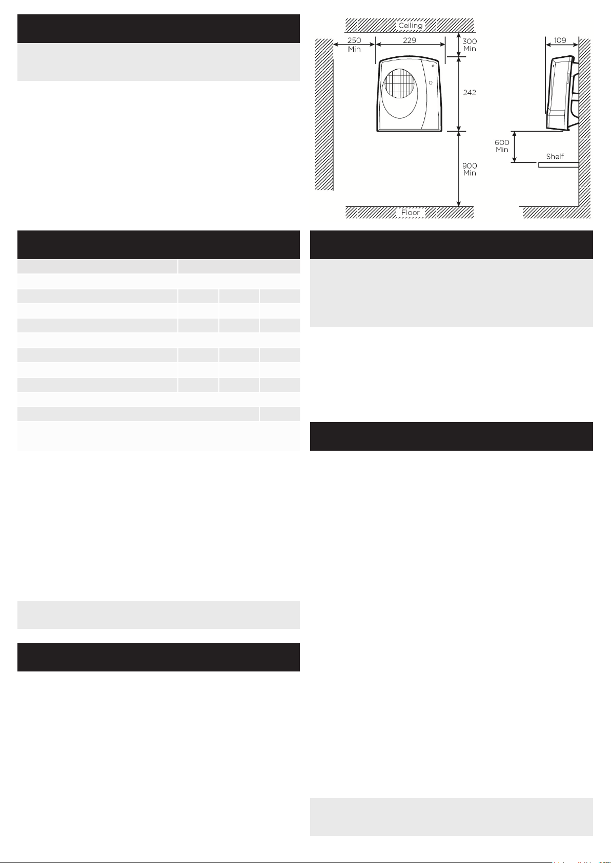
Dimensions (millimetres)
Model Specification
HS2000T: 1 or 2kW + electronic run-back timer
Fig. 1
General
Model Identifier(s) HS2000T
Heat output
Nominal heat output Pnom 2.0 kW
Minimum heat output (indicative) Pmin 1.0 kW
Maximum continuous heat output Pmax,c 2.0 kW
Auxillary electricity Consumption
At nominal heat ourput elmax 0.0 kW
At minimum heat output elmin 0.0 kW
In standby mode elSB 0.002 kW
type of heat output/room temperature control
With electronic 30 minute runback timer Ye s
Contact details:
Heatstore, Unit 12, Access 12, Bristol, BS11 8HT
The heater has a loading of 2kW. It is designed for permanent wall
mounting and is suitable for operation on A.C. electricity supply having
the same voltage as shown on the rating label. The heater is fitted
with an internally mounted selector switch which on installation of the
heater allows a choice of 1kW or 2kW output to suit the dimensions of
the room to be heated.
In rooms of less than 9 – 11 cubic m. (350 - 400 cubic ft.) 1kW output
should be selected, otherwise nuisance tripping of the thermal overload
cut-out may occur. The heater is fitted with an internally mounted selector
switch which on installation of the heater allows a choice of 1kW or 2kW
output to suit the dimensions of the room to be heated.
NOTE: The switch has been factory set for 1kW operation.
If additional output is required, 2kW can be set on installation.
Safety
Thermal Cut-Out & Electronic overheating protection
For your safety, this appliance is fitted with a thermal cut-out and
also an electronic overheat protection device. In the event that the
product overheats, these devices will switch the heater o automatically.
To bring the heater back into operation, remove the cause of overheating,
then turn o the electrical supply to the heater for a few minutes.
When the heater has cooled suciently reconnect and switch on the
heater. If the heater does not re activate it is possible that the fuselink
has triggered, see Fuse link.
Fuse Link
A thermal fuse link is provided as an added safety feature. If the fuse
link operates and opens circuit it is the result of abnormal overheating
within the appliance. To ensure the future safe operation of the heater,
please contact Heatstore Customer Services
Installation
WARNING: Minimum clearances must be adhered to when
mounting the heater.
Supply cable is not supplied with this appliance and it
should therefore be installed by a competent electrician
in accordance with the latest IEE wiring regulations.
Before undertaking installation work, ensure the electricity supply is
disconnected from any relevant fixed wiring.
The supply circuit must be adequate for the input of the appliance and
must be protected with a 13A fuse. A suitable termination to the fixed
wiring of the premises must be provided adjacent to the final position of
the appliance through a double pole switch having a contact separation
of at least 3mm in all poles.
Installation Procedure
It is essential to observe minimum wall mounting clearances - see Fig.
1. The appliance should be fitted horizontally, with the cable entry at
the top and grille at the bottom. It must be mounted not less than
900mm above the floor with a clearance of at least 600mm to any
shelf or projecting surface below the heater and not less than 300mm
below the ceiling or other projecting surface. It must also be not less
than 250mm from an adjacent projecting surface. For most eective
heating performance, the heater should be mounted at the minimum
height : i.e. 900mm above the floor. Care must be taken to ensure that
when in use, the air stream is not obstructed. The appliance is secured
to the wall with three screws, two through keyhole slots and one
through a hole to hold the appliance firmly in position (see Fig. 2)
1. Remove the top cover from the appliance by removing the two screws
securing the top cover and hinging it back.
2. Mark the position of the two keyhole slots (see Fig. 2 for dimensions)
on the wall and drill and plug for the two suitable screws.
3. Partially insert the two screws, then hang the appliance on the screws.
Mark the position of the third hole. This is used to secure the product.
4. Remove the appliance and drill and plug for the third screw.
5. Remount the appliance on the wall using the two keyhole slots.
6. Feed the supply cord or wires through the inlet at the top rear of the
appliance leaving sucient free length to connect to the terminal
block.
7. Make electrical connections to the terminal block ensuring that the
live connection is made to the terminal marked ‘L’ and the neutral
connection to the terminal marked ‘N’ (see Fig. 2 detailed view).
8. Fix the product inplace by inserting and tightening the third screw.
Fix mains cable securely using the products cable clamp
9. Set the selector switch to provide either 1kW or 2kW output.
10. Replace the top cover and screws.
The appliance is now ready for use and the electricity supply can be
reinstated.
WARNING: This product should never be operated without the
top cover correctly installed. In this case, a replacement product or
element would be required.
 Loading...