

Heatstore HS10U, HS15U Installation And User Instructions Manual
MULTIPOINT
1
Installation and User Instructions
HS10U, HS15U.
.
Please read and understand these instructions before starting work.
Please leave this leaflet with the user following installation
PACK CONTENTS
Heater, Factory fitted temperature and pressure relief valve, Fixing
screws and plugs, Installation and User Instructions.
WARNING
This water heater must only be installed by qualified persons.
36005794 Issue 2

2
Please read and understand these instructions prior to installing your Heatstore
unvented water heater. Particular attention should be paid to the section headed
IMPORTANT INSTALLATION POINTS. Following installation and commissioning
the operation of the heater should be explained to the customer and these instructions
left with them for future reference.
TECHNICAL SPECIFICATIONS
Electrical rating .................................................... 2.75kW @ 230V
..................................................... 3kW @ 240V
Capacities ............................................................. 10 or 15 litres
Weight (full) ......................................................... 10 litre - 16.4 kg
............................................................................. 15 litre - 23.1 kg
Rated pressure ..................................................... 6 bar (0.6 MPa)
Minimum recommended supply pressure ............ 0.8 bar (0.08 MPa)
Temperature/Pressure Relief Valve ....................... 90oC/7 bar
1.0 IMPORTANT INSTALLATION POINTS
1.1 This unvented water heater MUST be fitted with a Pressure Relief Valve. The
factory fitted Temperature/Pressure Relief Valve can fulfill this function. FAILURE
TO PROVIDE ADEQUATE PRESSURE RELIEF WILL INVALIDATE ANY
GUARANTEE AND LEAD TO A DANGEROUS INSTALLATION
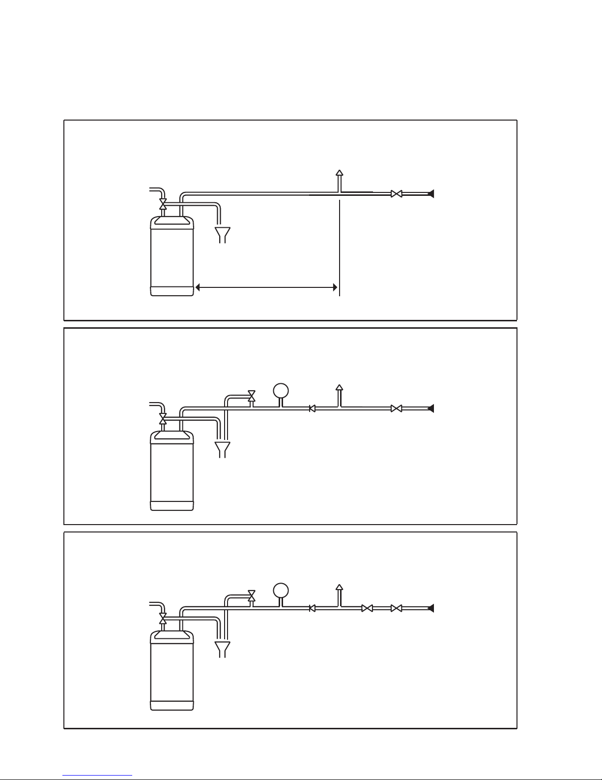
1.2 Expansion can take place within the cold water supply PROVIDED THAT BOTH :
(a) Backflow in the main is not prevented by any stopvalve with loose jumper,
check valve, pressure reducing valve or similar, AND
(b) Hot water expansion does not enter a branch to a cold water outlet (see
Figure 1 for expansion pipe lengths).
N.B. Both the above conditions must be met. Additionally expansion within the cold
water supply will not be possible if the static supply pressure exceeds 4.1 bar
(60p.s.i.).
1.3 If any of the conditions in 1.2 above cannot be met expansion must be
accomodated using an Expansion Vessel. To ensure all expansion takes place in
the vessel Non Return Valve must also be fitted together with a Pressure
(expansion) Relief Valve (see Figure 2). Use Accessory Pack B.
1.4 If the static supply pressure exceeds 4.1 bar (60p.s.i.) a Pressure Reducing Valve
must be fitted to the cold main supply. If a Pressure Reducing Valve is used an
Expansion Vessel must also be used (see Figure 3). Use Accesory Packs A and B.
MULTIPOINT
3
WARNING:
IF WATER FLOWS FROM THE PRESSURE RELIEF VALVE OR
TEMPERATURE / PRESSURE RELIEF VALVE THE ELECTRICITY SUPPLY
MUST BE SWITCHED OFF IMMEDIATELY AND PROFESSIONAL ADVICE
SOUGHT.
3
HS10U
OR
HS15U
HOT
COLD
TUNDISH
TO DRAIN
(WASTE)
NEAREST COLD
DRAW OFF
SERVICE
VALVE
2.8 (10L) OR 4.2 (15L) METERS
IS REQUIRED FOR EXPANSION
IN PIPEWORK.
HS10U
OR
HS15U
HOT
COLD
TUNDISH
TO DRAIN
(WASTE)
EXPANSION
VESSEL
NON RETURN
VALVE
NEAREST COLD
DRAW OFF
SERVICE
VALVE
PRESSURE
(EXPANSION)
RELIEF VALVE
HS10U
OR
HS15U
HOT
COLD
TUNDISH
TO DRAIN
(WASTE)
EXPANSION
VESSEL
NEAREST COLD
DRAW OFF
PRESSURE
REDUCING
VALVE
SERVICE
VALVE
PRESSURE
(EXPANSION)
RELIEF VALVE
COLD
WATER
MAINS
NOTE: IF PRESSURE REDUCING VALVE
IS USED EXPANSION DOWN THE MAINS
IS NOT POSSIBLE
FIGURE 1: FOR INLET WATER PRESSURES UP TO 4.1 BAR (60 P.
S.I.) - NO ADDITIONAL KITS USED.
COLD
WATER
MAINS
FIGURE 2 : FOR INLET WATER PRESSURES UP TO 4.1 BAR (60 P.S.I.)
WHERE EXPANSION IN MAIN SUPPLY IS NOT POSSIBLE - USING PACK B.
COLD
WATER
MAINS
FIGURE 3 : FOR INLET WATER PRESSURES ABOVE 4.1 BAR (60 P.S.I.) - USINK PACKS A AND B.
NON RETURN
VALVE
4
2.0 INSTALLATION - GENERAL REQUIREMENTS:
2.1 National Wiring rules may contain restrictions concerning the installation of these
units in bathrooms.
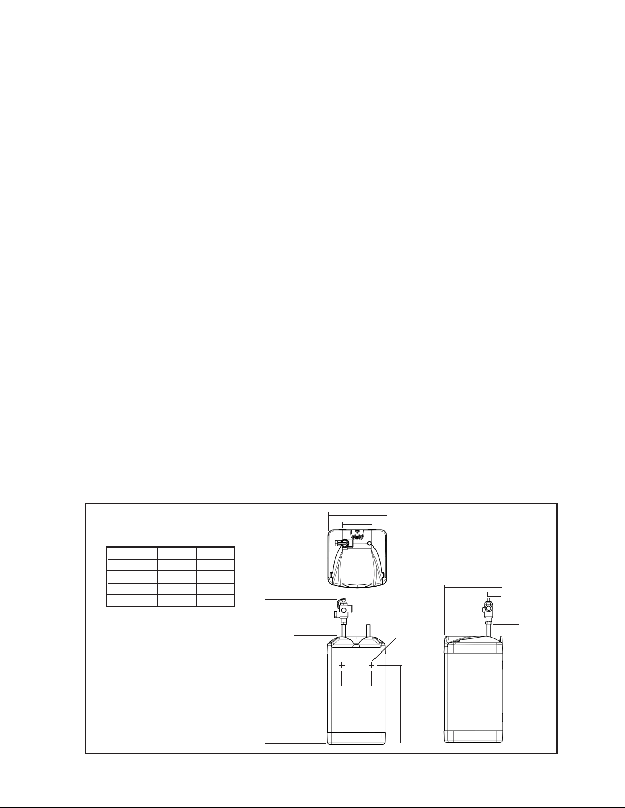
2.2 The unit should be vertically wall mounted. Fixing screws and rawplugs are
supplied for this purpose. Refer to Figure 4 for position of fixing holes. The water
connections must always be to the top of the unit.
2.3 Enough space should be left at the top above the unit for pipe connections and
access to the Temperature/Pressure Relief Valve. Refer to Figure 4 and the
Dimensions Table to determine a suitable position for the heater.
2.4 NOTE: Ensure that the wall can support the full weight of the unit
(see TECHNICAL SPECIFICATIONS) and that there are no hidden services
(electricity, gas, or water) below the surface of the wall.
2.5 DO NOT install where the unit may freeze.
2.6 Refer to the section IMPORTANT INSTALLATION POINTS to determine which
valves and accessories are required. Plumb in the valves in the sequence shown in
the relevant Diagrams ( Figures 1, 2, and 3).
2.7 The inlet water connection is a 15mm diameter copper tube suitable for
compression fittings.
The outlet water connection is made to the 15mm commpression fitting located on
the factory fitted temperature and pressure relieve valve.
A WRAS listed isolating valve (not supplied) must be fitted on the cold water
supply to the heater. Several hot outlets can be served.
2.8 Do not use solder joints as this will damage the heater and may prevent servicing
under warranty.
2.9 Plumbers Paste must not be used as it can impair the operation of the valves.
240
120
50
240
100
A
D
C
B
2 KEYHOLE
FIXING SLOTS
6mm WIDE
DIMENSION 10 LITRE 15 LITRE
A 442mm 598mm
B 478mm 634mm
C 492mm 648mm
D 322mm 478mm
FIGURE 4: DIMENSIONS
 Loading...