

Page 1
NEVER LEAVE THE HEATER UNATTENDED WHILE BURNING!NEVER LEAVE THE HEATER UNATTENDED WHILE BURNING!NEVER LEAVE THE HEATER UNATTENDED WHILE BURNING!
OPERATING INSTRUCTIONS
AND OWNER’S MANUAL
READ INSTRUCTIONS CAREFULLY: YOUR SAFETY IS IMPORTANT TO YOU AND TO OTHERS.
Read and follow all instructions. Place instructions in a safe place for future reference. Do not allow
anyone who has not read these instructions to assemble, light, adjust or operate the heater.
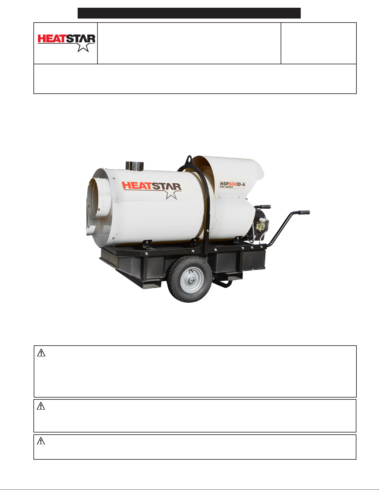
MODEL#
HSP500ID-A
PORTABLE INDUSTRIAL OIL-FIRED
INDIRECT HEATER
WARNING: If the information in this manual is not followed exactly, a fire or explosion
may result causing property damage, personal injury, or loss of life.
– Do not store or use gasoline or other flammable vapors and liquids in the vicinity of this or any
other appliance.
– Service must be performed by a service agency.
WARNING: Improper adjustment, alteration, service or maintenance can cause injury or property
damage. Refer to this manual for correct installation and operational procedures. For Assistance or
additional information consult a service agency.
WARNING: This is an indirect oil-fired portable heater. It uses air (oxygen) from the area in which
it is used. Provisions for adequate combustion and ventilation air must be provided.
ENERCO GROUP, INC., 4560 W. 160TH ST., CLEVELAND, OHIO 44135 · 866-447-2194
Page 2
NEVER LEAVE THE HEATER UNATTENDED WHILE BURNING!NEVER LEAVE THE HEATER UNATTENDED WHILE BURNING!NEVER LEAVE THE HEATER UNATTENDED WHILE BURNING!
IMPORTANT: READ THIS OWNER’S MANUAL CAREFULLY AND COMPLETELY BEFORE TRYING
TO ASSEMBLE, OPERATE, OR SERVICE THIS HEATER. IMPROPER USE OF THIS HEATER CAN
CAUSE SERIOUS INJURY OR DEATH FROM BURNS, FIRE, EXPLOSION, ELECTRICAL SHOCK,
AND/OR CARBON MONOXIDE POISONING.
GENERAL HAZARD WARNING:
ONLY PERSONS WHO CAN UNDERSTAND
AND FOLLOW THE INSTRUCTIONS SHOULD
USE OR SERVICE THIS HEATER.
WARNING: FIRE, BURN, INHALATION,
AND EXPLOSION HAZARD. KEEP SOLID
COMBUSTIBLES, SUCH AS BUILDING
MATERIALS, PAPER, OR CARDBOARD A
SAFE DISTANCE AWAY FROM THE HEATER.
AS RECOMMENDED BY THE INSTRUCTIONS
NEVER USE THE HEATER IN SPACES WHICH
DO OR MAY CONTAIN VOLATILE OR
AIRBORNE COMBUSTIBLES, OR PRODUCTS
SUCH AS GASOLINE, SOLVENTS, PAINT
THINNER, DUST PARTICLES, OR UNKNOWN
CHEMICALS.
DANGER: CARBON MONOXIDE
POISONING MAY LEAD TO DEATH. USING A
PORTABLE HEATER IN AN ENCLOSED AREA
CAN PRODUCE DEADLY CARBON MONOXIDE.
CARBON MONOXIDE POISONING:
Early signs of carbon monoxide poisoning
resemble the flu, with headaches, dizziness,
or nausea. If you have these signs, the heater
may not be working properly. Get fresh air
at once! Have heater serviced. Some people
are more affected by carbon monoxide than
others. These include pregnant women,
persons with heart or lung disease or anemia,
those under the influence of alcohol, and
those at high altitudes.
WARNING: NOT FOR HOME OR
RECREATIONAL VEHICLE USE
THE STATE OF CALIFORNIA REQUIRES THE
FOLLOWING WARNING:
WARNING: This product can expose you to
chemicals including lead and lead compounds,
which are known to the State of California
to cause cancer and birth defects or other
reproductive harm. For more information visit
www.P65Warnings.ca.gov
CONTENTS
HAZARD WARNINGS ................................................. 2
CLEARANCES TO COMBUSTIBLES .............................. 3
SPECIFICATIONS ......................................................... 3
PRECAUTIONS ............................................................ 3
UNPACKING & ASSEMBLY .......................................... 4
FRESH AIR AND VENTILATION ................................... 5
OPERATION ............................................................... 6
TRANSPORTATION ..................................................... 8
STORAGE ................................................................... 8
MAINTENANCE .......................................................... 8
TROUBLESHOOTING .................................................. 9
PARTS LIST AND DIAGRAM ....................................... 10
WIRING .................................................................... 19
Portable Indirect Oil-Fired Heaters
CONTACT INFORMATION
RETAIN THIS MANUAL FOR FUTURE REFERENCE.
FOR QUESTIONS, PROBLEMS, MISSING PARTS BEFORE RETURNING
TO RETAILER PLEASE CALL WITH MODEL NUMBER AND SERIAL
NUMBER OF HEATER:
866-447-2194
MONDAY-FRIDAY 8-5 EASTERN TIME
OR E-MAIL USING THE HEATSTAR WEBSITE:
WWW.HEATSTARBYENERCO.COM
In order to provide the best service possible HEATSTAR is now
giving you more ways to get in touch with us. Find informational
videos at:
YouTube: youtube.com/heatstarTV
HEATSTAR’S full line of product are now at:
WWW.HEATSTARBYENERCO.COM
Installation Instructions and Owner’s Manual
2
Page 3
NEVER LEAVE THE HEATER UNATTENDED WHILE BURNING!NEVER LEAVE THE HEATER UNATTENDED WHILE BURNING!NEVER LEAVE THE HEATER UNATTENDED WHILE BURNING!
SPECIFICATIONS
Heat Input (Max) (kBTU/hr) 500 (400 - Setting From Factory)
CFM Output/Static Pressure 4,032/1.08” WC
Fuel Types • #1 or #2 Fuel Oil
• K-1 Kerosene
Fuel Consumption (Max) (gal/h) 3.6 (2.9 - Setting From Factory)
Steinen Nozzle
Capacity (Max) (gal/hr)
Spray Angle (deg)
Spray Pattern
Pump Pressure 174 psi/1200 kPa/12 bar
Power Supply 1 Phase, 120V, 60Hz, 13.4A
Dimensions (L” x W” x H”) 68 x 27 x 60
Dry Weight (lb) 494
If you need assistance or heater information such as a instructions manuals, labels, etc. contact the
manufacturer.
2.75 (2.25 - Setting From Factory)
60
Solid
CLEARANCES TO COMBUSTIBLES
Clearances between these HEATSTAR PRO
indirect heaters and adjacent combustible
material (which is part of the building or its
contents) shall not be less than:
Top: 5ft (1.5m)
Sides: 5ft (1.5m)
Front: 8.5ft (2.5m)
Back: 5ft (1.5m)
THEORY OF OPERATION
The burner pump aspires the fuel from the tank
and sends it to the pressurised nozzle, where
it is nebulised and mixed to the comburent air
in the combustion chamber. A spark triggers
combustion while the exhaust fumes are
expelled from the chimney. A series of sensors
constantly checks the correct operation of the
heater, stopping the cycle in the case of a fault.
The fan, located at the rear of the heater, cools
the combustion chamber and the flue gas
pass, transferring heat from the latter into the
environment.
PRECAUTIONS
Caution: When using Thermostat, heater
can start unexpectedly. Turn heater off when
unattended.
WARNING:
• DO NOT USE GASOLINE, NAPHTHA OR
VOLATILE FUELS.
• STOP HEATER BEFORE ADDING FUELS.
• ALWAYS FILL OUTDOORS AWAY FROM
OPEN FLAME
• DO NOT OPERATE HEATER WHERE
FLAMMABLE LIQUIDS OR VAPORS MAY BE
PRESENT
• DO NOT START HEATER WHEN EXCESS
FUEL HAS ACCUMULATED IN THE
CHAMBER
• DO NOT PLACE COOKING UTENSILS ON
TOP OF THE HEATER.
• PLUG ELECTRICAL CORD INTO A PROPERLY
GROUNDED THREE-PRONG RECEPTACLE.
Portable Indirect Oil-Fired Heaters
Installation Instructions and Owner’s Manual
3
Page 4
NEVER LEAVE THE HEATER UNATTENDED WHILE BURNING!NEVER LEAVE THE HEATER UNATTENDED WHILE BURNING!NEVER LEAVE THE HEATER UNATTENDED WHILE BURNING!
Circuit
Please observe the following precautions
when operating your HEATSTAR product.
1. Check the heater thoroughly for damage. DO
NOT operate a damaged heater.
2. Only a qualified service person should service
and repair heater.
3. Before using the heater, read and understand
all instructions and follow them carefully. The
manufacturer is not responsible for damages
to goods or persons due to improper use.
4. Operate only on a stable, level surface.
5. Not suitable for operation with external tank.
6. Check that fire-fighting equipment is available
and suitable to the potential of the heater.
7. The use of the unit shall be in accordance
with the regulations and legislation of
authorities having jurisdiction.
8. Make sure heater is always under surveillance
and keep children and animals away from it.
9. Do not operate the unit in close proximity to
combustible surfaces or materials.
10. Heaters used near tarpaulins, curtains or
other similar covering materials must be kept
at a safe distance. It is advised to use fire-
proof covering material.
11. If the heater will be installed, an exhaust gas
pipe connection must be installed.
Caution: When this heater is connected to
a flue pipe, the flue pipe shall terminate in
a vertical section at least two feet long and
sufficient draft shall be created to assure safe
and proper operation of the heater.
12. Heaters must be powered only with the
correct voltage and frequency values as
specified on the heater’s identification plate
or specifications table.
13. Keep all air inlet (rear) and air outlet (front)
clear, free of debris or any blockage.
14. Do not start the heater when the chamber is
hot.
regarding capacity, type of nozzles and pump
pressure. An increase in burner power could
damage the heater.
17. Turn off and unplug heater and let cool
before servicing or transporting.
18. Unplug heater when not in use.
UNPACKING
WARNING: The packaging material is not a
toy. Keep the plastic bag out of the reach of
children; danger of suffocation!
1. Remove all protective material which may have
been applied to the heater for shipment.
2. The heater is placed on a platform. Lift it
delicately using hooks and chains. Use the
holes on the structure to lift the heater.
3. Check the heater for possible shipping
damage. If any damage is found immediately
contact the manufacturer at 866-447-2194.
UNIT INSTALLATION
WARNING: Closely follow all the operations
described in this paragraph. Installation must
only be carried out by qualified personnel.
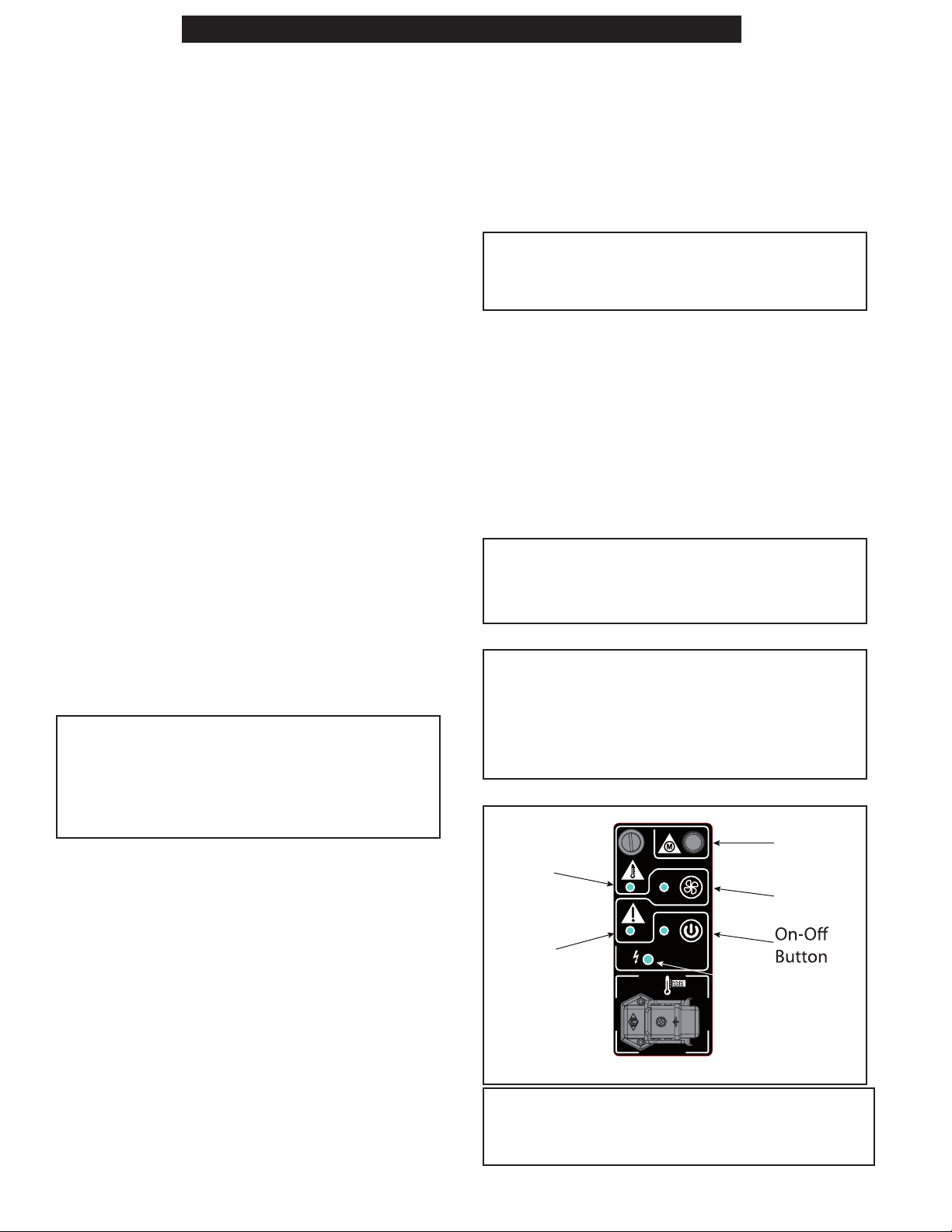
ELECTRIC AL CONNECTION
WARNING: When you connect the power
supply plug, check the light lamp with “spark
icon”. See Figure 1. In case the lamp stays
OFF, you must remove the plug, rotate it 180°
and reconnect.
Safety
Thermostat
Light
Burner
Reset
Light
Light Lamp
Breaker
Reset
Fan
Button
15. Do not attempt to use heater to cook or
warm food.
16. Use original spare parts when replacing the
burner, strictly complying with indications
Portable Indirect Oil-Fired Heaters
FIGURE 1
CAUTION: The electric power line of the heater
must be equipped with an grounding system,
residual current device, and cut-off switch.
Installation Instructions and Owner’s Manual
4
Page 5
NEVER LEAVE THE HEATER UNATTENDED WHILE BURNING!NEVER LEAVE THE HEATER UNATTENDED WHILE BURNING!NEVER LEAVE THE HEATER UNATTENDED WHILE BURNING!
The standard supply of the heater includes
all the control and safety devices essential for
its proper operation: electric panel, burner,
manually reset safety thermostat are already
connected.
During installation, prepare the power supply
connection with cables having an appropriate
cross-section in compliance with national
standards in force and the technical data label
applied to the heater.
NOTE: CHECK THE ELECTRIC CONNECTIONS
BEFORE STARTING THE HEATER.
DUCT ADAPTERS
The heater comes with a dual 12” duct adapter
attached. A single 16” duct adapter is available
as an additional accessory as shown in Table 1
below.
ADDITIONAL ACCESSORIES
Table 1 details additional accessories approved
for use with the heater. Instructions for assembly
and operation of accessories are included in
accessory’s packaging.
TABLE 1: ADDITIONAL ACCESSORIES CHART
Description Part Number
OPERATION
BEFORE SWITCHING HEATER ON
Before any attempt of starting the heater
is made, familiarize yourself with warnings,
specifications and precautions page 2 - 5.
• Check that the fuel is appropriate. Check
that there is sufficient fuel in the fuel tank by
reading the fuel gage. If not already closed,
close the tank cap by rotating it clockwise. It
is recommended to use winter diesel oil below
ambient temperatures of 41 °F.
• Check that minimum safety clearances from
combustibles, listed in “CLEARANCES TO
COMBUSTIBLES” on page 3, is achieved in
all directions.
• Make sure that flue gas is adequately ventilated
from the chimney.
• Attach a duct to the outlet if directed venting
of output clean hot air is desired. Ducting can
be installed with the specific clamp or quick
coupling. Refer to “ACCESSORY CHART” on
page 18 for the correct Duct adapter.
• Check that your electrical supply and any
extension cable can meet the requirements
listed in the specifications table.
Air Recycle
Kit
Digital
Thermostat
Analog
Thermostat
Single Duct
Adapter 16”
F105128 24”x25’ Duct & 24” Clamp
F105127 Adapter Ring
F105106
F105108
F 10512 6
FLUE GAS EXHAUST CONNECTION
Thermal efficiency and correct operation of the
heater are directly linked to the correct draught of
the flue gas exhaust chimney. It is recommended
not to make elbows, which may get clogged, or
reductions in the cross-section of the flue gas
exhaust chimney. If the heater is not connected to
an external flue gas exhaust chimney, it must be
provided with an essentially vertical steel flue gas
exhaust and a draught regulator, respecting the
specifications provided in this technical manual.
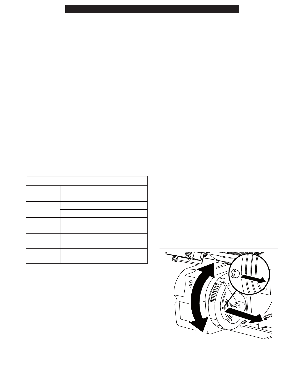
SWITCH-ON
1. Check the presence of fuel inside the gas
tank.
2. Connect the heater to the electrical supply.
3. Adjust the air damper of the burner according
to your needs. See Figure 2.
FIGURE 2
Portable Indirect Oil-Fired Heaters
Installation Instructions and Owner’s Manual
5
Page 6

NEVER LEAVE THE HEATER UNATTENDED WHILE BURNING!NEVER LEAVE THE HEATER UNATTENDED WHILE BURNING!NEVER LEAVE THE HEATER UNATTENDED WHILE BURNING!
START-UP IN HEATING MODE
Press the on-off button (the burner starts first
and after about one minute, ventilation starts).
Refer to the Control Panel in Figure 1.
NOTE: THE HEATER HAS A SENSOR THAT
CONSTANTLY MONITORS THE OUTLET AIR
TEMPERATURE [FOR NORMAL OPERATION,
THE OUTLET AIR TEMPERATURE MUST BE
BELOW 105˚C (221˚F). IF THE OUTLET AIR
TEMPERATURE EXCEEDS 105˚C (221˚F), THE
HEATER TURNS OFF THE BURNER. WHEN THE
TEMPERATURE RETURNS BELOW 105˚C (221˚F),
THE BURNER AUTOMATICALLY REACTIVATES.
UNDER 105˚C (221˚F) THE HEATER MODULATES
VENTILATION TO ENSURE THE BEST OUTLET
AIR TEMPERATURE, IN RELATION TO THE
ENVIRONMENTAL CONDITIONS DETECTED.
START-UP IN VENTILATION MODE
Press the fan button. See Figure 1.
SWITCHING OFF THE HEATER:
IMPORTANT: Never unplug the heater to
switch it off or before it is completely off.
The heater turns off by pressing the “OFF”
button. The burner box will turn off, and the fan
will continue running to cool off the burner box.
Do not unplug the heater until this cooling
cycle has totally ended. When the outlet air
temperature drops below 50˚C (122˚F), the fan
turns off and the luminous signal of the button
turns on to indicate the presence of voltage
(stand-by condition).
RESETTING THE HEATER
The appliance stops when an anomaly occurs.
RESETTING THE BURNER: If the burner is blocked,
the indicator light on the control panel turns on.
Refer to Figure 1. Identify and remove the cause
of the block. To reactivate the burner, press the
reset button on it for at least 10 seconds. See
Figure 3.
Burner
Reset
Button
FIGURE 3
RESETTING THE SAFETY THERMOSTAT: Safety
thermostat operation is identified by an indicator
light. Refer to Figure 1. Identify and remove the
cause that triggered the safety thermostat. Press
the reset button located at the back of the heater
all the way.
RESETTING THE CIRCUIT BREAKER: Identify and
remove the cause of activation of the circuit
breaker. Press the reset button to release it. See
Figure 1.
THE EXTERNAL THERMOSTAT SOCKET
The heater can only work automatically when a
control device, such as a thermostat or a timer,
is connected to the heater. F105106, a 33ft
digital Thermostat, and F105108, a 33ft analog
thermostat are both approved for use by the
manufacturer with the heater. Connection to
the heater is made by removing the thermostat
socket cap and connecting the room thermostat
to the socket. If no room thermostat will be
connected the cap must be inserted into the
socket.
Portable Indirect Oil-Fired Heaters
Installation Instructions and Owner’s Manual
6
Page 7

NEVER LEAVE THE HEATER UNATTENDED WHILE BURNING!NEVER LEAVE THE HEATER UNATTENDED WHILE BURNING!NEVER LEAVE THE HEATER UNATTENDED WHILE BURNING!
TRANSPORTATION
Before any handling, the heater must be
switched off following the proper procedure, and
disconnected from the electrical and gas supply.
Wait for the heater to cool.
Before handling, make sure that the support
used to move the heater is capable of bearing its
weight (the weight is displayed on the technical
specification of the appliance). Do not attempt to
lift or move the heater without the aid of suitable
equipment (this operation must be carried out
with the utmost attention to avoid personal harm
or damage to the heater).
STORAGE
IN ORDER TO KEEP THE HEATER IN THE BEST
POSSIBLE CONDITIONS, WE RECOMMEND
FOLLOWING THE PROCEDURE BELOW:
• Place the heater in a dry place away from
potential external damage.
FIGURE 4
2. Remove the plates, which close the inspection
openings, by removing the screws. See Figure
5.
Screw
Inspection Opening
MAINTENANCE
WARNING:
Never service heater while it is plugged in,
operating or hot. Severe burns or electrical
shock can occur.
Periodic maintenance is recommended to keep
the heater in good condition, avoiding possible
failures or faults as far as possible.
CLEANING THE FAN
Use compressed air for routine cleaning of the
fan, blowing the air through the rear grille.
CLEANING THE BURNER
Read and understand the specific manual to clean
the burner.
CLEANING THE COMBUSTION CHAMBER
It is recommended to clean the combustion
chamber and flue gas duct at least once a
year or when required to avoid problems
regarding chimney draught and combustion. The
combustion chamber is cleaned through the five
inspection openings on the front of the heater.
Closely follow this sequence to perform cleaning
(keep the screws and washers with care):
1. Remove the air ducting cone by removing
the screws which secure it to the heater. See
Figure 4.
Portable Indirect Oil-Fired Heaters
Gasket
FIGURE 5
3. Remove the gaskets installed and do not reuse
them. Only use new and original gaskets. See
Figure 5.
4. Spray high pressure water inside the chamber
through the inspection openings. Refer to
Figure 5. When washing, move the nozzle in
various positions so the water reaches all the
slots of the combustion chamber.
5. Lift the combustion chamber from the back
to empty as much water as possible from
inside the chamber (this operation must be
carried out with the utmost attention to avoid
personal harm or damaging the heater).
6. Reassemble the heater performing the
sequence of operations in the opposite order,
replacing the gaskets with original spare
parts.
NOTE: BEFORE SWITCHING THE HEATER BACK
ON, MAKE SURE AS MUCH WATER AS POSSIBLE
HAS BEEN ELIMINATED FROM INSIDE THE
COMBUSTION CHAMBER TO AVOID SERIOUS
DAMAGE.
Installation Instructions and Owner’s Manual
7
Page 8

NEVER LEAVE THE HEATER UNATTENDED WHILE BURNING!NEVER LEAVE THE HEATER UNATTENDED WHILE BURNING!NEVER LEAVE THE HEATER UNATTENDED WHILE BURNING!
WARNING: BEFORE STARTING ANY MAINTENANCE OR REPAIRS, DISCONNECT THE POWER CABLE
AND MAKE SURE THAT THE HEATER IS COLD.
TABLE 4: PREVENTATIVE MAINTENANCE SCHEDULE
COMPONENT MAINTENANCE FREQUENCY
Safety Thermostat Yearly check and/or when required
Nozzle Replace yearly and/or when required
Electrical System Yearly check and/or when required
Fan Yearly check and/or when required
Motor Yearly check and/or when required
Fuel Pump Yearly check and/or when required
Combustion chamber Yearly check and/or when required
TROUBLESHOOTING
OBSERVED
SYMPTOM
The heater
does not
start or
does not
remain on
POSSIBLE CAUSE REMEDY
No power supply • Check that there is electric power
• Check that the heater is connected to the correct power supply
• Contact an authorized technical support center or HEATSTAR
customer service
Interrupted power cable • Contact an authorized technical support center or HEATSTAR
customer service
Electronics need to be reset or are faulty • Reset the heater
• Contact an authorized technical support center or HEATSTAR
customer service
Incorrect setting of the room thermostat
(if applicable)
No gas supply • Refuel and, if necessary, reset the heater
• Set the room thermostat to a temperature higher than the tem-
perature of the working environment
MAINTENANCE PROCEDURE
Contact a technical service center.
Service of these components
should only be performed by a
qualified serviceman. Qualified
service professionals may contact
the manufacturer for a service
manual.
Foreign substances in the fuel system • Contact an authorized technical support center or HEATSTAR
customer service
The heater
generates
smoke
during
operation
The heater
does not
turn off
PARTS ORDERING INFORMATION:
PURCHASING: Accessories may be purchased at any HEAT STAR local dealer or direct from the factory
FOR INFORMATION REGARDING SERVICE
Please call Toll-Free 866-447-2194 • www.heatstarbyenerco.com
Our office hours are 8:00 AM – 5:00 PM, EST, Monday
through Friday. Please include the model number, date of purchase, and description of problem in all communication.
Foreign substances in the fuel system • Contact an authorized technical support center or HEATSTAR
customer service
Obstructed inlet air vent
Faulty electronic system
• Remove all possible obstructions from the rear grille
• Contact an authorized technical support center or HEATSTAR
customer service
Portable Indirect Oil-Fired Heaters
Installation Instructions and Owner’s Manual
8
Page 9

NEVER LEAVE THE HEATER UNATTENDED WHILE BURNING!NEVER LEAVE THE HEATER UNATTENDED WHILE BURNING!NEVER LEAVE THE HEATER UNATTENDED WHILE BURNING!
**PAGE LEFT INTENTIONALLY BLANK**
Portable Indirect Oil-Fired Heaters
Installation Instructions and Owner’s Manual
9
Page 10

NEVER LEAVE THE HEATER UNATTENDED WHILE BURNING!NEVER LEAVE THE HEATER UNATTENDED WHILE BURNING!NEVER LEAVE THE HEATER UNATTENDED WHILE BURNING!
PARTS LIST AND DIAGRAM
PARTS LIST AND DIAGRAM
HSP500ID-A
7
9
11
10
8
6
4
B
5
3
1
Portable Indirect Oil-Fired Heaters
2
14
Installation Instructions and Owner’s Manual
10
12
A
13
Page 11

NEVER LEAVE THE HEATER UNATTENDED WHILE BURNING!NEVER LEAVE THE HEATER UNATTENDED WHILE BURNING!NEVER LEAVE THE HEATER UNATTENDED WHILE BURNING!
PARTS LIST AND DIAGRAM
PARTS LIST AND DIAGRAM
HSP500ID-A
# P/N PART DESCRIPTION
1 51328 MOTOR
2 51329 MOTOR POWER CORD
3 5127 8 FAN
4 511 0 8 FIBER ROPE GASKET
5 51336 COVER
6 51337 INSPECTION FIBER GASKET
7 5133 8 INSPECTION FLANGE
8 513 4 0 DUCT ADAPTER
9 513 4 3 THERMOSTAT BRACKET
10 510 9 6 THERMOSTAT
11 51350 NTC SENSOR WIRE
12 514 59 BURNER POWER CORD
13 51115 BURNER COVER
14 51117 BURNER RESET CAP
NOTE: Not all parts available. For questions contact manufacturer.
WARNING: Failure to position the parts in accordance with these diagrams or failure to use only
parts specifically approved with this heater may result in property damage or personal injury.
Portable Indirect Oil-Fired Heaters
Installation Instructions and Owner’s Manual
11
Page 12

NEVER LEAVE THE HEATER UNATTENDED WHILE BURNING!NEVER LEAVE THE HEATER UNATTENDED WHILE BURNING!NEVER LEAVE THE HEATER UNATTENDED WHILE BURNING!
PARTS LIST AND DIAGRAM
PARTS LIST AND DIAGRAM
HSP500ID-A (Sub-Assembly B)
18
9
16
17
14
15
2
8
10
11
13
12
7
6
5
4
3
B
Portable Indirect Oil-Fired Heaters
1
Installation Instructions and Owner’s Manual
12
Page 13

NEVER LEAVE THE HEATER UNATTENDED WHILE BURNING!NEVER LEAVE THE HEATER UNATTENDED WHILE BURNING!NEVER LEAVE THE HEATER UNATTENDED WHILE BURNING!
PARTS LIST AND DIAGRAM
PARTS LIST AND DIAGRAM
HSP500ID-A (Sub-Assembly B)
# P/N PART DESCRIPTION
1 514 2 5 PC-BOARD,HSP500ID-A
2 510 8 3 RELAY
3 5136 8 LED PC-BOARD
4 5136 9 LED PC-BOARD WIRES
5 5137 0 THERMOSTAT WIRES
6 5111 4 SAFETY THERMOSTAT
7 51138 TERMINAL BLOCK
8 51374 AUTOMATIC SWITCH
9 5137 6 BURNER WIRES
10 5137 7 90˚ SOCKET
11 5111 9 THERMOSTAT RESET CAP
12 5137 9 LIGHT CAP
13 5119 0 THERMOSTAT SOCKET
14 5119 3 THERMOSTAT CAP
15 511 9 1 PLUG,ROOM,TSTAT
16 513 8 5 POWER CORD
17 513 8 9 WIRES FOR MOTOR
18 513 9 0 SOCKET
NOTE: Not all parts available. For questions contact manufacturer.
WARNING: Failure to position the parts in accordance with these diagrams or failure to use only
parts specifically approved with this heater may result in property damage or personal injury.
Portable Indirect Oil-Fired Heaters
Installation Instructions and Owner’s Manual
13
Page 14

NEVER LEAVE THE HEATER UNATTENDED WHILE BURNING!NEVER LEAVE THE HEATER UNATTENDED WHILE BURNING!NEVER LEAVE THE HEATER UNATTENDED WHILE BURNING!
PARTS LIST AND DIAGRAM
PARTS LIST AND DIAGRAM
HSP500ID-A
5
7
6
6
20
18
10
19
16
8
21
9
22
11
12
13
14
1
NOTE: Not all parts available. For questions contact manufacturer.
WARNING: Failure to position the parts in accordance with these diagrams or failure to use only
parts specifically approved with this heater may result in property damage or personal injury.
4
17
3
2
Portable Indirect Oil-Fired Heaters
16
14
15
Installation Instructions and Owner’s Manual
Page 15

NEVER LEAVE THE HEATER UNATTENDED WHILE BURNING!NEVER LEAVE THE HEATER UNATTENDED WHILE BURNING!NEVER LEAVE THE HEATER UNATTENDED WHILE BURNING!
PARTS LIST AND DIAGRAM
PARTS LIST AND DIAGRAM
HSP500ID-A
# P/N PART DESCRIPTION
1 513 91 COTTER PIN
2 513 92 WHEEL WASHER
3 5112 8 PNEUMATIC WHEEL
4 510 91 WHEEL BUSHING
5 51336 COVER
6 51088 LIFTING ARC FOOT
7 510 8 9 LIFTING ARC
8 51135 ADAPTER BREATHE VALVE
9 51009 STRAIGHT CONNECTION
10 5127 6 TANK
11 51090 WHEEL AXEL
12 510 45 DRAIN PLUG
13 5112 4 TANK FILTER
14 5112 3 FUEL CAP
15 510 0 5 FUEL LINE - PUMP-FILTER
16 51137 NIPPLE,CONNECTOR
17 5113 6 FUEL FILTER
18 5125 8 RETURN FUEL LINE
19 51417 INTAKE FUEL LINE
20 51131 FUEL GAUGE
21 5113 0 COPPER INTAKE TUBE
22 51009 STRAIGHT CONNECTION
Portable Indirect Oil-Fired Heaters
Installation Instructions and Owner’s Manual
15
Page 16

NEVER LEAVE THE HEATER UNATTENDED WHILE BURNING!NEVER LEAVE THE HEATER UNATTENDED WHILE BURNING!NEVER LEAVE THE HEATER UNATTENDED WHILE BURNING!
PARTS LIST AND DIAGRAM
PARTS LIST AND DIAGRAM
HSP500ID-A (Sub-Assembly A)
19a
13a
8a
18a
15a
14a
20a
16a
17a
A
11a
Portable Indirect Oil-Fired Heaters
12a
6a
5a
7a
1a
2a
9a
10a
Installation Instructions and Owner’s Manual
16
4a
3a
Page 17

NEVER LEAVE THE HEATER UNATTENDED WHILE BURNING!NEVER LEAVE THE HEATER UNATTENDED WHILE BURNING!NEVER LEAVE THE HEATER UNATTENDED WHILE BURNING!
PARTS LIST AND DIAGRAM
PARTS LIST AND DIAGRAM
HSP500ID-A (Sub-Assembly A)
# P/N PART DESCRIPTION
1a 51251 MOTOR
2a 51252 PUMP
3a 51255 CAPACITOR
4a 51247 FAN
5a 5124 8 FILTER O-RING
6a 51249 NEEDLE VALVE
7a 514 35 COLLAR
8a 5112 5 ELECTRODE ASSEMBLY
9a 5124 6 COIL
10a 514 3 9 BRACKET WITH KNOB
11 a 51253 CONTROL BOX
12 a 514 41 TERMINAL BOARD
13 a 5112 6 END RING AND DIFFUSER DISC
14 a 51127 CROSS
15 a 514 4 8 INSULATOR
16a 514 52 SPACER
17 a 51453 TUBE
18a 514 5 6 FLANGE
19 a 51250 GASKET
20a 5125 6 NOZZLE HOLDER
NOTE: Not all parts available. For questions contact manufacturer.
WARNING: Failure to position the parts in accordance with these diagrams or failure to use only
parts specifically approved with this heater may result in property damage or personal injury.
Portable Indirect Oil-Fired Heaters
Installation Instructions and Owner’s Manual
17
Page 18

NEVER LEAVE THE HEATER UNATTENDED WHILE BURNING!NEVER LEAVE THE HEATER UNATTENDED WHILE BURNING!NEVER LEAVE THE HEATER UNATTENDED WHILE BURNING!
PARTS LIST: ACCESSORY CHART
PART # DESCRIPTION
F 10512 6 16" Single Duct adapter
F150040 Flex Heat Duct 12” x 25’
F150050 Flex Heat Duct 16” x 25’
F 105127 Adapter Ring for Air Recycling System
F 10512 8 24” x 25’ Duct & 24” Clamp for Air Recycling System
F105106 Digital Thermostat 33 ft
F105108 Remote Analog Thermostat 33 ft
PARTS ORDERING INFORMATION:
PURCHASING: Accessories may be purchased at any HEAT STAR local dealer or direct from the factory
FOR INFORMATION REGARDING SERVICE
Please call Toll-Free 866-447-2194 • www.heatstarbyenerco.com
Our office hours are 8:00 AM – 5:00 PM, EST, Monday
through Friday. Please include the model number, date of purchase, and description of problem in all
communication.
Portable Indirect Oil-Fired Heaters
Installation Instructions and Owner’s Manual
18
Page 19

NEVER LEAVE THE HEATER UNATTENDED WHILE BURNING!NEVER LEAVE THE HEATER UNATTENDED WHILE BURNING!NEVER LEAVE THE HEATER UNATTENDED WHILE BURNING!
WIRING DIAGRAM
CABLE # TYPE CABLE
1 PHASE
2 NEUTRAL
3 GROUND
4 BURNER PHASE
5 BURNER NEUTRAL
6 BURNER GROUND
7 FAN NEUTRAL
8 FAN GROUND
9 FAN PHASE
10 ELECTRONIC BOARD PHASE
11 ELECTRONIC BOARD NEUTRAL
12 KEYBOARD GROUND
13 KEYBOARD NEUTRAL
14 BURNER SIGNAL LOCK
15 COMMAND ON/OFF
16 KEYBOARD PHASE
17 ALARM LIGHT
18 COMMAND RELAY FAN
19 24VDC
20 THERMOSTAT NEUTRAL
21 THERMOSTAT PHASE
22 THERMOSTAT CONTACT
23 THERMOSTAT GROUND
24 RELAY FAN
25 RELAY FAN
26 PRE HEATER NEUTRAL
27 PRE HEATER PHASE
28 NTC SENSOR
29 NTC SENSOR
Portable Indirect Oil-Fired Heaters
Installation Instructions and Owner’s Manual
19
Page 20

NEVER LEAVE THE HEATER UNATTENDED WHILE BURNING!NEVER LEAVE THE HEATER UNATTENDED WHILE BURNING!NEVER LEAVE THE HEATER UNATTENDED WHILE BURNING!
OPERATING INSTRUCTIONS
AND OWNER’S MANUAL
MODEL#
HSP500ID-A
READ INSTRUCTIONS CAREFULLY: YOUR SAFETY IS IMPORTANT TO YOU AND TO OTHERS.
Read and follow all instructions. Place instructions in a safe place for future reference. Do not allow
anyone who has not read these instructions to assemble, light, adjust or operate the heater.
WARNING:
USE ONLY MANUFACTURER’S REPLACEMENT PARTS. USE OF ANY OTHER PARTS COULD
CAUSE INJURY OR DEATH. REPLACEMENT PARTS ARE ONLY AVAILABLE DIRECT FROM
THE FACTORY AND MUST BE INSTALLED BY A QUALIFIED SERVICE AGENCY.
REPLACEMENT PARTS ORDERING INFORMATION:
PURCHASING: Accessories may be purchased at any HEATSTAR by Enerco local dealer
or direct from the factory
FOR INFORMATION REGARDING SERVICE
Please call Toll-Free 866-447-2194
WWW.HEATSTARBYENERCO.COM
Our office hours are 8:00 AM – 5:00 PM, EST, Monday through Friday.
Please include the model number, date of purchase, and description of problem in all
communication.
LIMITED WARRANTY
The company warrants this product to be free from imperfections in material or
workmanship, under normal and proper use in accordance with instructions of The
Company, for a period of one year from the date of delivery to the buyer. The Company,
at its option, will repair or replace products returned by the buyer to the factory,
transportation prepaid within said one year period and found by the Company to have
imperfections in material or workmanship.
If a part is damaged or missing, call our Technical Support Department at 866-447-2194.
Address any Warranty Claims to the Service Department, Enerco Group, Inc., 4560 W.
160TH ST., Cleveland, Ohio 44135. Include your name, address, telephone number, serial
number off heater and include details concerning the claim. Also, supply us with the
purchase date and the name and address of the dealer from whom you purchased our
product.
The foregoing is the full extent of the responsibility of the Company. There are no other
warranties, express or implied. Specifically there is no warranty of fitness for a particular
purpose and there is no warranty of merchantability. In no event shall the Company be
liable for delay caused by imperfections, for consequential damages, or for any charges
of the expense of any nature incurred without its written consent. The cost of repair
or replacement shall be the exclusive remedy for any breach of warranty. There is no
warranty against infringement of the like and no implied warranty arising from course
of dealing or usage of trade. This warranty will not apply to any product which has been
repaired or altered outside of the factory in any respect which in our judgment affects
its condition or operation.
Some states do not allow the exclusion or limitation of incidental or consequential
damages, so the above limitation or exclusion may not apply to you. This Warranty gives
you specific legal rights, and you may have other rights which vary from state to state.
Enerco Group, Inc. reserves the right to make changes at any time, without notice or
obligation, in colors, specifications, accessories, materials and models.
ENERCO Technical Products, Inc., 4560 W. 160TH ST., CLEVELAND, OHIO 44135 • 866-447-2194
HEATSTAR is a registered trademarks of ENERCO Technical Products, Inc.
© 2019, ENERCO Technical Products. All rights reserved
Portable Indirect Oil-Fired Heaters
20
Installation Instructions and Owner’s Manual
 Loading...