

Page 1

NEVER LEAVE THE HEATER UNATTENDED WHILE BURNING!NEVER LEAVE THE HEATER UNATTENDED WHILE BURNING!NEVER LEAVE THE HEATER UNATTENDED WHILE BURNING!
OPERATING INSTRUCTIONS
AND OWNER’S MANUAL
READ INSTRUCTIONS CAREFULLY: YOUR SAFETY IS IMPORTANT TO YOU AND TO OTHERS.
Read and follow all instructions. Place instructions in a safe place for future reference. Do not allow
anyone who has not read these instructions to assemble, light, adjust or operate the heater.
MODEL#
HSP400ID-G
PORTABLE INDUSTRIAL NATURAL
GAS/ PROPANE INDIRECT HEATER
WARNING: If the information in this manual is not followed exactly, a fire or explosion
may result causing property damage, personal injury, or loss of life.
– Do not store or use gasoline or other flammable vapors and liquids in the vicinity of this or any
other appliance.
– Service must be performed by a service agency.
WARNING: Improper adjustment, alteration, service or maintenance can cause injury or property
damage. Refer to this manual for correct installation and operational procedures. For Assistance or
additional information consult a service agency.
WARNING: This is an unvented gas-fired portable heater. It uses air (oxygen) from the area in
which it is used. Provisions for adequate combustion and ventilation air must be provided. Refer to
“FRESH AIR AND VENTILATION” on page 6.
ENERCO GROUP, INC., 4560 W. 160TH ST., CLEVELAND, OHIO 44135 · 866-447-2194
Page 2

NEVER LEAVE THE HEATER UNATTENDED WHILE BURNING!NEVER LEAVE THE HEATER UNATTENDED WHILE BURNING!NEVER LEAVE THE HEATER UNATTENDED WHILE BURNING!
IMPORTANT: READ THIS OWNER’S MANUAL CAREFULLY AND COMPLETELY BEFORE TRYING
TO ASSEMBLE, OPERATE, OR SERVICE THIS HEATER. IMPROPER USE OF THIS HEATER CAN
CAUSE SERIOUS INJURY OR DEATH FROM BURNS, FIRE, EXPLOSION, ELECTRICAL SHOCK,
AND/OR CARBON MONOXIDE POISONING.
GENERAL HAZARD WARNING:
ONLY PERSONS WHO CAN UNDERSTAND
AND FOLLOW THE INSTRUCTIONS SHOULD
USE OR SERVICE THIS HEATER.
WARNING: FIRE, BURN, INHALATION,
AND EXPLOSION HAZARD. KEEP SOLID
COMBUSTIBLES, SUCH AS BUILDING
MATERIALS, PAPER, OR CARDBOARD A
SAFE DISTANCE AWAY FROM THE HEATER.
AS RECOMMENDED BY THE INSTRUCTIONS
NEVER USE THE HEATER IN SPACES WHICH
DO OR MAY CONTAIN VOLATILE OR
AIRBORNE COMBUSTIBLES, OR PRODUCTS
SUCH AS GASOLINE, SOLVENTS, PAINT
THINNER, DUST PARTICLES, OR UNKNOWN
CHEMICALS.
DANGER: CARBON MONOXIDE
POISONING MAY LEAD TO DEATH. USING A
PORTABLE HEATER IN AN ENCLOSED AREA
CAN PRODUCE DEADLY CARBON MONOXIDE.
WARNING: NOT FOR HOME OR
RECREATIONAL VEHICLE USE
CARBON MONOXIDE POISONING:
Early signs of carbon monoxide poisoning
resemble the flu, with headaches, dizziness,
or nausea. If you have these signs, the heater
may not be working properly. Get fresh air
at once! Have heater serviced. Some people
are more affected by carbon monoxide than
others. These include pregnant women,
persons with heart or lung disease or anemia,
those under the influence of alcohol, and
those at high altitudes.
WARNING: Fuels used in liquefied
propane gas appliances, and the products of
combustion of such fuel, can expose you to
chemicals including benzene, which is known
to the state of California to cause cancer and
cause birth defects or other reproductive harm,
for more information go to www.P65Warnings.
ca.gov
WARNING: This product can expose you to
chemicals including lead and lead compounds,
which are known to the State of California
to cause cancer and birth defects or other
reproductive harm. For more information visit
www.P65Warnings.ca.gov
CONTENTS
HAZARD WARNINGS .......................................................... 2
CLEARANCES TO COMBUSTIBLES ....................................... 3
SPECIFICATIONS .................................................................. 3
PRECAUTIONS ..................................................................... 3
UNPACKING & ASSEMBLY ................................................... 5
FRESH AIR AND VENTILATION ............................................ 6
OPERATION ........................................................................ 8
TRANSPORTATION ............................................................ 10
STORAGE .......................................................................... 10
MAINTENANCE ................................................................. 10
TROUBLESHOOTING .......................................................... 11
PARTS LIST AND DIAGRAM ............................................... 12
WIRING ............................................................................ 21
Portable Indirect Natural Gas/ Propane Heaters
CONTACT INFORMATION
RETAIN THIS MANUAL FOR FUTURE REFERENCE.
FOR QUESTIONS, PROBLEMS, MISSING PARTS BEFORE RETURNING
TO RETAILER PLEASE CALL WITH MODEL NUMBER AND SERIAL
NUMBER OF HEATER:
866-447-2194
MONDAY-FRIDAY 8-5 EASTERN TIME
OR E-MAIL USING THE HEATSTAR WEBSITE:
WWW.HEATSTARBYENERCO.COM
In order to provide the best service possible HEATSTAR is now giving
you more ways to get in touch with us. Find informational videos at:
YouTube: youtube.com/heatstarTV
HEATSTAR’S full line of product are now at:
WWW.HEATSTARBYENERCO.COM
Installation Instructions and Owner’s Manual
2
Page 3
NEVER LEAVE THE HEATER UNATTENDED WHILE BURNING!NEVER LEAVE THE HEATER UNATTENDED WHILE BURNING!NEVER LEAVE THE HEATER UNATTENDED WHILE BURNING!
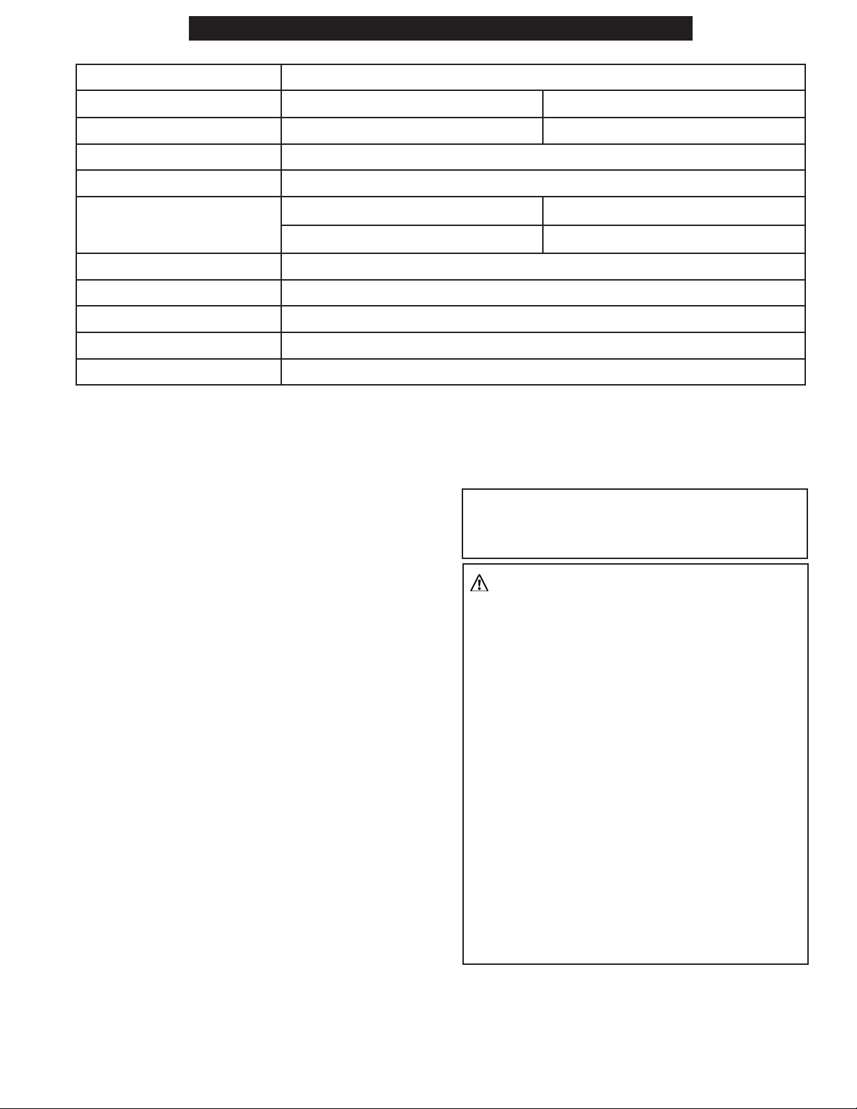
SPECIFICATIONS
Heat Input (Max) (kBTU/hr) 399
Fuel Types Natural Gas (NG)
Propane (LP)
Fuel Consumption 0.4 MCF (NG) 18.53 lb./hr (LP)
Heating Area (Sq. Ft.) 9,875
CFM Output/Static Pressure 4,032/1.08” WC
Inlet Pressure Minimum: 7” WC Minimum: 11” WC
Maximum: 10” WC Maximum: 14” WC
Outlet Pressure 3.5” WC
Max. Outlet Temperature 257˚F
Power Supply 1 Phase, 120V, 60Hz, 13.4A
Dimensions (L” x W” x H”)
68 x 27 x 60
Dry Weight (lb) 406
If you need assistance or heater information such as a instructions manuals, labels, etc. contact the
manufacturer.
CLEARANCES TO COMBUSTIBLES
Clearances between these HEATSTAR PRO
indirect heaters and adjacent combustible
material (which is part of the building or its
contents) shall not be less than:
Top: 5ft (1.5m)
Sides: 5ft (1.5m)
Front: 8.5ft (2.5m)
Back: 5ft (1.5m)
PRECAUTIONS
Caution: When using Thermostat, heater
can start unexpectedly. Turn heater off when
unattended.
WARNING:
• Do not use to heat homes or residential
buildings; for use in public buildings, refer
to national regulations.
• This heater is not suitable for use by
THEORY OF OPERATION
By opening the supply circuit, the gas arrives to
the pressurised nozzle, where it is nebulised and
mixed to the combustive air in the combustion
chamber. A spark triggers combustion while the
exhaust fumes are expelled from the chimney. A
series of sensors constantly checks the correct
operation of the heater, stopping the cycle in the
case of a fault. The fan, located at the rear of the
heater, cools the combustion chamber and the
flue gas pass, transferring heat from the latter
into the environment.
persons (including children) with redu-
ced physical, sensory or mental capacities
or with lack of experience or knowledge
unless supervised by a person responsible
for their safety. Children must be
supervised to make sure they do not play
with the heater. Keep animals at a safe
distance from the heater.
• Improper use of this heater may cause
damage or endanger the life of people,
injuries, burns, explosions, electric shock
or poisoning. The first symptoms of
suffocation by carbon monoxide are similar
to those of flu with headache, light-
Portable Indirect Natural Gas/ Propane Heaters
Installation Instructions and Owner’s Manual
3
Page 4

NEVER LEAVE THE HEATER UNATTENDED WHILE BURNING!NEVER LEAVE THE HEATER UNATTENDED WHILE BURNING!NEVER LEAVE THE HEATER UNATTENDED WHILE BURNING!
headedness and/or nausea. These symptoms
could be caused by the faulty functioning of
the heater. IF THESE SYMPTOMS OCCUR,
GO OUTDOORS IMMEDIATELY and have the
heater repaired by technical support.
• All cleaning, maintenance and repair
operations that involve access to dangerous
parts (such as replacing a damaged
power cable) must be performed by the
manufacturer, by their technical support
centre, or by a person with a similar
qualification, in order to prevent any risk,
even if disconnection from the mains is
required.
Please observe the following precautions
when operating your HEATSTAR product.
1. The manufacturer declines any liability for
damage to property/persons deriving from
improper use of the heater.
2. Comply with all local laws and regulations in
force when using the heater.
3. For correct use of the heater and to preserve
the fuel, follow all local laws and the
regulations in force.
4. Fuel tanks must be kept at a minimum
distance from the heater, in accordance with
current standards.
5. Check that the firefighting equipment is
available and suitable to the potential of the
heater.
6. The appliance must only be used as a
hot air heater (heating mode) or fan
(ventilation mode, for models that include
this functionality). Follow these instructions
scrupulously.
7. Only power the heater by using the type
of fuel expressly specified and with current
having the voltage and frequency indicated
on the data plate applied on the heater.
8. The electric power line of the heater must be
equipped with an grounding system, residual
current device, and cut-off switch.
9. Check correct grounding.
10. Only use extensions with suitable section,
with grounding wire.
11. The heater must function on a levelled, stable
and fire-proof surface, in order to prevent fire
hazards.
12. It is strictly prohibited to use the appliance in
basements or rooms below ground level.
13. Never handle or conduct maintenance on
the heater when it is hot, connected to the
power supply or in operation.
14. Keep animals at a safe distance from the
heater.
15. Only use in well-ventilated areas. Set-up
a suitable opening in line with current
standards, with the purpose of introducing
fresh air from outdoors.
16. Never use the heater in frequently used
rooms, camping vans, caravans, motorhomes.
17. The heater must not be used in places where
explosive dusts, fumes, gases, fuels, solvents,
paints or other highly flammable vapours are
present.
18. Recommended safety distances between
the heater and flammable substances: front
output 2.5 m (8.5 ft.); on the side, at the top
and at the back = 1.5 m (5 ft.).
19. Heaters used near tarpaulins, curtains or
other similar covering materilas must be kept
at a safe distance. It is advised to use fire-
proof covering material.
20. If the power supply cable is damaged, it
must be replaced by an authorized technical
support center to prevent any risk.
21. The air vent (rear side) and/or the air outlet
vent (front side) cannot be totally or partially
obstructed for any reason.
22. Only use original kits to direct the air coming
in and/or going out (where applicable).
23. If the heater does not switch on or switch-on
is faulty, consult the “TROUBLESHOOTING”
section.
24. The heater must never be moved, handled
or subjected to any maintenance operations
while running.
25. In any condition of use or non-use of the
appliance, make sure that the flexible gas
hose is not damaged (crushed, bent, twisted,
taut).
Portable Indirect Natural Gas/ Propane Heaters
Installation Instructions and Owner’s Manual
4
Page 5
NEVER LEAVE THE HEATER UNATTENDED WHILE BURNING!NEVER LEAVE THE HEATER UNATTENDED WHILE BURNING!NEVER LEAVE THE HEATER UNATTENDED WHILE BURNING!
26. If the smell of gas is perceived, switch the
appliance off immediately, close the gas
cylinder, disconnect the mains plug and then
contact technical support.
27. When it is controlled by a thermostat, the
heater can turn on at any time.
28. When it is not used, disconnect the heater
from the mains plug, close the gas supply,
disconnect the gas hose from the heater and
plug the gas inlet on the heater.
29. Use original spare parts when replacing the
burner, strictly complying with indications
regarding capacity, type of nozzles and pump
pressure. An increase in burner power could
damage the heater.
30. Only use a soft cloth to clean the heater (do
not use detergents). Do not use water for this
operation.
31. Ask the technical support service to check
that the heater is working properly at least
once a year and/or as required.
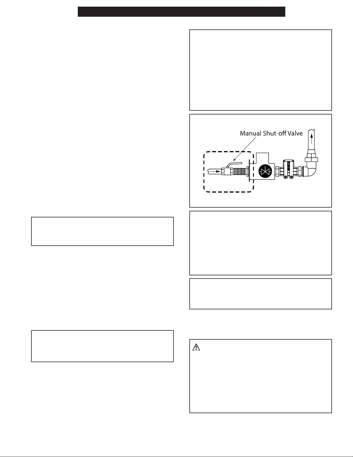
GAS SUPPLY CONNECTION
CAUTION: Gas supply connection to the
manifold installed on the heater must only
be performed by qualified personnel and in
compliance with local laws. Pipes and valves
of appropriate section must be used. We
recommend using a manual shut-off valve
and a flexible joint to be positioned between
the gas manifold and main supply piping.
Refer to Figure 1.
FIGURE 1
UNPACKING
WARNING: The packaging material is not a
toy. Keep the plastic bag out of the reach of
children; danger of suffocation!
1. Remove all protective material which may
have been applied to the heater for shipment.
2. The heater is placed on a platform. Lift it
delicately using hooks and chains. Use the
holes on the structure to lift the heater.
3. Check the heater for possible shipping
damage. If any damage is found immediately
contact the manufacturer at 866-447-2194.
UNIT INSTALLATION
WARNING: Closely follow all the operations
described in this paragraph. Installation must
only be carried out by qualified personnel.
CAUTION: If the heater is connected to
natural gas, installation must be compliant
with local laws and, in case of no specific
regulations, refer to the national regulation
on gas fuel ANSI Z223.1/NFPA 54 and to
the natural gas and propane gas installation
regulation CSAB149.1.
CAUTION: Before any switch-on, make sure
the heater is correctly configured. Gas supply
must be in line with the heater configuration.
IF PROPANE GAS (L.P.G.) IS CONNECTED BY
USING A SUPPLY CYLINDER, STRICTLY COMPLY
WITH THE FOLLOWING:
WARNING:
• INSTALLATION MUST BE COMPLIANT
WITH LOCAL LAWS AND, IN CASE OF
NO SPECIFIC REGULATIONS, REFER TO
THE NATIONAL REGULATION ON GAS
FUEL ANSI Z223.1/NFPA 54 AND TO
THE NATURAL GAS AND PROPANE GAS
INSTALLATION REGULATION CSAB149.1.
Portable Indirect Natural Gas/ Propane Heaters
Installation Instructions and Owner’s Manual
5
Page 6
NEVER LEAVE THE HEATER UNATTENDED WHILE BURNING!NEVER LEAVE THE HEATER UNATTENDED WHILE BURNING!NEVER LEAVE THE HEATER UNATTENDED WHILE BURNING!
Circuit
• 5.1.2. TO DETERMINE THE SUPPLY
CYLINDER CAPACITY, WE RECOMMEND
CONSULTING YOUR PROPANE GAS
(L.P.G.) SUPPLIER AND USING QUALIFIED
PERSONNEL.
• 5.1.3. WHEN THE HEATER IS NOT BEING
USED, ALWAYS CLOSE THE GAS SUPPLY
BY USING THE SPECIFIC VALVES. THE
GAS CYLINDER MUST ALSO BE CLOSED,
DISCONNECTED AND STORED IN A
SAFE LOCATION ACCORDING TO THE
STANDARDS AND REGULATIONS IN FORCE,
SAFE FROM POSSIBLE RISKS.
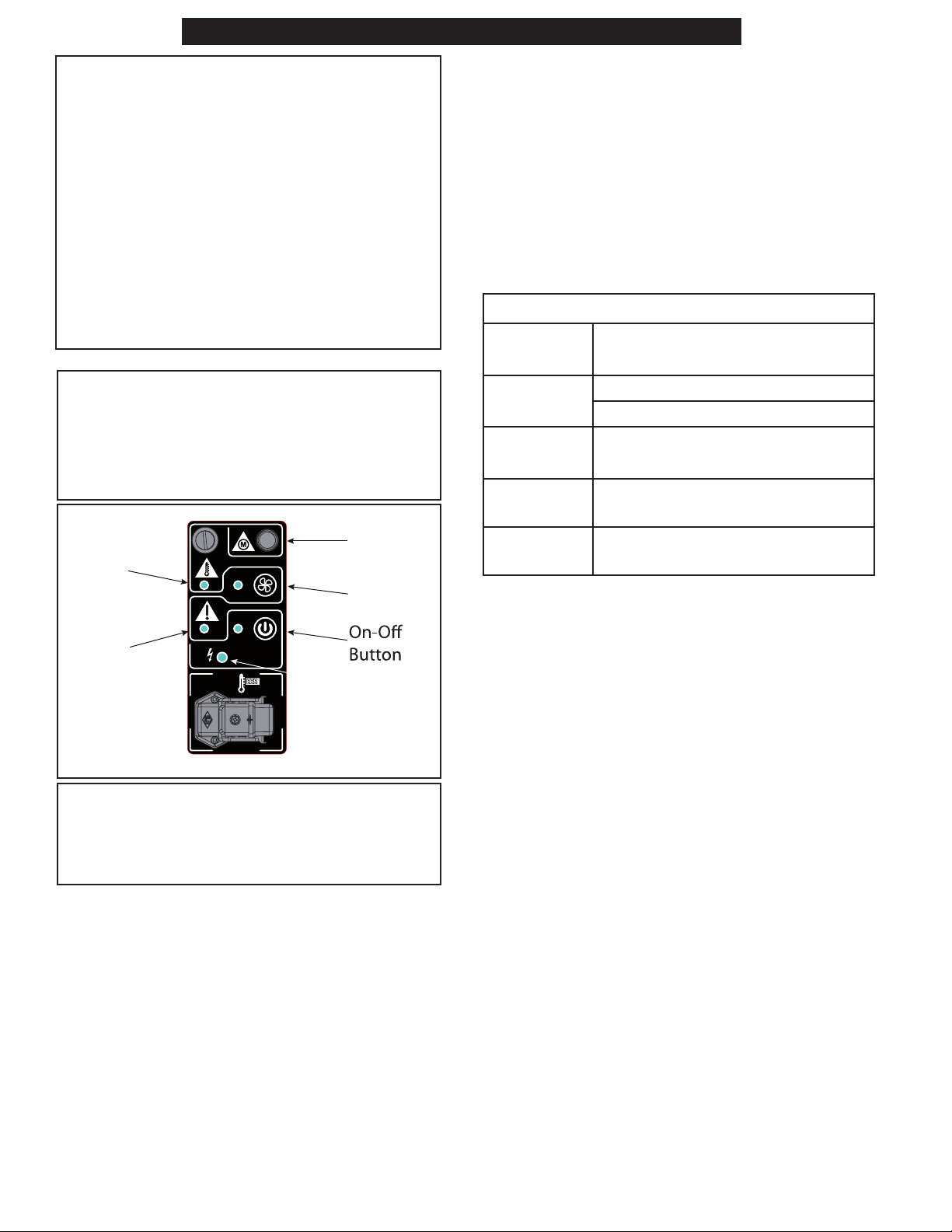
ELECTRIC AL CONNECTION
WARNING: When you connect the power
supply plug, check the light lamp with “spark
icon”. See Figure 2. In case the lamp stays
OFF, you must remove the plug, rotate it
180° and reconnect.
Safety
Thermostat
Light
Breaker
Reset
Fan
Button
Burner
Reset
Light
FIGURE 2
Light Lamp
CAUTION: The electric power line of the
heater must be equipped with an grounding
system, residual current device, and cut-off
switch.
DUCT ADAPTERS
The heater comes with a dual 12” duct adapter
attached. A single 16” duct adapter is available
as an additional accessory as shown in Table 1
below.
ADDITIONAL ACCESSORIES
Table 1 details additional accessories approved
for use with the heater. Instructions for assembly
and operation of accessories are included in
accessory’s packaging.
TABLE 1: ADDITIONAL ACCESSORIES CHART
Description Part Number
Air Recycle
Kit
Digital
Thermostat
Analog
Thermostat
Single Duct
Adapter 16”
F105128 24”x25’ Duct & 24” Clamp
F105127 Adapter Ring
F105106
F105108
F 10512 6
FLUE GAS EXHAUST CONNECTION
Thermal efficiency and correct operation of the
heater are directly linked to the correct draught of
the flue gas exhaust chimney. It is recommended
not to make elbows, which may get clogged, or
reductions in the cross-section of the flue gas
exhaust chimney. If the heater is not connected to
an external flue gas exhaust chimney, it must be
provided with an essentially vertical steel flue gas
exhaust and a draught regulator, respecting the
specifications provided in this technical manual.
The standard supply of the heater includes
all the control and safety devices essential for
its proper operation: electric panel, burner,
manually reset safety thermostat are already
connected.
During installation, prepare the power supply
connection with cables having an appropriate
cross-section in compliance with national
standards in force and the technical data label
applied to the heater.
NOTE: CHECK THE ELECTRIC CONNECTIONS
BEFORE STARTING THE HEATER.
Portable Indirect Natural Gas/ Propane Heaters
Installation Instructions and Owner’s Manual
6
Page 7
NEVER LEAVE THE HEATER UNATTENDED WHILE BURNING!NEVER LEAVE THE HEATER UNATTENDED WHILE BURNING!NEVER LEAVE THE HEATER UNATTENDED WHILE BURNING!
WARNING: In case of gas supply circuit pres-
sure test, it is required to close the manual closing valve, isolating the heater and gas manifold
from the rest of the system.
HEATER CONFIGURATION
The heater is pre-set by the manufacturer, and the
configuration is shown on the data label applied
on the product. The heater may be configured to
operate with propane gas (L.P.G.) or natural gas.
The manual gas selection valve is used to select
the correct gas supply configuration. Rotating
the manual gas selection valve by 90°degrees
changes from natural gas to propane gas (L.P.G.)
and vice-versa. The manual gas selection valve
is normally locked by a safety device, in order to
prevent accidental tampering. This safety device
must be removed by qualified personnel, strictly
following the instructions provided in this manual.
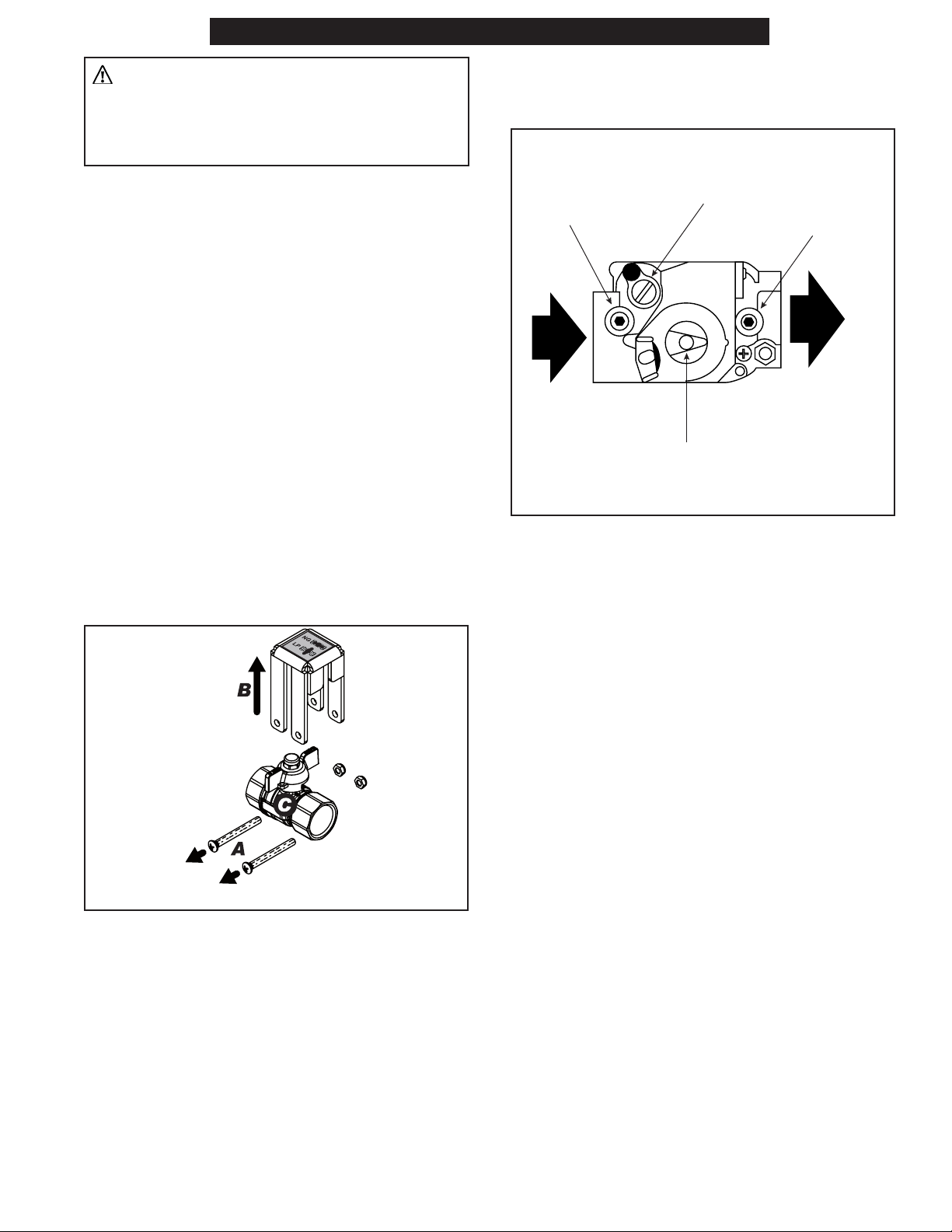
To rotate the manual gas selection valve knob,
follow the steps below:
1. Unscrew and remove the two screws (A)
locking the valve fastening and remove the
safety device. See Figure 3.
1. Unscrew the screw outlet gas pressure
collection point and connect an appropriate
pressure gauge. See Figure 4.
Inlet Gas
Pressure
Collection
Point
Gas Pressure
Adjustment Screw
Outlet Gas
Pressure
Collection
Point
Manual Gas Opening
& Closing Knob
FIGURE 4
2. Rotate the gas pressure adjustment screw
until obtaining the value of 3.5” W.C..
3. Remove the pressure gauge and retighten the
outlet gas pressure collection point screw,
making sure there are no gas leaks.
FIGURE 3
2. Select the type of gas desired by rotating the
knob by 90 degrees.
3. Replace the safety device and fasten with the
screws removed earlier.
If required, check the correct burner gas supply
pressure:
OPERATION
BEFORE SWITCHING HEATER ON
Before any attempt of starting the heater
is made, familiarize yourself with warnings,
specifications and precautions page 2 - 5.
• Check that minimum safety clearances from
combustibles, listed in “CLEARANCES TO
COMBUSTIBLES” on page 3, is achieved in
all directions.
• Make sure that flue gas is adequately ventilated
from the chimney.
• Attach a duct to the outlet if directed venting
of output clean hot air is desired. Ducting can
be installed with the specific clamp or quick
coupling. Refer to “ACCESSORY CHART” on
page 20 for the correct Duct adapter.
• Check that your electrical supply and any
extension cable can meet the requirements
listed in the specifications table.
Portable Indirect Natural Gas/ Propane Heaters
Installation Instructions and Owner’s Manual
7
Page 8

NEVER LEAVE THE HEATER UNATTENDED WHILE BURNING!NEVER LEAVE THE HEATER UNATTENDED WHILE BURNING!NEVER LEAVE THE HEATER UNATTENDED WHILE BURNING!
SWITCH-ON
1. Check the presence of gas inside the supply
circuit.
2. Connect the heater to the electrical supply.
3. Adjust the air damper of the burner according
to your needs. See Figure 5.
RESETTING THE HEATER
The appliance stops when an anomaly occurs.
RESETTING THE BURNER: If the burner is blocked,
the indicator light on the control panel turns on.
Refer to Figure 2. Identify and remove the cause
of the block. To reactivate the burner, press the
reset button on it for at least 10 seconds. See
Figure 6.
Burner
Reset
Button
FIGURE 5
START-UP IN HEATING MODE
Press the on-off button (the burner starts first
and after about one minute ventilation starts).
Refer to the Control Panel in Figure 2.
NOTE: THE HEATER HAS A SENSOR THAT
CONSTANTLY MONITORS THE OUTLET AIR
TEMPERATURE [FOR NORMAL OPERATION, THE
OUTLET AIR TEMPERATURE MUST BE BELOW
125˚C (257˚F). IF THE OUTLET AIR TEMPERATURE
EXCEEDS 125˚C (257˚F), THE HEATER TURNS OFF
THE BURNER AND REACTIVATES COMBUSTION
AFTER A FEW SECONDS.
START-UP IN VENTILATION MODE
Press the fan button. See Figure 2.
SWITCHING OFF THE HEATER:
IMPORTANT: Never unplug the heater to
switch it off or before it is completely off.
The heater turns off by pressing the “OFF”
button. The burner box will turn off, and the fan
will continue running to cool off the burner box.
Do not unplug the heater until this cooling
cycle has totally ended. When the outlet air
temperature drops below 50˚C (122˚F), the fan
turns off and the luminous signal of the button
turns on to indicate the presence of voltage
(stand-by condition).
FIGURE 6
RESETTING THE SAFETY THERMOSTAT: Safety
thermostat operation is identified by an indicator
light. Refer to Figure 2. Identify and remove the
cause that triggered the safety thermostat. Press
the reset button located at the back of the heater
all the way.
RESETTING THE CIRCUIT BREAKER: Identify and
remove the cause of activation of the circuit
breaker. Press the reset button to release it. See
Figure 2.
THE EXTERNAL THERMOSTAT SOCKET
The heater can only work automatically when a
control device, such as a thermostat or a timer,
is connected to the heater. F105106, a 33ft
digital Thermostat, and F105108, a 33ft analog
thermostat are both approved for use by the
manufacturer with the heater. Connection to
the heater is made by removing the thermostat
socket cap and connecting the room thermostat
to the socket. If no room thermostat will be
connected the cap must be inserted into the
socket.
Portable Indirect Natural Gas/ Propane Heaters
Installation Instructions and Owner’s Manual
8
Page 9

NEVER LEAVE THE HEATER UNATTENDED WHILE BURNING!NEVER LEAVE THE HEATER UNATTENDED WHILE BURNING!NEVER LEAVE THE HEATER UNATTENDED WHILE BURNING!
TRANSPORTATION
Before any handling, the heater must be switched
off following the proper procedure on page 8,
and disconnected from the electrical and gas
supply. Wait for the heater to cool.
Before handling, make sure that the support
used to move the heater is capable of bearing its
weight (the weight is displayed on the technical
specification of the appliance). Do not attempt to
lift or move the heater without the aid of suitable
equipment (this operation must be carried out
with the utmost attention to avoid personal harm
or damage to the heater).
STORAGE
IN ORDER TO KEEP THE HEATER IN THE BEST
POSSIBLE CONDITIONS, WE RECOMMEND
FOLLOWING THE PROCEDURE BELOW:
• Place the heater in a dry place away from
potential external damage.
FIGURE 7
2. Remove the plates, which close the inspection
openings, by removing the screws. See Figure
8.
Screw
Inspection Opening
MAINTENANCE
WARNING:
Never service heater while it is plugged in,
operating or hot. Severe burns or electrical
shock can occur.
Periodic maintenance is recommended to keep
the heater in good condition, avoiding possible
failures or faults as far as possible.
CLEANING THE FAN
Use compressed air for routine cleaning of the
fan, blowing the air through the rear grille.
CLEANING THE BURNER
Read and understand the specific manual to clean
the burner.
CLEANING THE COMBUSTION CHAMBER
It is recommended to clean the combustion
chamber and flue gas duct at least once a
year or when required to avoid problems
regarding chimney draught and combustion. The
combustion chamber is cleaned through the five
inspection openings on the front of the heater.
Closely follow this sequence to perform cleaning
(keep the screws and washers with care):
1. Remove the air ducting cone by removing
the screws which secure it to the heater. See
Figure 7.
Portable Indirect Natural Gas/ Propane Heaters
Gasket
FIGURE 8
3. Remove the gaskets installed and do not reuse
them. Only use new and original gaskets. See
Figure 11.
4. Spray high pressure water inside the chamber
through the inspection openings. Refer to
Figure 11. When washing, move the nozzle in
various positions so the water reaches all the
slots of the combustion chamber.
5. Lift the combustion chamber from the back
to empty as much water as possible from
inside the chamber (this operation must be
carried out with the utmost attention to avoid
personal harm or damaging the heater).
6. Reassemble the heater performing the
sequence of operations in the opposite order,
replacing the gaskets with original spare
parts.
NOTE: BEFORE SWITCHING THE HEATER BACK
ON, MAKE SURE AS MUCH WATER AS POSSIBLE
HAS BEEN ELIMINATED FROM INSIDE THE
COMBUSTION CHAMBER TO AVOID SERIOUS
DAMAGE.
Installation Instructions and Owner’s Manual
9
Page 10

NEVER LEAVE THE HEATER UNATTENDED WHILE BURNING!NEVER LEAVE THE HEATER UNATTENDED WHILE BURNING!NEVER LEAVE THE HEATER UNATTENDED WHILE BURNING!
WARNING: BEFORE STARTING ANY MAINTENANCE OR REPAIRS, DISCONNECT THE POWER CABLE
AND MAKE SURE THAT THE HEATER IS COLD.
TABLE 4: PREVENTATIVE MAINTENANCE SCHEDULE
COMPONENT MAINTENANCE FREQUENCY MAINTENANCE PROCEDURE
Safety
Yearly check and/or when required
Thermostat
Nozzle Replace yearly and/or when required
Electrical
Yearly check and/or when required
System
Fan Yearly check and/or when required
Motor Yearly check and/or when required
Combustion
Yearly check and/or when required
chamber
TROUBLESHOOTING
OBSERVED
SYMPTOM
The heater
does not
start or
does not
remain on
The heater
generates
smoke
during
operation
The heater
does not
turn off
POSSIBLE CAUSE REMEDY
No power supply • Check that there is electric power
• Check that the heater is connected to the correct power supply
• Contact an authorized technical support center or HEATSTAR
customer service
Interrupted power cable • Contact an authorized technical support center or HEATSTAR
customer service
Electronics need to be reset or are faulty • Reset the heater
• Contact an authorized technical support center or HEATSTAR
customer service
Incorrect setting of the room thermostat
(if applicable)
No gas supply • Check that there is gas supply
Foreign substances in the fuel system • Contact an authorized technical support center or HEATSTAR
Foreign substances in the fuel system • Contact an authorized technical support center or HEATSTAR
Obstructed inlet air vent
Faulty electronic system
• Set the room thermostat to a temperature higher than the tem-
perature of the working environment
• Correct the gas supply setting
customer service
customer service
• Remove all possible obstructions from the rear grille
• Contact an authorized technical support center or HEATSTAR
customer service
Contact a technical service center.
Service of these components
should only be performed by a
qualified serviceman. Qualified
service professionals may contact
the manufacturer for a service
manual.
PARTS ORDERING INFORMATION:
PURCHASING: Accessories may be purchased at any HEAT STAR local dealer or direct from the factory
FOR INFORMATION REGARDING SERVICE
Please call Toll-Free 866-447-2194 • www.heatstarbyenerco.com
Our office hours are 8:00 AM – 5:00 PM, EST, Monday
through Friday. Please include the model number, date of purchase, and description of problem in all communication.
Portable Indirect Natural Gas/ Propane Heaters
Installation Instructions and Owner’s Manual
10
Page 11

NEVER LEAVE THE HEATER UNATTENDED WHILE BURNING!NEVER LEAVE THE HEATER UNATTENDED WHILE BURNING!NEVER LEAVE THE HEATER UNATTENDED WHILE BURNING!
**PAGE LEFT INTENTIONALLY BLANK**
Portable Indirect Natural Gas/ Propane Heaters
Installation Instructions and Owner’s Manual
11
Page 12

NEVER LEAVE THE HEATER UNATTENDED WHILE BURNING!NEVER LEAVE THE HEATER UNATTENDED WHILE BURNING!NEVER LEAVE THE HEATER UNATTENDED WHILE BURNING!
PARTS LIST AND DIAGRAM
PARTS LIST AND DIAGRAM
HSP400ID-G
11
9
8
12
13
14
16
15
10
7
20
5
4
B
6
17
21
1
Portable Indirect Natural Gas/ Propane Heaters
3
22
23
22
24
25
2
Installation Instructions and Owner’s Manual
12
19
18
26
27
Page 13

NEVER LEAVE THE HEATER UNATTENDED WHILE BURNING!NEVER LEAVE THE HEATER UNATTENDED WHILE BURNING!NEVER LEAVE THE HEATER UNATTENDED WHILE BURNING!
PARTS LIST AND DIAGRAM
PARTS LIST AND DIAGRAM
HSP400ID-G
# P/N PART DESCRIPTION
1 51328 MOTOR
2 51329 MOTOR POWER CORD
3 5127 8 FAN
4 5133 4 FIBER ROPE GASKET
5 51335 FLANGE
6 51336 COVER
7 51337 BARREL GASKET
8 5133 8 BARREL FLANGE
9 51339 SCREW
10 513 4 0 DUCT ADAPTER
11 513 41 OUTER SHELL
12 5111 0 T-STAT HOUSING
13 513 4 3 CLIP
14 513 4 4 CLIP
15 510 9 6 T-STAT AND WIRE
16 5135 0 NTC SENSOR WIRE
17 513 5 3 BURNER POWER CORD
18 5127 9 BURNER
19 512 8 0 BURNER HEAD
20 51356 COMPENSATION FLANGE
21 513 5 7 90˚°GAS CONNECTION
22 5135 8 STRAIGHT GAS CONNECTION
23 51359 GAS SELECTION VALVE
24 513 6 0 GAS VALVE
25 513 61 GAS VALVE BRACKET
26 51460 LP/NG BRACKET
27 514 61 GAS VALVE POWER CORD
NOTE: Not all parts available. For questions contact manufacturer.
WARNING: Failure to position the parts in accordance with these diagrams or failure to use only
parts specifically approved with this heater may result in property damage or personal injury.
Portable Indirect Natural Gas/ Propane Heaters
Installation Instructions and Owner’s Manual
13
Page 14

NEVER LEAVE THE HEATER UNATTENDED WHILE BURNING!NEVER LEAVE THE HEATER UNATTENDED WHILE BURNING!NEVER LEAVE THE HEATER UNATTENDED WHILE BURNING!
PARTS LIST AND DIAGRAM
PARTS LIST AND DIAGRAM
HSP400ID-G (Sub-Assembly B)
18
17
9
16
14
15
B
2
8
10
11
12
13
7
6
5
4
3
Portable Indirect Natural Gas/ Propane Heaters
1
Installation Instructions and Owner’s Manual
14
Page 15

NEVER LEAVE THE HEATER UNATTENDED WHILE BURNING!NEVER LEAVE THE HEATER UNATTENDED WHILE BURNING!NEVER LEAVE THE HEATER UNATTENDED WHILE BURNING!
PARTS LIST AND DIAGRAM
PARTS LIST AND DIAGRAM
HSP400ID-G (Sub-Assembly B)
# P/N PART DESCRIPTION
1 5136 3 PC BOARD
2 510 8 3 RELAY
3 5136 8 LED PC BOARD
4 5136 9 LED PC BOARD WIRES
5 5137 0 ROOM T-STAT WIRES
6 5111 4 SAFETY THERMOSTAT
7 51138 TERMINAL BLOCK
8 51374 AUTOMATIC SWITCH
9 5137 6 BURNER WIRES
10 5137 7 90˚ SOCKET
11 5111 9 THERMOSTAT RESET CAP
12 5137 9 LIGHT CAP
13 5119 0 THERMOSTAT SOCKET
14 5119 3 THERMOSTAT CAP
15 511 9 1 PLUG,ROOM,TSTAT
16 513 8 5 POWER CORD
17 513 8 9 WIRES FOR MOTOR
18 513 9 0 SOCKET
NOTE: Not all parts available. For questions contact manufacturer.
WARNING: Failure to position the parts in accordance with these diagrams or failure to use only
parts specifically approved with this heater may result in property damage or personal injury.
Portable Indirect Natural Gas/ Propane Heaters
Installation Instructions and Owner’s Manual
15
Page 16

NEVER LEAVE THE HEATER UNATTENDED WHILE BURNING!NEVER LEAVE THE HEATER UNATTENDED WHILE BURNING!NEVER LEAVE THE HEATER UNATTENDED WHILE BURNING!
PARTS LIST AND DIAGRAM
PARTS LIST AND DIAGRAM
HSP400ID-G
1
2
3
5
7
4
5
6
4
3
Portable Indirect Natural Gas/ Propane Heaters
1
2
8
Installation Instructions and Owner’s Manual
16
Page 17

NEVER LEAVE THE HEATER UNATTENDED WHILE BURNING!NEVER LEAVE THE HEATER UNATTENDED WHILE BURNING!NEVER LEAVE THE HEATER UNATTENDED WHILE BURNING!
PARTS LIST AND DIAGRAM
PARTS LIST AND DIAGRAM
HSP400ID-G
# P/N PART DESCRIPTION
1 513 91 COTTER PIN
2 513 92 WHEEL WASHER
3 5112 8 PNEUMATIC WHEEL
4 510 91 WHEEL BUSHING
5 514 6 2 LIFTING ARC FOOT
6 514 6 3 LIFTING ARC
7 51090 WHEEL AXLE
8 510 8 6 HANDLE
NOTE: Not all parts available. For questions contact manufacturer.
WARNING: Failure to position the parts in accordance with these diagrams or failure to use only
parts specifically approved with this heater may result in property damage or personal injury.
Portable Indirect Natural Gas/ Propane Heaters
Installation Instructions and Owner’s Manual
17
Page 18

NEVER LEAVE THE HEATER UNATTENDED WHILE BURNING!NEVER LEAVE THE HEATER UNATTENDED WHILE BURNING!NEVER LEAVE THE HEATER UNATTENDED WHILE BURNING!
PARTS LIST AND DIAGRAM
PARTS LIST AND DIAGRAM
HSP400ID-G
12
16
13
17
18
14
15
7
3
5
8
6
9
10
11
1
Portable Indirect Natural Gas/ Propane Heaters
4
2
Installation Instructions and Owner’s Manual
18
Page 19

NEVER LEAVE THE HEATER UNATTENDED WHILE BURNING!NEVER LEAVE THE HEATER UNATTENDED WHILE BURNING!NEVER LEAVE THE HEATER UNATTENDED WHILE BURNING!
PARTS LIST AND DIAGRAM
PARTS LIST AND DIAGRAM
HSP400ID-G
# P/N PART DESCRIPTION
1 51262 BURNER BACK COVER
2 513 0 2 AIR PRESSURE SWITCH
3 513 0 3 PRIMARY CONTROL BOX
4 5133 0 CONTROL BOX BASE
5 51332 120/24 VOLT TRANSFORMER
6 513 4 2 AIR SWITCH TUBE & CONNECTOR
7 513 4 9 IONIZATION LEAD
8 51355 CHASSIS MOUNTING COLLAR
9 51371 FAN
10 5137 2 COMPACITOR
11 5137 3 MOTOR
12 5137 8 MOUNTING GASKET
13 5153 8 MOUNTING FLANGE
14 515 3 9 HEAD ASSEMBLY
15 51540 ELECTRODE
16 513 8 2 PROBE
17 514 03 DIFFUSER
18 514 0 4 DISTRIBUTOR DIFFUSER DISK
NOTE: Not all parts available. For questions contact manufacturer.
WARNING: Failure to position the parts in accordance with these diagrams or failure to use only
parts specifically approved with this heater may result in property damage or personal injury.
Portable Indirect Natural Gas/ Propane Heaters
Installation Instructions and Owner’s Manual
19
Page 20

NEVER LEAVE THE HEATER UNATTENDED WHILE BURNING!NEVER LEAVE THE HEATER UNATTENDED WHILE BURNING!NEVER LEAVE THE HEATER UNATTENDED WHILE BURNING!
PARTS LIST: ACCESSORY CHART
PART # DESCRIPTION
F 10512 6 16" Single Duct adapter
F150040 Flex Heat Duct 12” x 25’
F150050 Flex Heat Duct 16” x 25’
F 105127 Adapter Ring for Air Recycling System
F 10512 8 24” x 25’ Duct & 24” Clamp for Air Recycling System
F105106 Digital Thermostat 33 ft
F105108 Remote Analog Thermostat 33 ft
PARTS ORDERING INFORMATION:
PURCHASING: Accessories may be purchased at any HEAT STAR local dealer or direct from the factory
FOR INFORMATION REGARDING SERVICE
Please call Toll-Free 866-447-2194 • www.heatstarbyenerco.com
Our office hours are 8:00 AM – 5:00 PM, EST, Monday
through Friday. Please include the model number, date of purchase, and description of problem in all
communication.
Portable Indirect Natural Gas/ Propane Heaters
Installation Instructions and Owner’s Manual
20
Page 21

NEVER LEAVE THE HEATER UNATTENDED WHILE BURNING!NEVER LEAVE THE HEATER UNATTENDED WHILE BURNING!NEVER LEAVE THE HEATER UNATTENDED WHILE BURNING!
WIRING DIAGRAM
CABLE # TYPE CABLE
1 PHASE
2 NEUTRAL
3 GROUND
4 BURNER PHASE
5 BURNER NEUTRAL
6 BURNER GROUND
7 FAN NEUTRAL
8 FAN GROUND
9 FAN PHASE
10 ELECTRONIC BOARD PHASE
11 ELECTRONIC BOARD NEUTRAL
12 KEYBOARD GROUND
13 KEYBOARD NEUTRAL
14 BURNER SIGNAL LOCK
15 COMMAND ON/OFF
16 KEYBOARD PHASE
17 ALARM LIGHT
18 COMMAND RELAY FAN
19 24VDC
20 THERMOSTAT NEUTRAL
21 THERMOSTAT PHASE
22 THERMOSTAT CONTACT
23 THERMOSTAT GROUND
24 RELAY FAN
25 RELAY FAN
26 PRE HEATER NEUTRAL
27 PRE HEATER PHASE
28 NTC SENSOR
29 NTC SENSOR
Portable Indirect Natural Gas/ Propane Heaters
Installation Instructions and Owner’s Manual
21
Page 22

NEVER LEAVE THE HEATER UNATTENDED WHILE BURNING!NEVER LEAVE THE HEATER UNATTENDED WHILE BURNING!NEVER LEAVE THE HEATER UNATTENDED WHILE BURNING!
OPERATING INSTRUCTIONS
AND OWNER’S MANUAL
MODEL#
HSP400ID-G
READ INSTRUCTIONS CAREFULLY: YOUR SAFETY IS IMPORTANT TO YOU AND TO OTHERS.
Read and follow all instructions. Place instructions in a safe place for future reference. Do not allow
anyone who has not read these instructions to assemble, light, adjust or operate the heater.
WARNING:
USE ONLY MANUFACTURER’S REPLACEMENT PARTS. USE OF ANY OTHER PARTS COULD
CAUSE INJURY OR DEATH. REPLACEMENT PARTS ARE ONLY AVAILABLE DIRECT FROM
THE FACTORY AND MUST BE INSTALLED BY A QUALIFIED SERVICE AGENCY.
REPLACEMENT PARTS ORDERING INFORMATION:
PURCHASING: Accessories may be purchased at any HEATSTAR by Enerco local dealer
or direct from the factory
FOR INFORMATION REGARDING SERVICE
Please call Toll-Free 866-447-2194
WWW.HEATSTARBYENERCO.COM
Our office hours are 8:00 AM – 5:00 PM, EST, Monday through Friday.
Please include the model number, date of purchase, and description of problem in all
communication.
LIMITED WARRANTY
The company warrants this product to be free from imperfections in material or
workmanship, under normal and proper use in accordance with instructions of The
Company, for a period of one year from the date of delivery to the buyer. The Company,
at its option, will repair or replace products returned by the buyer to the factory,
transportation prepaid within said one year period and found by the Company to have
imperfections in material or workmanship.
If a part is damaged or missing, call our Technical Support Department at 866-447-2194.
Address any Warranty Claims to the Service Department, Enerco Group, Inc., 4560 W.
160TH ST., Cleveland, Ohio 44135. Include your name, address, telephone number, serial
number off heater and include details concerning the claim. Also, supply us with the
purchase date and the name and address of the dealer from whom you purchased our
product.
The foregoing is the full extent of the responsibility of the Company. There are no other
warranties, express or implied. Specifically there is no warranty of fitness for a particular
purpose and there is no warranty of merchantability. In no event shall the Company be
liable for delay caused by imperfections, for consequential damages, or for any charges
of the expense of any nature incurred without its written consent. The cost of repair
or replacement shall be the exclusive remedy for any breach of warranty. There is no
warranty against infringement of the like and no implied warranty arising from course
of dealing or usage of trade. This warranty will not apply to any product which has been
repaired or altered outside of the factory in any respect which in our judgment affects
its condition or operation.
Some states do not allow the exclusion or limitation of incidental or consequential
damages, so the above limitation or exclusion may not apply to you. This Warranty gives
you specific legal rights, and you may have other rights which vary from state to state.
Enerco Group, Inc. reserves the right to make changes at any time, without notice or
obligation, in colors, specifications, accessories, materials and models.
ENERCO Technical Products, Inc., 4560 W. 160TH ST., CLEVELAND, OHIO 44135 • 866-447-2194
HEATSTAR is a registered trademarks of ENERCO Technical Products, Inc.
© 2019, ENERCO Technical Products. All rights reserved
Portable Indirect Natural Gas/ Propane Heaters
22
Installation Instructions and Owner’s Manual
 Loading...