

HeatStar HS50K, HS75KT, HS125KT, HS175KT, HS210KT Operating Instructions And Owner's Manual
Page 1
OPERATING INSTRUCTIONS
AND OWNER’S MANUAL
READ INSTRUCTIONS CAREFULLY: Read and follow all instructions. Place instructions in a safe
place for future reference. Do not allow anyone who has not read these instructions to assemble,
light, adjust or operate the heater.
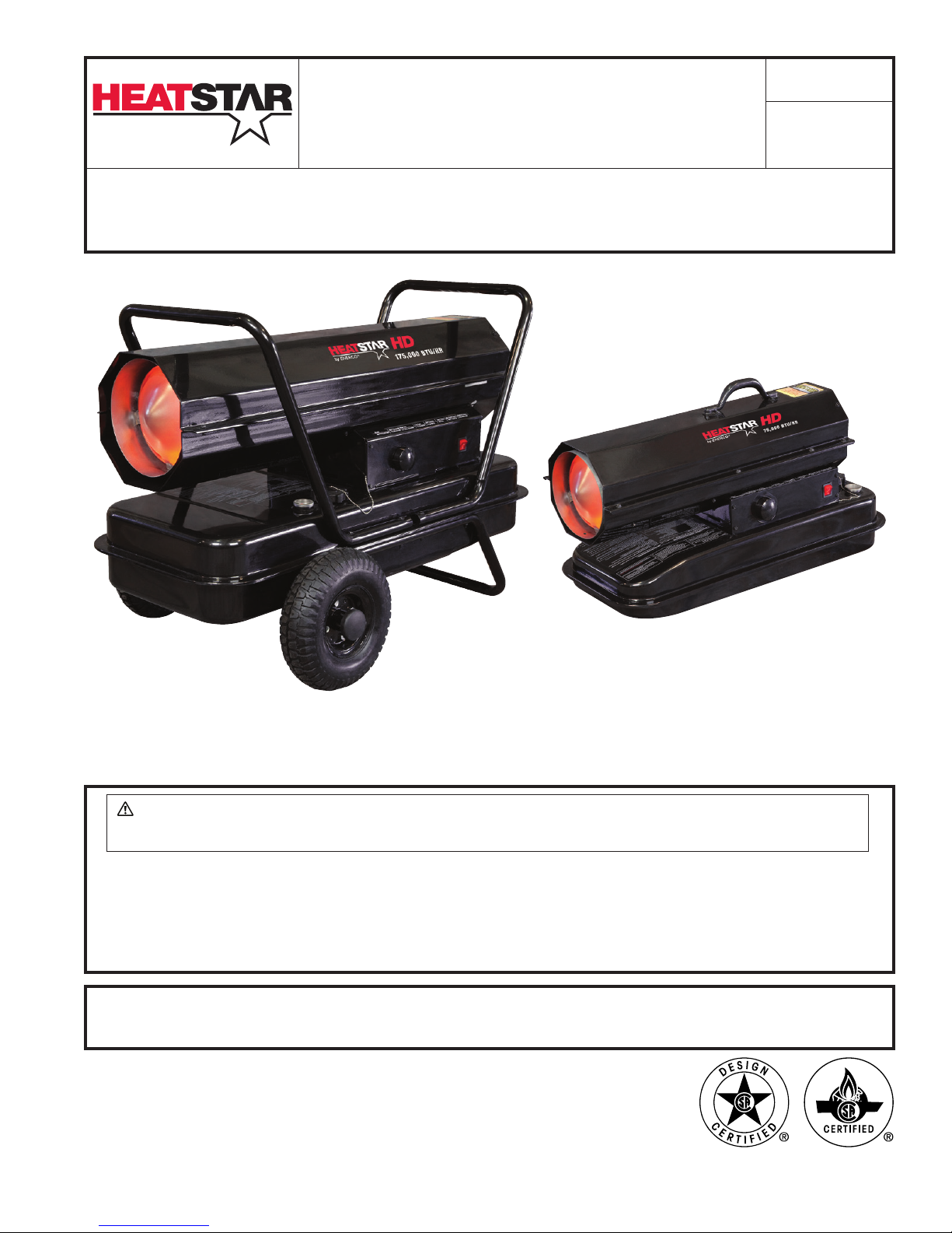
Model #
HS50K, HS75KT,
HS125KT, HS175KT,
HS210KT
KEROSENE
FORCED-AIR HEATER
WARNING: If the information in this manual is not followed exactly, a fire or
explosion may result causing property damage, personal injury or loss of life.
— Do not store or use gasoline or other flammable vapors and liquids in the vicinity of this or any
other appliance.
— Service must be performed by a qualified service agency.
This is an unvented portable heater. It uses air (oxygen) from the area in which it is used. Adequate
combustion and ventilation air must be provided. Refer to page 3.
UL733, CSA B140.8, CSA B140.9.3
HEATSTAR by ENERCO, 4560 W. 160TH ST., CLEVELAND, OHIO 44135 • 866-447-2194
01/15 70204 2015 JM
Page 2
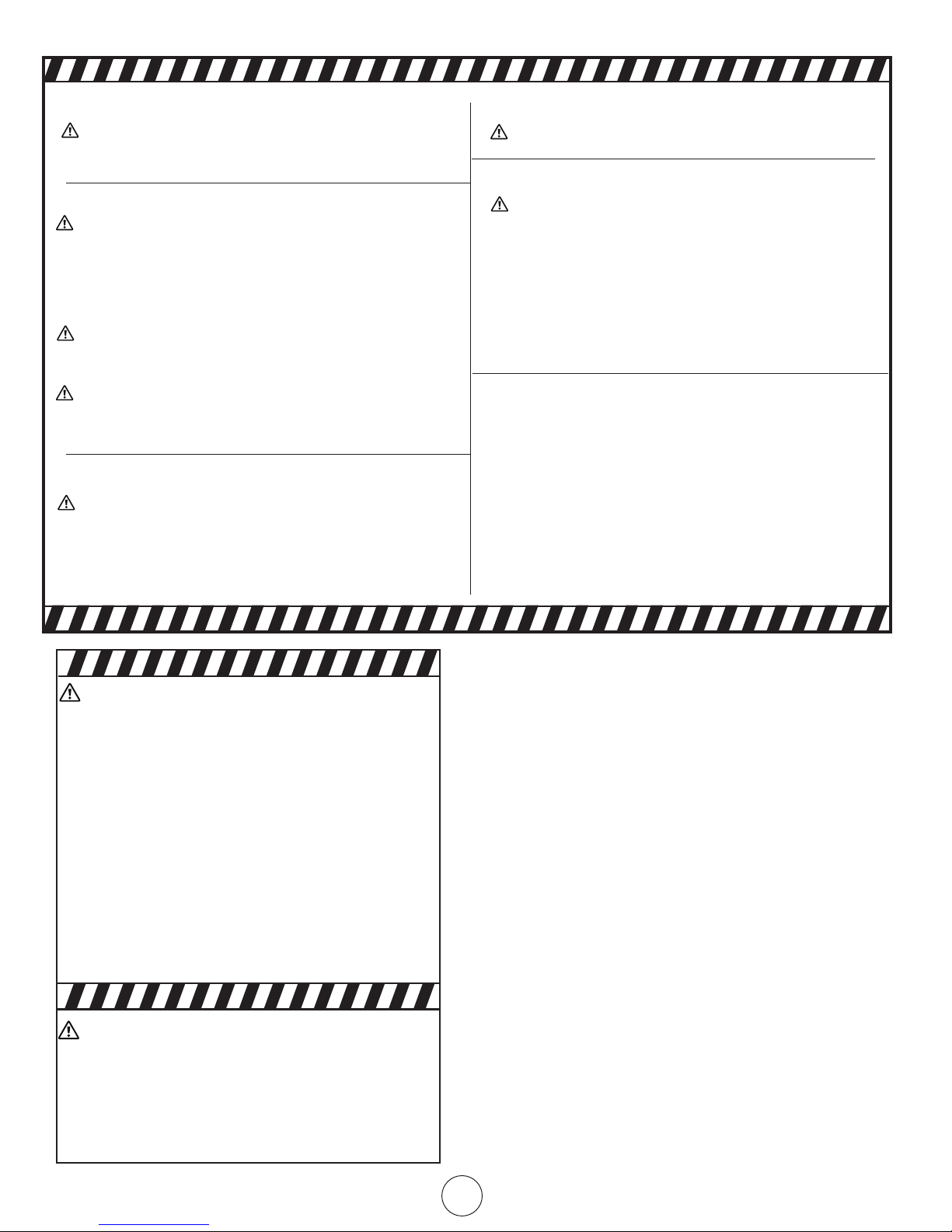
WARNING:
YOUR SAFETY IS IMPORTANT TO YOU AND TO OTHERS,
SO PLEASE READ THESE INSTRUCTIONS BEFORE YOU
OPERATE THIS HEATER.
GENERAL HAZARD WARNING:
FAILURE TO COMPLY WITH THE PRECAUTIONS AND
INSTRUCTIONS PROVIDED WITH THIS HEATER, CAN
RESULT IN DEATH, SERIOUS BODILY INJURY AND
PROPERTY LOSS OR DAMAGE FROM HAZARDS OF FIRE,
EXPLOSION, BURN, ASPHYXIATION, CARBON MONOXIDE POISONING, AND/OR ELECTRICAL SHOCK.
ONLY PERSONS WHO CAN UNDERSTAND AND FOLLOW
THE INSTRUCTIONS SHOULD USE OR SERVICE THIS
HEATER.
IF YOU NEED ASSISTANCE OR HEATER INFORMATION
SUCH AS AN INSTRUCTIONS MANUAL, LABELS, ETC.
CONTACT THE MANUFACTURER.
WARNING:
CARBON MONOXIDE CAN KILL YOU
USING A PORTABLE GAS CAMPING HEATER INSIDE A
TENT, RV, CAMPER, VEHICLE, SHELTER OR OTHER ENCLOSED AREAS CAN PRODUCE DEADLY CARBON MON-
OXIDE
WARNING:
NOT FOR HOME OR RECREATIONAL VEHICLE USE
WARNING:
FIRE, BURN, INHALATION, AND EXPLOSION HAZARD.
KEEP SOLID COMBUSTIBLES, SUCH AS BUILDING
MATERIALS, PAPER OR CARDBOARD, A SAFE DISTANCE
AWAY FROM THE HEATER AS RECOMMENDED BY THE
INSTRUCTIONS NEVER USE THE HEATER IN SPACES
WHICH DO OR MAY CONTAIN VOLATILE OR AIRBORNE
COMBUSTIBLES, OR PRODUCTS SUCH AS GASOLINE,
SOLVENTS, PAINT THINNER, DUST PARTICLES OR UN-
KNOWN CHEMICALS.
WARNING:
The State of California requires the following warning:
COMBUSTION BY-PRODUCTS PRODUCED WHEN USING THIS PRODUCT CONTAIN CARBON MONOXIDE,
A CHEMICAL KNOWN TO THE STATE OF CALIFORNIA
TO CAUSE CANCER AND BIRTH DEFECTS (OR OTHER
REPRODUCTIVE HARM).
THIS PRODUCT CONTAINS CHEMICALS KNOWN TO
THE STATE OF CALIFORNIA TO CAUSE CANCER AND
BIRTH DEFECTS OR OTHER REPRODUCTIVE HARM.
WARNING:
• DO NOT USE GASOLINE, NAPHTHA OR VOLATILE
FUELS.
• STOP HEATER BEFORE ADDING FUELS.
• ALWAYS FILL OUTDOORS AWAY FROM OPEN FLAME
• DO NOT USE EXTERNAL FUEL SOURCE.
• DO NOT OPERATE HEATER WHERE FLAMMABLE
LIQUIDS OR VAPORS MAY BE PRESENT.
• DO NOT START HEATER WHEN CHAMBER IS HOT
• DO NOT START HEATER WHEN EXCESS FUEL HAS
ACCUMULATED IN THE CHAMBER.
• DO NOT PLACE COOKING UTENSILS ON TOP OF
THE HEATER.
• PLUG ELECTRICAL CORD INTO A PROPERLY GROUNDED THREE-PRONG RECEPTACLE.
HS50K & HS75KT WARNING:
Not suitable for use on wood floors or other
combustible materials. When used the heater
should rest on a suitable insulating material at
least 1 inch thick and extending 3 feet or more
beyond the heater in all directions.
CONTENTS
WARNINGS ................................................................................. 2
HEATER SPECIFICATIONS ............................................................. 3
OPERATING PRECAUTIONS .......................................................... 3
SAFETY PRECAUTIONS ................................................................ 3
OPERATING INSTRUCTIONS ........................................................ 3
MAINTENANCE, STORAGE AND SERVICE ................................... 4
TROUBLE SHOOTING .................................................................. 6
WIRING DIAGRAM ......................................................................7
PARTS LIST .................................................................................. 8
EXPLODED VIEW ......................................................................... 9
WARRANTY ...............................................................................10
INSTRUCTIONS FOR ORDERING PARTS .......................................10
Kerosene Forced Air Heater Operating Instructions and Owner’s Manual
2
Page 3
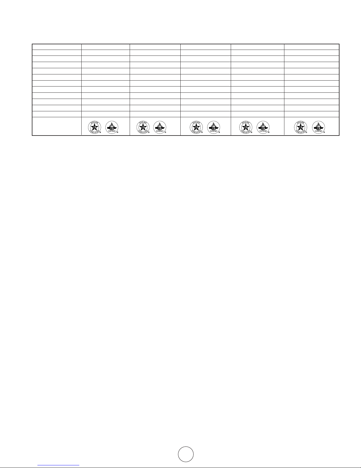
SPECIFICATIONS
CAUTION: CSA certified for use with only No. 1-K kerosene fuel.
Model HS50K HS75KT HS125KT HS175KT HS210KT
Burn Rate: 50,000 Btu/hr (14.7 kW) 75,000 Btu/hr (22 kW) 125,000 Btu/hr (37 kW) 175,000 Btu/hr (51 kW) 210,000 Btu/hr (61.5 kW)
Fuel Rate: 0.37 gal/hr (1.4 L/hr) 0.55 gal/hr (2.1 L/hr) 0.96 gal./hr (3.5 L/hr) 1.3 gal/hr (5.0 L/hr) 1.6 gal/hr (6.0 L/hr)
Electrical Input: 115V, 60Hz, 3.5a 115V, 60Hz, 4a 115V, 60Hz, 5.5a 115V, 60Hz, 5.5a 115V, 60Hz, 5.5a
Line Protection: 10 amps 10 amps 20 amps 20 amps 20 amps
Min. Operating Voltage: 110V 110V 110V 110V 110V
Pressure Setting: 3.8 psig (26.2 kPa) 4.2 psig (29 kPa) 5.1 psig (35.2 kPa) 6.8 psig (46.9 kPa) 8.2 psig (56.5 kPa)
Max. Outlet Temperature: 1300oF (704oC) 1300oF (704oC) 1300oF (704oC) 1300oF (704oC) 1300oF (704oC)
Fuel Tank Capacity: 4 gallons (15.1 L) 6 gallons (22.7 L) 14 gallons (53 L) 14 gallons (53 L) 14 gallons (53 L)
Ignition: Direct Spark, Continuous Direct Spark, Continuous Direct Spark, Continuous Direct Spark, Continuous Direct Spark, Continuous
Spark Generator: Igniter 13 kV, 10ma Igniter 13 kV, 10ma Igniter 13 kV, 10ma Igniter 13 kV, 10ma Igniter 13 kV, 10ma
Primary Safety Control: Solid State Control Solid State Control Solid State Control Solid State Control Solid State Control
Certication:
OPERATING PRECAUTIONS
This is a kerosene, direct-fired, forced air heater. It’s intended use
is primarily temporary heating of buildings under construction,
alteration or repair.
Direct-Fired means that all of the combustion products enter the
heated space. Even though this heater operates very close to 100
percent combustion efficiency, it still produces small amounts of
carbon monoxide. Carbon monoxide (called CO) is toxic. CO can
build up in a heated space and failure to provide adequate ventilation could result in death. The symptoms of inadequate ventilation
are:
• headache
• dizziness
• burning eyes and nose
• nausea
• dry mouth or sore throat
Be sure to follow advice about ventilation in the Safety Precautions
section.
Forced Air means that a blower or fan pushes the air through the
heater. Proper combustion depends upon this air flow; therefore,
the heater must not be revised, modified or operated with parts
removed or missing. Likewise, safety systems must not be circumvented or modified in order to operate the heater.
When the heater is to be operated in the presence of other people
the user is responsible for properly acquainting those present
with the safety precautions and instructions, and of the hazards
involved.
SAFETY PRECAUTIONS
1. Recommended for use with No.1-K kerosene fuel. Factory
tested for use with No.2-K kerosene, No.1 or No.2 Diesel,
No.1 or No.2 fuel oil or JP8 Jet A fuel and these fuels may
be used as well. Never use gasoline, oil drained from crank
cases, naphtha, paint thinners, alcohol or any other highly
flammable fuels.
2. Check the heater thoroughly for damage. DO NOT operate a
damaged heater.
3. DO NOT modify the heater or operate a heater which has
been modified from its original condition.
4. For indoor use only. Not for use where exposed to weather.
5. Use in well ventilated areas, provide at least 2 sq. ft. (0.19
sq. m.) of opening near the floor and 2 sq. ft. (0.19 sq. m.)
near the ceiling directly to outdoors. Increase air openings as
marked for each additional heater.
6. Always keep combustibles, like paper and wood at least
8 ft. (2.4 m) from the heater outlet and 3 ft. (1.0 m) from
the top, sides and inlet. Locate 10 ft. (3.0 m) from canvas
or plastic coverings and secure them to prevent flapping
movement.
7. Caution: Due to the high surface and exhaust temperatures,
adults and children must observe clearances to avoid burns
or clothing ignition. Do Not Touch. Keep children, clothing,
and combustible away.
8. Install the heater such that it is not directly exposed to water
spray, rain and / or water.
9. Never use in areas normally for habitation and /or where
children may be present.
10. Operate only on a stable, level surface. (HS50K & HS75KT –
See wood floor warning).
11. Do not use with duct work. Do not restrict inlet or exit.
12. Use only with electrical power specified. The electrical
connection and grounding must comply with National
Electrical Code – ANSI/NFPA 70 (USA) and CSA C22.1
Canadian Electrical Code, Part 1 (Canada).
13. Use only a properly grounded 3-prong receptacle or
extension cord.
14. Do not move, handle, or service while hot or in operation.
15. Use only in accordance with local, state (provincial) or
national requirements, ordinances and codes.
OPERATING INSTRUCTIONS
UNPACKING
1. Remove heater from carton.
2. Remove all protective material which may have been applied
to the heater for shipment.
3. Check the heater for possible shipping damage. If any
damage is found immediately contact the manufacturer at
800-251-0001.
ASSEMBLY (For 125,000, 175,000 and 210,000 BTU/hr models
only, see figure 1, page 8.)
Wheels and handles are found in the shipping carton along with
mounting hardware. The wheels, axle and mounting hardware are
in a package. Tools required are a 5/16” nut driver, 3/8” open or
adjustable wrench and standard pliers.
1. Assemble the wheels onto the wheel support frame as
follows:
Kerosene Forced Air Heater Operating Instructions and Owner’s Manual
3
Page 4

a. Install one of the cotter pins into the hole on one end of
axle.
b. Slide the large washer, then wheel onto the axle next to the
cotter pin.
c. Slide the spacer onto the axle next to the wheel.
d. Slide the partially assembled axle through the wheel
support frame.
e. Slide the spacer onto the axle next to the wheel support.
f. Slide the wheel then large washer onto the axle and hold in
place with the remaining cotter pin.
g. Install the caps over the larger washers to finish the wheel
assembly.
2. Position the heater on the wheel support frame assembly
with the exit opposite the wheels.
3. Use eight screws and nuts to attach the handles to the top
of the tank flange. The screws will go through the handles,
tank flange and wheel support frame. Install the nuts and
finger tight only until all nuts are installed.
4. Tighten all the nuts.
5. Attach cord caddies to handles using No. (4) & No. (5)
screws and nuts.
PREPARING FOR OPERATION
1. Check the heater for possible shipping damage. If any is
found, immediately contact the manufacturer at
800-251-0001.
2. Follow all of the “Precautions”.
3. Fill the fuel tank with clean kerosene. In extremely cold
weather, condensation may develop in the tank and it is
recommended that a tablespoon of de-icer be added for
each gallon (4 liters) of fuel in the tank. When filling the
heater, use at least 2 gallons (8 liters) of fuel. Be sure heater
is level and do not overfill. Use a funnel or can with a long
fill spout.
IMPORTANT: Before filling fuel tank the first time or after extended storage periods, drain the fuel tank of any moisture
or condensation.
4. Locate heater at a safe distance from combustible materials.
Models 50 & 75 are not suitable for use on wood floors or
other combustible materials. When used, the heater should
rest on suitable insulating material at least 1 inch thick and
extending 3 ft. or more beyond the heater in all directions.
the switch to “On”.
HEATER SHUT DOWN
1. HS50K: Unplug heater from power source.
HS75KT, HS125KT, HS175KT & HS210KT: Push “On/Off”
switch to “Off” position. For extended shutdown, unplug heater from power source.
RESTART AFTER SAFETY SHUTDOWN
(HS50K, HS75KT, HS125KT, HS175KT & HS210KT)
See page 6.
HS50K - Unplug unit. Wait 5 minutes. Plug back in.
HS75KT, HS125KT, HS175KT & HS210KT - Toggle switch to “OFF”
position, wait 5 minutes. Restart.
MAINTENANCE AND STORAGE
WARNING. To prevent personal injury, unplug the heater from the
wall outlet before servicing.
For maximum efficiency and trouble-free service, make the
following periodic maintenance, cleaning and inspections.
ADJUSTING PUMP PRESSURE
Due to varying fuel viscosities and normal component wear the
pump pressure on this heater may need to be adjusted.
ADJUSTMENT PROCEDURE:
1. Fill fuel tank.
2. Start heater.
3. Locate the fuel pressure adjustment screw (ref. #26) in the
exploded parts drawing. The pressure adjustment screw
is located at the rear of the heater, in the air filter housing
cover (slotted adjustment screw approx.10 o’clock position).
4. The plug directly under the adjustment screw can be used to
install a pressure gauge. It is not a second adjustment screw.
5. Using a flat bladed screw driver, turn the pump pressure
adjustment screw clockwise to increase pump pressure and/
or counter-clockwise to decrease pump pressure. Base pump
pressures can be found in the specifications chart on page 3
of the “Operating Instructions and Owners’ Manual”.
6. For best results, the nose cone in the combustion chamber
should be cherry red with no dark spots and the flame
should not extend beyond the nose cone.
HEATER START UP
1. HS50K: Plug the heater into a grounded 115V, 60 Hz, 1 Ø
outlet.
HS75KT, HS125KT, HS175KT & HS210KT: Turn thermostat
to lowest setting, make sure “On/Off” switch is “Off”. Plug
the heater into a grounded 115V, 60 Hz, 1 Ø outlet. Turn
thermostat to highest setting. Start heater by pushing toggle
switch to “On” position (light signifies switch is in “ON”
position). Adjust thermostat to desired setting. Heater will
cycle on/off as heat is required.
EXTENSION CORD REQUIREMENTS: Up to 100’ (30.5m) use
16 awg. conductor. 101’ - 200’ (30.5 - 61.0m) use 14 awg.
conductor.
For all models:
• In cold weather (below 10° F), starting may be improved by
holding a finger over the vent hole of the pump adjustment
screw until the heater starts.
• This unit is equipped with an interrupt circuit. The reset is
integrated into the “On/Off” switch. If the unit does not
start, toggle the switch to “Off”, wait 5 min. and toggle
Kerosene Forced Air Heater Operating Instructions and Owner’s Manual
IMPROPER PRESSURE ADJUSTMENT
Problem: Heater does not have a strong consistent flame.
Heater smokes and spits raw fuel.
Nose cone does not get cherry red.
Adjustment: Pump pressure is too low.
Turn adjustment screw clockwise to increase pump
pressure.
Problem: Flame extends beyond the end of the heater.
Adjustment: Pump pressure is too high.
Turn adjustment screw counter clockwise to
decrease pump pressure.
DAILY SCHEDULE
1. GENERAL. Make general visual inspection of heater for loose
or damaged parts. Check nuts and bolts to insure against
4
Page 5

looseness caused by vibration or rough handling. Damaged
parts should be repaired or replaced before using heater
again. Check heater operation to be sure it is operating
normally (See “Servicing” section for description of normal
operation).
2. FILTERS. Dirty air or fuel filters will cause an imbalance in
the air-fuel mixture. The best indication that this condition
exists is an increase in odors or difficulty getting your heater
to ignite. This heater should never be operated without the
filters in place. If required, clean filters as described under
“500 Hours” and “Annual Schedules”.
500 HOUR SCHEDULE
1. AIR INTAKE FILTER. Remove and wash the filter element
with a mild detergent, dry thoroughly and replace. Do not
oil the filter element. If your heater is used where there
is considerable dust or dirt, clean as often as necessary
(approximately every 50 hrs.).
2. REMOVE DUST. Clean heater twice a season (more often
under dusty conditions). Remove accumulated dust from the
transformer, burner, motor and fan blades with compressed
air. Wipe area clean with a clean dry cloth. Inspect area to
insure all foreign materials are removed, especially around
the burner and combustion area.
3. CAD CELL. Clean the glass portion of the cad cell with a soft
dry cloth.
4. NOZZLE. Accumulation of dirt from fuel and carbon from the
compressor vanes will eventually fill up the passages in the
nozzle, resulting in reduction of fuel and air flow. Pressure
will gradually increase giving improper fuel-air mixture and
excess odor and smoke. If this occurs, replace the fuel
nozzle.
5. FUEL TANK. Clean twice a season (during frequently used
periods, clean twice a month). Drain and flush the fuel tank
with clean fuel oil.
When the heater is working normally:
* The flame is contained within the heater.
* The flame is essentially yellow.
* There is no strong disagreeable odor, eye burning or other
physical discomfort.
* There is no smoke or soot internal or external to the heater.
* There are no unplanned or unexplained shut downs of the
heater.
ANNUAL SCHEDULE
1. AIR OUTPUT FILTER. Remove the air output filter and tap
the contaminated side gently on a solid object to remove
contaminates. Compressed air or liquids should not be used
to clean this filter. Reinstall cleaned filter in filter body in the
same position as it was when removed. If the filter appears
extremely dirty, replace it with a new filter of the same type.
When replacing the filter cover, be sure the gasket is firmly
in place and the screws in the filter cover are tight to prevent
air leaks.
2. FUEL FILTER. Remove the fuel filter from fuel line and direct
compressed air through the filter in the opposite direction
of fuel flow. Safety glasses should be worn when using
compressed air.
3. AIR AND FUEL LINES. If the air or fuel lines are removed
during cleaning, be sure all connections are tight before
operating unit.
STORAGE
Store the heater in a dry location free from fumes or dust.
At the end of each heating season, clean the heater as described
in the MAINTENANCE section. Drain and flush the fuel tank with
clean fuel. The manufacturer recommends completely filling the
tank with fuel for extended storage to minimize condensation
inside the tank.
SERVICING
A hazardous condition may result if a heater is used that has been
modified or is not functioning properly.
Kerosene Forced Air Heater Operating Instructions and Owner’s Manual
5
Page 6

DIAGNOSTIC SAFETY SHUTDOWN AND TROUBLE SHOOTING
These instructions are applicable for HS50K, HS75KT, HS125KT, HS175KT, HS210KT
SYMPTOM TROUBLE
SHOOTING
High limit switch Open Circuit 1) Make sure heater is cooled off, toggle switch to “OFF” position, wait 5
minutes and retry.
Sparks, calling for flame, but 1) Check wiring to motor (per wiring schematic in manual).
no or slow motor operation 2) Make sure that the gauge plug is in place and not damaged.
3) Adjust pressure for proper heater operation per manual.
4) With heater disconnected from AC source, rotate fan clockwise
to verify motor is free.
5) Remove air filter housing from motor and inspect the pump rotor
for damage. If damaged, replace rotor assembly.
6) If wiring is correct, pump rotor is okay, and motor is not rotating
freely, replace motor or power-pack assembly.
7) If problem persists, replace oil flame control assembly.
8) Check for spark arching from the electrode assembly, to the
combustion cylinder.
9) Check the cad cell for continuity.
No Spark 1) Check length and gage of extension cord for proper amp. draw.
(Check requirements on page 4.)
2) Check wiring to igniter (per wiring schematic in manual).
3) Check gap between electrode probes (2.3 - 3 mm).
4) Still no spark, replace igniter assembly.
5) Replace oil flame control assembly.
Abnormal Motor Operation - 1) Motor speed too low (Motor should operate at 3450rpm) -
Motor overheats or Stops Replace motor.
2) With heater disconnected from AC source, rotate fan clockwise
to verify motor is free.
3) Remove air filter housing from motor and inspect the pump rotor
for damage. If damaged, replace rotor assembly.
4) If wiring is correct, pump rotor is okay, and motor is not rotating
freely, replace motor or power-pack assembly.
5) Replace oil flame control assembly.
Unable to Detect Flame 1) Check wiring to cad cell (per wiring schematic in manual).
2) Clean cad cell photo cell.
a) Slide cad cell out of cad cell holder.
b) Push the photo cell out of the black rubber cad cell housing
by pushing on the 2 purple wires.
c) Clean the photo cell with a soft cloth and rubbing alcohol.
d) Pull the photo cell back into the cad cell housing and
reinstall into holder.
e) Test heater.
3) If the heater still does not operate, replace cad cell.
4) Replace oil flame control assembly.
Flame Control Failure 1) Check wiring in heater (per wiring schematic in manual).
2) Replace oil flame control assembly.
Kerosene Forced Air Heater Operating Instructions and Owner’s Manual
6
Page 7
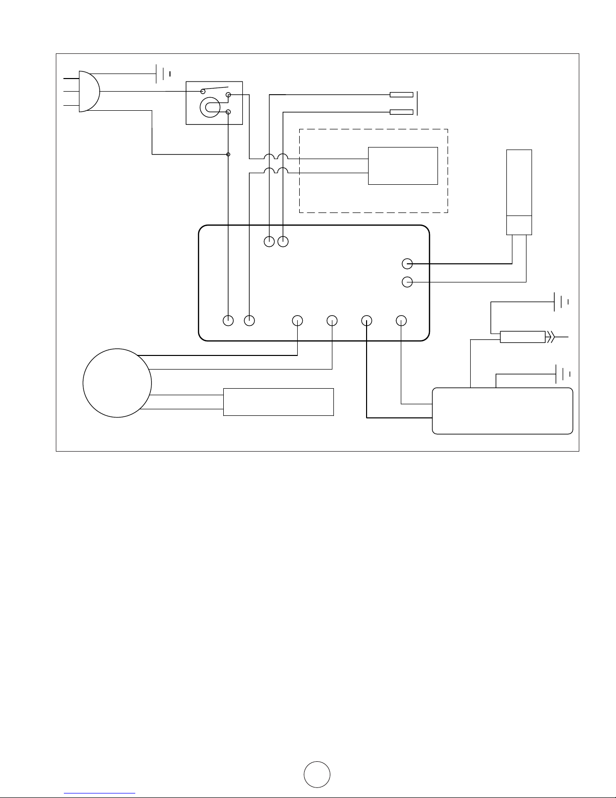
WIRING DIAGRAM
18AWG GRN
18AWG BLK
18AWG WHT
CORD SET
MOTOR
18AWG PINK
18AWG PINK
ON/OFF SWITCH
1
18AWG ORG
18AWG ORG
2
18AWG YELL
3
18AWG YELL
18AWG BLUE
75KT,125KT,175KT,210KT ONLY
H2
H1
FLAME CONTROL SCHEMATIC
(connections may not be in same
position on circuit board)
M1
L
N
M2
MOTOR CAPACITOR
HI-LIMIT
SWITCH
THERMOSTAT
CAD CELL
18AWG PURPLE
COM1
18AWG PURPLE
17AWG BLK
I1
I2
ELECTR0DE
18AWG GRN
17AWG BLK
18AWG RED
IGNITION TRANSFORMER
18AWG RED
The parts lists and wiring diagram show the heater as it was
constructed. Do not use a heater which is different from that
shown. Heater performance is effected by air pressure setting. If there is any uncertainty about the air pressure setting,
have it checked.
A heater which is not working right must be repaired, but only
by a trained, experienced service person.
Kerosene Forced Air Heater Operating Instructions and Owner’s Manual
7
Page 8
®
OPERATING INSTRUCTIONS
AND OWNER’S MANUAL
WARNING:
USE ONLY MANUFACTURER’S REPLACEMENT PARTS. USE OF ANY OTHER PARTS
COULD CAUSE INJURY OR DEATH. REPLACEMENT PARTS ARE ONLY AVAILABLE
DIRECT FROM THE FACTORY AND MUST BE INSTALLED BY A QUALIFIED SERVICE
AGENCY.
PARTS ORDERING INFORMATION:
PURCHASING: Accessories may be purchased at any HEATSTAR by ENERCO local
dealer or direct from the factory
FOR INFORMATION REGARDING SERVICE
Please call Toll-Free 866-447-2194
www.heatstarbyenerco.com
Our office hours are 8:00 AM – 5:00 PM, EST, Monday through Friday.
Model #
HS50K, HS75KT,
HS125KT, HS175KT,
HS210KT
Please include the model number, date of purchase, and description of problem in
all communication.
LIMITED WARRANTY
Enerco Technical Products, Inc. warrants its heaters and accessories to be free from
defects in material and workmanship for a period of 1 year from date of purchase.
Enerco Technical Products, Inc. will repair or replace this product free of charge
if it has been proven to be defective within the 1-year period, and is returned at
customer expense with proof of purchase to Enerco Technical Products, Inc. within
the warranty period.
Mr. Heater, Inc. reserves the right to make changes at any time, without notice or
obligation, in colors, specifications, accessories, materials and models.
PRODUCT REGISTRATION: Thank you for your purchase.
Please log in to http://www.egiregistration.com to register your product.
HEATSTAR by ENERCO, 4560 W. 160TH ST., CLEVELAND, OHIO 44135
866-447-2194
© 2015, Enerco Technical Products, Inc. All rights reserved
UL733, CSA B140.8, CSA B140.9.3
Page 9

GUIDE D'UTILISATION
®
ET INSTRUCTIONS DE
FONCTIONNEMENT
LISEZ SOIGNEUSEMENT LES INSTRUCTIONS. Lisez et observez toutes les instructions. Conservez
les instructions pour vous y référer ultérieurement. Interdisez à quiconque n'ayant pas lu les présentes
instructions d'assembler, d'allumer, de régler ou de faire fonctionner cet appareil de chauffage.
Modèle #
HS50K, HS75KT,
HS125KT, HS175KT,
HS210KT
APPAREIL DE CHAUFFAGE
À AIR PULSÉ AU KÉROSÈNE
AVERTISSEMENT : Le non-respect des instructions, telles qu'indiquées dans le
présent guide, risque d'entraîner une explosion ou un incendie entraînant des
dommages matériels ou des blessures graves, voire mortelles.
– N'entreposez pas et n'utilisez pas d'essence ou d'autres liquides ou vapeurs inflammables
à proximité de ce type d'appareil.
– L'entretien doit être effectué par un fournisseur de services d'entretien qualifié.
Cet appareil de chauffage portatif n'est pas ventilé. Il utilise l'oxygène de l'air ambiant. Une
circulation d'air adéquate doit être assurée pour la combustion et la ventilation. Voir page 3.
UL733, CSA B140.8, CSA B140.9.3
HEATSTAR by ENERCO, 4560 W. 160TH ST., CLEVELAND, OHIO 44135 USA • 866-447-2194
01/15 70204 2015 JM
Page 10

AVERTISSEMENT :
VOTRE SÉCURITÉ PERSONNELLE ÉTANT IMPORTANTE POUR
TOUS, VEUILLEZ LIRE LES INSTRUCTIONS AVANT D'UTILISER
CET APPAREIL DE CHAUFFAGE.
AVERTISSEMENT GÉNÉRAL DE DANGER :
LE NON-RESPECT DES MESURES DE PRÉVENTION ET INSTRUCTIONS
FOURNIES AVEC CET APPAREIL DE CHAUFFAGE RISQUE DE CAUSER
LA MORT, DES BLESSURES GRAVES ET DES DOMMAGES OU DES
PERTES MATÉRIELLES RÉSULTANT D'INCENDIE, D'EXPLOSION,
DE BRÛLURE, D'ASPHYXIE, D'INTOXICATION AU MONOXYDE DE
CARBONE OU D'ÉLECTROCUTION.
SEULES LES PERSONNES APTES À COMPRENDRE ET À RESPECTER
LES INSTRUCTIONS DEVRAIENT UTILISER OU EFFECTUER
L'ENTRETIEN DE CET APPAREIL DE CHAUFFAGE.
SI VOUS AVEZ BESOIN D'AIDE OU D'INFORMATION AU SUJET
DE L'APPAREIL DE CHAUFFAGE (MANUEL D'INSTRUCTIONS,
ÉTIQUETTES, ETC.), VEUILLEZ COMMUNIQUER AVEC LE FABRICANT.
AVERTISSEMENT :
LE MONOXYDE DE CARBONE PEUT VOUS TUER.
L'UTILISATION D'UN APPAREIL DE CHAUFFAGE DE CAMPING
PORTATIF À GAZ DANS UNE TENTE, UN VÉHICULE RÉCRÉATIF,
UNE ROULOTTE, UNE VOITURE, UN ABRI OU TOUT AUTRE
ENDROIT FERMÉ PRODUIT DU MONOXYDE DE CARBONE,
UN GAZ MORTEL.
AVERTISSEMENT :
NON CONÇU POUR ÊTRE UTILISÉ DANS UNE HABITATION
OU UN VÉHICULE RÉCRÉATIF.
AVERTISSEMENT :
DANGER D'INCENDIE, D'EXPLOSION ET D'INHALATION.
CONSERVEZ LES MATÉRIAUX COMBUSTIBLES TELS QUE LES
MATÉRIAUX DE CONSTRUCTION, LE PAPIER ET LE CARTON À
UNE DISTANCE SÉCURITAIRE DE L'APPAREIL DE CHAUFFAGE
COMME LE RECOMMANDENT LES INSTRUCTIONS. N'UTILISEZ
JAMAIS L'APPAREIL DE CHAUFFAGE DANS UN LOCAL QUI
CONTIENT OU RISQUE DE CONTENIR DES PARTICULES
COMBUSTIBLES EN SUSPENSION DANS L'AIR OU DES
PRODUITS TELS QUE DE L'ESSENCE, DES SOLVANTS, DU
DILUANT À PEINTURE, DES PARTICULES DE POUSSIÈRE OU
DES PRODUITS CHIMIQUES INCONNUS.
AVERTISSEMENT :
L’État de la Californie exige que l’avertissement suivant soit fourni :
L'UTILISATION DE CET APPAREIL GÉNÈRE DES SOUS-PRODUITS
DE COMBUSTION CONTENANT DU MONOXYDE DE CARBONE,
PRODUIT CHIMIQUE RECONNU PAR L'ÉTAT DE LA CALIFORNIE
COMME CAUSE DE CANCER ET D'ANOMALIES CONGÉNITALES
(OU AUTRES RISQUES POUR LA REPRODUCTION).
CET APPAREIL CONTIENT DES PRODUITS CHIMIQUES
RECONNUS PAR L’ÉTAT DE CALIFORNIE COMME POUVANT
CAUSER LE CANCER ET DES MALFORMATIONS CONGÉNITALES
OU AUTRES DOMMAGES AU SYSTÈME REPRODUCTEUR.
AVERTISSEMENT :
• N'EMPLOYEZ PAS D'ESSENCE, DE NAPHTE OU DE
PRODUITS COMBUSTIBLES VOLATILS.
• ARRÊTEZ L'APPAREIL DE CHAUFFAGE AVANT D'Y
AJOUTER DU COMBUSTIBLE.
• REMPLISSEZ TOUJOURS LE RÉSERVOIR À L'EXTÉRIEUR,
LOIN D'UNE FLAMME NUE.
• N'UTILISEZ PAS DE SOURCE DE COMBUSTIBLE EXTERNE.
• NE FAITES PAS FONCTIONNER L'APPAREIL DE CHAUFFAGE
SI DES VAPEURS OU DES LIQUIDES INFLAMMABLES
RISQUENT D'ÊTRE PRÉSENTS.
• NE DÉMARREZ PAS L'APPAREIL DE CHAUFFAGE SI LA
CHAMBRE DE COMBUSTION EST CHAUDE.
• NE DÉMARREZ PAS L'APPAREIL DE CHAUFFAGE SI UN
SURPLUS DE COMBUSTIBLE S'EST ACCUMULÉ DANS LA
CHAMBRE DE COMBUSTION.
• NE PLACEZ PAS D'USTENSILES DE CUISSON SUR
L'APPAREIL DE CHAUFFAGE.
• BRANCHEZ LE CORDON ÉLECTRIQUE DANS UNE PRISE
À TROIS BROCHES ADÉQUATEMENT MISE À LA TERRE.
AVERTISSEMENT RELATIF AUX
MODÈLES HS50K ET HS75KT :
Non conçu pour être utilisé sur des planchers de bois
ou d'autres matériaux combustibles. Lors de son
fonctionnement, l'appareil de chauffage doit reposer sur
un matériau isolant adéquat d'au moins 2,5 cm (1 po)
d'épaisseur et dépassant l'appareil d'au moins 90 cm (3 pi)
de tous les côtés.
TABLE DES MATIÈRES
AVERTISSEMENTS ....................................................................... 2
FICHE TECHNIQUE ...................................................................... 3
PRÉCAUTIONS LIÉES AU FONCTIONNEMENT .............................. 3
PRÉCAUTIONS LIÉES À LA SÉCURITÉ ........................................... 3
INSTRUCTIONS D'UTILISATION .................................................... 3
ENTRETIEN, ENTREPOSAGE ET RÉPARATION ................................ 4
DÉPANNAGE ............................................................................... 6
SCHÉMA DE CÂBLAGE ................................................................ 7
LISTE DES PIÈCES ........................................................................ 8
VUE ÉCLATÉE .............................................................................. 9
GARANTIE .................................................................................10
INSTRUCTIONS POUR LA COMMANDE DE PIÈCES .....................10
Kerosene Forced Air Heater Operating Instructions and Owner’s Manual
2
Page 11

SPÉCIFICATIONS
PRUDENCE : CSA certifié pour l’utilisation avec seulement No. 1-K le combustible de pétrole.
Modèles HS50K HS75KT HS125KT HS175KT HS210KT
Taux de combustion : 50 000 Btu/h (14.7 kW) 75 000 Btu/h (22 kW) 125 000 Btu/h (37 kW) 175 000 Btu/h (51 kW) 210 000 Btu/h (61,5 kW)
Consommation de 0,37 gal/h (1,4 L/h) 0,55 gal/h (2,1 L/h) 0,96 gal/h (3,5 L/h) 1,3 gal/h (5,0 L/h) 1,6 gal/h (6,0 L/h)
combustible :
Consommation électrique : 115 V, 60 Hz, 3,5 A 115 V, 60 Hz, 4 A 115 V, 60 Hz, 5,5 A 115 V, 60 Hz, 5,5 A 115 V, 60 Hz, 5,5 A
Courant maximal : 10 A 10 A 20 A 20 A 20 A
Tension minimale : 110 V 110 V 110 V 110 V 110 V
Pression : 3,8 psig (26.2 kPa) 4,2 psig (29 kPa) 5,,1 psig (35,2 kPa) 6,8 psig (46,9 kPa) 8,2 psig (56,5 kPa)
Température de sortie 704 oC (1 300 oF) 704
maximale :
Contenance du réservoir : 4 gallons (15,1 L) 6 gallons (22,7 L) 14 gallons (53 L) 14 gallons (53 L) 14 gallons (53 L)
Allumage : Par étincelle, en continu Par étincelle, en continu Par étincelle, en continu Par étincelle, en continu Par étincelle, en continu
Générateur d'étincelle : Allumeur 13 kV, 10 mA Allumeur 13 kV, 10 mA Allumeur 13 kV, 10 mA Allumeur 13 kV, 10 mA Allumeur 13 kV, 10 mA
Appareil de commande : Commande transistorisée Commande transistorisée Commande transistorisée Commande transistorisée Commande transistorisée
Certication:
o
C (1 300 oF) 704
o
C (1 300 oF) 704
o
C (1 300 oF) 704
o
C (1 300 oF)
PRÉCAUTIONS LIÉES AU
FONCTIONNEMENT
Cet appareil de chauffage à air pulsé et à feu direct fonctionne au
kérosène. Il est destiné principalement à chauffer temporairement
des édifices en construction, en rénovation ou en réparation.
Le fonctionnement à feu direct de cet appareil signifie que tous les
produits de combustion se retrouvent dans l'air ambiant. Même si
la combustion de l'appareil de chauffage est presque complète,
il produit quand même de petites quantités de monoxyde de
carbone. Le monoxyde de carbone (appelé CO) est toxique. Il
est possible que le CO s'accumule dans le local à chauffer. Une
ventilation inadéquate pourrait ainsi causer la mort. Les symptômes
ressentis en cas de ventilation inadéquate sont les suivants :
• mal de tête
• étourdissement
• sensation de brûlure au nez et aux yeux
• nausée
• mal de gorge ou bouche sèche
Assurez-vous de respecter les conseils au sujet de la ventilation
mentionnés dans la section Précautions liées à la sécurité.
Un appareil à air pulsé signifie que l'air est soufflé dans l'appareil
de chauffage par une soufflerie. La qualité de la combustion
dépend du débit d'air. Par conséquent, l'appareil de chauffage ne
doit pas être modifié ni être utilisé si des pièces sont manquantes.
De même, les systèmes de sécurité ne doivent pas être contournés
ni modifiés pour faire fonctionner l'appareil.
Lorsque l'appareil de chauffage doit fonctionner en présence
d'autres personnes, l'utilisateur est responsable d'informer ces
dernières des instructions et précautions liées à la sécurité et de
les avertir des dangers inhérents.
PRÉCAUTIONS LIÉES À LA SÉCURITÉ
1. Recommandé pour l’utilisation avec le combustible de pétrole
No.1-K. Testé en usine pour l’utilisation avec le pétrole
No.2-K, No.1 ou le gazole No.2, No.1 ou le fuel No.2 ou
le Jet de JP8 un combustible et ces combustibles peuvent
être utilisés aussi. N’utilisez jamais de l’essence, le pétrole
égoutté des cas de fanatique, le naphte, du diluant pour
peintures, de l’alcool ou autres combustibles extrêmement
inflammables.
2. Vérifiez attentivement si l'appareil de chauffage a subi
des dommages. NE FAITES PAS fonctionner un appareil
endommagé.
3. NE MODIFIEZ PAS l'appareil de chauffage et ne le faites pas
fonctionner s'il n'est plus dans son état d'origine.
4. Pour utilisation intérieure seulement. L'appareil ne doit pas
être exposé aux intempéries.
5. Faites fonctionner l'appareil dans des endroits bien aérés
en laissant une ouverture d'au moins 0,19 m² (2 pi²) près
du plancher et une autre d'au moins 0,19 m² (2 pi²) près du
plafond, qui donnent directement sur l'extérieur. Augmentez
la dimension de ces ouvertures tel qu'indiqué pour chaque
appareil de chauffage additionnel.
6. Gardez tous les matériaux combustibles, comme le papier
et le bois, à au moins 2,4 m (8 pi) de la sortie de l'appareil
de chauffage et à 1,0 m (3 pi) du dessus et des côtés de
l'appareil ainsi que de la prise d'air. Placez l'appareil à 3 m
(10 pi) des toiles et des revêtements plastiques, et fixez-les
afin d'empêcher tout battement.
7. Attention : En raison des températures élevées à la
surface et à la sortie, les adultes et les enfants doivent
respecter les distances de sécurité pour éviter les brûlures
et l'inflammation des vêtements. Ne touchez pas à
l'appareil. Gardez les enfants, les vêtements et les produits
combustibles à bonne distance de l'appareil.
8. Placez l'appareil de chauffage de façon à ce qu'il ne soit pas
exposé directement à l'eau.
9. Ne l'utilisez jamais dans des endroits qui servent
normalement à l'habitation ni où sont présents des enfants.
10. Utilisez uniquement sur des surfaces stables et de niveau.
(HS50K et HS75KT – Voir l'avertissement au sujet des
planchers de bois.)
11. N'utilisez pas l'appareil avec des conduits d'air. N'obstruez pas
l'entrée et la sortie d'air.
12. Utilisez uniquement avec l'alimentation électrique spécifiée.
Le raccordement électrique et la mise à la terre doivent être
conformes au Code national de l'électricité – ANSI/NFPA 70
(É.-U.) – et au Code canadien de l'électricité – CSA C22.1 –
partie 1 (Canada).
13. N'utilisez qu'avec une fiche ou une rallonge mise à la terre
munie de trois broches.
14. Ne déplacez pas l'appareil, ne lui touchez pas et n'essayez
pas d'en faire l'entretien lorsqu'il est chaud.
15. Utilisez-le uniquement en conformité avec les codes, les
ordonnances et les exigences de la province, de l'État ou de
la municipalité concernés.
Kerosene Forced Air Heater Operating Instructions and Owner’s Manual
3
Page 12

INSTRUCTIONS DE
FONCTIONNEMENT
DÉBALLAGE
1. Retirez l'appareil de chauffage de la boîte.
2. Enlevez tout le matériel de protection installé sur l'appareil
pour le transport.
3. Vérifiez soigneusement tout dommage qu'aurait pu subir
l'appareil de chauffage pendant l'expédition. Si vous
constatez quelque dommage, avisez immédiatement le
fabricant au 1 800 251-0001.
ASSEMBLAGE (Pour modèles de 125 000, 175 000 et
210 000 BTU/h uniquement, voir la figure 1, page 8.)
Les roues et les poignées se trouvent dans la boîte avec les pièces
servant à l'assemblage. Les roues, l'essieu et les pièces servant à
l'assemblage se trouvent dans un emballage. Les outils nécessaires
sont une clé de 5/16 po, une clé ou une clé à molette de 3/8 po
et une pince ordinaire.
1.
Assemblez les roues sur leur cadre de support de la façon suivante :
a. Insérez l'une des goupilles fendues dans le trou situé au bout de
l'essieu.
b. Insérez la grande rondelle sur l'essieu, à côté de la goupille
fendue, puis la roue.
c. Insérez un séparateur sur l'essieu jusqu'à côté de la roue.
d. Insérez l'essieu partiellement assemblé dans le cadre de support
des roues.
e. Insérez un séparateur sur l'essieu jusqu'à côté du support de roue.
f. Insérez la roue sur l'essieu, puis la grande rondelle et fixez-les en
place avec l'autre goupille fendue.
g. Installez les capuchons sur les grandes rondelles pour terminer
l'assemblage des roues.
2. Placez l'appareil de chauffage sur le cadre de support des roues, le
côté sortie opposé aux roues.
3. À l'aide des huit écrous et boulons, fixez les poignées au dessus de
la bride du réservoir. Les boulons traverseront les poignées, la bride
du réservoir et le cadre de support des roues. Vissez les écrous à la
main et ne les serrez pas avant qu'ils ne soient tous vissés.
4. Serrez tous les écrous.
5. Fixez les guides de cordon aux poignées à l'aide de boulons et
écrous # 4 et # 5.
AVANT LE FONCTIONNEMENT
1. Vérifiez soigneusement tout dommage qu'aurait pu subir
l'appareil de chauffage pendant l'expédition. Si vous
constatez des dommages, avisez immédiatement le fabricant
au 1 800 251-0001.
2. Respectez toutes les « Précautions ».
3. Remplissez le réservoir de kérosène propre. Dans des conditions
de froid intense, il est possible que de la condensation se forme
dans le réservoir. Il est donc recommandé d'ajouter une cuillère à
table de liquide antigivrant par 4 litres (1 gallon) de combustible.
Utilisez au moins 8 litres (2 gallons) de combustible lors du
remplissage du réservoir. Assurez-vous que l'appareil de chauffage
est de niveau et que le réservoir ne déborde pas. Servez-vous d'un
entonnoir ou d'un contenant muni d'un long bec verseur.
IMPORTANT : Avant de remplir le réservoir la première fois
ou après des périodes d'entreposage prolongées, enlevez-en
la condensation.
4. Placez l'appareil de chauffage à une distance sécuritaire
des matériaux combustibles. Les modèles 50 et 75 ne
sont pas conçus pour être utilisés sur des planchers de
bois ou d'autres matériaux combustibles. Lors de son
fonctionnement, l'appareil de chauffage doit reposer sur
un matériau isolant adéquat d'au moins 2,5 cm (1 po)
d'épaisseur et dépassant l'appareil d'au moins 90 cm (3 pi)
ou plus de tous les côtés.
DÉMARRAGE DE L'APPAREIL
1. HS50K : Branchez le câble d'alimentation dans une prise
mise à la terre de 115 V, 60 Hz, 1 Ø.
HS75KT, HS125KT, HS175KT et HS210KT : Réglez le
thermostat au minimum et assurez-vous que l'interrupteur
est à « OFF ». Branchez le cordon de l'appareil de chauffage
dans une prise mise à la terre de 115 V, 60 Hz, 1 Ø. Réglez le
thermostat à sa position la plus élevée. Démarrez l'appareil
de chauffage en plaçant l'interrupteur basculant à la position
« ON » (Marche). Réglez le thermostat à la température désirée.
L'appareil de chauffage s'arrêtera et redémarrera au besoin.
CONDITIONS POUR UTILISER UNE RALLONGE ÉLECTRIQUE :
pour une rallonge jusqu'à 30,5 m (100 pi), conducteurs de
calibre 16; pour une rallonge de 30,5 à 61 m (101-200 pi),
conducteurs de calibre 14.
Pour tous les modèles :
• Lorsque la température est inférieure à -12 °C (10 °F), le
démarrage sera facilité si l'on met un doigt sur l'orifice de
ventilation de la vis de réglage de pression jusqu'à ce que
l'appareil de chauffage démarre.
• Cet appareil est équipé d'un disjoncteur intégré à l'interrupteur
marche-arrêt. Si l'appareil ne démarre pas, placez l'interrupteur
à « OFF », attendez 5 minutes et placez-le à « ON ».
ARRÊT DE L'APPAREIL
1. HS50K : Débranchez l'appareil.
HS75KT, HS125KT, HS175KT et HS210KT : Placez
l'interrupteur à
l'appareil de chauffage de sa source d'alimentation.
« OFF »
. Pour un arrêt prolongé, débranchez
REDÉMARRAGE APRÈS UN ARRÊT D'URGENCE
(HS50K, HS75KT, HS125KT, HS175KT et HS210KT)
Voir page 6.
HS50K : Débranchez l'appareil, attendez cinq minutes puis
rebranchez l'appareil.
HS75KT, HS125KT, HS175KT et HS210KT : Placez l'interrupteur
à
« OFF »
, attendez 5 minutes puis démarrez l'appareil.
ENTRETIEN ET ENTREPOSAGE
AVERTISSEMENT. Pour éviter toute blessure, débranchez l'appareil
de chauffage de la prise murale avant d'en effectuer l'entretien.
Pour optimiser le fonctionnement et éviter les problèmes, effectuez
régulièrement les inspections, le nettoyage et l'entretien suivants.
RÉGLAGE DE PRESSION DE LA POMPE
En raison des variations de viscosité des combustibles et de l'usure
normale des pièces, il peut devenir nécessaire de régler la pression
de la pompe.
POUR RÉGLER LA PRESSION :
1. Remplissez le réservoir.
2. Démarrez l'appareil.
3. Repérez la vis du régulateur de pression de combustible (# 26
de la vue éclatée). Le vis d’ajustage de pression est trouvee
a la’arriere du chauffage, dans l’habition de filtre a air 9la vis
d’ajustage emboitee environ 10 position d’heure).
4. La prise de courant directement sous la vis d’ajustage peut
Kerosene Forced Air Heater Operating Instructions and Owner’s Manual
4
Page 13

etre enlevee pour l’installation d’un indiccateur de pressions.
Ce n’est pas une deuxieme vis d’ajustage.
5. À l'aide d'un tournevis plat, serrez la vis pour augmenter
la pression ou desserrez-la pour réduire la pression.
Les pressions nominales sont indiquées dans le tableau
des spécifications à la page 3 du Guide d'utilisation et
instructions de fonctionnement.
6. Pour une efficacité maximale, le cône avant de la chambre
de combustion doit être rouge cerise sans présenter de
taches foncées, et la flamme ne doit pas se prolonger audelà du cône.
SYMPTÔMES DE RÉGLAGE DE PRESSION INCORRECT
Problème : L'appareil ne produit pas une flamme forte et
homogène.
L'appareil émet de la fumée et éjecte du
combustible brut.
Le cône avant ne devient pas rouge cerise.
Cause : La pression est trop faible.
Serrez la vis de réglage pour augmenter la pression
de la pompe.
Problème : La flamme dépasse l'extrémité du tube de sortie.
Cause : La pression est trop forte.
Desserrez la vis pour réduire la pression de la
pompe.
PROGRAMME QUOTIDIEN
1. GÉNÉRAL. Faites une inspection visuelle générale de l'appareil
de chauffage pour déceler les pièces endommagées ou
desserrées. Inspectez les boulons et les écrous pour vous assurer
que les vibrations et les manipulations brusques ne les ont pas
desserrés. Les pièces endommagées doivent être réparées ou
remplacées avant d'utiliser à nouveau l'appareil de chauffage.
Vérifiez si l'appareil fonctionne normalement (consultez la section
« Réparation » pour une description du fonctionnement normal).
2. FILTRES. Les filtres à air et à combustible doivent être propres
pour assurer l'équilibre du mélange air-combustible. À défaut de
quoi, l'odeur augmentera et l'appareil de chauffage démarrera
difficilement. Ne faites pas fonctionner l'appareil sans les filtres.
Si nécessaire, nettoyez les filtres tel qu'il est décrit aux sections
« Programme 500 heures » et « Programme annuel ».
PROGRAMME 500 HEURES
1. FILTRE D'ADMISSION D'AIR. Enlevez le filtre et lavez-le à l'aide
d'un détergent doux. Séchez-le à fond et remettez-le en place.
Ne huilez pas l'élément filtrant. Si vous utilisez l'appareil dans un
endroit contenant beaucoup de poussières et de saletés, nettoyez
le filtre aussi souvent que requis (aux 50 heures environ).
2. ENLÈVEMENT DE LA POUSSIÈRE. Nettoyez l'appareil de chauffage
deux fois par saison (plus souvent dans les endroits poussiéreux).
Enlevez la poussière accumulée sur le transformateur, le brûleur, le
moteur et les pales du ventilateur à l'aide d'un jet d'air comprimé.
Essuyez les surfaces avec un chiffon sec et propre. Inspectez ces
endroits pour vous assurer que toute matière étrangère a été
enlevée, particulièrement autour du brûleur et de la zone de
combustion.
3. CELLULE AU CADMIUM. Nettoyez la partie vitrée de la cellule au
cadmium à l'aide d'un chiffon doux et sec.
4. GICLEUR. L'accumulation de saleté de combustible et de carbone
causée par l'aube d'entrée obstruera éventuellement les conduits
du gicleur et entraînera une diminution du débit d'air et de
combustible. La pression augmentera graduellement, ce qui
déséquilibrera le mélange air-combustible et produira un surplus
de fumée et d'odeur. Dans un tel cas, remplacez le gicleur.
5. RÉSERVOIR DE COMBUSTIBLE. Nettoyez-le deux fois par saison
(au cours des périodes d'utilisation intensive, nettoyez-le deux
fois par mois). Rincez et vidangez le réservoir à l'aide de mazout
propre.
PROGRAMME ANNUEL
1. FILTRE DE SORTIE D'AIR. Enlevez le filtre de sortie d'air et
frappez-en doucement le côté sale sur un objet dur pour enlever
les saletés. N'utilisez pas d'air comprimé ni de liquide pour
nettoyer le filtre. Replacez le filtre propre dans son réceptacle
dans la position où il était. Si le filtre paraît extrêmement
sale, remplacez-le par un autre du même type. En remettant
le couvercle du filtre en place, assurez-vous que le joint
d'étanchéité est solidement en place et que les vis du couvercle
sont assez serrées pour empêcher des fuites d'air.
2. FILTRE À COMBUSTIBLE. Enlevez le filtre de la canalisation de
combustible et dirigez de l'air comprimé à travers le filtre dans
le sens contraire du débit du combustible. Veuillez porter des
lunettes protectrices en utilisant de l'air comprimé.
3. CANALISATIONS D'AIR ET DE COMBUSTIBLE. Si ces
canalisations sont enlevées au cours du nettoyage, assurez-vous
de bien serrer les raccords avant de faire fonctionner l'appareil.
ENTREPOSAGE
Entreposez l'appareil de chauffage dans un endroit sec exempt de
vapeurs et de poussières.
À la fin de chaque saison, nettoyez l'appareil de chauffage tel
qu'indiqué dans la section ENTRETIEN. Rincez et vidangez le
réservoir à l'aide de combustible propre. Le fabricant recommande
de remplir complètement le réservoir de combustible avant un
entreposage prolongé pour diminuer les risques de condensation.
ENTRETIEN
Un appareil de chauffage qui a été modifié ou qui ne fonctionne
pas correctement risque d'être une cause de dangers.
Lorsque l'appareil de chauffage fonctionne normalement :
* La flamme reste dans l'appareil de chauffage.
* La flamme est vraiment jaune.
* Il n'y a pas de forte odeur désagréable, pas de sensation de
brûlure aux yeux, ni de malaise physique général.
* Il n'y a pas de fumée ni de suie à l'intérieur ou à l'extérieur de
l'appareil de chauffage.
* Il ne se produit pas d'arrêts imprévus ou inexpliqués de
l'appareil.
Kerosene Forced Air Heater Operating Instructions and Owner’s Manual
5
Page 14

DIAGNOSTIC ET DÉPANNAGE APRÈS UN ARRÊT D'URGENCE
Ces instructions s'appliquent aux modèles HS50K, HS75KT, HS125KT, HS175KT, HS210KT
S
YMPTÔME DÉPANNAGE
Circuit ouvert du contacteur de commande maximale 1) Assurez-vous que l'appareil est refroidi, placez l'interrupteur à « OFF », attendez
5 minutes et redémarrez l'appareil.
Présence d'étincelles et appel de flamme, mais 1) Vérifiez le câblage vers le moteur (selon le schéma de câblage du présent guide).
le moteur ne fonctionne pas ou tourne à très bas régime 2) Assurez-vous que le bouchon du manomètre est bien en place et qu'il n'est pas
endommagé.
3) Réglez la pression pour assurer le bon fonctionnement de l'appareil de chauffage selon
les spécifications du présent guide.
4) Débranchez l'appareil, puis tournez le ventilateur dans le sens horaire pour vérifier si le
moteur tourne librement.
5) Retirez le boîtier du filtre à air du moteur et vérifiez si le rotor de la pompe présente des
dommages. Au besoin, remplacez le rotor.
6) Si le câblage est adéquat, que le rotor est en bon état et que le moteur ne tourne pas
librement, remplacez le moteur ou le boîtier d'alimentation.
7) Si le problème persiste, remplacez l'ensemble commande de flamme.
8) Vérifiez si un arc électrique se produit entre l'électrode et le cylindre de combustion.
9) Vérifiez la continuité de la cellule au cadmium.
Aucune étincelle 1) Assurez-vous que la longueur et le calibre de la rallonge électrique sont conformes aux
spécifications (voir page 4).
2) Vérifiez le câblage vers l'allumeur (selon le schéma de câblage du présent guide).
3) Vérifiez l'écart entre les pointes d'électrode (2,3 - 3 mm).
4) S'il n'y a toujours pas d'étincelle, remplacez l'allumeur.
5) Remplacez l'ensemble commande de flamme.
Fonctionnement anormal du moteur – 1) Régime moteur trop bas (le moteur doit tourner à 3 450 tr/min) – Remplacez le moteur.
Le moteur surchauffe ou s’arrête 2) Débranchez l'appareil, puis tournez le ventilateur dans le sens horaire pour vérifier si le
moteur tourne librement.
3) Retirez le boîtier de filtre à air du moteur et vérifiez si le rotor de la pompe présente
des dommages. Au besoin, remplacez le rotor.
4) Si le câblage est adéquat, que le rotor est en bon état et que le moteur ne tourne pas
librement, remplacez le moteur ou le boîtier d'alimentation.
5) Remplacez l'ensemble commande de flamme.
La flamme n'est pas détectée 1) Vérifiez le câblage vers la cellule au cadmium (selon le schéma de câblage du présent
guide).
2) Nettoyez l'élément photoélectrique de la cellule au cadmium.
a) Dégagez la cellule au cadmium de son support.
b) Dégagez l'élément photoélectrique du caoutchouc noir du boîtier de la cellule
en poussant sur les 2 fils violets.
c) Nettoyez l'élément photoélectrique avec un chiffon doux et de l'alcool à friction.
d) Remettez l'élément photoélectrique dans le boîtier de la cellule au cadmium,
puis réinstallez le support.
e) Vérifiez le fonctionnement de l'appareil de chauffage.
3) Si l'appareil ne fonctionne toujours pas, remplacez la cellule au cadmium.
4) Remplacez l'ensemble commande de flamme.
Défaillance de la commande de flamme 1) Vérifiez le câblage de l'appareil de chauffage (selon le schéma de câblage du présent
guide).
2) Remplacez l'ensemble commande de flamme.
Kerosene Forced Air Heater Operating Instructions and Owner’s Manual
6
Page 15

SCHÉMA DE CÂBLAGE
VRT AWG 18
NOIR AWG 18
BLC AWG 18
CORDON
D’ALIMENTATION
MOTEUR
INTERRUPTEUR
MARCHE-ARRÊT
1
ORG AWG 18
ORG AWG 18
ROSE AWG 18
ROSE AWG 18
2
3
L
N
JAUNE AWG 18
JAUNE AWG 18
BLEU AWG 18
H2
H1
SCHÉMA DE LA COMMANDE DE
(la position des connexions peut
différer sur le circuit imprimé)
CONDENSATEUR
DU MOTEUR
FLAMME
M1
M2
INTERRUPTEUR
COMMANDE MAX.
THERMOSTAT
COM1
I1
I2
RGE AWG 18
RGE AWG 18
VIOLET AWG 18
VIOLET AWG 18
NOIR AWG 17
TRANSFORMATEUR
D’ALLUMAGE
CELLULE AU
CADMIUM
NOIR AWG 17
ÉLECTRODE
VRT AWG 18
La liste des pièces et le schéma de câblage présentent
l'appareil de chauffage tel qu'il a été construit. N'utilisez pas
un appareil de chauffage qui diffère de ce qui est illustré. Le
rendement de l'appareil de chauffage dépend du réglage de la
pression d'air. Si vous avez un doute au sujet de la pression
d'air,faites-lavérier.
Si l'appareil de chauffage ne fonctionne pas correctement, il
doit être réparé uniquementparuntechnicienqualié.
Kerosene Forced Air Heater Operating Instructions and Owner’s Manual
7
Page 16

***PAGE LEFT INTENTIONALLY BLANK***
Kerosene Forced Air Heater Operating Instructions and Owner’s Manual
10
Page 17

GUIDE D'UTILISATION
ET INSTRUCTIONS DE
FONCTIONNEMENT
Modèle #
HS50K, HS75KT,
HS125KT, HS175KT,
HS210KT
AVERTISSEMENT :
N'UTILISEZ QUE LES PIÈCES DE RECHANGE DU FABRICANT. L'UTILISATION D'AUTRES
PIÈCES RISQUE DE CAUSER DES BLESSURES ET LA MORT. LES PIÈCES DE REMPLACEMENT NE SONT OFFERTES QUE PAR LE FABRICANT ET DOIVENT ÊTRE INSTALLÉES
PAR UNE ENTREPRISE SPÉCIALISÉE.
INFORMATIONS SUR LA COMMANDE DE PIÈCES :
ACHAT : On peut se procurer des accessoires auprès de tous les détaillants locaux
HEATSTAR by ENERCO ou directement auprès du fabricant.
POUR OBTENIR DES INFORMATIONS SUR LE SERVICE
Veuillez appeler sans frais le 866-447-2194
www.heatstarbyenerco.com
Nos heures d'ouverture sont de 8 h 00 à 17 h HNE, du lundi au vendredi.
Veuillez indiquer le numéro du modèle, la date d'achat et la description du problème
dans toutes vos communications avec nous.
GARANTIE LIMITÉE
Enerco Technical Products, Inc. garantit ses appareils de chauffage et ses accessoires
contre les défauts de matériel et de main-d'œuvre pour une période de un an à
partir de la date d'achat. Enerco Technical Products, Inc. réparera ou remplacera ce
produit sans frais s'il est démontré qu'il est devenu défectueux pendant la période de
garantie et qu'il est retourné à Enerco Technical Products, Inc. aux frais de l'acheteur
avec une preuve d'achat, durant la période de garantie.
Mr. Heater Inc. se réserve le droit de modifier en tout temps, sans préavis ni
obligation, les couleurs, spécifications, accessoires, matériaux et modèles.
ENREGISTREMENT DE PRODUIT: Merci pour votre achat.
Connectez-vous s’ll vous plait a http://www.egiregistration.com pour enregistrer votre produit.
HEATSTAR by ENERCO, 4560 W. ST 160, CLEVELAND, OHIO 44135
866-447-2194
© 2015, Enerco Technical Products, Inc. Tous droits réservés
UL733, CSA B140.8, CSA B140.9.3
Page 18

®
INSTRUCCIONES DE USO Y
MANUAL DEL USUARIO
LEA CUIDADOSAMENTE LAS INSTRUCCIONES: Lea y siga todas las instrucciones. Consérvelas en
un lugar seguro para futura referencia. No permita que nadie que no haya leído estas instrucciones
arme, encienda, ajuste o use el calentador.
Modelos #
HS50K, HS75KT,
HS125KT, HS175KT,
HS210KT
CALENTADOR DE KEROSENO
A AIRE FORZADO
ADVERTENCIA: Si no se siguen al pie de la letra las instrucciones de este manual,
podría producirse un incendio o una explosión que provocaría daños materiales,
lesiones o muertes.
— No almacene ni utilice gasolina ni ningún otro vapor ni líquido inflamable cerca de este ni de
ningún otro artefacto.
— El mantenimiento debe ser realizado por una agencia de reparación calificada.
Este calentador portátil no tiene una fuente propia de ventilación. Utiliza el aire (oxígeno) del área
en la cual se emplea. Debe suministrarse el aire necesario para la ventilación y la combustión.
Consulte la página 3.
UL733, CSA B140.8, CSA B140.9.3
HEATSTAR by ENERCO, 4560 W. 160TH ST., CLEVELAND, OHIO 44135 • 866-447-2194
03/14 Rev14E 70204
Page 19

ADVERTENCIA:
SU SEGURIDAD ES IMPORTANTE PARA USTED Y PARA
LOS DEMÁS. POR ELLO, LEA ESTAS INSTRUCCIONES
ANTES DE UTILIZAR EL CALENTADOR.
ADVERTENCIA GENERAL DE PELIGRO:
EL NO CUMPLIR CON LAS PRECAUCIONES E
INSTRUCCIONES QUE VIENEN CON ESTE CALENTADOR
PUEDE CAUSAR LA MUERTE, LESIONES GRAVES Y
PÉRDIDAS Y DAÑOS MATERIALES DERIVADOS DEL
PELIGRO DE INCENDIO, EXPLOSIÓN, QUEMADURAS,
ASFIXIA, ENVENENAMIENTO CON MONÓXIDO DE
CARBONO,
Y/O DESCARGAS ELÉCTRICAS.
SOLO LAS PERSONAS QUE ENTIENDAN Y PUEDAN
SEGUIR LAS INSTRUCCIONES DEBEN USAR O MANTENER
ESTE CALENTADOR.
SI NECESITA AYUDA O INFORMACIÓN ACERCA DEL
CALENTADOR, COMO MANUALES DE INSTRUCCIONES,
ETIQUETAS, ETC., PÓNGASE EN CONTACTO CON
EL FABRICANTE.
ADVERTENCIA:
EL MONÓXIDO DE CARBONO PUEDE
CAUSARLE LA MUERTE.
UTILIZAR UN CALENTADOR PORTÁTIL A GAS PARA ACAMPAR
DENTRO DE UNA CARPA, CASA RODANTE, CAMPER, VEHÍCULO,
REFUGIO O CUALQUIER OTRO LOCAL CERRADO PUEDE PRODUCIR
MONÓXIDO DE CARBONO LETAL.
ADVERTENCIA:
NO APTO PARA USAR EN EL HOGAR NI EN CASAS
RODANTES.
ADVERTENCIA:
PELIGRO DE INCENDIO, QUEMADURAS, INHALACIÓN
Y EXPLOSIÓN. MANTENGA LOS COMBUSTIBLES
SÓLIDOS, TALES COMO MATERIALES DE
CONSTRUCCIÓN, PAPEL O CARTÓN, A UNA DISTANCIA
SEGURA DEL CALENTADOR. COMO SE RECOMIENDA
EN LAS INSTRUCCIONES, NUNCA USE EL CALENTADOR
EN ESPACIOS QUE CONTENGAN O PODRÍAN
CONTENER COMBUSTIBLES VOLÁTILES O GASEOSOS,
NI PRODUCTOS COMO GASOLINA, SOLVENTES,
DILUYENTES DE PINTURA, PARTÍCULAS DE POLVO O
PRODUCTOS QUÍMICOS DESCONOCIDOS.
ADVERTENCIA:
El estado de California requiere la siguiente advertencia:
UNO DE LOS ELEMENTOS GENERADOS POR LA
COMBUSTIÓN AL USAR ESTE EQUIPO ES MONÓXIDO
DE CARBONO, UN PRODUCTO QUÍMICO QUE DE
ACUERDO CON EL ESTADO DE CALIFORNIA PRODUCE
CÁNCER Y DEFECTOS DE NACIMIENTO (U OTROS DAÑOS
REPRODUCTIVOS).
ESTE PRODUCTO CONTIENE SUSTANCIAS QUÍMICAS
QUE DE ACUERDO CON EL ESTADO DE CALIFORNIA
PRODUCEN CÁNCER Y DEFECTOS DE NACIMIENTO U
OTROS DAÑOS REPRODUCTIVOS.
ADVERTENCIA:
• NO UTILICE GASOLINA, NAFTA NI COMBUSTIBLES
VOLÁTILES.
• APAGUE EL CALENTADOR ANTES DE AGREGAR
COMBUSTIBLES.
• SIEMPRE LLÉNELO EN EL EXTERIOR LEJOS DE LAS
LLAMAS EXPUESTAS.
• NO UTILICE UNA FUENTE DE COMBUSTIBLE EXTERNA.
• NO UTILICE EL CALENTADOR DONDE PUEDA HABER
LÍQUIDOS O VAPORES INFLAMABLES.
• NO ENCIENDA EL CALENTADOR CUANDO LA CÁMARA
ESTÉ CALIENTE.
• NO ENCIENDA EL CALENTADOR CUANDO SE
ACUMULE COMBUSTIBLE EN EXCESO EN LA CÁMARA.
• NO COLOQUE LOS UTENSILIOS DE COCINA EN LA
PARTE SUPERIOR DEL CALENTADOR.
• ENCHUFE EL CABLE ELÉCTRICO EN UN
TOMACORRIENTE DE TRES PATAS CORRECTAMENTE
CONECTADO A TIERRA.
HS50K Y HS75KT ADVERTENCIA:
No adecuado para el uso en pisos de madera
u otros materiales combustibles. Cuando usa
el calentador debe colocarlo sobre un material
aislante adecuado de al menos 1 pulgada de
espesor y que sobresalga al menos 3 pies del
calentador en todas las direcciones.
CONTENIDOS
ADVERTENCIAS ........................................................................... 2
ESPECIFICACIONES DEL CALENTADOR ........................................ 3
PRECAUCIONES DE UTILIZACIÓN ................................................ 3
PRECAUCIONES DE SEGURIDAD .................................................. 3
INSTRUCCIONES DE USO ............................................................ 3
MANTENIMIENTO, ALMACENAMIENTO Y REPARACIÓN ............. 4
RESOLUCIÓN DE PROBLEMAS ..................................................... 6
DIAGRAMA DE CABLEADO ......................................................... 7
LISTA DE PARTES ......................................................................... 8
DIAGRAMA EXTENDIDO ............................................................. 9
GARANTÍA .................................................................................10
INSTRUCCIONES PARA ORDENAR REPUESTOS ...........................10
Kerosene Forced Air Heater Operating Instructions and Owner’s Manual
2
Page 20

ESPECIFICACIONES
CUIDADO: certificación CSA para utilizar solo con el combustible a base de queroseno # 1-K.
Modelo HS50K HS75KT HS125KT HS175KT HS210KT
Tasa de consumo: 50,000 Btu/hr (14.7 kW) 75,000 Btu/hr (22 kW) 125,000 Btu/hr (37 kW) 175,000 Btu/hr (51 kW) 210,000 Btu/hr (61.5 kW)
Tasa de consumo de
combustible:
Entrada de corriente: 115 V, 60 Hz, 3.5 a 115 V, 60 Hz, 4 a 115 V, 60 Hz, 5.5 a 115 V, 60 Hz, 5.5 a 115 V, 60 Hz, 5.5 a
Protección de línea: 10 amperios 10 amperios 20 amperios 20 amperios 20 amperios
Voltaje de funcionamiento
mínimo:
Conguracióndelapresión:
Temperatura máxima
de salida:
Capacidad del tanque
de combustible:
Encendido: Chispa directa, constante Chispa directa, constante Chispa directa, constante Chispa directa, constante Chispa directa, constante
Generador de chispa: Encendedor 13 kV, 10 ma Encendedor 13 kV, 10 ma Encendedor 13 kV, 10 ma Encendedor 13 kV, 10 ma Encendedor 13 kV, 10 ma
Control de seguridad principal:
Certicación:
0.37 gal/hr (1.4 l/h) 0.55 gal/hr (2.1 l/h) 0.96 gal/hr (3.5 l/h) 1.3 gal/hr (5.0 l/h) 1.6 gal/hr (6.0 l/h)
110 V 110 V 110 V 110 V 110 V
3.8 psig (26.2 kPa) 4.2 psig (29 kPa) 5.1 psig (35.2 kPa) 6.8 psig (46.9 kPa) 8.2 psig (56.5 kPa)
1300 ºF (704 ºC) 1300 ºF (704 ºC) 1300 ºF (704 ºC) 1300 ºF (704 ºC) 1300 ºF (704 ºC)
4 galones (15.1 l) 6 galones (22.7 l) 14 galones (53 l) 14 galones (53 l) 14 galones (53 l)
Control del estado sólido Control del estado sólido Control del estado sólido Control del estado sólido Control del estado sólido
PRECAUCIONES DE UTILIZACIÓN
Este calentador es de queroseno de caldeo directo a aire forzado.
Está diseñado para usarse principalmente en la calentador
temporaria de edificios en construcción, remodelación o reparación.
De caldeo directo quiere decir que todos los productos de la
combustión ingresan al espacio que se calefacciona. Aunque este
calentador funciona casi a un 100 % de eficiencia de combustión,
produce pequeñas cantidades de monóxido de carbono. El monóxido
de carbono (CO) es tóxico. El CO puede acumularse en el lugar que se
calienta y si no se establecen las condiciones de ventilación adecuadas
puede resultar mortal. Los síntomas de ventilación inadecuada son:
• dolor de cabeza
• mareos
• ardor en los ojos y en la nariz
• náuseas
• boca reseca o dolor de garganta
Asegúrese de seguir las recomendaciones sobre las condiciones
de ventilación que se incluyen en esta sección de precauciones de
seguridad.
Aire forzado significa que un soplador o ventilador impulsa el aire
a través del calentador. La combustión depende de este flujo de
aire para realizarse correctamente, por tanto, el calentador no debe
modificarse, alterarse ni utilizarse si se le han sustraído o le faltan
piezas. Asimismo, no se deben alterar ni modificar los sistemas
de seguridad para utilizar el calentador.
Cuando deba utilizarse el calentador en presencia de otras personas,
el usuario será responsable de poner a los presentes al corriente de las
precauciones e instrucciones de seguridad, y de los posibles peligros.
PRECAUCIONES DE SEGURIDAD
1. Recomendado para usar con combustible a base de
queroseno # 1-K. Probado en la fábrica para utilizarse con
queroseno # 2-K, diesel # 1 o # 2, aceite de combustible #
1 o # 2, o combustible JP8 Jet A, y también pueden usarse
estos combustibles. Nunca utilice gasolina, aceite drenado del
cárter, nafta, diluyente de pintura, alcohol o cualquier otro
combustible altamente inflamable.
2. Revise cuidadosamente si el calentador presenta daños.
NO use un calentador dañado.
3. NO modifique el calentador ni lo use si su configuración
original ha sido modificada.
4. Solo para uso en interiores. No lo use expuesto a las
condiciones climáticas.
5. Úselo en áreas bien ventiladas, deje una abertura de por lo menos
2 pies cuadrados (0.19 metros cuadrados) cerca del piso y
2 pies cuadrados (0.19 metros cuadrados) cerca del cielorraso
directamente hacia el exterior. Aumente las aberturas de aire
como se indica para cada uno de los calentador adicionales.
6. Siempre mantenga los combustibles, como el papel o la madera,
por lo menos a 8 pies (2.4 m) de distancia del tomacorriente del
calentador y 3 pies (1.0 m) de la parte superior, los laterales y la
entrada. Colóquelo a 10 pies (3.0 m) de cubiertas de plástico o
lona y asegúrelas para evitar que se muevan.
7. Cuidado: Dadas las elevadas temperaturas de la superficie
y del escape, tanto los adultos como los niños deben
mantener la distancia adecuada para evitar quemaduras o la
ignición de su ropa. No tocar. Mantener alejado de los niños,
la ropa y el combustible.
8. Instale el calentador de forma tal que no esté directamente
expuesto a salpicaduras de agua, lluvia o agua.
9. Nunca lo utilice en áreas generalmente habitadas ni donde
pueda haber niños.
10. Úselo únicamente sobre una superficie nivelada y estable.
(Modelos HS50K y HS75KT: consulte la advertencia sobre
pisos de madera).
11. No lo utilice en redes de conductos. No restrinja las entradas
ni las salidas.
12. Utilice únicamente con la alimentación de corriente especificada.
La conexión eléctrica y a tierra debe cumplir con los requisitos
del Código Eléctrico Nacional - ANSI/NFPA 70 (EE. UU.) y del
Código Eléctrico Canadiense CSA C22.1, Primera parte (Canadá).
13. Utilice únicamente un cable de extensión o un receptáculo
de 3 patas correctamente conectado a tierra.
14. No mueva, manipule ni ajuste el calentador mientras esté
caliente o encendido.
15. Utilícelo únicamente de acuerdo con los requisitos, las ordenanzas
y los códigos locales, estatales (provinciales) o nacionales.
INSTRUCCIONES DE USO
DESEMPACADO
1. Saque el calentador de la caja.
2. Quite todo el material de protección que pueda haberse
colocado al calentador para realizar su envío.
3. Revise el calentador para determinar si sufrió daños
durante el envío. Si descubre cualquier daño, comuníquese
inmediatamente con el fabricante al 800-251-0001.
ENSAMBLAJE (para los modelos 125,000, 175,000 y 210,000 BTU/hr
únicamente, consulte la figura 1 en la página 8).
Las ruedas y los mangos se encuentran en la caja de envío, junto
con los accesorios de montaje. Las ruedas, el eje y los accesorios
de montaje se encuentran en el paquete. Las herramientas
requeridas son una llave de tuercas de 5/16”, una llave abierta o
ajustable de 3/8” y pinzas estándar.
Kerosene Forced Air Heater Operating Instructions and Owner’s Manual
3
Page 21

1. Coloque las ruedas en el marco de soporte de ruedas de la
siguiente manera:
a. Instale una de las chavetas en el orificio en uno de los
extremos del eje.
b. Deslice la arandela grande, luego la rueda en el eje próximo
a la chaveta.
c. Deslice el espaciador en el eje próximo a la rueda.
d. Deslice el eje parcialmente ensamblado a través del marco
de soporte de la rueda.
e. Deslice el espaciador en el eje próximo al soporte de la rueda.
f. Deslice la rueda, luego la arandela grande en el eje y
asegure con la chaveta restante.
g. Instale las tapas sobre las arandelas más grandes para
terminar con el montaje de la rueda.
2. Coloque el calentador sobre el montaje del marco del soporte
de la rueda con la salida del lado contrario de la rueda.
3. Utilice ocho tornillos y tuercas para fijar los mangos en
la parte superior de la unión del tanque. Los tornillos
atravesarán los mangos, la unión del tanque y el marco de
soporte de la rueda. Instale las tuercas y ajústelas a mano
solo hasta que todas estén instaladas.
4. Ajuste todas las tuercas.
5. Fije el protector del cable a los mangos con tornillos y
tuercas # (4) y # (5).
PREPARATIVOS PARA EL USO
1. Revise el calentador para determinar si sufrió daños durante
el envío. Si descubre alguno, comuníquese inmediatamente
con el fabricante al 800-251-0001.
2. Siga todas las “precauciones”.
3. Llene el tanque de combustible con queroseno limpio. Bajo
condiciones climáticas extremadamente frías, se puede
desarrollar la condensación en el tanque y se recomienda
agregar una cucharada de anticongelante por cada galón
(4 litros) de combustible que haya en el tanque. Cuando llene
el calentador, use al menos 2 galones (8 litros) de combustible.
Asegúrese de que el calentador esté nivelado y no lo llene de
más. Utilice un embudo o una lata con un pico de llenado largo.
IMPORTANTE: Antes de llenar el tanque de combustible por
primera vez o después de un almacenamiento prolongado,
drénelo para quitar cualquier humedad o condensación.
4. Coloque el calentador a una distancia segura de los materiales
combustibles. Los modelos 50 y 75 no son adecuados para usar
en pisos de madera u otros materiales combustibles. Cuando
utilice el calentador, debe colocarlo sobre un material aislante
adecuado de por lo menos 1 pulgada de espesor y que se
extienda 3 pies o más del calentador en todas las direcciones.
ENCENDIDO DEL CALENTADOR
1. HS50K: Enchufe el calentador en un tomacorriente con
conexión a tierra de 115 V, 60 Hz, 1 Ø.
HS75KT, HS125KT, HS175KT y HS210KT: Gire el termostato
a la configuración más baja y asegúrese de que el interruptor
“On/Off” (Encendido/Apagado) esté en “Off” (Apagado).
Enchufe el calentador en un tomacorriente con conexión a
tierra de 115 V, 60 Hz, 1 Ø. Gire el termostato a la configuración
más alta. Lleve el interruptor de frecuencia a la posición “On”
(Encendido) (la luz significa que el interruptor se encuentra
en la posición “ON”) para encender el calentador. Ajuste el
termostato a la configuración deseada. El calentador realizará
ciclos de encendido/apagado a medida que se necesite calor.
REQUISITOS DEL CABLE DE EXTENSIÓN: hasta 100’ (30.5 m),
use un conductor CAE 16. 101’ - 200’ (30.5 - 61.0 m) use un
conductor CAE 14.
Para todos los modelos:
• En condiciones climáticas frías (por debajo de los 10 °F),
se puede mejorar el encendido si coloca un dedo sobre el
orificio de ventilación de la tapa del tornillo de ajuste de la
bomba hasta que se encienda el calentador.
• Esta unidad viene equipada con un circuito de interrupción.
El reinicio se encuentra integrado al interruptor “On/Off”
(Encendido/Apagado). Si la unidad no se enciende, lleve
el interruptor a la posición “Off” (Apagado), espere
5 minutos y lleve el interruptor a la posición “On”
(Encendido).
APAGADO DEL CALENTADOR
1. HS50K: desenchufe el calentador de la fuente de alimentación.
HS75KT, HS125KT, HS175KT y HS210KT: lleve el interruptor
“On/Off” (Encendido/Apagado) a la posición “Off” (Apagado).
Si el calentador permanecerá apagado durante un período
prolongado, desconéctelo de la fuente de alimentación.
REINICIO LUEGO DEL APAGADO DE SEGURIDAD
(HS50K, HS75KT, HS125KT, HS175KT y HS210KT)
Consulte la página 6.
HS50K: desconecte la unidad. Espere 5 minutos. Conéctela
nuevamente.
HS75KT, HS125KT, HS175KT y HS210KT: lleve el interruptor a la
posición “OFF” (Apagado) y espere 5 minutos. Reinicie.
MANTENIMIENTO Y ALMACENAMIENTO
ADVERTENCIA. Para evitar lesiones personales, desenchufe el
calentador del tomacorriente de la pared antes de realizar
la reparación.
Para lograr una mayor eficacia y reparación sin problemas, realice
el siguiente mantenimiento, limpieza e inspecciones.
AJUSTE DE LA PRESIÓN DE LA BOMBA
Debido a las diversas viscosidades del combustible y al desgaste
normal de los componentes, es posible que deba ajustar la presión
de la bomba de este calentador. Procedimiento de ajuste:
PROCEDIMIENTO DE AJUSTE:
1. Remplissez le réservoir.
2. Démarrez l’appareil.
3. Repérez la vis du régulateur de pression de combustible
(# 26 de la vue éclatée). El tornillo de ajusta de presion es
localizado en el reverso del calentador, en el filtro de aire que
aloja (tourillo de ajuste ranurdo aproximadamente a las 10
posicion.
4. El enchufe directamente bajo el tornillo de ajuste puede ser
quitado para la instalacion de un manometro. Esto noes un
segundo tornillo de ajuste.
5. À l’aide d’un tournevis plat, serrez la vis pour augmenter
la pression ou desserrez-la pour réduire la pression.
Les pressions nominales sont indiquées dans le tableau
des spécifications à la page 3 du Guide d’utilisation et
instructions de fonctionnement.
6. Pour une efficacité maximale, le cône avant de la chambre
de combustion doit être rouge cerise sans présenter de
taches foncées, et la flamme ne doit pas se prolonger audelà du cône.
AJUSTE DE PRESIÓN INADECUADO
Problema: el calentador no tiene una llama fuerte constante.
El calentador humea y tira combustible crudo.
El husillo no se torna color rojo cereza.
Ajuste: la presión de la bomba está demasiado baja.
Gire el tornillo de ajuste hacia la derecha para
aumentar la presión de la bomba.
Problema: la llama se extiende más allá del extremo del calentador.
Ajuste: la presión de la bomba está demasiado alta.
Gire el tornillo de ajuste hacia la izquierda para
disminuir la presión de la bomba.
Kerosene Forced Air Heater Operating Instructions and Owner’s Manual
4
Page 22

CRONOGRAMA DIARIO
1. GENERAL. Realice una inspección visual general del calentador
para detectar partes sueltas o dañadas. Verifique las tuercas y
los pernos para asegurarse de que no estén sueltos debido a la
vibración o al mal uso. Las piezas dañadas deben repararse o
reemplazarse antes de volver a utilizar el calentador. Verifique el
funcionamiento del calentador para asegurarse de que funcione
normalmente (Consulte la sección de “Reparación” para
obtener una descripción sobre el funcionamiento normal).
2. FILTROS. El aire o los filtros de combustible sucios provocarán
un desequilibrio en la mezcla aire-combustible. La mejor
indicación de este problema es un aumento de los olores
o dificultad para encender el calentador. No se debe hacer
funcionar el calentador sin que los filtros estén en su lugar. Si es
necesario, limpie los filtros según se describe en las secciones
“Cronograma de 500 horas” y “Cronogramas anuales”.
CRONOGRAMA DE 500 HORAS
1. FILTRO DE ADMISIÓN DE AIRE. Quite y lave el elemento
de filtro con un detergente suave, séquelo por completo y
reemplácelo. No coloque aceite en el elemento de filtro.
Si el calentador se utiliza en lugares considerablemente
sucios o con polvo, límpielo cuantas veces sea necesario
(aproximadamente cada 50 horas).
2. QUITE EL POLVO. Limpie el calentador dos veces por
temporada (con más frecuencia cuando hay polvo). Quite
el polvo acumulado en el transformador, el quemador,
el motor y las aspas del ventilador con aire comprimido.
Limpie el área con un trapo seco y limpio. Inspeccione
el área para asegurarse de quitar todos los materiales
extraños, especialmente los que se encuentren alrededor del
quemador y el área de combustión.
3. CÉLULA DEL CAD. Limpie la parte de vidrio de la célula del
cad con un trapo suave seco.
4. PICO. La acumulación de suciedad proveniente del
combustible y del carbono de las aspas del compresor
llenarán los pasajes en el pico en última instancia, lo que
provocará una reducción del flujo de combustible y del aire.
La presión aumentará gradualmente y provocará una mezcla
inadecuada de combustible y aire, y olor y humo en exceso.
Si esto sucede, reemplace el pico de combustible.
5. TANQUE DE COMBUSTIBLE. Límpielo dos veces por
temporada (durante períodos de uso frecuente, límpielo dos
veces por mes). Drene y enjuague el tanque de combustible
con aceite de combustible limpio.
El fabricante recomienda llenar el tanque con combustible por
completo en caso de que el calentador vaya a estar almacenado
por un período prolongado, a fin de minimizar la condensación
dentro del tanque.
REPARACIÓN
Se puede producir una situación de riesgo si se utiliza un
calentador cuya configuración original haya sido modificada o si
no está funcionando correctamente.
Cuando el calentador funciona normalmente:
* La llama arde en el interior del calentador.
* La llama es esencialmente amarilla.
* No se percibe un olor desagradable fuerte, no arden los ojos
y no hay ningún otro tipo de incomodidad física.
* No hay humo ni hollín dentro ni fuera del calentador.
* El calentador no se apaga inesperadamente o
inexplicablemente.
CRONOGRAMA ANUAL
1. FILTRO DE SALIDA DE AIRE. Quite el filtro de salida de aire y
presione suavemente el lado contaminado sobre un objeto
sólido para quitar los contaminantes. No se debe utilizar
aire comprimido ni líquidos para limpiar este filtro. Vuelva a
instalar el filtro limpio en la estructura del filtro en la misma
posición en la que estaba cuando se quitó. Si parece que
el filtro está demasiado sucio, reemplácelo con un nuevo
filtro del mismo tipo. Cuando reemplace la cubierta del
filtro, asegúrese de que la junta se encuentre firmemente
en su lugar y que los tornillos de la cubierta del filtro estén
ajustados para evitar fugas de aire.
2. FILTRO DE COMBUSTIBLE. Quite el filtro de combustible de
la línea de combustible y apunte el aire comprimido a través
del filtro en la dirección opuesta al flujo del combustible.
Se deben usar gafas de protección cuando se utiliza aire
comprimido.
3. LÍNEAS DE AIRE Y COMBUSTIBLE. Si se quitan las líneas de
aire o combustible durante la limpieza, asegúrese de que
todas las conexiones estén ajustadas antes de usar la unidad.
ALMACENAMIENTO
Guarde el calentador en un lugar seco sin vapores ni polvo.
Al término de cada temporada de calefacción, limpie el calentador
tal como se describe en la sección MANTENIMIENTO. Drene
y enjuague el tanque de combustible con combustible limpio.
Kerosene Forced Air Heater Operating Instructions and Owner’s Manual
5
Page 23

APAGADO DE SEGURIDAD DE DIAGNÓSTICO Y RESOLUCIÓN DE PROBLEMAS
Estas instrucciones se aplican a los modelos HS50K, HS75KT, HS125KT, HS175KT, HS210KT.
SÍNTOMA
RESOLUCIÓN
Circuito abierto, interruptor limitador máximo 1) Asegúrese de que el calentador se enfríe por completo, lleve el interruptor a
Hay chispas para prender la llama pero el motor
no funciona o lo hace lentamente
No hay chispa. 1) Verifique la longitud y el calibre del cable de extensión para comprobar que
Funcionamiento anormal del motor: el motor se
recalienta o se detiene.
DESCRIPCIÓN
la posición “OFF” (Apagado), aguarde durante 5 minutos e inténtelo nuevamente.
1) Verifique el cableado al motor (mediante el esquema de cableado en el manual).
2) Asegúrese de que el medidor se encuentre en su lugar y no esté dañado.
3) Ajuste la presión para lograr que el calentador funcione adecuadamente
según las indicaciones del manual.
4) Con el calentador desconectado de la alimentación de CA, gire el ventilador
hacia la derecha para verificar que el motor esté libre.
5) Quite la cubierta del filtro de aire del motor e inspeccione el rotor de la bomba
para verificar si hay daños. Si está dañado, reemplace el montaje del rotor.
6) Si el cableado es correcto, el rotor de la bomba está en buenas condiciones
y el motor no gira libremente, reemplace el motor o el conjunto de la unidad
de alimentación.
7) Si el problema persiste, reemplace el conjunto de control de aceite de la llama.
8) Verifique el arco de la chispa del conjunto de electrodo al cilindro de combustión.
9) Verifique la célula del cad para comprobar la continuidad.
el amperaje sea el adecuado según el diagrama. (Verifique los requisitos
en la página 4).
2) Verifique el cableado al encendedor (según el esquema de cableado en el manual).
3) Verifique el espacio entre las sondas de electrodos (2.3 - 3 mm).
4) Aún no hay chispa; reemplace el conjunto del encendedor.
5) Reemplace el conjunto de control de aceite de la llama.
1) La velocidad del motor es demasiado baja (el motor debe funcionar a 3450 rpm):
reemplace el motor.
2) Con el calentador desconectado de la alimentación de CA, gire el ventilador
hacia la derecha para verificar que el motor esté libre.
3) Quite la cubierta del filtro de aire del motor e inspeccione el rotor de la bomba
para verificar si hay daños. Si está dañado, reemplace el montaje del rotor.
4) Si el cableado es correcto, el rotor de la bomba está en buenas condiciones
y el motor no gira libremente, reemplace el motor o el conjunto de la unidad
de alimentación.
5) Reemplace el conjunto de control de aceite de la llama.
No se puede detectar la llama. 1) Verifique el cableado a la célula del cad (según el esquema de cableado
Hay una falla en el control de la llama. 1) Verifique el cableado en el calentador (según el esquema de cableado en
en el manual).
2) Limpie la fotocélula de la célula del cad.
a) Deslice hacia afuera la célula del cad de su sujetador.
b) Empuje la fotocélula hacia afuera de la cubierta de goma oscura
de la célula del cad presionando sobre los 2 cables púrpura.
c) Limpie la fotocélula con un trapo suave y alcohol.
d) Coloque la fotocélula nuevamente en la cubierta de la célula del cad
y vuelva a instalarla en el soporte.
e) Pruebe el calentador.
3) Si aún no funciona, reemplace la célula del cad.
4) Reemplace el conjunto de control de aceite de la llama.
el manual).
2) Reemplace el conjunto de control de aceite de la llama.
Kerosene Forced Air Heater Operating Instructions and Owner’s Manual
6
Page 24

DIAGRAMA DE CABLEADO
18 AWG VERDE
18 AWG NEGRO
18 AWG BLANCO
JUEGO DE
CABLES
MOTOR
LLAVE DE ENCENDIDO
1
18 AWG NARANJA
18 AWG NARANJA
18 AWG ROSADO
18 AWG ROSADO
2
3
L
N
CONDENSADOR
18 AWG AMARILLO
18 AWG AMARILLO
18 AWG AZUL
75KT, 125KT, 175KT,
210KT ÚNICAMENTE
H2
H1
DIAGRAMA DE CONTROL
DE LA LLAMA
(las conexiones pueden no estar
en la misma posición en la placa
de circuito)
M1
DEL MOTOR
M2
INTERRUPTOR LIMITADOR MÁXIMO
TERMOSTATO
TIC
COM1
I1
18 AWG ROJO
18 AWG ROJO
I2
18 AWG PÚRPURA
18 AWG PÚRPURA
CÉLULA
17 AWG NEGRO
ELECTRODO
18 AWG VERDE
17 AWG NEGRO
TRANSFORMADOR
DE ENCENDIDO
DEL CAD
Las listas de piezas y el diagrama del cableado muestran la
conguraciónoriginaldelcalentador.Noutiliceuncalentador
que sea diferente del que se muestra. El rendimiento
delcalentadorsurteefectoatravésdelaconguración
de la presión de aire. Si hay alguna duda acerca de la
conguracióndelapresióndeaire,hagaquelarevisen.
Si un calentador no funciona correctamente debe ser
reparado, pero solo por un técnico de mantenimiento
capacitado y experimentado.
Kerosene Forced Air Heater Operating Instructions and Owner’s Manual
7
Page 25

***PAGE LEFT INTENTIONALLY BLANK***
Kerosene Forced Air Heater Operating Instructions and Owner’s Manual
10
Page 26

®
INSTRUCCIONES DE USO
Y MANUAL DEL USUARIO
Modelos #
HS50K, HS75KT,
HS125KT, HS175KT,
HS210KT
ADVERTENCIA:
USE SOLAMENTE REPUESTOS DEL FABRICANTE. EL USO DE CUALQUIER OTRA PIEZA
PODRÍA CAUSAR HERIDAS O LA MUERTE. LOS REPUESTOS ESTÁN DISPONIBLES
ÚNICAMENTE EN LA FÁBRICA Y DEBEN SER INSTALADOS POR UNA AGENCIA
DE SERVICIO CALIFICADA.
INFORMACIÓN PARA ORDENAR REPUESTOS:
COMPRAS: Puede comprar los accesorios en cualquier distribuidor local de
HEATSTAR by ENERCO o directamente de la fábrica.
SI DESEA OBTENER INFORMACIÓN ACERCA DE REPARACIONES
Llame sin cargo al 866-447-2194.
www.heatstarbyenerco.com
Nuestro horario de trabajo es de 8:00 a. m. a 5:00 p. m., hora del este, de lunes a viernes.
Incluya el número de modelo, la fecha de compra y la descripción del problema en
todas sus comunicaciones.
GARANTÍA LIMITADA
Enerco Technical Products, Inc. garantiza sus calentadores y accesorios contra defectos
de material y de mano de obra por un período de 1 año a partir de la fecha de compra.
Enerco Technical Products, Inc. reparará o reemplazará este producto sin cargo si
presentara desperfectos en el plazo del primer año tras realizada la compra, siempre
y cuando el cliente cubra los gastos de la devolución y presente el comprobante de
compra a Enerco Technical Products, Inc. durante el período de garantía.
Mr. Heater Inc. se reserva el derecho de hacer cambios en cualquier momento, sin
previo aviso, en los colores, especificaciones, accesorios, materiales y modelos.
REGISTRO DE PRODUCTO: Gracias por su compra.
Por favor entre al sistema a http://www.egiregistration.com para registrar su producto.
HEATSTAR by ENERCO, 4560 W. 160TH ST., CLEVELAND, OHIO 44135
866-447-2194
© 2015, Enerco Technical Products, Inc. Todos los derechos reservados.
UL733, CSA B140.8, CSA B140.9.3
 Loading...