

Page 1

XL
ER
OPERATING INSTRUCTIONS
ERXL-40 ERXL-60
ERXL-80 ERXL-100
Model #
AND OWNER’S MANUAL
ERXL-125 ERXL-150
ERXL-175
READ INSTRUCTIONS CAREFULLY: YOUR SAFETY IS IMPORTANT TO YOU AND TO OTHERS Read and
follow all instructions. Place instructions in a safe place for future reference. Do not allow anyone who has
not read these instructions to assemble, light, adjust or operate the heater.
Heatstar ERXL
Gas-Fired Low-Intensity Infrared Heaters Approved
For Residential Garage/Commercial Applications
LANGUAGES INCLUDED
WARNING: Improper installation, adjustment, alteration, service or maintenance can cause
property damage, injury or death. Read the installation, operating and maintenance instructions
thoroughly before installing or servicing this equipment.
- WHAT TO DO IF YOU SMELL GAS
• Open Windows
• DO NOT try to light any appliance.
• DO NOT use electrical switches.
• DO NOT use any telephone in your house. Immediately call your local gas supplier from a telephone remote from the
area of the leak. Follow the gas supplier’s instructions.
• Do not touch any electrical switch; do not use any phone in your building.
• Installation and service must be performed by a qualified installer, service agency, or the gas supplier.
• If you cannot reach your gas supplier, call the Fire Department.
FOR YOUR SAFETY:
Do not store or use gasoline or other flammable vapors and liquids in the vicinity of this or any other appliance.
•ENGLISH
•FRENCH
•SPANISH
WARNING: If the information in these instructions are not followed exactly, a fire or explosion may result causing
property damage, personal injury or loss of life.
ENERCO Group, Inc., 4560 W. 160TH ST., CLEVELAND, OHIO 44135 • 866-447-2194
18677XL
Page 2

WARNING:
YOUR SAFETY IS IMPORTANT TO YOU AND TO
OTHERS, SO PLEASE READ THESE INSTRUCTIONS
BEFORE YOU OPERATE THIS HEATER.
GENERAL HAZARD WARNING:
FAILURE TO COMPLY WITH THE PRECAUTIONS AND
INSTRUCTIONS PROVIDED WITH THIS HEATER, CAN
RESULT IN DEATH, SERIOUS BODILY INJURY AND
PROPERTY LOSS OR DAMAGE FROM HAZARDS OF
FIRE, EXPLOSION, BURN, ASPHYXIATION, CARBON
MONOXIDE POISONING, AND/OR ELECTRICAL
SHOCK.
ONLY PERSONS WHO CAN UNDERSTAND AND
FOLLOW THE INSTRUCTIONS SHOULD USE OR
SERVICE THIS HEATER.
IF YOU NEED ASSISTANCE OR HEATER INFORMATION
SUCH AS AN INSTRUCTIONS MANUAL, LABELS, ETC.
CONTACT THE MANUFACTURER.
WARNING:
FIRE, BURN, INHALATION, AND EXPLOSION
HAZARD. KEEP SOLID COMBUSTIBLES, SUCH AS
BUILDING MATERIALS, PAPER OR CARDBOARD,
A SAFE DISTANCE AWAY FROM THE HEATER AS
RECOMMENDED BY THE INSTRUCTIONS NEVER
USE THE HEATER IN SPACES WHICH DO OR MAY
CONTAIN VOLATILE OR AIRBORNE COMBUSTIBLES,
OR PRODUCTS SUCH AS GASOLINE, SOLVENTS,
PAINT THINNER, DUST PARTICLES OR UNKNOWN
CHEMICALS.
WARNING:
THIS PRODUCT CAN EXPOSE YOU TO CHEMICALS
INCLUDING LEAD AND LEAD COMPOUNDS, WHICH
ARE KNOWN TO THE STATE OF CALIFORNIA TO CAUSE
CANCER AND BIRTH DEFECTS OR OTHER REPRODUCTIVE
HARM. FOR MORE INFORMATION VISIT WWW.
P65WARNINGS.CA.GOV
WARNING: Fuels used in liquefied propane
gas appliances, and the products of combustion of such
fuel, can expose you to chemicals including benzene,
which is known to the state of California to cause cancer
and cause birth defects or other reproductive harm, for
more information go to www.P65Warnings.ca.gov
CONTENTS
Section 1 INTRODUCTION ................................................................2
Section 2 PLANNING .......................................................................3
Section 3 INSTALLATION & ASSEMBLY ............................................. 6
Section 4 ENGINEERING SPECIFICATIONS ....................................... 13
Section 5 VENTING/DUCTING ........................................................ 14
Section 6 GAS PIPING .................................................................... 17
Section 7 WIRING .......................................................................... 18
Section 8 OPERATION MAINTENANCE ........................................... 18
Section 9 TROUBLESHOOTING ....................................................... 21
REPLACEMENT PARTS .................................................................... 22
WARRANTY INFORMATION ...........................................................28
SECTION 1:Introduction
Heatstar ERXL models are low-cost, field assembled infrared heaters
that are easy to install and require only minimal maintenance. They
are designed to provide years of economical operation and
trouble-free service.
Checking Shipment
Check the shipment against the Bill of Lading for shortages. Also,
check for external damage to cartons. Note any shortages, and/
or external damage to cartons on the Bill of Lading in the presence
of the delivery trucker. The delivery trucker should acknowledge
any shortages or damage by initializing this “noted” Bill of Lading.
Immediately report any claims for damaged material, or shortages
that were not evident at the time of shipment, to the carrier and your
Enerco Group, Inc Factory Representative.
Installer Responsibility
All heaters and associated gas piping should be installed in
accordance with applicable specifications and this installation made
only by firms (or individuals) well qualified in this type of work.
Consult local building inspectors, Fire Marshals or your local Enerco
Group, Inc Factory Representative for guidance.
Heatstar ERXL heaters are installed on the basis of information
given in a layout drawing, which together with the cited codes and
regulations, comprise the basic information needed to complete the
installation. The installer must furnish all needed material that is not
furnished as standard equipment, and it is his responsibility to see that
such materials, as well as the installation methods he uses result in a
job that is workmanlike and in compliance with all applicable codes.
Enerco Group, Inc Factory Representatives have had training and
experience in the application of this equipment and can be called on
for suggestions about installation which can save material and money.
Enerco | Heatstar ERXL Series Heater Operating Instructions and Owner’s Manual
E-2
Page 3
SECTION 2: Planning
The following codes and instructions should be followed when
planning the installation of the Heatstar ERXL heater. In addition
to these instructions, the warnings in (Section 1) must be carefully
adhered to since improper installation may lead to property damage,
injury, or death.
National Standards and Applicable
Codes
Gas Codes:
The type of gas appearing on the nameplate must be the
type of gas used. Installation must comply with local codes
and recommendations of the local gas company, and the
National Fuel Gas Code, ANSI Z223.1 – latest revision,
(same as NFPA Bulletin 54) or the Natural Gas and Propane
Installation Code, CSA B149.1.
• Clearance between the heater and its vent and adjacent
combustible material (which is part of the building or its
contents) shall be maintained to conform with the Standard
for Installation of Gas Appliances and Gas Piping, NFPA-54 /
ANSI Z223.1 – latest revision, National Fuel Gas Code or the
Natural Gas and Propane Installation Code, CSA B149.1.
Aircraft Hangers:
Installation in aircraft hangers must be in accordance with
the Standard for Aircraft Hangers, ANSI / NFPA-409 – latest
revision.
• Heaters in aircraft storage or service areas shall be installed
at a height of 10 feet above the upper surface of wings
or engine enclosures of the highest aircraft which may be
housed in the hanger. (This should be measured from the
bottom of the heater to the wing or engine enclosure,
whichever is highest from the floor.)
• In other sections of aircraft hangers, such as shops or offices,
heaters must not be installed less than 8 feet above the
floor.
• Heaters installed in aircraft hangers shall be located so as
not to be subject to damage by aircraft, cranes, moveable
scaffolding or other objects.
Public Garages:
Installations in garages must be made in accordance with the
Standard for Parking Structures, NFPA-88A – latest revision
or the Standard for Repair Garages, NFPA-88B – latest
revision.
• Heaters must not be installed less than 8 feet above
the floor. Minimum clearances to combustibles must be
maintained from vehicles parked below the heater.
• When installed over hoists, minimum clearances to
combustibles must be maintained from the uppermost point
on the hoist.
Venting:
The venting must be installed in accordance with NFPA-54 /
ANSI Z223.1 or CSA 149.1– latest revision, National Fuel Gas
Code. Partial information with regard to this code is provided
in (Section 5) of this installation manual with regard to size
and configurations for venting arrangements.
Hazardous Locations:
Where there is the possibility of exposure to combustible
airborne material or vapor, consult the local Fire Marshal, the
fire insurance carrier or other authorities for approval of the
proposed installation.
Critical Considerations
Heatstar ERXL is a suspended heater. Therefore, its stability,
flexibility, and safety are very important. Before starting
installation, be sure the system can meet the following
requirements.
• For either indoor or outdoor installation. Not for use in resi-
dential dwellings.
• Maintain specified clearances to combustibles, and safe distance from the heat-sensitive material, equipment and work
stations.
• The stated clearances to combustibles represent a surface
temperature of 90°F (30°C) above room temperature.
Building materials with low heat tolerance (such as plastic,
vinyl siding, canvas, etc.) may be subject to degradation at
lower temperatures. It is the installers responsibility to assure
that adjacent materials are protected from degradation.
• Provide a suspension with vertical length of chain or swinging
rod which has at least 2 inches of horizontal travel for each
burner in a straight run. Be sure the suspension system is
sufficiently flexible to accommodate thermal expansion which
occurs as the system heats up (see Figure 6 on page 12).
• Provide access to burners for servicing, preferable on both
sides, above and behind the burner for removal.
• Provide a minimum of 18 inches of clearance between burners and building walls. (Always observe minimum clearances
to combustibles.)
• Be sure the heater has a downward pitch of one-half inch per
20 feet away from the burner. (1.25 cm per 6.1 m)
• Provide signs in storage areas to specify maximum stacking
height to maintain required clearances to combustibles.
• Plan location supports (see Figure 2A-G starting on page 8).
Locate a support near all elbows.
• The installation must conform with local building codes or
in the absence of local codes, with the National Fuel Gas
Code, ANSI Z223.1/NFPA 54 or the Natural Gas and Propane Installation Code, CSA B149.1.
• If an external electrical source is utilized, the heater, when
Available Venting Kits
F102848 Category I 4" Vertical Vent Kit
F102849 Category I 6" Vertical Vent Kit
• Any portion of flue pipe passing through a combustible wall
must be dual insulated or have an approved thimble. Refer to
ANSI-Z223.1 or CSA149.1– latest revision.
F102860 Category III 4" Stainless Steel Horizontal Vent Kit
Operating Instructions and Owner’s ManualEnerco | Heatstar ERXL Series Heater
E-3
Page 4
Clearances To Combustibles
TABLE 1: Minimum Clearances to Combustibles (Use Figure 1 on page 5 as a Guide)
Reflector Type Position ERXL-40 ERXL-60 ERXL-80 ERXL-100 ERXL-125 ERXL-150 ERXL-175
Standard
Reflector
(Horizontal)
45° Reflector Tilt
U-Tube Standard
(Horizontal)
U-Tube Opposite
45°
A
B
C
D
A
B
C
E
F
A
B
C
D
A
B
C
F
6" (15.25cm)
30" (76.25 cm)
55" (140 cm)
30" (76.25 cm)
12" (30.5 cm)
30" (76.25 cm)
55" (140 cm)
36" (30.5 cm)
60" (152.5 cm)
6" (15.25cm)
30" (76.25 cm)
55" (140 cm)
30" (76.25 cm)
12" (30.5 cm)
30" (76.25 cm)
55" (140 cm)
60" (152.5 cm)
6" (15.25cm)
30" (76.25 cm)
55" (140 cm)
30" (76.25 cm)
12" (30.5 cm)
30" (76.25 cm)
55" (140 cm)
36" (30.5 cm)
60" (152.5 cm)
6" (15.25cm)
30" (76.25 cm)
55" (140 cm)
30" (76.25 cm)
12" (30.5 cm)
30" (76.25 cm)
55" (140 cm)
60" (152.5 cm)
6" (15.25cm)
36" (30.5 cm)
55" (140 cm)
36" (30.5 cm)
18" (46 cm)
36" (30.5 cm)
55" (140 cm)
36" (30.5 cm)
60" (152.5 cm)
6" (15.25cm)
36" (30.5 cm)
55" (140 cm)
36" (30.5 cm)
18" (46 cm)
36" (30.5 cm)
55" (140 cm)
60" (152.5 cm)
6" (15.25cm)
36" (30.5 cm)
74" (188 cm)
36" (30.5 cm)
18" (46 cm)
36" (30.5 cm)
74" (188 cm)
36" (30.5 cm)
60" (152.5 cm)
6" (15.25cm)
36" (30.5 cm)
74" (188 cm)
36" (30.5 cm)
18" (46 cm)
36" (30.5 cm)
74" (188 cm)
60" (152.5 cm)
6" (15.25cm)
36" (30.5 cm)
87" (221 cm)
36" (30.5 cm)
18" (46 cm)
36" (30.5 cm)
87" (221 cm)
36" (30.5 cm)
60" (152.5 cm)
6" (15.25cm)
36" (30.5 cm)
87" (221 cm)
36" (30.5 cm)
18" (46 cm)
36" (30.5 cm)
87" (221 cm)
60" (152.5 cm)
6" (15.25cm)
36" (30.5 cm)
87" (221 cm)
36" (30.5 cm)
18" (46 cm)
36" (30.5 cm)
87" (221 cm)
36" (30.5 cm)
60" (152.5 cm)
6" (15.25cm)
36" (30.5 cm)
87" (221 cm)
36" (30.5 cm)
18" (46 cm)
36" (30.5 cm)
87" (221 cm)
60" (152.5 cm)
8" (20.5 cm)
36" (30.5 cm)
87" (221 cm)
36" (30.5 cm)
18" (46 cm)
36" (30.5 cm)
87" (221 cm)
36" (30.5 cm)
60" (152.5 cm)
8" (20.5 cm)
36" (30.5 cm)
87" (221 cm)
36" (30.5 cm)
18" (46 cm)
36" (30.5 cm)
87" (221 cm)
60" (152.5 cm)
A
B
U-Tube Full 45°
C
E
F
Unvented Above A
12" (30.5 cm)
30" (76.25 cm)
55" (140 cm)
36" (30.5 cm)
60" (152.5 cm)
36" (30.5 cm) 36" (30.5 cm) 36" (30.5 cm) 36" (30.5 cm) 36" (30.5 cm) 36" (30.5 cm) 36" (30.5 cm)
12" (30.5 cm)
30" (76.25 cm)
55" (140 cm)
36" (30.5 cm)
60" (152.5 cm)
18" (46 cm)
36" (30.5 cm)
55" (140 cm)
36" (30.5 cm)
60" (152.5 cm)
18" (46 cm)
36" (30.5 cm)
74" (188 cm)
36" (30.5 cm)
60" (152.5 cm)
18" (46 cm)
36" (30.5 cm)
87" (221 cm)
36" (30.5 cm)
60" (152.5 cm)
18" (46 cm)
36" (30.5 cm)
87" (221 cm)
36" (30.5 cm)
60" (152.5 cm)
18" (46 cm)
36" (30.5 cm)
87" (221 cm)
36" (30.5 cm)
60" (152.5 cm)
WARNING:
FIRE OR EXPLOSION HAZARD
CAN CAUSE PROPERTY DAMAGE, SEVERE INJURY OR DEATH.
In all situations, clearances to combustibles must be maintained. Failure to observe clearances to combustibles may result in property
damage, severe injury, or death.
Minimum clearances must be maintained from vehicles parked below the heater. Signs should be posted in storage areas to specify
maximum stacking height to maintain required clearances to combustibles.
Caution should be used when running the system near combustible materials such as wood, paper, rubber, etc. Consideration should be
given to partitions, storage racks, hoists, building construction, etc.
TABLE 1 gives minimum acceptable clearances to combustibles. Clearances as shown in TABLE 1 are not for use in four-sided enclosures.
Enerco | Heatstar ERXL Series Heater Operating Instructions and Owner’s Manual
E-4
Page 5
Clearances To Combustibles
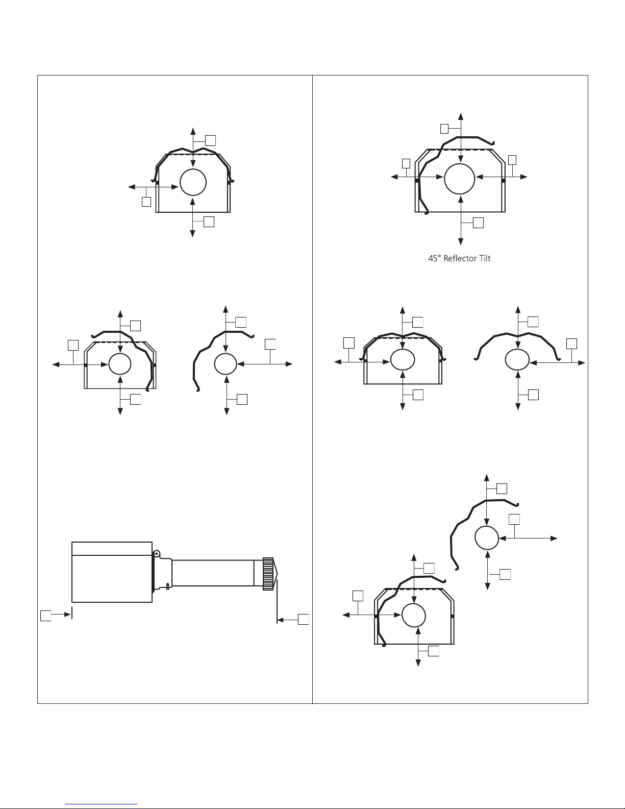
Figure 1: Clearances To Combustibles (Refer to TABLE 1 on page 4)
A
C
D
A
A
A
E
F
C
C
D
STANDARD REFLECTOR
STANDARD REFLECTOR
45 DEGREE REFLECTOR TILT
E
A
A
F
C
C C
U-TUBE OPPOSITE 45 DEGREE
“U”-Tube, Opposite 45°
A
F
EF
D
C
A
C
U-TUBE STANDARD
“U”-Tube, Standard
C
E
A
A
D
D
C
A
A
E
E
F
B
B
Front and Back Clearance
FRONT AND BACK CLEARANCE
E
E
B
A
C
C
“U”-Tube, Full 45°
U-TUBE FULL 45
C
Operating Instructions and Owner’s ManualEnerco | Heatstar ERXL Series Heater
E-5
Page 6
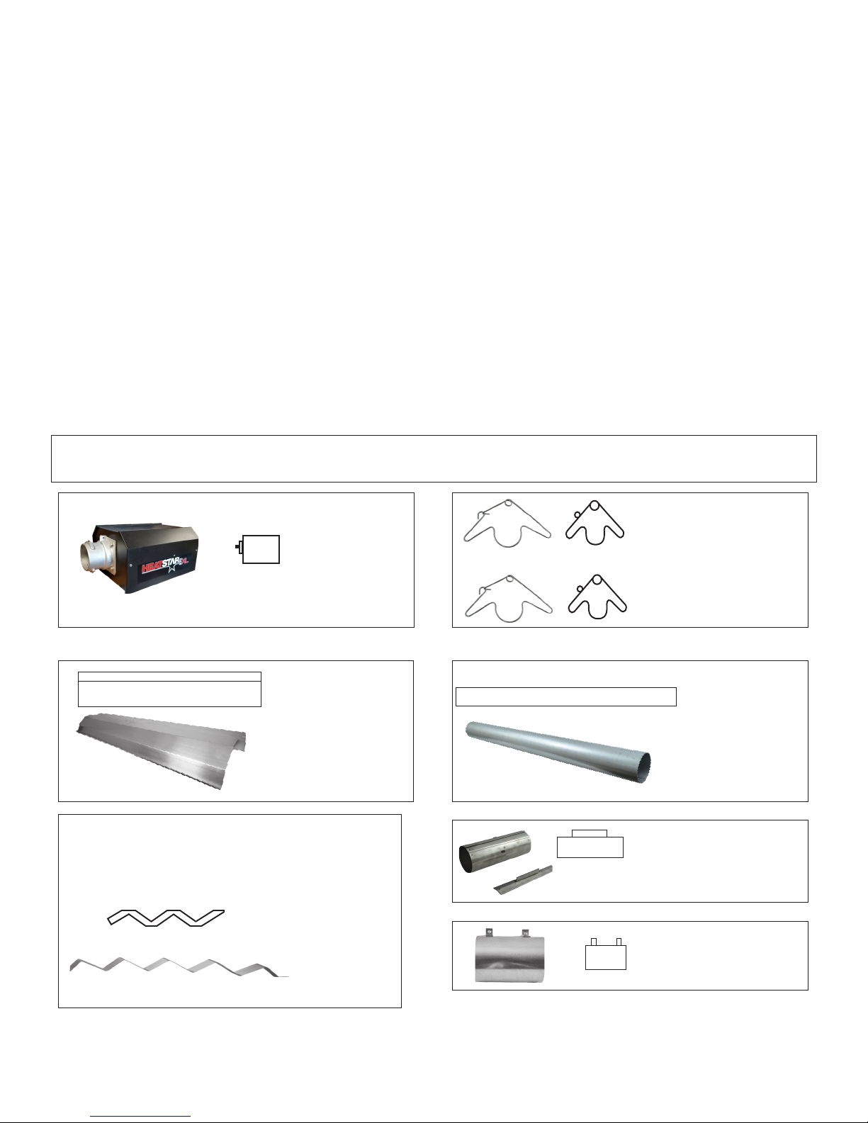
SECTION 3: Installation & Assembly
TUBE COUPLING(14612)
KEY FOR TUBE COUPLING
(14616)
BURNER BOX
TUBE HANGER
(14585P)
VENT ADAPTER
(19021)
REFLECTOR 10'
(00418A)
HEAT EXCHANGER TUBE 10'
(06413)
Enerco | Heatstar ERXL Series Heater Operating Instructions and Owner’s Manual
TURBULATOR BAFFLE 10' (03445)
TURBULATOR BAFFLE 5' (03447)
**NOT INCLUDED WITH ALL MODELS**
**ONLY HEATERS 30' LENGTH AND UNDER**
E-6
Page 7
installed, must be electrically grounded in accordance with the National Electrical Code, ANSI/ NFPA 70 or current Canadian Electrical
Code, CSA C22.1.
Installation Procedure
NOTE: For either indoor or outdoor installation. Not for use in residential dwellings.
Take maximum advantage of the building upper structure, beams, joists, purlins, etc., from which to suspend the heater. There is no
unique sequence for installation of the tubing. On-site observation will usually reveal a logical sequence. Begin the installation at the most
critical dimension. This could save time. Watch for swinging doors, overhead cranes, car lifts etc. Reflectors and tubing can be installed as
you move along. Carefully adjust system pitch at each position to level the heater. Pitch down one-half inch in 20 feet (away from burner).
DON’T Pressure test the gas line using high pressure (greater than ½ PSIG) without closing the high-pressure shutoff cocks. Failure to do so will
result in damage to the burners.
DO Familiarize yourself with local and national
codes.
Develop a planned procedure which will conserve material and labor on the job.
Check to see that all material and equipment is on the job before starting installation.
Allow for thermal expansion of the hot tube.
Install the gas connector only as shown in instructions (see Figure 14 on page 17).
Have slip joints where required between reflectors to keep them from buckling or coming apart.
Provide 1 sq. inch of free air opening to each 1,000 BTU/hr. of heater input (but not less than 100 sq. inches) in enclosed spaces. One
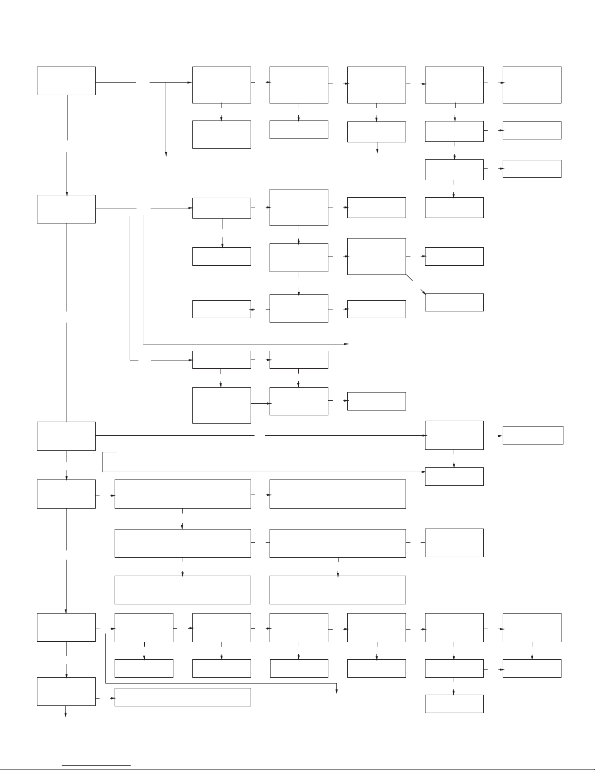
FIGURE 2: Ener-Radiant XL Overview
Assemble the heater components as shown in Figures 2A, 2B, 2C, 2D, 2E, 2F and 2G. Optional reflector configurations are shown in Figure
1. Install appropriated suspension hardware, beam clamps, chain or rod at predetermined locations. Adjustment of chain length will provide
uniform pitch.
Burner Housing
Must always be
installed horizontally.
10' 2-1/2"
Turbulator Assembly
Enerco Group, Inc normally ships Ener-Radiant heaters with
turbulators assembled into appropriate tubes.
Reflectors
Alternate overlap as shown
on overview. Length of
reflector and amount of
overlap is indicated.
Tube and Reflector Hanger
Install immediately after first
coupling.
Tube and Reflector Hanger
Suspend system from these hangers.
Minimum two (2) required per tube.
ALUMINIZED
Heat Exchange Tubes
Supplied in 10 ft. lengths.
Tube Coupling Assembly
Coupling should be oriented with
slide bar on top, and all couplings
should “point” in the same direction.
E-7
Vent Adapter
Used to attach the heat
exchanger tubing to vent pipe.
Operating Instructions and Owner’s ManualEnerco | Heatstar ERXL Series Heater
Page 8
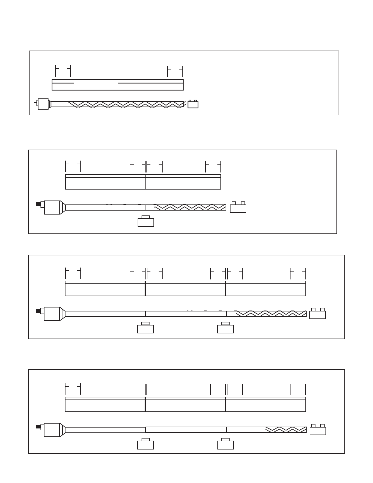
FIGURE 2A: Ener-Radiant XL Model ERXL-40
10 ft. Exchanger length. 11 ft. - 4 in. Total Heater length. 2 Suspension points as indicated.
HANGER
18"
(46cm)
HANGER
18"
(46cm)
10' 2½" (3.11m)
AL
UMINIZED
9' (2.75 m) Long Turbulator Section
FIGURE 2B: Ener-Radiant XL Model ERXL-60, ERXL-80, Assembly Overview
20 ft. Exchanger length. 21 ft. - 4 in. Total Heater length. 4 Suspension points indicated.
HANGER
18"
(46cm)
10' 2½" (3.11m)
ALUMINIZED
HANGER
(46cm)
18"
HANGER
18"
(46cm)
2½ OVERLAY TYP
10' 2½" (3.11m)
HANGER
18"
(46cm)
10' (3.05 m) Long Turbulator Section
FIGURE 2C: Ener-Radiant XL Model ERXL-80, Assembly Overview
30 ft. Exchanger length. 31 ft. - 4 in. Total Heater length. 6 Suspension points as indicated
HANGER
18"
(46cm)
HANGER
(46cm)
18"
HANGER
18"
(46cm)
HANGER
(46cm)
18"
HANGER
18"
(46cm)
10' 2½" (3.11m) 10' 2½" (3.11m) 10' 2½" (3.11m)
ALUMINIZED
FIGURE 2D: Ener-Radiant XL Model ERXL-100 Assembly Overview
30 ft. Exchanger length. 31 ft. - 4 in. Total Heater length. 6 Suspension points as indicated.
HANGER
18"
(46cm)
HANGER
(46cm)
18"
HANGER
18"
(46cm)
ALUMINIZED
HANGER
18"
(46cm)
HANGER
18"
(46cm)
10' 2½" (3.11m) 10' 2½" (3.11m) 10' 2½" (3.11m)
HANGER
18"
(46cm)
10' (3.05 m) Long Turbulator Section
HANGER
18"
(46cm)
ALUMINIZED
Enerco | Heatstar ERXL Series Heater Operating Instructions and Owner’s Manual
ALUMINIZED
5' (1.5 m) Long Turbulator Section
E-8
Page 9

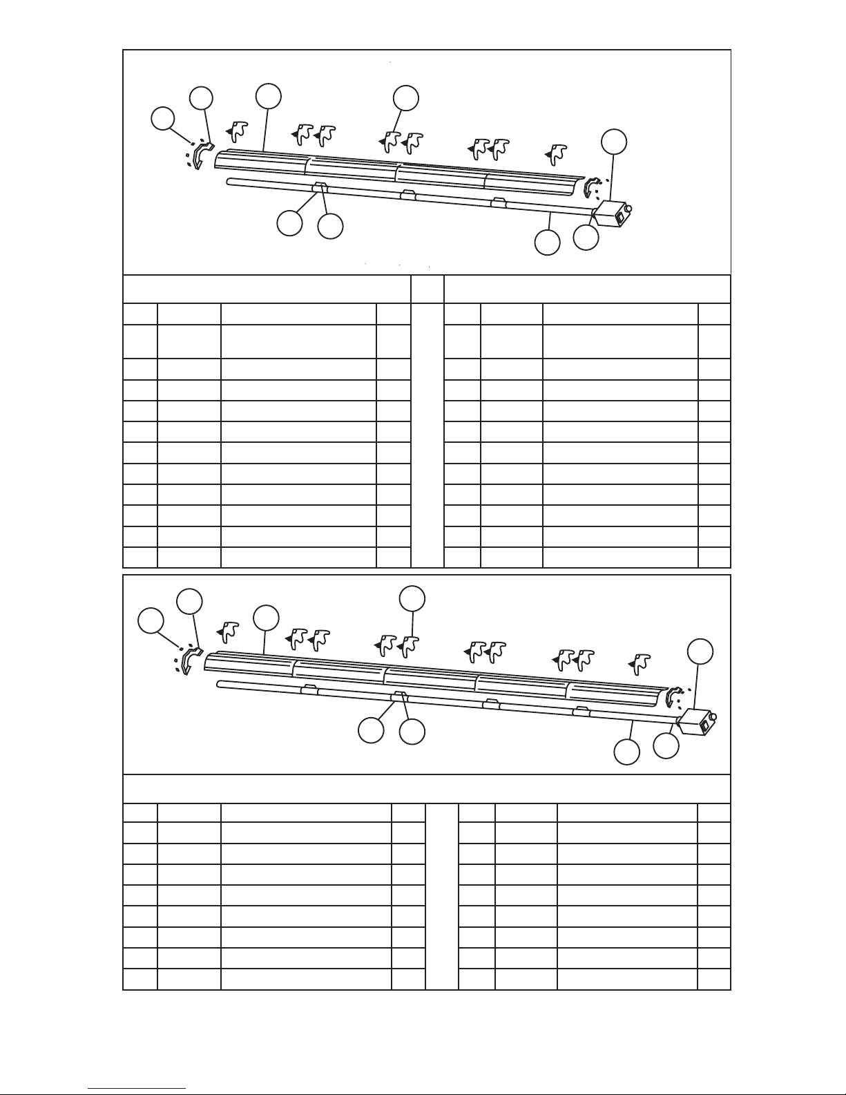
FIGURE 2E: Ener-Radiant XL Model ERXL-100, ERXL-125
40 ft. Exchanger length. 41 ft. - 4 in. Total Heater length. 8 Suspension points as indicated.
HANGER
18"
(46cm)
HANGER
10' 2½" (3.11m)
ALUMINIZED ALUMINIZED
18"
(46cm)
HANGER
18"
(46cm)
10' 2½" (3.11m) 10' 2½" (3.11m)
HANGER
18"
(46cm)
HANGER
18"
(46cm)
HANGER
10' 2½" (3.11m)
ALUMINIZED ALUMINIZED
18"
(46cm)
HANGER
18"
(46cm)
HANGER
(46cm)
FIGURE 2F: Ener-Radiant XL Model ERXL-125, ERXL-150, ERXL-175
50 ft. Exchanger length. 51 ft. - 4 in. Total Heater length. 10 Suspension points as indicated.
HANGER
18"
(46cm)
HANGER
10' 2½" (3.11m)
ALUMINIZED ALUMINIZED
18"
(46cm)
HANGER
18"
(46cm)
10' 2½" (3.11m) 10' 2½" (3.11m)10' 2½" (3.11m)
HANGER
18"
(46cm)
HANGER
18"
(46cm)
HANGER
10' 2½" (3.11m)
ALUMINIZED ALUMINIZED ALUMINIZED
18"
(46cm)
HANGER
18"
(46cm)
HANGER
(46cm)
18"
18"
HANGER
18"
(46cm)
HANGER
18"
(46cm)
FIGURE 2G: Ener-Radiant XL Model ERXL-150, ERXL-175
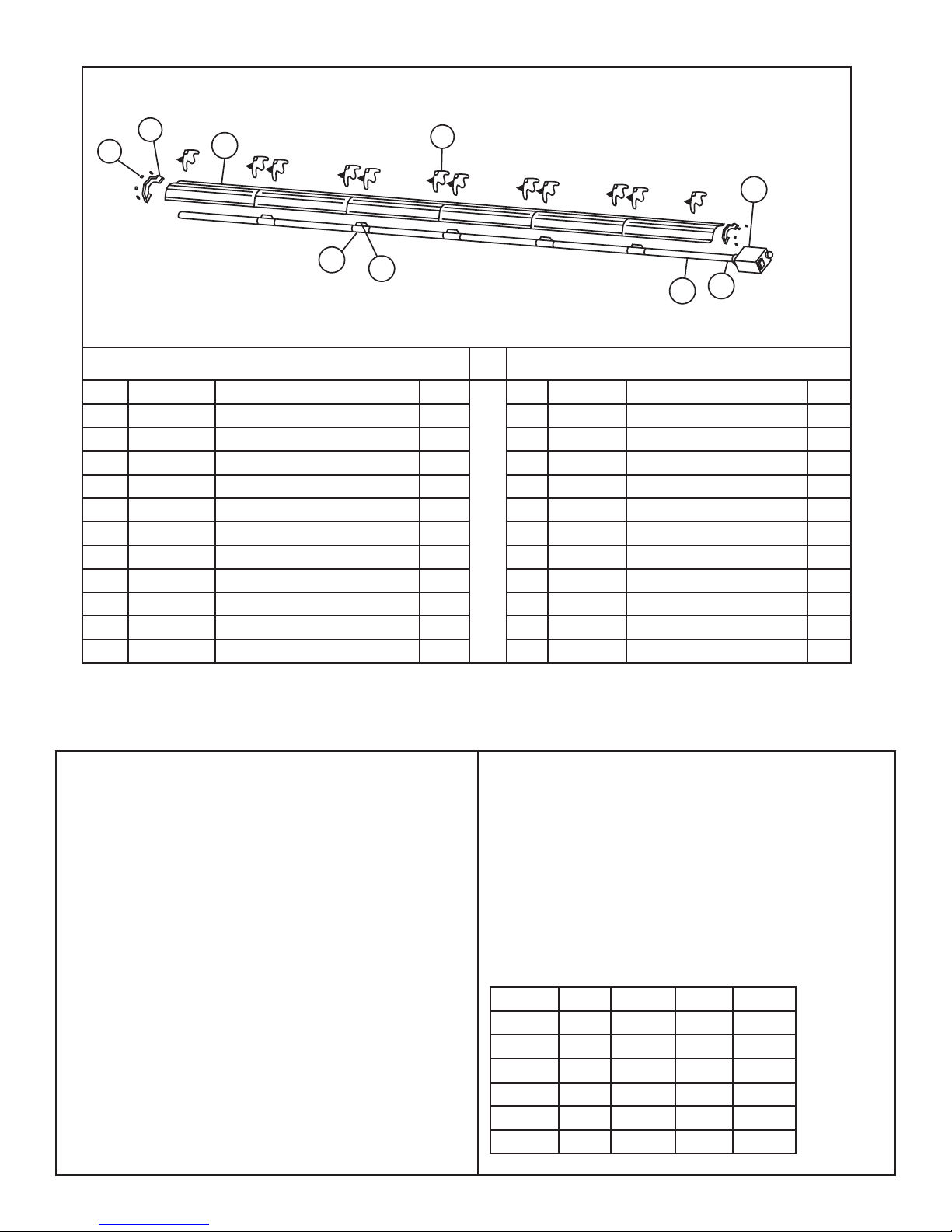
60 ft. Exchanger length. 61 ft. - 4 in. Total Heater length. 12 Suspension points as indicated.
HANGER
18"
(46cm)
HANGER
10' 2½" (3.11m)
ALUMINIZED ALUMINIZED
18"
(46cm)
HANGER
18"
(46cm)
10' 2½" (3.11m) 10' 2½" (3.11m)10' 2½" (3.11m)10' 2½" (3.11m)
HANGER
18"
(46cm)
HANGER
18"
(46cm)
HANGER
10' 2½" (3.11m)
ALUMINIZED ALUMINIZED ALUMINIZED ALUMINIZED
18"
(46cm)
HANGER
18"
(46cm)
HANGER
18"
(46cm)
HANGER
18"
(46cm)
HANGER
18"
(46cm)
HANGER
18"
(46cm)
HANGER
18"
(46cm)
E-9
Operating Instructions and Owner’s ManualEnerco | Heatstar ERXL Series Heater
Page 10
9.25"(23.49cm)
FIGURE 3: Ener-Radiant XL Dimensions & Suggested Mounting Heights
Minimum Total Length (see chart below)
Heat Exchanger Tubing
17.75"(45.08)
Reector
Turbulator
(some Models)
9.25"(23.49cm)
Burner Rear View
Burner Ratings and Heat Exchanger Lengths: (NG and LP) Suggested Mounting Heights
Model #
ERXL-40 40,000 10 ft. (3.05 m) 9 ft. (2.75 m)
ERXL-60 60,000 20 ft. (6.1 m) 10 ft. (3.05 m)
ERXL-80 80,000 20 ft. (6.1 m) 10 ft. (3.05 m) 21 ft. 4" (6.50 m) 12’ (3.66 m) - 15' (4.57 m)
ERXL-80 80,000 30 ft. (9.15 m) 10 ft. (3.05 m)
ERXL-100 100,000 30 ft. (9.15 m) 5 ft. (1.5 m)
ERXL-100 100,000 40 ft. (12.2 m) None
ERXL-125 125,000 40 ft. (12.2 m) None
ERXL-125 125,000 50 ft. (15.25 m) None
ERXL-150 150,000 50 ft. (15.25 m) None
ERXL-150 150,000 60 ft. (18.3 m) None
ERXL-175 175,000 50 ft. (15.25 m) None
ERXL-175 175,000 60 ft. (18.3 m) None
Rate
(BTU/Hr.)
Burner Side View
Heat Exchanger
Length
Turbulator
Minimum
Total Length
Typical Mounting
Height Spot
11 ft. 4" (3.45 m) 10’ (3.05 m) - 14' (4.27 m)
21 ft. 4" (6.50 m) 10’ (3.05 m) - 14’ (4.27 m)
31 ft. 4" (9.55 m) 12’ (3.66 m) - 15' (4.57 m)
31 ft. 4" (9.55 m) 12’ (3.66 m) - 15' (4.57 m)
41 ft. 4" (12.60 m) 12' (3.66 m) - 15' (4.57 m)
41 ft. 4" (12.60 m) 14' (4.27 m) - 19' (5.79 m)
51 ft. 4" (15.65 m) 14' (4.27 m) - 19' (5.79 m)
51 ft. 4" (15.65 m) 15' (4.57 m) - 25' (7.62 m)
61 ft. 4" (18.69 m) 15' (4.57 m) - 25' (7.62 m)
51 ft. 4" (15.65 m) 15' (4.57 m) - 25' (7.62 m)
61 ft. 4" (18.69 m) 15' (4.57 m) - 25' (7.62 m)
Enerco | Heatstar ERXL Series Heater Operating Instructions and Owner’s Manual
E-10
Page 11
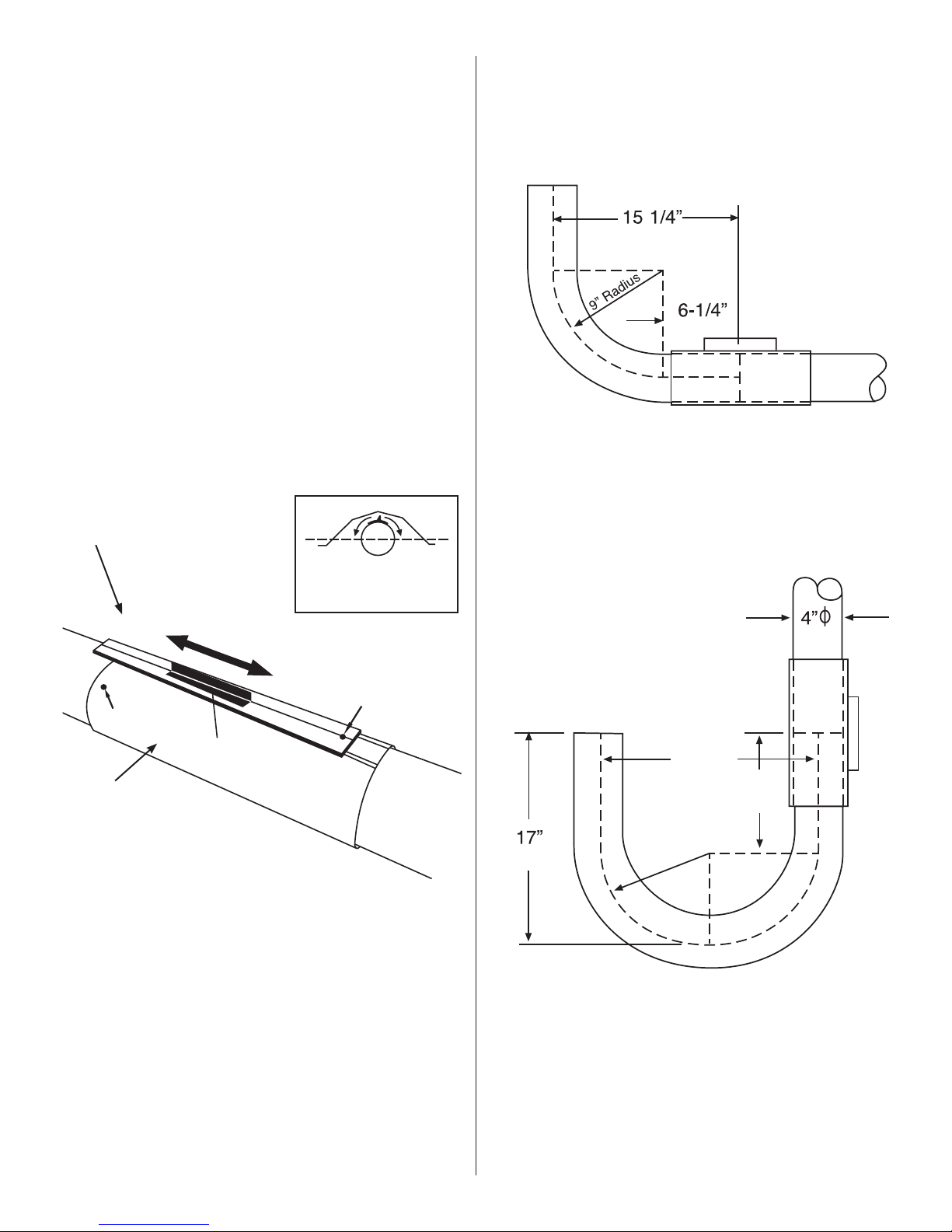
COUPLING ASSEMBLY
Couplings: Tube and tube fittings are connected by wrap-around
couplings which clamp by means of a tapered,
hammer-driven lock member. The starting ends of
the coupling and lock member are identified by 1/4”
holes which are put together when starting assembly.
Be sure the tube ends are in line and tube ends butt
against stop pin(s) inside coupling. The slide bar is to
be hammer-driven to a point of securing the coupling
snugly to the tubes. Over-driving will result in distortion
of the coupling or slide bar lip to a point decreasing
the holding the capability of the coupling.
(See Figure 4)
FIGURE 5: Installation of Elbow & Coupling
Elbow Package: Stk. # F106415 Elbow Package includes:
(1) elbow, (1) coupling. Install elbow
into radiant tube sequence where plans
indicate a 90° bend (see Figure 4).
(38.73 CM)
FIGURE 4:
KEY for COUPLING
Loosen
Hole 2
Impact
Block
TUBE COUPLING
When assembling coupling note
the location of Hole 1 and Hole 2
Orient coupling so that
the impact block is above
tube centerline.
Tighten
Hole 1
Coupling
Assembly
(22 cm)
90°
Elbow Fitting Dimensions
Stk. # i ncludes:F106414 U-Tube Package
(1) U-tube, (1) coupling
Install U-tube elbow into
radiant tube sequence where
plans indicate a 1800 bend
(see Figure 4)
(43cm)
(22cm)
9"
(15.24 CM)
(10cm)
18" (45cm)
10"
(25cm)
Radius
Plain Coupling - 14612
Key for Coupling - 14616
E-11
U-Tube Fitting Dimensions 180° U-Tube
Operating Instructions and Owner’s ManualEnerco | Heatstar ERXL Series Heater
Page 12
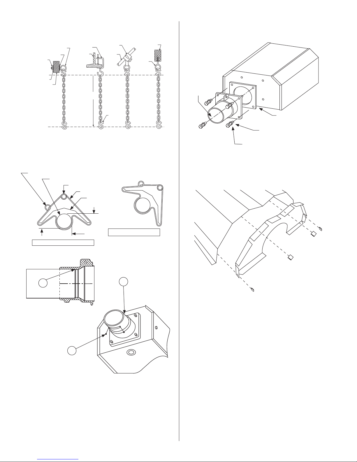
FIGURE 6: Typical Suspension Details
FIGURE 8: Burner Box / Transition Tube Detail
Screw Hook
min. 3/8" (10 mm)
Washer
Locknut
Beam
Clamp
I-Beam
Bar Joist
Clip
Truss
Concrete
Beam
Anchor
Washer
Wood Beam
As Req'd
S-Hook
Chain kit - Stk. #17370
One chain kit will suspend one 10 ft. section of tube and one 10 ft.
section of reflector.
FIGURE 7: Tube and Reflector Hanger
angle mounting ring
radiant tube
horizontal mounting ring
hanger
reflector
top
Burner Box
(flame observation
window facing down)
Mounting Flange
Gasket
Stk. #12397
Split Lock Washer
Stk. #98527
Cap Screw
Stk. 98012
Flange Kit #06428XL
Kit Includes: Flange,Screws(4), Lock Washers(4), Gasket(1)
FIGURE 9: Reflector End Cap
below
horizontal reflector position (standard)
A
side
B
45° reflector position (optional)
FIGURE 7: Mounting Flange / Tube Detail
1) Insert tube 06413 into front casting to point (A).
2) Tighter all set screws marked (B) until snug.
3) After both set screws are snug, turn each
additional 1/4 turn to secure tube in place.
B
Parts list
1 00419 Reflector End Cap (Qty 1)
2 09369 Spring Clip (Qty 4)
Enerco | Heatstar ERXL Series Heater Operating Instructions and Owner’s Manual
E-12
Page 13
SECTION 4
Engineering Specifications
The total heating system supplied shall be design certified by CSA
under ANSI Z83.20a latest revision and CGA 2.34a latest revision.
A. Burner & Burner Controls
1. Burners shall be capable of firing with one of the fuel options as
specified on the purchase documents: Natural Gas or LP.
2. Burners shall be supplied to fire at any one of the input rates as
specified.
ERXL-40 40,000 BTU/Hr. (11.72 kW)
ERXL-60 60,000 BTU/Hr. (17.58 kW)
ERXL-80 80,000 BTU/Hr. (23.45 kW)
ERXL-100 100,000 BTU/Hr. (29.31 kW)
ERXL-125 125,000 BTU/Hr. (36.63 kW)
ERXL-150 150,000 BTU/Hr. (43.96 kW)
ERXL-175 175,000 BTU/Hr. (51.29 kW)
3. Burner shall be equipped with a direct sense silicon-carbide hot
surface ignition control system with 100% shut-off ignition device.
Power supplied to each heater shall be 120V, 60Hz, single phase.
Burners shall be rated for 1.0 Amp (run) and 5.0 Amp (start.)
4. Burner shall be equipped with thermal overload motor
protection, balanced air rotor, combustion air proving safety
pressure switch, and viewing window for flame observation.
5. When specified, in contaminated environments, the burner
shall be capable of supplying outside air to each burner for the
support of combustion.
6. All burners shall be pre-wired with a grounded electrical
cord and plug.
7. At customer’s choice, burners may be controlled with either
an optional line voltage thermostat or by optional low voltage
thermostats with an appropriate low voltage transformer relay.
8. Gas supply to the burners shall conform to the following:
Gas pressure at MANIFOLD:
Natural Gas: 3.5” W.C. (0.87 kPa)
LP Gas: 10.5” W.C. (2.61 kPa)
1/2” NPT Gas Connector Size
Gas INLET pressure:
Natural Gas: 4.5” W.C. Min (1.12 kPa MIN)
11.0” W.C. Max (2.74 kPa MAX)
LP Gas: 11.0” W.C. Min (2.74 kPa MIN)
14.0” W.C. Max (3.48 kPa MAX)
1/2” NPT Gas Connector Size
Electrical Rating: (All Models)
120V - 60Hz
1.0 AMP (Run) 5.0 AMP (Start)
Dimensions:
Flue Connection Size…………………4” (10 cm)
Outside Air Connection Size………4” (10 cm)
1/2” NPT gas connector size
Natural Gas: 4.5” W.C. MIN, 11.0” W.C. MAX
(1.12 kPa MIN, 2.74 kPa MAX)
LP Gas: 11” W.C. MIN, 14.0” W.C. MAX
(2.74 kPa MIN, 3.48 kPa MAX)
B. Heat Exchanger
1. Radiant tubing shall be 4” (10 cm) diameter aluminized steel
supplied in 10 ft. sections (3.05 m). Sections shall be joined with
stainless steel wrap-around couplings.
2. Reflector to be of aluminum material and designed to direct all
radiant output below horizontal center line of radiant tube.
3. Heaters shall be vented according to manufacturer’s
recommendations.
E-13
Operating Instructions and Owner’s ManualEnerco | Heatstar ERXL Series Heater
Page 14
SECTION 5
Venting / Ducting
General Requirements
This heater must be vented in accordance with the specifications
contained in this manual and with the following national codes
and any state, provincial or local codes which may apply:
• Refer to National Fuel Gas Code NFPA 54/ANSI Z223.1- latest
revision.
• CANADA: Refer to Natural Gas and Propane Installation Code
CSA B149.1- latest revision.
The heater may be vented to the outdoors either vertically or
horizontally.
Optional outside air supply may be directed to the heater
horizontally or vertically.
Be sure that the method selected for venting heater complies with
all codes as required for each particular location
The use of single-wall vent pipe (26 gauge) is recommended. A
section of double-wall vent pipe is recommended when passing
through the roof or wall.
Exhaust end of heater will accept a 4' (10 cm) vent pipe using
the vent adapter. Install the vent adapter with the seam on top,
secure all vent joints with a minimum of 3 #8 x 3/8" sheet metal
screws and seal all joints using a high temperature silicone sealant.
If condensation in the flue is a problem, the flue length should be
shortened or insulated.
Vent pipe must be sloped downward away from the burner 1/4"
(0.6 cm) for ever 10' (3m).
VENT LENGTHS:
• Maximum total vent length allowed in thirty (30’) (9.15 m) feet.
• Maximum outside air supply duct allowed thirty (30’) (9.15 m) feet.
• Maximum total vent length plus outside air supply length shall not
exceed fifty (50’) (15.25 m) feet.
NOTE:
A total of two (2) elbows are allowed for vent and
outside air supply combination. Subtract 5' feet (1.5 m) per
additional elbow from maximum length allowed if 3 or more elbows
are used.
Install a minimum 18" (30 cm) straight length of duct for air intake
or vent before any Tee or elbow.
Alternative Arrangements / Optional Equipment for Venting
Unvented Operation
a) Sufficient ventilation must be provided in the amount of 4 CFM
per 1,000 BTU/hr. firing rate.
b) Refer to ANSI Z223.1 - latest revision, NFPA-54 and local codes
for additional information.
c) Use of optional outside combustion air is not recommended with
unvented heaters due to pressure considerations. Refer to page
16
Horizontal Venting
This heater, when horizontally vented, must be installed with the
approved venting system. For horizontal venting installations these
tube heater are certified as a category III appliance.
a) Four (4”) inch (10 cm) O.D. flue pipe is required. Thirty (30’)
(9.15 m) feet maximum length is recommended.
b) All flue joints should be sealed using suitable product such as
General Electric RTV106 or Permatex Form-A-Gasket Red High
Temperature Silicone Adhesive Sealant.
c) Do not install any elbow or 45 fitting to bring vent lower than
the horizontal tube system.
d) Vent terminal should be installed at a height sufficient to prevent
blockage by snow.
1) Vent must exit building not less than seven (7’) feet (2.13 m)
above grade when located adjacent to public walkways.
2) Vent must terminate at least three (3’) feet (.91 m) above
any forced air inlet located within ten feet (10’) (3.05 m).
3) Vent must terminate at least four (4’) feet (1.2 m) below,
four (4’) feet (1.2 m) horizontally from, or one (1’) foot
(30.5 cm) above any door, window, or gravity inlet into any
building.
4) Vent terminal shall be located at least twelve (12”) inches
(30.5 cm) from any opening through which vent gases could
enter the building.
5) Vent terminal must be beyond any combustible over hang
Vertical Venting
This heater, when vertically vented, must be installed with the
approved venting system. For vertical vent installations,
ERXL40-150 models are category I appliances. The ERXL175 model
is only Category I when vented vertically with 6" (15.25cm) diameter
vent pipe.
a) Four (4”) inch (10 cm) O.D. flue pipe, maximum thirty (30’) feet
(9.15 m) in length may be used as shown with approved vent
cap. (See General Requirements on this page for additional
information.)
b) An insulated thimble may be required to pass through
combustible structures (check local codes).
c) All flue joints should be sealed using suitable products (see
recommendation for horizontal venting.)
Common Venting
a) Horizontal run to vent must never exceed 75% of the vertical
height of the vent. Refer to ANSI Z223.1 - latest revision, NFA-54
for proper vent sizes and installation.
b) Open area of common vent must equal the sum of the open
area of individual vents connected to it. (See chart below and
diagrams - page 14.)
c) Use double wall vent as required (check codes.)
d) All joints must be sealed using suitable products.
e) Connections to common stack must be positioned to avoid direct
opposition between streams of combustion gases.
COMMON VENTING - (2) Heaters (Horizontal and Vertical)
Model #
ERXL-40
ERXL-60
ERXL-80
ERXL-100
ERXL-125
ERXL-150
ERXL-175
H = 6 ft. (1.82 m) H = 8 ft. (2.44 m) H = 15 ft. (4.57 m)
D = 7" (17.8 cm) D = 6" (15.25cm) D = 6" (15.25cm)
D = 7" (17.8 cm) D = 6" (15.25cm) D = 6" (15.25cm)
D = 8" (20.5 cm) D = 7" (17.8 cm) D = 6" (15.25cm)
D = 8" (20.5 cm) D = 8" (20.5 cm) D = 7" (17.8 cm)
D = 10" (25.4 cm) D = 10" (25.4 cm) D = 8" (20.5 cm)
D = 10" (25.4 cm) D = 10" (25.4 cm) D = 8" (20.5 cm)
D = 10" (25.4 cm) D = 10" (25.4 cm) D = 8" (20.5 cm)
Enerco | Heatstar ERXL Series Heater Operating Instructions and Owner’s Manual
E-14
Page 15
FIGURE 12: Common Roof Venting
VERTICAL COMMON VENTING
Approved Vent Cap
SIDE VIEW
Vent Adapter Stk. #19021
Burner Box Burner Box
HORIZONTAL COMMON VENTING
Flashing
H
Secure all joints with 3 (minimum) #8 x 3/8"
sheet metal screws and seal all joints.
D
D
Type "B" Vent required outdoors.
Roof
H
Vent Adapter Stk. #19021
Burner Box
Wall Thimble
(If Applicable)
Vent Cap
Type "B" Vent required outdoors.
Outside Wall
Secure all joints with 3 (minimum) #8 x 3/8"
sheet metal screws and seal all joints.
D
Burner Box
E-15
Operating Instructions and Owner’s ManualEnerco | Heatstar ERXL Series Heater
Page 16
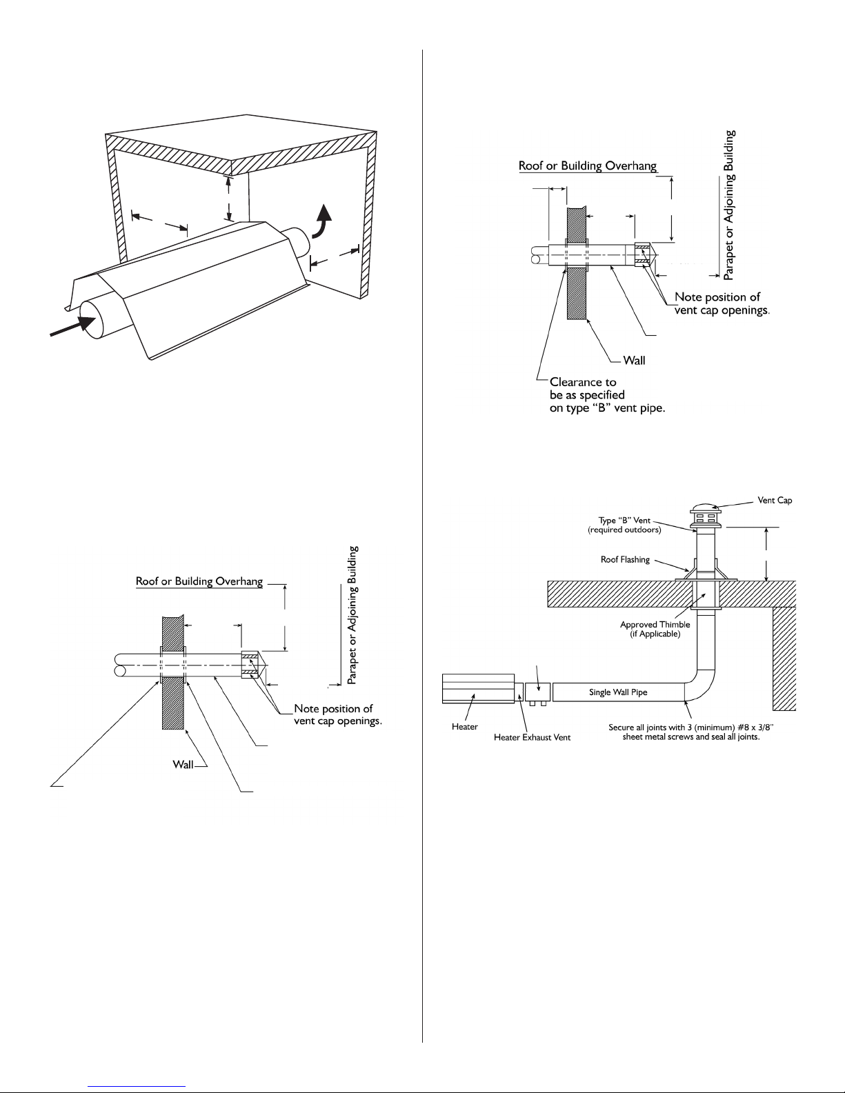
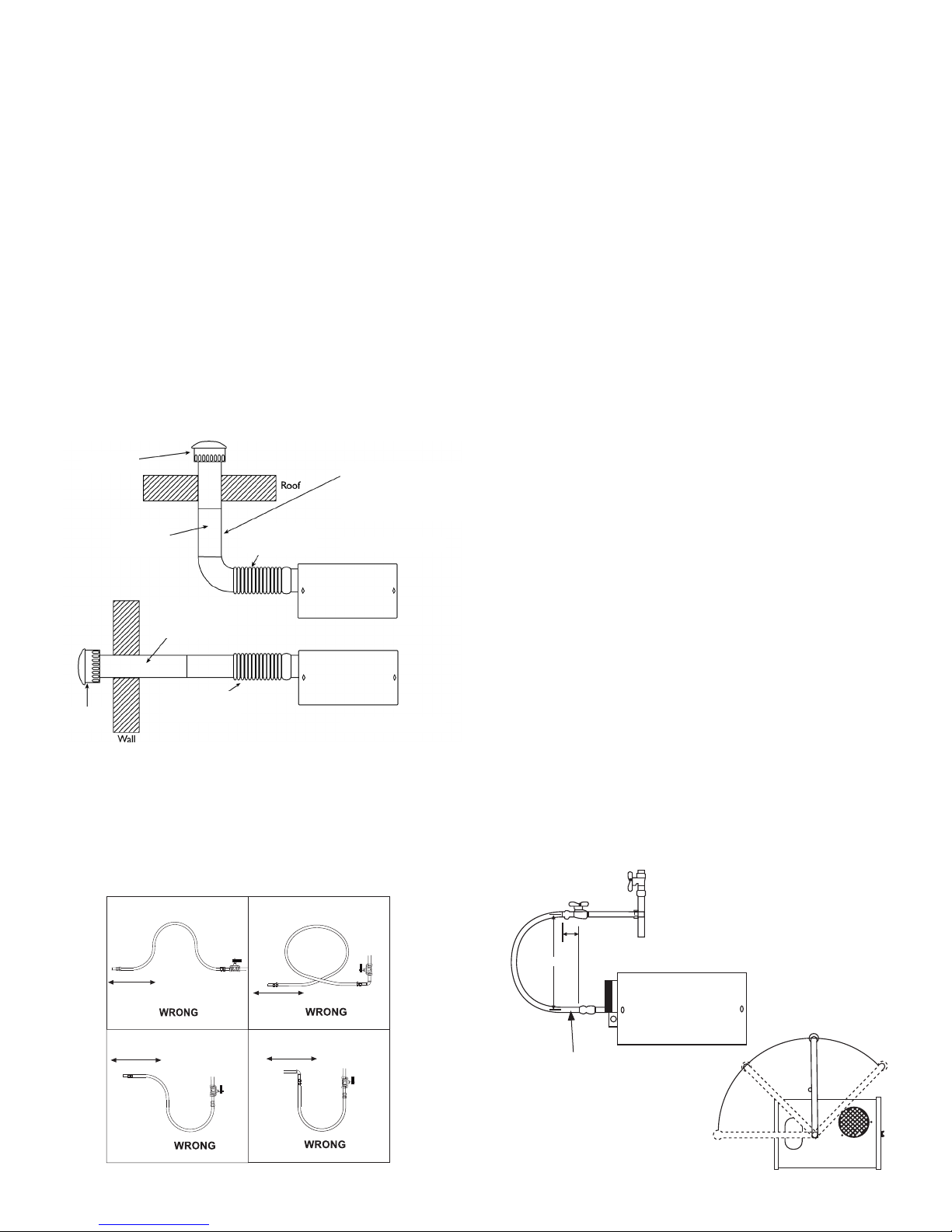
FIGURE 10: Unvented Operation
FIGURE 10b: Double Wall
Double wall vent run
Double wall terminal end
A
36”
(91cm)
36”
(91cm)
1. Ventilation equal to 4 CFM per 1,000 BTU/HR firing rate must
be provided in unvented heater installations
2. For dimensions A "unvented" refer to ( Figure 1- Minimum
Clearances to Combustibles.)
FIGURE 10A: Single Wall
Single wall vent run
Single wall terminal end
8"(20cm) to 10"(25cm) Max.
18" (45cm) Min. 3'-0" (91cm) Min.
6' (182cm) Min.
Pitch flue pipe down
toward outlet 1/4" per
foot (0.6 cm per 0.3m) for
condensate drainage.
FIGURE 11: Vertical Venting
18" (45cm)
2"(5cm) Clearance thimble
required when u pipe
extends through
combustible materials
18" (45cm) Min. 3'-0" (91cm) Min.
6' (182cm) Min.
Pitch flue pipe down
toward outlet 1/4" per
foot (0.6 cm per 0.3m) for
condensate drainage.
2"(5cm) Clearance thimble
Enerco | Heatstar ERXL Series Heater Operating Instructions and Owner’s Manual
E-16
Page 17
Outside Combustion Air Supply
The Ener-Radiant XL heater is approved for installation with an
outside air supply system. Some compounds such as halogenated
hydrocarbons or other corrosive chemicals in the air can be drawn
into the equipment and cause an accelerated rate of corrosion
of some of the heater components. The use of such chemical
compounds near the enclosure should be avoided.
IMPORTANT: If the building has a slight negative pressure or
contaminants are present in the air, an outside combustion air
supply to the heaters is strongly recommended.
For an outside air supply, a four (4”) inch (10 cm) O.D. single
wall pipe may be attached to the heater. The duct may be up to
thirty (30’) ft (9.15 m). maximum length or two (2’) ft. minimum
(0.61m) length with no more than two (2) elbows. (See General
Requirements on page 14 for additional information.)
The air supply duct may have to be insulated to prevent
condensation on the outer surface. The outside air terminal should
be securely fastened to the outside wall by drilling four (4) 1/4”
(0.635 cm) diameter holes in the outside flange; wood screws or
bolts and expansion sleeves may be used to fasten terminal.
FIGURE 13: Non-Pressurized Outside Air Supply Duct
Outside Air
Outside Air
Terminal
Terminal
4" (10 cm)
Seal All Joints
4" (10 cm)
Seal All Joints
Flex Pipe
6" (15 cm) to
12" (30 cm) Long
Flex Pipe
6" (15 cm) to
12" (30 cm) Long
NOTE:
Flue pipe requires additional
support. Flex pipe will not
support riser and outside
air terminal
Vertical Outside Air
Horizontal Outside Air
SECTION 6
Gas Piping
Read applicable warnings in (Section 1) before proceeding with
Gas Pipe installation. Improper installation may result in property
damage, severe injury, or death.
Meter and service must be large enough to handle all the burners
being installed plus any other connected load. The gas line which
feed the system must be large enough to supply the required gas
with a maximum pressure drop of 1/2” water column (0.12 kPa).
When gas piping is not included in the layout drawing, the local gas
supplier will usually help in planning the gas piping.
A 1/2” tapping at each burner location must be located and
oriented as shown in (Figure 14). To check system pressure, put a
plugged 1/8” NPT tapping in the gas line at the connection to the
burner farthest from the supply. Before connecting the burners to
the supply system, verify that all high pressure testing of the gas
piping has been completed. Do not high pressure test the gas piping
with the burners connected.
Follow these instructions to ensure a professional gas supply
installation:
• Support all gas piping with suitable pipe hanging
materials.
• Use wrought iron or wrought steel pipe and malleable
iron fitting. All pipe fittings should be new and free
from defects. Carefully ream the pipe and tubing ends
to remove obstructions and burrs.
• Use L.P. gas-resistant joint compound on all pipe
threads.
• Check the pipe and tubing ends for leaks before
placing heating equipment into service. When
checking for gas leaks, use soap and water solution:
NEVER USE AN OPEN FLAME.
Install the flex gas connector as shown. The flex gas connector
accommodates expansion of the heating system and allows for easy
installation and service of the burner.
PVC Pipe, “Dryer Hose”, or equivalent may be used instead of
standard vent pipe.
FIGURE 14A: Incorrect Gas Line Connection with Stainless
Steel Flex Gas Connector
Heater Movement
Heater Movement
Heater Movement
Heater Movement
FIGURE 14: Gas Line Connection with Stainless Steel Flex Gas
Connector
Shut – off Valve
Shut-Off Valve must be parallel
to burner gas inlet. The 2” (5 cm)
displacement shown is for the cold
condition. This displacement may
reduce when the system is fired.
45°
90°
E-17
2"
12 "
1/2" Stainless Steel Flex Gas Connector
Stk. #16401
Operating Instructions and Owner’s ManualEnerco | Heatstar ERXL Series Heater
0°
45°
Page 18

SECTION 7
T
H
N
120v – 60 Hz
White
Green
Supply Circuit
Burners
(Maximum – 2 per Thermostat)
Black
T
H
N
120v – 60 Hz
White
Green
Supply Circuit
Burners
(Maximum – 2 per Thermostat)
Black
Wiring
Heaters are normally controlled by thermostats. Line voltage
thermostats are wired directly (see Figure 15), 24V thermostats
are wired directly by finding and removing the jumper wire on the
back of the burner box and wiring the thermostat to the terminals
(see Figure 16). Heaters must be grounded in accordance with the
National Electric Code ANSI/NFPA- 70 or current Canadian Electrical
Code, CSA C22.1. Heaters may also be controlled with a manual line
voltage switch or timer switch in place of the thermostat.
FIGURE 15: Line Voltage Thermostat Wiring
FIGURE 18: Ener-Radiant XL Burner Internal Wiring Ladder
Diagram
L2
(NEUTRAL)
White
Orange
120V
24V
Transfomer
Blue
Thermostat
L2 (HOT)
Black
FIGURE 16: Low Voltage Thermostat Wiring
(Maximum – 1 per Thermostat)
H
N
120v – 60 Hz
Supply Circuit
Black
White
Green
FIGURE 17: Ener-Radiant XL Burner Internal Wiring
• If any of the original wire as supplied with the
appliance must be replaced, it must be replaced with
wiring material having a temperature rating of at
least 105°C and 600 volts.
• Each burner must be electrically grounded in
accordance with the National Electric Code ANSI/
NFPA - 70 or current Canadian Electrical Code, CSA
C22.1.
Transformer
120V
White
120
Black
VAC
Green
Green
Black
Motor / Blower
Door Switch
Black
White
24V
Blue
THERMOSTAT
White
Black
Terminal
Bushing
Orange
Purple
Black
Sensor
Enerco | Heatstar ERXL Series Heater Operating Instructions and Owner’s Manual
Burners
Gas Valve
White
Ignitor
Air Switch
Yellow
Purple
White
Ignitor
Sensor
White
Door Switch
Black
Black
Motor / Blower
Gas Valve
White
Black
White
Yellow
White
Gray
SECTION 8
T
Operation & Maintenance
Sequence of Operation
1. Turn the thermostat up. When the thermostat calls for heat,
blower motor will energize.
2. When the motor approaches nominal running RPM, the air
proving switch closes and activates the ignition module.
3. The ignition module then energizes the hot surface igniter for a
timed warm-up period (approximately 45 to 60 seconds.)
4. After the warm-up period, the gas valve is energized.
5. During the last part of the sequence, the igniter is de-energized
and is converted to a flame sensing rod.
6. If a flame is detected, the gas valve remains open. When the
call for heat is satisfied, and the system control mechanism
de-energizes the burner line voltage supply, the gas valves are
Yellow
Yellow
Air Switch
E-18
turned off.
7. If no flame is detected on a single-try module, the gas valve
is closed, and the module will lockout until it is reset. Reset is
accomplished by removing power from the module for at least
five (5) seconds (thermostat cycle required.)
8. If no flame is detected on a three-trial module, the gas valve is
closed, and a purge period begins. After the purge, the module
acts to power the igniter for a second warm-up period, and a
second trial for ignition period. If flame is still not established, a
third and final purge, warm-up, and trial cycle begins. After three
trials, the module will lockout until reset. Reset is accomplished
by removing power from the module for at least five (5) seconds
(thermostat cycle required.)
9. On a three-trial module, if flame is established and lost on the
first or second trial, the gas valve is turned off, a purge, warm-up,
and trial for ignition will occur on a three-trial module, only three
trials for ignition are allowed per thermostat cycle.
Page 19
HIGH ALTITUDE
Heaters may be fired at full input up to 2000 ft. (610m) above sea
level. Above 2000 ft. (610m) a high altitude conversion kit may be
required to ensure proper burner performance, please consult the
manufacturer. Be prepared to answer factory questions regarding:
type of fuel for the proposed appliance conversion, gas pressure
available at site, and specific altitude at site. The conversion shall
be carried out by a manufacturer’s authorized representative, in
accordance with the requirements of the manufacturer, provincial,
or territorial authorities having jurisdiction and in accordance with
the requirements of the CSA B149.1 or CSA149.2 installation codes.
Maintenance
For best performance, the following maintenance procedures should
be performed before each heating season:
1. Be sure gas and electrical supply to heater are off before
performing any service or maintenance.
2. Check condition of blower scroll and motor. Dirt and dust
may be blown out with compressed air, or a vacuum cleaner
may be used. When using compressed air do not exceed 30
psi in order to not damage fragile hot surface igniter.
3. Check condition of burner. Carefully remove any dust or
debris from inside the burner box or burner cup.
4. Inspect the igniter. Replace igniter if there is excessive carbon
residue, erosion, breakage or other defects.
5. Check the inside of the firing tube with a flashlight. If carbon
or scale are present, scrape out the deposits with a wire
brush or rod, or metal plate attached to a wooden pole.
6. Check to see that the burner observation window is clean
and free of cracks or holes. Clean or replace as necessary.
7. Check the flue pipe for soot or dirt. After cleaning as
necessary, re-attach the flue pipe to the heater.
8. Outside surfaces of heater may be cleaned by wiping with a
damp cloth.
9. A qualified service agency should be contacted for service
other than routine maintenance.
10. Check vent terminal and fresh air inlet to see that they have
not been blocked during the non-heating season. If either
pipe is restricted, the air switch won’t close, resulting in a
no-heat situation.
Troubleshooting
CAUTION: Before opening the Ener-Radiant XL
burner door for any type of service, be sure
the gas supply has been shut off at the heater
and the electrical cord from the burner box
has been unplugged.
Blower Motor 1. Is the thermostat calling for heat? Is there
Fails to Run: 115V at the burner receptacle?
2. Check blower side door for seal. Check
door switch. Replace if necessary.
3. Check blower for obstructions. Replace
blower if necessary.
Igniter 1. Check igniter for damage. Replace if
Does Not Glow: necessary.
2. Check voltage and resistance at igniter.
(Voltage should be 115V. Resistance should
be 40-75 ohms.)
3. Check for obstructions to the air inlet and
outlet.
4. Check wiring and hose connections to the
air switch. Replace if necessary.
5. Check voltages at transformer primary and
secondary. Replace transformer or module
if necessary.
Valve Does Not Gas pressure downstream of gas control can
Come On: be measure by using a manometer and
connecting to pressure tap on control/.
1. Check to see if manual valve heater is ON.
2. Check to see if manual valve knob on
heater gas control in ON.
3. Supply gas pressure can be checked at 1/8”
NPT pressure tapping on heater external
manual valve.
4. Check to see if gas control is opening: no
manifold pressure indicates valve is closed.
If the valve is closed, either the gas valve or
the ignition module is faulty.
WARNING: Do not disconnect ground leads
inside heater. Do not interchange grounded
and ungrounded leads on transformer or
ignition module.
Burner Does Not 1. Check to see if gas lines were properly
Light: purged of air.
2. Check inlet and outlet gas pressure during
ignition period.
• Natural inlet pressure should be 4.5” (1.12 kPa)
• Natural outlet pressure at manifold should be 3.5” (0.87 kPa)
• LP inlet pressure should be 11.0” (2.74 kPa)
• LP outlet pressure at manifold should be 10.5” (2.61 kPa)
3. Check for proper orifice and air plate.
E-19
Operating Instructions and Owner’s ManualEnerco | Heatstar ERXL Series Heater
Page 20
Burner Does Not 1. Check ground wire continuity.
Stay Lit: 2. Check burner internal wiring for reversed
leads.
3. Check insulation on the igniter leads.
4. Replace module if necessary.
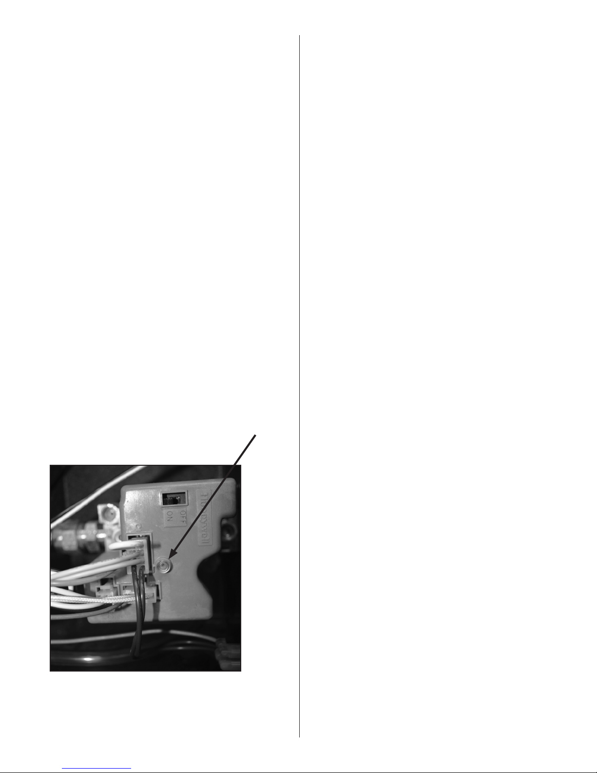
Honeywell Valve LED Status
The Ener-Radiant XL series Tube Heater is equipped with a
honeywell Smart Valve. This valve has a built-in diagnostic program,
which will assist in troubleshooting in the event of a valve-related
problem. The LED or (Light Emitting Diode) is located on the top of
the valve as shown in diagram below. The LED status indications are
listed below to help with the troubleshooting.
FIGURE 19:
OFF INDICATED
Off No power to the control
Bright-Dim Normal operation.
This indication shows whenever the system is
powered, unless some abnormal event has occurred.
2-Flashes Airflow providing switch remains closed longer than
30 seconds after call for heat begins (air providing
switch stuck closed.)
3-Flashes Airflow providing switch remains open longer than 30
seconds after combustion air blower is energized - or
blower does not energize.
4-Flashes White jumper wire is loose.
5-Flashes Flame signal sensed out of proper sequence.
6-Flashes System Lockout.
Honeywell Smart Valve
LED
Enerco | Heatstar ERXL Series Heater Operating Instructions and Owner’s Manual
E-20
Page 21
SECTION 9: Troubleshooting Guide. Ener-Radiant XL
START
Turn on thermostat
Does blower turn
on?
Yes
Does the igniter
warm up and glow
red?
Yes
No
Check LED indicator on SmartValve for
indication of fault. Refer to SmartValve testing
on page 20 to determine problem.
No
Check Thermostat
and Wiring. Is the
power supply to unit
115V?
No
Find the source
of the electrical
problem
Is the air intake or
exhaust blocked?
Yes
Remove Obstruction
Check wiring and
connections
Is blower side door
Yes
No
No
in place?
Replace door
Check wiring and
hose connection to
air switch. Are they
Is the voltage at
the transformer
secondary 24V?
Is the voltage at the
transformer primary
Yes
No
Check for 115V transformer input at plug
C3 on SmartValve. Check for 115V output
of C3. If no output voltage is present
replace SmartValve.
Replace wiring and/
No
or hose connection.
OK?
Yes
Yes
No
115 V
Remove door. Is
voltage at door
switch 115V?
No
Check voltage at
gas valve.
Jumper wires at
pressure switch.
Does the ignitor
glow red?
Replace transformerYes
Depress switch.
Yes
Does blower come
Check voltage to
motor. Is it 115V?
Is the blower fan
obstructed?
Replace blower
Replace pressure
Yes
No
Replace SmartValve.
on?
No
Yes
No
motor.
switch.
Check door fit. If
Yes
damaged, replace
Replace switch.
No
Remove obstruction
Yes
door.
After ignitor warm-
up period, does the
valve click?
Yes
Does the burner
light?
Yes
Check LED indicator on SmartValve for
indication of fault. Refer to SmartValve testing
No
The SmartValve checks the status of the blower proving switch contacts must see a change in the
contact with every firing cycle. Placing a jumper at the switch out of sequence will result in a fault with
No
Were the gas lines purged of air?
Check inlet gas pressure. Is pressure correct?
Refer to page 13 for correct pressure for unit.
Check inlet gas shutoff. Adjust regulator.
Contact gas supplier
Is the ignitor
damaged?
No
Check voltage at
ignitor. Is it 115V
during ignition
cycle?
the LED indicator flashing two times.
Yes
Yes
Replace ignitor.
Yes
No
Is the resistance
through igniter 40
to 75 ohms?
No
The switch on the gas valve must be in the on
No
Yes
position and the line purged of air.
Check outlet gas pressure during ignition cycle.
Is the pressure 3.5” w.c. for natural or 10.5”
w.c. for lp?
Adjust to proper pressure.
Yes
No
Check wire
connections.
on page 21 to determine problem.
Are the wires to
the SmartValve OK?
Yes
Replace SmartValve
Check for proper
Yes
burner orifice and
air plate.
Replace/repair wires.
No
Does the burner
stay on?
Yes
Does the burner
run until the call
for heat ends?
If a problem still exists, contact Enerco Group, Inc Technical Products
Is the continuity of
the ground wire
No
No
Customer Service 1-866-447-2194
OK?
No
Repair wiring.
Check the continuity of the ground wire.
Yes
Check the thermostat.
Are L1 and L2
reversed?
Yes
Repair wiring
Is the wiring at the
No
SmartValve OK?
No
Repair wiring
A fault indication of six flashes may indicate
that the flame sensing circuit is not functioning
properly. Perform the following series of checks
to correct the problem.
Operating Instructions and Owner’s ManualEnerco | Heatstar ERXL Series Heater
E-21
Is the insulation on
Yes
the sensor lead OK?
Repair wiring
No
Is the sensor
positioned
Yes
Is the sensor dirty?
Replace Sensor
properly?
Yes
No
No
Yes
Repair/Replace
Yes
Clean sensor.
Page 22

Parts List for Ener-Radiant XL Tube Heaters
7
3
5
8
1
4
2
6
ERXL-40
Item Stock # Description QTY Item Stock# Description QTY
1 F102594XL ERXL-40 NG / BRN & Cont Box 1 6 02753 Front Flange 1
1 F102595XL ERXL-40 LP / BRN & Cont Box 1 7 00 419 Reflector End Cap 2
2 F106408XL Tube Set- 10' 1 8 09369 Spring Clips 8
06413 Tube H.E. 4" O.D. X 10' 2
3 00418A Reflector 2
4 03445 Turbulator Baffle 9' 1
5 14585P Hanger 4
5
3
9
10
1
4
7
8
2
ERXL-60
Item Stock # Description QTY Item Stock# Description QTY
1 F102650XL ERXL-60 NG / BRN & Cont Box 1 1 F102652XL ERXL-80 LP / BRN CONT Box 1
F102651XL ERXL-60 LP / BRN & Cont Box 1 F102653XL ERXL-80 NG / BRN CONT Box 1
2 F106404XL ERXL-60, / Tube Set- 20' 1 2 F106404XL ERXL-80, / Tube Set- 20' 1
06413 Tube H.E. 4" O.D. X 10' 2 06413 Tube H.E. 4" O.D. X 10' 2
3 00418A Reflector 2 3 00418A Reflector 2
4 03445 Turbulator Baffle 10' 1 4 03445 Turbulator Baffle 10' 1
5 14585P Hanger 4 5 14585P Hanger 4
6 02753 Front Flange 6 02753 Front Flange
7 14 612 Tube Coupling 1 7 14 612 Tube Coupling 1
8 14 616 Key for Tube Coupling 1 8 14 616 Key for Tube Coupling 1
9 0 0 419 Reflector End Cap 2 9 0 0419 Reflector End Cap 2
10 09369 Spring Clips 8 10 09369 Spring Clips 8
6
ERXL-80
Enerco | Heatstar ERXL Series Heater Operating Instructions and Owner’s Manual
E-22
Page 23
9
3
5
10
1
4
8
7
2
6
ERXL-80
Item Stock # Description QTY Item Stock# Description QTY
1 F102652XL ERXL-80 NG / BRN & Cont Box 1 6 02753 Front Flange 1
F102653XL ERXL-80 LP / BRN & Cont Box 1 7 14 612 Tube Coupling 2
2 F106405XL ERXL-80, / Tube Set- 30' 1 8 14 616 Key for Tube Coupling 2
06413 Tube H.E. 4" O.D. X 10' 3 9 0 0419 Reflector End Cap 2
3 00418A Reflector 3 10 09369 Spring Clips 8
4 03445 Turbulator Baffle 10' 1
5 14585P Hanger 6
9
3
5
10
1
4
8
7
2
6
ERXL-100
Item Stock # Description QTY Item Stock# Description QTY
1 F102654XL ERXL-100 NG / BRN & Cont Box 1 6 02753 Front Flange 1
F102655XL ERXL-100 LP / BRN & Cont Box 1 7 14 612 Tube Coupling 2
2 F106401XL ERXL-100, / Tube Set- 30' 1 8 14 616 Key for Tube Coupling 2
06413 Tube H.E. 4" O.D. X 10' 3 9 0 0419 Reflector End Cap 2
3 00418A Reflector 3 10 0 9369 Spring Clips 8
4 03447 Turbulator Baffle 5' 1
5 14585P Hanger 4
E-23
Operating Instructions and Owner’s ManualEnerco | Heatstar ERXL Series Heater
Page 24
9
6
7
8
1
4
5
3
2
ERXL-100
Item Stock # Description QTY Item Stock# Description QTY
1 F102654XL ERXL-100 NG / BRN & Cont
F102655XL ERXL-100 LP / BRN & Cont Box 1 F102657XL ERXL-125 LP / BRN & Cont Box 1
2 F106406XL ERXL-100, / Tube Set- 40' 1 2 F106406XL ERXL-125, / Tube Set- 40' 1
06413 Tube H.E. 4" O.D. X 10' 4 06413 Tube H.E. 4" O.D. X 10' 4
6 02753 Front Flange 1 3 02753 Front Flange 1
4 14 612 Tube Coupling 1 4 14 612 Tube Coupling 1
5 14 616 Key for Tube Coupling 1 5 14616 Key for Tube Coupling 1
6 00418A Reflector 4 6 00418A Reflector 4
7 14585P Hanger 8 7 14585P Hanger 8
8 0 0 419 Reflector End Cap 2 8 0 0419 Reflector End Cap 2
9 09369 Spring Clips 8 9 0 9369 Spring Clips 8
Box
9
8
6
1 1 F102656XL ERXL-125 NG / BRN & Cont
7
ERXL-125
1
Box
1
Item Stock # Description QTY Item Stock# Description QTY
1 F102656XL ERXL-125 NG / BRN & Cont Box 1 3 02753 Front Casting 1
1 F102657XL ERXL-125 LP / BRN & Cont Box 1 4 14 612 Tube Flange 2
1 F102658XL ERXL-150 NG / BRN & Cont Box 1 5 14 616 Key for Tube Coupling 2
1 F102659X L ERXL-150 LP / BRN & Cont Box 1 6 00418A Reflector 5
1 F102660XL ERXL-175 NG / BRN & Cont Box 1 7 14585 Hanger 10
1 F102661XL ERXL-175 LP / BRN & Cont Box 1 8 0 0419 Reflector End Cap 2
2 F106407XL Tube Set- 50' 1 9 09369 Spring Clips 8
06413 Tube H.E. 4" O.D. X 10' 3
Enerco | Heatstar ERXL Series Heater Operating Instructions and Owner’s Manual
4
5
ERXL-125 / ERXL-150 / ERXL-175
E-24
3
2
Page 25
8
9
6
7
1
4
5
3
2
ERXL-150 ERXL-175
Item Stock # Description QTY Item Stock# Description QTY
1 F102658XL ERXL-150 NG / BRN & Cont Box 1 1 F102660XL ERXL-175 NG / BRN & Cont Box 1
1 F 102659XL ERXL-150 LP / BRN & Cont Box 1 1 F102661XL ERXL-175 LP / BRN & Cont Box 1
2 F106403XL Tube Set- 60' 1 2 F106403XL Tube Set- 60' 1
06413 Tube H.E. 4" O.D. X 10' 6 06413 Tube H.E. 4" O.D. X 10' 6
3 02753 Front Flange 1 3 02753 Front Flange 1
4 14 612 Tube Coupling 5 4 14 612 Tube Coupling 5
5 14616 Key for Tube Coupling 5 5 14 616 Key for Tube Coupling 5
6 00418A Reflector 6 6 00418A Reflector 6
7 14585 P Hanger 12 7 14585P Hanger 12
8 0 0419 Reflector End Cap 2 8 0 0 419 Reflector End Cap 2
9 0 9369 Spring Clips 8 9 09369 Spring Clips 8
ACCESSORY PARTS LIST
Stock Number Description
10371 ................................... Thermostat 24 volt
10392 ................................... Thermostat 110Volt
17370 ................................... Chain Kit
16401 .................................. 24” Stainless Steel Flexible
16405 .................................. 1/2"x24" 3/4" Stainless Steel
F106414 ............................... 180° U-Tube Accessory Kit
F106415 ............................... 90° Elbow Accessory Kit
19021 ................................... Vent Adaptor
06430 .................................. Vent Cap
00 438 .................................. Side Reflector kit
01376 ................................... Deflector kit (5')
19031 ................................... Turnbuckle 5/16"-18"
INSTALLATION KITS
F111751…………Installation kit for 20’ tube heater
F111752…………Installation kit for 30’ tube heater
F111753…………Installation kit for 40’ tube heater
F111754…………Installation kit for 50’ tube heater
F111755…………Installation kit for 60’ tube heater
Installation kit includes:
24-volt thermostat, vent cap, 24” stainless steel flexible gas
connector, gas shutoff valve, and chain kits required to hang heater.
CONVERSION KITS
ERXL-40
ERXL-60
ERXL-80
ERXL-100
ERXL-125
ERXL-150
ERXL175
117 32 LP TO NG 117 33 NG TO LP
117 34 LP TO NG 117 35 NG TO LP
117 36 LP TO NG 117 37 NG TO LP
117 38 LP TO NG 117 39 NG TO LP
117 4 0 LP TO NG 11741 NG TO LP
117 30 LP TO NG 117 31 NG TO LP
E-25
Operating Instructions and Owner’s ManualEnerco | Heatstar ERXL Series Heater
Page 26
2740
26
25
45 46
24
47
23
3
15-
21
42
43
41
22
44
14
13
12
7-9
6
5
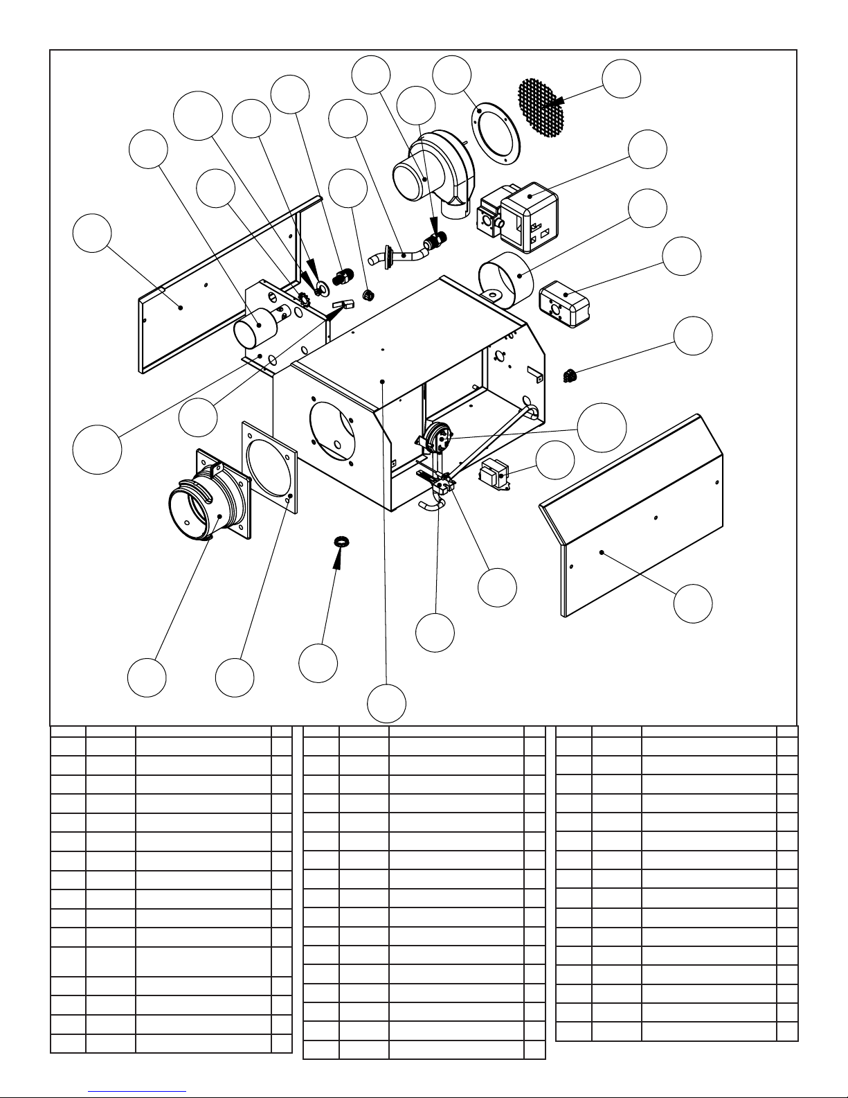
ITEM# EGI # DESCRIPTION QTY
1 02716XL ENCLOSURE
2 02725XL CONTROL SIDE COVER
3 02749XL MOTOR SIDE COVER
4 12397 FRONT FLANGE GASKET
5 02753 FRONT TUBE FLANGE
6 08364A TRANSFORMER
7 02836 40K PRESSURE SWITCH
8 10 413A 60-125K PRESSURE SWITCH
9 10 414A 150K-175K PRESSURE SWITCH
10 02730 FLAME SENSOR ROD
11 02765 HOT SURFACE IGNITER
12 02847 THERMOSTAT 3 TERMINAL
13 9 9101 ELECTRICAL JUNCTION BOX
14 02747 BLOWER INTAKE FLANGE
15 05510XL 40K AIR PLATE
16 05505XL 60K AIR PLATE
BUSHING
4
1
1
1
1
1
1
1
1
1
1
1
1
1
1
1
1
Enerco | Heatstar ERXL Series Heater Operating Instructions and Owner’s Manual
10
11
48
1
ITEM# EGI # DESCRIPTION QTY
17 05502XL 80K AIR PLATE
18 05501XL 100K AIR PLATE
19 05500XL 125K AIR PLATE 1
20 05503XL 150K AIR PLATE 1
05508XL 175K AIR PLATE 1
21
22A 00016 HONEYWELL SMARTVALVE(NG) 1
22B 00017 HONEYWELL SMARTVALVE(LP) 1
23 0275 8 GAS VALVE OUTLET FITTING 1
24 17379 GAS MANIFOLD 1
25 02720 ORIFICE HOLDER FITTING 1
26 985 41 ORIFICE HOLDER FLAT WASHER 1
27 05794 40K ORIFICE (NG) 1
28 0 5749 40K ORIFICE (LP) 1
29 05726 60K ORIFICE (NG) 1
30 05 74 4 60K ORIFICE (LP) 1
31 0 5718 80K ORIFICE (NG) 1
32 05737 80K ORIFICE (LP) 1
E-26
2
ITEM# EGI # DESCRIPTION QTY
33 0 5712 100K ORIFICE (NG) 1
1
34 05733 100K ORIFICE (LP) 1
1
05703 125K ORIFICE (NG) 1
35
36 05730 125K ORIFICE (LP) 1
37 05796 150K ORIFICE (NG) 1
38 05728 150K ORIFICE (LP) 1
39 05799 175 ORIFICE (NG) 1
40 05725 175K ORIFICE (LP) 1
41 98547 EXTERNAL TOOTH WASHER
42 02371 BURNER CUP 1
43 10391 A DOOR SWITCH 1
44 02721 BLOWER 2-TERMINAL BUSHING 1
45 07376 MOTOR 1
46 12 395 BLOWER GASKET 1
47 02718 BLOWER SCREEN 1
48 02795 SIGHT WINDOW 1
1
Page 27

NOTES :
E-27
Operating Instructions and Owner’s ManualEnerco | Heatstar ERXL Series Heater
Page 28

OPERATING INSTRUCTIONS AND OWNER’S MANUAL
XL
ER
WARNING:
USE ONLY MANUFACTURER’S REPLACEMENT PARTS. USE OF ANY OTHER PARTS
110V MODELS
ERXL-40 ERXL-60
ERXL-80 ERXL-100
ERXL-125 ERXL-150
ERXL-175
COULD CAUSE INJURY OR DEATH. REPLACEMENT PARTS ARE ONLY AVAILABLE DIRECT
FROM THE FACTORY AND MUST BE INSTALLED BY A QUALIFIED SERVICE AGENCY.
PARTS ORDERING INFORMATION:
FOR INFORMATION REGARDING SERVICE OR PARTS
Contact your local heating service technician or dealer.
FOR ADDITIONAL INFORMATION:
Please call Toll-Free 866-447-2194—www.heatstarbyenerco.com
Our office hours are 8:00 AM — 5:00 PM, EST, Monday through Friday.
Please have the model number, serial number and date of purchase ready.
LIMITED WARRANTY
The company warrants this product to be free from imperfections in material or
workmanship, under normal and proper use in accordance with instructions of the
Heatstar Company, for a period of 10 years from the date of delivery to the buyer with
the following exceptions.
• For installation in a car wash and in areas with exposure to corrosive chemicals, such
as ammonia, chlorine, etc., the warranty will be limited to 2 years on tubes and 1
year on all other components.
The Heatstar Company, at its option, will repair or replace products returned by the
buyer to the factory, transportation prepaid within said warranty period and found by
the Heatstar Company to have imperfections in material or workmanship.
If a part is damaged or missing, call our Customer Service Department at 866-447-2194.
Address any Warranty Claims to the Customer Service Department, Enerco Group,
Inc, 4560 W. 160TH ST., CLEVELAND, OHIO 44135. Include your name, address and
telephone number and include details concerning the claim. Also, supply us with the
purchase date and the name and address of the dealer from whom you purchased our
product.
The foregoing is the full extent of the responsibility of the Heatstar Company. There are
no other warranties, express or implied. Specifically there is no warranty of fitness for
a particular purpose and there is no warranty of merchantability. In no event shall the
Company be liable for delay caused by imperfections, for consequential damages, or for
any charges of the expense of any nature incurred without its written consent. The cost
of repair or replacement shall be the exclusive remedy for any breach of warranty. There
is no warranty against infringement of the like and no implied warranty arising from
course of dealing or usage of trade. This warranty will not apply to any product which
has been repaired or altered outside of the factory in any respect which in our judgment
affects its condition or operation.
Some states do not allow the exclusion or limitation of incidental or consequential
damages, so the above limitation or exclusion may not apply to you. This Warranty gives
you specific legal rights, and you may have other rights which vary from state to state.
Enerco Group, Inc reserves the right to make changes at any time, without notice or
obligation, in colors, specifications, accessories, materials and models.
Enerco Group, Inc, 4560 W. 160TH ST., CLEVELAND, OHIO 44135 • 866-447-2194
© 2019, Enerco Group, Inc All rights reserved
C
US
Enerco | Heatstar ERXL Series Heater Operating Instructions and Owner’s Manual
E-28
Page 29

XL
ER
INSTRUCTIONS D'UTILISATION
ERXL-40 ERXL-60
ERXL-80 ERXL-100
ET MANUEL DU PROPRIÉTAIRE
ERXL-125 ERXL-150
ERXL-175
No de modèle
VEUILLEZ LIRE ATTENTIVEMENT LES INSTRUCTIONS
POUR LES AUTRES.
pour vous y référer ultérieurement. Interdisez à quiconque n’ayant pas lu les présentes instructions d'assembler,
d'allumer, de régler ou de faire fonctionner cette fournaise.
Lire et observer toutes les instructions. Conserver ces instructions dans un endroit sécuritaire
: VOTRE SÉCURITÉ EST IMPORTANTE POUR VOUS ET
Heatstar ERXL
Fournaises à infrarouge de faible intensité alimentées
au gaz et approuvées pour applications commerciales
LANGUES INCLUSES
• ANGLAIS
• FRANÇAIS
• ESPAGNOL
AVERTISSEMENT: Une installation, un réglage, une modification, une réparation ou un
entretien incorrect peut entraîner des dommages matériels, des blessures ou la mort. Lisez
attentivement les instructions d'installation, de fonctionnement et d'entretien avant de procéder a
l'installation ou a l'entretien de cet équipement.
— QUOI FAIRE SI VOUS SENTEZ DU GAZ
• Ouvrez les fenêtres
• N’ESSAYEZ PAS d’allumer quelque appareil que ce soit.
• NE BASCULEZ PAS les interrupteurs électriques.
• N'UTILISEZ PAS les téléphone dans l'édifice. Appelez immédiatement votre fournisseur de gaz local à partir du
téléphone d'un voisin. Suivez les instructions du fournisseur de gaz.
• Ne touchez à aucun commutateur électrique; n'utilisez aucun téléphone dans votre bâtiment.
•
L'installation et l'entretien doivent être réalisés par un installateur qualifié, une entreprise d'entretien ou un fournisseur de gaz.
• Si vous ne pouvez pas rejoindre votre fournisseur de gaz, appelez le service des incendies.
POUR VOTRE SÉCURITÉ :
N’entreposez et n’utilisez pas d’essence ou d’autres liquides ou vapeurs inflammables à proximité de ce type
d’appareil ou de tout autre appareil.
AVERTISSEMENT : Si l'information dans ces instructions n'est pas suivie exactement, un incendie ou une explosion
pourrait se produire causant des dommages aux biens, des blessures personnelles ou un décès.
ENERCO Group, Inc., 4560 W. 160TH ST., CLEVELAND, OHIO 44135 • 866-447-2194
18677XL
Page 30

AVERTISSEMENT
:
VOTRE SÉCURITÉ EST IMPORTANTE POUR VOUS ET
POUR LES AUTRES, PAR CONSÉQUENT VEUILLEZ LIRE
CES DIRECTIVES AVANT DE FAIRE FONCTIONNER CET
APPAREIL DE CHAUFFAGE.
AVERTISSEMENT GÉNÉRAL DE DANGER:
LE NON-RESPECT DES MESURES DE PRÉVENTION ET
DES INSTRUCTIONS FOURNIES AVEC CET APPAREIL
DE CHAUFFAGE RISQUE DE CAUSER LA MORT,
DES BLESSURES GRAVES ET DES DOMMAGES OU
DES PERTES MATÉRIELLES RÉSULTANT D'INCENDIE,
D'EXPLOSION, DE BRÛLURE, D'ASPHYXIE,
D'INTOXICATION AU MONOXYDE DE CARBONE ET/
OU D'ÉLECTROCUTION.
SEULES LES PERSONNES APTES À COMPRENDRE ET À
RESPECTER LES INSTRUCTIONS DEVRAIENT UTILISER
OU EFFECTUER LE SERVICE DE CET APPAREIL DE
CHAUFFAGE.
SI VOUS AVEZ BESOIN D'AIDE OU D'INFORMATION
CONCERNANT la fournaise TELS QUE MANUEL
D'INSTRUCTIONS, ÉTIQUETTES, ETC., VEUILLEZ
COMMUNIQUER AVEC LE FABRICANT.
WARNING:
DANGER D'INCENDIE, D'INHALATION ET D'EXPLOSION.
GARDEZ LES COMBUSTIBLES SOLIDES TELS QUE LES
MATÉRIAUX DE CONSTRUCTION LE PAPIER ET LE
CARTON À UNE DISTANCE SÉCURITAIRE DE L'APPAREIL
DE CHAUFFAGE TEL QUE RECOMMANDÉ DANS LES
INSTRUCTIONS. N'UTILISEZ JAMAIS la fournaise DANS
UN ENDROIT QUI CONTIENT OU RISQUE DE CONTENIR
DES COMBUSTIBLES VOLATILES OU EN SUSPENSION
DANS L'AIR, OU DES PRODUITS TELS QUE DE
L'ESSENCE, DES SOLVANTS, DU DILUANT À PEINTURE,
DES PARTICULES DE POUSSIÈRE OU DES PRODUITS
CHIMIQUES INCONNUS.
AVERTISSEMENT: LES SOUS-PRODUITS
DE COMBUSTION ÉMIS LORS DE L’UTILISATION DE CET
APPAREIL CONTIENNENT DU MONOXYDE DE CARBONE,
UN PRODUIT CHIMIQUE RECONNU PAR L’ÉTAT DE
CALIFORNIE COMME POUVANT CAUSER LE CANCER ET
DES MALFORMATIONS CONGÉNITALES (OU AUTRES
DOMMAGES AU SYSTÈME REPRODUCTEUR). POUR PLUS
D’INFORMATIONS, VISITEZ
WWW.P65WARNINGS.CA.GOV
CONTENU
Section 1 PRÉSENTATION ........................................................2
Section 2 PLANIFICATION ........................................................3
Section 3 INSTALLATION ET ASSEMBLAGE ..............................6
Section 4 SPÉCIFICATIONS D'INGÉNIERIE ...............................13
Section 5 AÉRATION/CONDUITE …………………………………… 14
Section 6 CONDUITE DE GAZ ................................................17
Section 7 CÂBLAGE ..............................................................18
Section 8 ENTRETIEN DU FONCTIONNEMENT ......................18
Section 9 DÉPANNAGE ........................................................................21
PIÈCES DE RECHANGE ..................................................................22
INFORMATION SUR LA GARANTIE .........................................28
SECTION 1 : Présentation
Les modèlesHeatstar ERXL sont des fournaises économiques, à
infrarouge facilement assemblées sur le terrain et qui demandent
seulement un entretien minime. Elles sont conçues pour fournir des
années d'utilisation économique et de service exempt de problèmes.
Vérification de l'expédition
Vérifiez l'expédition par rapport au connaissement pour toute pièce
manquante. De plus, vérifiez pour tout dommage externe aux
boîtes. Prenez note de toute pièce manquante, ou de tout dommage
externe aux boîtes, sur le connaissement en présence du conducteur
AVERTISSEMENT: Les carburants utilisés
dans les appareils à des produits chimiques, notamment
le benzène, connu en Californie pour causer le cancer
et causer des malformations congénitales ou d’autres
problèmes de reproduction. www.P65Warnings.ca.gov
du camion de livraison. Le conducteur du camion de livraison doit
reconnaître toute pièce manquante ou tout dommage en posant ses
initiales sur ce connaissement « annoté ». Signalez immédiatement
toute réclamation pour du matériel endommagé ou des pièces
manquantes qui n'étaient pas évidents au moment de l'expédition,
au transporteur et à votre représentant d'usine Enerco Group, Inc.
Responsabilité de l'installateur
Toutes les fournaises et les conduites de gaz associées doivent être
installées selon les spécifications applicables et cette installation
doit être effectuée selon par des entreprises (ou des individus) très
qualifiés dans ce type de travail. Consultez les inspecteurs locaux
des bâtiments, le service des incendies ou votre représentant local
d'usine Enerco Group, Inc pour de l'aide.
Les fournaisesHeatstar ERXL sont installées sur la base de
l'information fournie dans un dessin de la disposition des lieux, qui
ensemble avec les codes et réglementations cités, sont l'information
de base requise pour terminer l'installation. L'installateur doit fournir
tout le matériel requis qui n'est pas fournis comme équipement
standard, et il en est de sa responsabilité de s'assurer qu'un tel
matériel, ainsi que les méthodes d'installation utilisées lors d'une
installation, sont professionnels et selon tous les codes en vigueur.
Les représentants d'usine Enerco Group, Inc ont reçu une formation
et ont l'expérience dans l'installation de cet équipement et peuvent
être appelés pour des suggestions concernant l'installation, ce qui
peut économiser du matériel et de l'argent.
Enerco | Heatstar ERXL Series Chauffe-
INSTRUCTIONS D'UTILISATION ET MANUEL DU PROPRIÉTAIRE
F-2
Page 31

SECTION 2 : Planification
Les codes et instructions suivants doivent être suivis lors de la
planification de l'installation de la fournaise Heatstar ERXL. En plus
de ces instructions, les avertissements à la (Section 1) doivent être
soigneusement suivis puisqu'une installation incorrecte peut mener à
des dommages aux biens, des blessures ou même la mort.
Normes nationales et codes applicables
Codes du gaz :
Le type de gaz apparaissant sur la plaque d'identification doit être le
type de gaz utilisé. L'installation doit être conforme avec les codes
locaux et les recommandations de l'entreprise locale de gaz, ainsi
qu'avec le code national du gaz
combustible, ANSI Z223.1, dernière révision, (même que le NFPA
bulletin 54), ou le code d'installation du propane et du gaz naturel,
CSA B149.1.
• L'espace libre entre la fournaise et son évent et le matériel
combustible près (qui fait partie du bâtiment ou de son contenu)
doivent être maintenus conformes selon la norme pour
l'installation des appareils au gaz et des conduites de gaz, NFPA-54 /
ANSI Z223.1, dernière révision, code national du gaz combustible ou
code d'installation du gaz naturel et du propane, CSA B149.1.
Hangars d'aéronefs :
L'installation dans des hangars d'aéronefs doit être en conformité
avec la norme pour les hangars d'aéronefs, ANSI/NFPA-409,
dernière révision.
•
Les fournaises dans les zones d'entretien ou d'entreposage d'aéronefs
doivent être installées à une hauteur de 3 m (10 pi)au-dessus de la
surface des ailes ou des bâtis du moteur de l'aéronef le plus élevé
pouvant être abrité dans le hangar. (Cela doit être mesuré du bas de
la fournaise jusqu'à l'aile ou le bâti du moteur, selon la partie la plus
élevée à partir du plancher).
• Dans les autres sections des hangars d'aéronefs, comme les
boutiques ou les bureaux, les fournaises ne doivent pas être
installées à moins de 2,4 m (8 pi) au-dessus du plancher.
• Les fournaises installées dans les hangars d'aéronefs doivent être
placées de façon à ne pas subir de dommages par les aéronefs, les
grues, les échafaudages mobiles ou les autres objets.
Garages publics :
Les installations dans les garages doit être effectuées selon la
norme pour les structures de stationnement, NFPA-88A, dernière
révision ou la norme pour les garages de réparation, NFPA-88B,
dernière révision.
•
Les fournaises ne doivent pas être installées à moins de 2,4 m (8
pi) du plancher. L'espace libre minimum des combustibles doit être
maintenu des véhicules stationnés sous la fournaise.
• Lorsque les fournaises sont installés au-dessus d'appareils de levage,
un espace libre minium des combustibles doit être maintenu de la
partie la plus élevée de l'appareil de levage.
Aération :
L'aération doit être installée selon la dernière révision d'ANSI Z223.1
ou CSA 149.1. L'information partielle concernant ce code est four-
nie dans (Section 5) de ce manuel d'installation avec la grandeur et
les configurations pour les dispositions d'aération.
• Toute partie de la conduite de fumées passant à travers un mur
combustible doit être isolée en double ou avoir une bague approuvée. Consultez la dernière révision d'ANSI Z223.1 ou CSA 149.1.
Emplacements dangereux :
Là où il est possible d'avoir une exposition à des vapeurs ou des
matériaux aériens combustibles, consultez le service des incendies
local, la compagnie d'assurance-incendie ou les autres autorités
pour l'approbation de l'installation proposée.
Considérations critiques
Ener-Radiant ER2STG est une fournaise suspendue. Ainsi, sa
stabilité, flexibilité et sécurité sont très importantes. Avant de
commencer l'installation, assurez-vous que le système répond aux
exigences suivantes.
• Installer à l'intérieur ou à l'extérieur. Ne pas utiliser pour le chauffa-
ge d'habitations.
• Conservez des espaces libres minimum des combustibles, et une
distance sécuritaire de tout matériau, équipement et station de
travail sensibles à la chaleur.
• Les espaces libres indiqués vers les combustibles représentent une
température de surface ce 30 °C (90 °F) au-dessus de la tempé-
rature de la pièce. Les matériaux de construction avec une faible
tolérance à la chaleur (comme le plastique, les parements de
vinyle, les toiles, etc.) peuvent être sujets à de la dégradation aux
températures les plus basses. Il en est de la responsabilité de l'installateur de s'assurer que les matériaux adjacents sont protégés
de la dégradation.
•
Offrir une suspension avec la longueur verticale d'une chaîne ou
d'une tige de rotation qui possède au moins 5,1 cm (2 po) de
déplacement horizontal pour chaque brûleur en course droite.
Assurez-vous que le système de suspension est assez flexible pour
accommoder l'expansion thermique qui se produit alors que le système se réchauffe (voir la Fig. 6 à la page 12).
• Offrir un accès aux brûleurs pour l'entretien, de préférence sur les
deux côtés, au-dessus et derrière le brûleur pour le retrait.
• Offrir un espace libre minimum de 45,7 cm (18 po) entre les
brûleurs et les murs de construction. (Respectez toujours les espaces libres minimum vers les combustibles).
• S'assurer que le brûleur possède une pente descendante de 1,2
cm (0,5 po) par éloignement de 6,1 m (20 pi) du brûleur.
• Poser des avis dans les zones d'entreposage pour spécifier la
hauteur d'empilement maximal pour conserver les espaces libres
requis vers les combustibles.
• Planifier le soutien sur les lieux (voir la Fig. 2A-G à la page 8).
Trouvez un soutien près de tous les coudes.
• L'installation doit se conformer avec les codes locaux de construc-
tion, ou en l'absence de tels codes, avec le code national du gaz
combustible, ANSI Z223.1/NFPA 54 ou le code d'installation du
propane et du gaz naturel, CSA B149.1.
• Si une source électrique externe est utilisée, la fournaise, lorsqu'installée, doit être électriquement mise à la terre selon le code
national de l'électricité, ANSI/ NFPA 70 ou l'actuel code canadien
de l'électricité, CSA C22.1.
Available Venting Kits
F102848 Kit D’évent Vertical De Catégorie I (4 pouce. 10 cm)
F102849 Kit D’évent Vertical De Catégorie I (4 pouce. 15 cm)
Enerco | Heatstar ERXL Series Chauffe-
F102860 Kit D’évent Vertical De Catégorie III (4 pouce. 10 cm)
F-3
INSTRUCTIONS D'UTILISATION ET MANUEL DU PROPRIÉTAIRE
Page 32

Espaces libres aux combustibles
TABLEAU 1 : Espaces libres minimum aux combustibles (utiliser la Fig. 1 sur la page 5 comme guide)
Reflector Type Position ERXL-40 ERXL-60 ERXL-80 ERXL-100 ERXL-125 ERXL-150 ERXL-175
Standard
Reflector
(Horizontal)
45° Reflector Tilt
U-Tube Standard
(Horizontal)
U-Tube Opposite
45°
A
B
C
D
A
B
C
E
F
A
B
C
D
A
B
C
F
6" (15,25cm)
30" (76,25 cm)
55" (140 cm)
30" (76,25 cm)
12" (30,5 cm)
30" (76,25 cm)
55" (140 cm)
36" (30,5 cm)
60" (152,5 cm)
6" (15,25cm)
30" (76,25 cm)
55" (140 cm)
30" (76,25 cm)
12" (30,5 cm)
30" (76,25 cm)
55" (140 cm)
60" (152,5 cm)
6" (15,25cm)
30" (76,25 cm)
55" (140 cm)
30" (76,25 cm)
12" (30,5 cm)
30" (76,25 cm)
55" (140 cm)
36" (30,5 cm)
60" (152,5 cm)
6" (15,25cm)
30" (76,25 cm)
55" (140 cm)
30" (76,25 cm)
12" (30,5 cm)
30" (76,25 cm)
55" (140 cm)
60" (152,5 cm)
6" (15,25cm)
36" (30,5 cm)
55" (140 cm)
36" (30,5 cm)
18" (46 cm)
36" (30,5 cm)
55" (140 cm)
36" (30,5 cm)
60" (152,5 cm)
6" (15,25cm)
36" (30,5 cm)
55" (140 cm)
36" (30,5 cm)
18" (46 cm)
36" (30,5 cm)
55" (140 cm)
60" (152,5 cm)
6" (15,25cm)
36" (30,5 cm)
74" (188 cm)
36" (30,5 cm)
18" (46 cm)
36" (30,5 cm)
74" (188 cm)
36" (30,5 cm)
60" (152,5 cm)
6" (15,25cm)
36" (30,5 cm)
74" (188 cm)
36" (30,5 cm)
18" (46 cm)
36" (30,5 cm)
74" (188 cm)
60" (152,5 cm)
6" (15,25cm)
36" (30,5 cm)
87" (221 cm)
36" (30,5 cm)
18" (46 cm)
36" (30,5 cm)
87" (221 cm)
36" (30,5 cm)
60" (152,5 cm)
6" (15,25cm)
36" (30,5 cm)
87" (221 cm)
36" (30,5 cm)
18" (46 cm)
36" (30,5 cm)
87" (221 cm)
60" (152,5 cm)
6" (15,25cm)
36" (30,5 cm)
87" (221 cm)
36" (30,5 cm)
18" (46 cm)
36" (30,5 cm)
87" (221 cm)
36" (30,5 cm)
60" (152,5 cm)
6" (15,25cm)
36" (30,5 cm)
87" (221 cm)
36" (30,5 cm)
18" (46 cm)
36" (30,5 cm)
87" (221 cm)
60" (152,5 cm)
8" (20,5 cm)
36" (30,5 cm)
87" (221 cm)
36" (30,5 cm)
18" (46 cm)
36" (30,5 cm)
87" (221 cm)
36" (30,5 cm)
60" (152,5 cm)
8" (20,5 cm)
36" (30,5 cm)
87" (221 cm)
36" (30,5 cm)
18" (46 cm)
36" (30,5 cm)
87" (221 cm)
60" (152,5 cm)
A
B
U-Tube Full 45°
C
E
F
Unvented Above A
12" (30,5 cm)
30" (76,25 cm)
55" (140 cm)
36" (30,5 cm)
60" (152,5 cm)
36" (30,5 cm) 36" (30,5 cm) 36" (30,5 cm) 36" (30,5 cm) 36" (30,5 cm) 36" (30,5 cm) 36" (30,5 cm)
12" (30,5 cm)
30" (76,25 cm)
55" (140 cm)
36" (30,5 cm)
60" (152,5 cm)
18" (46 cm)
36" (30,5 cm)
55" (140 cm)
36" (30,5 cm)
60" (152,5 cm)
18" (46 cm)
36" (30,5 cm)
74" (188 cm)
36" (30,5 cm)
60" (152,5 cm)
18" (46 cm)
36" (30,5 cm)
87" (221 cm)
36" (30,5 cm)
60" (152,5 cm)
18" (46 cm)
36" (30,5 cm)
87" (221 cm)
36" (30,5 cm)
60" (152,5 cm)
18" (46 cm)
36" (30,5 cm)
87" (221 cm)
36" (30,5 cm)
60" (152,5 cm)
AVERTISSEMENT :
RISQUES D'EXPLOSION ET D'INCENDIE
PEUT PROVOQUER DES DOMMAGES AUX BIENS, DES BLESSURES GRAVES OU MÊME LA MORT.
Dans tous les cas, les espaces libres aux combustibles doivent être maintenus Omettre de respecter les espaces libres aux combustibles peut
entraîner des dommages aux biens, des blessures graves et même la mort.
Les espaces libres minimum doivent être maintenus des véhicules stationnés sous la fournaise. Des avis doivent être placés dans les zones
d'entreposage pour spécifier la hauteur d'empilement maximal pour conserver les espaces libres requis vers les combustibles.
On doit être prudent lors de l'utilisation du système près de matériaux combustibles comme le bois, le papier, le caoutchouc, etc. Également
lorsqu'il s'agit des partitions, des étagères de rangement, des appareils de levage, de construction de bâtiments, etc.
Le TABLEAU 1 indique les espaces libres acceptables minimum aux combustibles. Les espaces libres indiqués dans le TABLEAU 1 ne sont pas
pour être utilisé dans des enceintes sur les quatre côtés.
Enerco | Heatstar ERXL Series Chauffe-
INSTRUCTIONS D'UTILISATION ET MANUEL DU PROPRIÉTAIRE
F-4
Page 33

Espaces libres aux combustibles
Figure 1 : Espaces libres aux combustibles (voir le TABLEAU 1 à la page 4)
A
C
D
A
A
A
E
F
C
C
D
STANDARD REFLECTOR
STANDARD REFLECTOR
45 DEGREE REFLECTOR TILT
E
A
A
F
C
C C
U-TUBE OPPOSITE 45 DEGREE
“U”-Tube, Opposite 45°
A
F
EF
D
C
A
C
U-TUBE STANDARD
“U”-Tube, Standard
C
E
A
A
D
D
C
A
A
E
E
F
B
B
Front and Back Clearance
FRONT AND BACK CLEARANCE
Enerco | Heatstar ERXL Series Chauffe-
E
E
B
A
C
C
“U”-Tube, Full 45°
U-TUBE FULL 45
C
F-5
INSTRUCTIONS D'UTILISATION ET MANUEL DU PROPRIÉTAIRE
Page 34

SECTION 3 : Installation et assemblage
COUPLAGE DU TUBE (14612)
CLÉ POUR LE COUPLAGE DU TUBE
(14616)
BOÎTE DU BRÛLEUR
RACCORD D'ÉVENT
(19021)
SUPPORT DU TUBE
(14585P)
TUBE D'ÉCHANGEUR DE CHALEUR 3,05 M (10 PI)
RÉFLECTEUR 3,05 M
(10 PI) (00418A)
(06413)
DÉFLECTEUR TURBULATEUR 1,5 M (5 PI) (03445)
DÉFLECTEUR TURBULATEUR 3 M (10 PI) (03447)
Enerco | Heatstar ERXL Series Chauffe-
**NON INCLUS AVEC TOUS LES MODÈLES**
INSTRUCTIONS D'UTILISATION ET MANUEL DU PROPRIÉTAIRE
F-6
Page 35

À FAIRE
Procédures d’installation
Prenez avantage au maximum de la structure supérieure
du bâtiment, des poutres, des solives, des pannes, etc.,
d'où il est possible de suspendre la fournaise. Il n'existe
pas une séquence unique d'installation des conduites.
Les observations sur le site révèlent habituellement une
séquence logique. Commencez l'installation à la dimension
la plus critique. Cela pourrait vous sauver du temps. Faites
attention aux portes pivotantes, aux ponts roulants, aux
appareils de levage de véhicules, etc. Les réflecteurs et les
conduites peuvent être installés au fur et à mesure. Réglez
soigneusement la pente du système à chaque position afin
de mettre à niveau la fournaise. Réglez vers le bas de 1,2 cm
(0,5 po) par éloignement de la fournaise de 6,1 m (20 pi).
NE PAS FAIRE
Tester la pression des conduites de gaz à l'aide d'une
pression élevée (plus de 3,45 KPa/0,5 PSIG) sans fermer
Familiarisez-vous avec les codes locaux et nationaux.
Développez une procédure planifiée qui conserver les
matériaux et la main-d'œuvre sur le site.
Vérifiez que tout le matériel et l'équipement sont sur le site
avant de commencer l'installation.
Permettez une expansion thermique des tubes chauds.
Installez le connecteur de gaz seulement comme indiqué
dans les instructions (voir la Fig. 14 à la page 16).
Ayez des joints coulissants requis entre les réflecteurs pour
les empêcher de gauchir ou de se séparer.
Fournissez 6,45 cm ca (1 po ca) d'ouverture d'air pour
chaque 293 W d'entrée de fournaise (mais pas moins que
645 cm ca/100 po ca) dans des espaces clos. Une ouverture
doit être dans les 30,5 cm (12 po) du haut et une autre
dans les 30,5 cm (12 po) du bas de l'enceinte.
le robinet d'arrêt de la pression élevée. Omettre cela peut
endommager les brûleurs.
FIGURE 2 : Aperçu Ener-Radiant XL
Assemblez les composants de la fournaise comme illustrés aux Fig. 2a, 2b, 2c, 2d. Les configurations des réflecteurs en option sont illustrées
à la (Fig. 1). Installez la quincaillerie appropriée de suspension, les pinces de poutres, la chaîne ou la tige aux emplacements prédéterminés. Le
réglage de la longueur de la chaîne offre un pas uniforme.
Bâti du brûleur
Doit toujours être
installé à l'horizontal.
10 pi 2-1/2 po
Turbulateur
Enerco Group, Inc expédie normalement les appareils de
chauffage Ener-Radiant avec des turbulateurs assemblés
dans des tubes appropriés.
Réflecteurs
Alternez la superposition
comme illustré sur l'aperçu.
La longueur du réflecteur et
la quantité de superposition
sont indiquées.
Support pour tube et réflecteur
Installez immédiatement après le
premier couplage.
Support pour tube et réflecteur
Suspendez le système de ces
supports. Minimum de deux (2)
requis par tube.
EN ALUMINIUM
Tubes d'échangeur de
chaleur
Sont fournis en longueur de
3,05 m (10 pi).
Assemblage du couplage du tube
Le couplage doit être orienté avec la
barre de glissement sur le dessus, et
tous les couplages doivent
« pointer » dans la même direction.
Enerco | Heatstar ERXL Series Chauffe-
F-7
Adaptateur d'évent
Utilisé pour fixer le tube
d'échangeur de chaleur à la
conduite d'évent.
INSTRUCTIONS D'UTILISATION ET MANUEL DU PROPRIÉTAIRE
Page 36

FIGURE 2A : Aperçu de l'assemblage Ener-Radiant modèle ERXL-40
Longueur de l'échangeur de 3,0 m (10 pi). Longueur totale de la fournaise de 3,35 m (11 pi) 10 cm (4 po) . 2 points de
suspension comme indiqué.
SUPPORT
18"
(46cm)
10' 2½" (3.11m)
EN ALUMINIUM
EN ALUMINIUM
SUPPORT
18"
(46cm)
(1) SECTION DE TURBULATEUR DE 2,75 M (9 PI)
FIGURE 2B : Modèle Ener-Radiant Ener-Radiant XL Model ERXL-60, ERXL-80
Longueur de l'échangeur de 6,0 m (20 pi). Longueur totale de la fournaise de 6,4 m (21 pi) - 10 cm (4 po). 4 points de
suspension comme indiqué.
SUPPORT
18"
(46cm)
SUPPORT
10' 2½" (3.11m)
EN ALUMINIUM
18"
(46cm)
SUPPORT
18"
(46cm)
2½ OVERLAY TYP
SUPPORT
18"
(46cm)
10' 2½" (3.11m)
EN ALUMINIUM
(1) SECTION DE TURBULATEUR DE 3,0 M (10 PI)
FIGURE 2C : Modèle Ener-Radiant Ener-Radiant XL Model ERXL-80
Longueur de l'échangeur de 9,1 m (30 pi). Longueur totale de la fournaise de 9,4 m (31 pi) - 10 cm (4 po). 6
points de suspension comme indiqué.
SUPPORT
18"
(46cm)
SUPPORT
18"
(46cm)
SUPPORT
18"
(46cm)
SUPPORT
18"
(46cm)
SUPPORT
18"
(46cm)
SUPPORT
18"
(46cm)
10' 2½" (3.11m) 10' 2½" (3.11m) 10' 2½" (3.11m)
EN ALUMINIUM
FIGURE 2D : Modèle Ener-Radiant Ener-Radiant XL Model ERXL-100
Longueur de l'échangeur de 9,1 m (30 pi). Longueur totale de la fournaise de 9,4 m (31 pi) - 10 cm (4 po). 6 points de
suspension comme indiqué.
SUPPORT
18"
(46cm)
SUPPORT
18"
(46cm)
SUPPORT
18"
(46cm)
EN ALUMINIUM
SUPPORT
(46cm)
18"
(1) SECTION DE TURBULATEUR DE 3,0 M (10 PI)
SUPPORT
18"
(46cm)
SUPPORT
(46cm)
18"
10' 2½" (3.11m) 10' 2½" (3.11m) 10' 2½" (3.11m)
EN ALUMINIUM
Enerco | Heatstar ERXL Series Chauffe-
EN ALUMINIUM
F-8
(1) SECTION DE TURBULATEUR DE 1,5 M (5 PI)
INSTRUCTIONS D'UTILISATION ET MANUEL DU PROPRIÉTAIRE
Page 37

FIGURE 2E : Modèle Ener-Radiant Ener-Radiant XL Model ERXL-100, ERXL-125
Longueur de l'échangeur de 12,2 m (40 pi). Longueur totale de la fournaise de 12,5 m (41 pi) - 10 cm (4 po). 8 points de
suspension comme indiqué.
SUPPORT
18"
(46cm)
SUPPORT
18"
(46cm)
SUPPORT
18"
(46cm)
SUPPORT
18"
(46cm)
SUPPORT
18"
(46cm)
SUPPORT
18"
(46cm)
SUPPORT
18"
(46cm)
SUPPORT
18"
(46cm)
10' 2½" (3.11m)
EN ALUMINIUM
10' 2½" (3.11m) 10' 2½" (3.11m)
EN ALUMINIUM EN ALUMINIUM EN ALUMINIUM
10' 2½" (3.11m)
FIGURE 2F : Modèle Ener-Radiant Ener-Radiant XL Model ERXL-125, ERXL-150, ERXL-175
Longueur de l'échangeur de 15,2 m (50 pi). Longueur totale de la fournaise de 15,5 m (51 pi) - 10 cm (4 po). 8 points de
suspension comme indiqué.
SUPPORT
18"
(46cm)
SUPPORT
10' 2½" (3.11m)
EN ALUMINIUM EN ALUMINIUM EN ALUMINIUM
18"
(46cm)
SUPPORT
18"
(46cm)
SUPPORT
10' 2½" (3.11m) 10' 2½" (3.11m)
18"
(46cm)
SUPPORT
18"
(46cm)
10' 2½" (3.11m)
SUPPORT
18"
(46cm)
SUPPORT
18"
(46cm)
EN ALUMINIUM
SUPPORT
18"
(46cm)
10' 2½" (3.11m)
EN ALUMINIUM
SUPPORT
18"
(46cm)
FIGURE 2G : Modèle Ener-Radiant Ener-Radiant XL Model ERXL-150, ERXL-175
Longueur de l'échangeur de 18,2 m (60 pi). Longueur totale de la fournaise de 18,5 m (51 pi) - 10 cm (4 po). 8 points de
suspension comme indiqué.
SUPPORT
18"
(46cm)
SUPPORT
10' 2½" (3.11m)
EN ALUMINIUM EN ALUMINIUM EN ALUMINIUM EN ALUMINIUM EN ALUMINIUM EN ALUMINIUM
18"
(46cm)
SUPPORT
18"
(46cm)
SUPPORT
(46cm)
10' 2½" (3.11m)
18"
SUPPORT
18"
(46cm)
10' 2½" (3.11m)
SUPPORT
18"
(46cm)
SUPPORT
18"
(46cm)
SUPPORT
18"
(46cm)
SUPPORT
18"
(46cm)
10' 2½" (3.11m)10' 2½" (3.11m)
SUPPORT
18"
(46cm)
SUPPORT
18"
(46cm)
10' 2½" (3.11m)
SUPPORT
18"
(46cm)
Enerco | Heatstar ERXL Series Chauffe-
F-9
INSTRUCTIONS D'UTILISATION ET MANUEL DU PROPRIÉTAIRE
Page 38

FIGURE 3 : Dimensions et hauteurs de montage suggérées du Ener-Radiant ER2STG
Longueur totale minimum
(voir le diagramme ci-dessous)
Tube d'échangeur de chaleu
17.75"(45.08)
9.25"
(23.49 cm)
Réecteur
Turbulateur
(SI REQUIS)
9.25" (23.49 cm)
Vue Arrière du brûleur
Vue de côté du
brûleur
Classifications du brûleur et longueurs de l'échangeur de chaleur :
(Gaz naturel et propane)
Puissance
No de
modèle
W
(BTU/H)
Faible-
Longueur de
l'échangeur
de chaleur
Turbulateur Longueur minimale totale
Forte
ERXL-40 40,000 10 pi (3.05 m) 9 pi (2.75 m)
ERXL-60 60,000 20 pi (6.1 m) 10 pi (3.05 m)
ERXL-80 80,000 20 pi (6.1 m) 10 pi (3.05 m)
ERXL-80 80,000 30 pi (9.15 m) 10 pi (3.05 m)
ERXL-100 100,000 30 pi (9.15 m) 5 pi (1.5 m)
ERXL-100 100,000 40 pi (12.2 m) Aucune
ERXL-125 125,000 40 pi (12.2 m) Aucune
ERXL-125 125,000 50 pi (15.25 m) Aucune
ERXL-150 150,000 50 pi (15.25 m) Aucune
ERXL-150 150,000 60 pi (18.3 m) Aucune
ERXL-175 175,000 50 pi (15.25 m) Aucune
ERXL-175 175,000 60 pi (18.3 m) Aucune
Hauteurs suggérées de montage
Hauteur typique de
montage
11 pieds 4 pouces (3.45 m) 10 pi (3.05 m) - 14 pi (4.27 m)
21 pieds 4 pouces (6.50 m) 10 pi (3.05 m) - 14 pi (4.27 m)
21 pieds 4 pouces (6.50 m) 12 pi (3.66 m) - 15 pi (4.57 m)
31 pieds 4 pouces (9.55 m) 12 pi (3.66 m) - 15 pi (4.57 m)
31 pieds 4 pouces (9.55 m) 12 pi (3.66 m) - 15 pi (4.57 m)
41 pieds 4 pouces (12.60 m) 12 pi (3.66 m) - 15 pi (4.57 m)
41 pieds 4 pouces (12.60 m) 14 pi (4.27 m) - 19 pi (5.79 m)
51 pieds 4 pouces (15.65 m) 14 pi (4.27 m) - 19 pi (5.79 m)
51 pieds 4 pouces (15.65 m) 15 pi (4.57 m) - 25 pi (7.62 m)
61 pieds 4 pouces (18.69 m) 15 pi (4.57 m) - 25 pi (7.62 m)
51 pieds 4 pouces (15.65 m) 15 pi (4.57 m) - 25 pi (7.62 m)
61 pieds 4 pouces (18.69 m) 15 pi (4.57 m) - 25 pi (7.62 m)
Enerco | Heatstar ERXL Series Chauffe-
F-10
INSTRUCTIONS D'UTILISATION ET MANUEL DU PROPRIÉTAIRE
Page 39

ASSEMBLAGE DU COUPLAGE
Couplages : Le tube et les raccords du tube sont reliés par
des couplages enveloppants qui pincent par un
dispositif de verrouillage fuselé et fonctionnant
par un marteau. Les extrémités de départ du
couplage et le dispositif de verrouillage sont
identifiés par des orifices de 6,4 mm (1/4 po),
qui sont mis ensemble au début de l'assemblage.
Assurez-vous que les extrémités du tube sont en
ligne et qu'elles s'aboutent contre le ou les tiges
d'arrêt dans le couplage. La barre de glissement
doit être martelée à un point de fixation pour que
le couplage s'emboîte parfaitement avec les tubes.
Trop serrer cause de la distorsion dans le couplage
ou dans la lèvre de la barre de glissement à un
point diminuant le maintien de la possibilité de
couplage. (Voir Fig. 4).
FIGURE 5 : Installation du coude et du couplage
Ensemble du coude : Stock L'ensemble de coude no F106415 comprend :
(1) coude, (1) couplage et.
Installez le coude dans la séquence du tube radiant où
les plans indiquent un virage à 90°
(38.73 CM)
Rayon de 22 cm (9 po)
(15.24 CM)
FIGURE 4:
CLÉ POUR COUPLAGE
Desserrez
Orifice 2
Bloc d'impact
COUPLAGE DU TUBE
Lors de l'assemblage de couplage, prenez
note de l'emplacement des orifices 1 et 2
Couplage (moins la clé) - 14612
Clé pour couplage - 14616
Orientez le couplage de façon
Orient coupling so that
que le bloc d'impact soit au-dessus
the impact block is above
de la ligne centrale du tube.
tube centerline.
Serrez
Orifice 1
Assemblage de
couplage
Dimensions du raccord du coude
Stock L'ensemble du tube en U no Fi 106414 comprend :
(1) tube en U, (1) couplage. Installez le coude du tube
en U dans la séquence du tube radiant où les plans
indiquent un virage à 180°..
18" (45cm)
10"
(25cm)
(43cm)
Rayon de 22 cm (9 po)
9"
Radius
(22cm)
Coude à 90°
(10cm)
Enerco | Heatstar ERXL Series Chauffe-
Dimensions du raccord du tube en U
F-11
INSTRUCTIONS D'UTILISATION ET MANUEL DU PROPRIÉTAIRE
Tube en U à 180°
Page 40

FIGURE 6 : Détails typiques de la suspension
min. 3/8 po (10 mm)
Contre-écrou
Rondelle
Poutre de
bois
Crochet de vis
Rondelle
Pince de
poutre
Poutre
en I
Comme requis
Attache de la
solive de la barre
Entretoise
Poutre de
Dispositif
d'ancrage
béton
quart de tour supplémentaire pour fixer le tube en place.
FIGURE 8 : Détail de la boîte du brûleur/Tube de transition
Boîte du brûleur
(fenêtre d'observation de la
flamme faisant face vers le bas)
Bride de montage
Crochet
en S
Ensemble de chaîne - stock No 17370
Un ensemble de chaîne suspend une section de 3,05 m (10 pi) de
tube et une section de 3,05 m (10 pi) de réflecteur.
FIGURE 7A : Support pour tube et réflecteur
anneau de montage d'angle
tube radiant
anneau de montage horizontal
support
rÉflecteur
supÉrieur
en-dessous
position DU rÉflecteUr À 45° (en option)
A
cÔtÉ
position du rÉflecteur horizontal
(standard)
B
Joint d'étanchéité
Stock No 12397
Rondelle de verrouillage
Stock No 98527
Vis de bouchon
Stock No 98012
Ensemble de bride no 06428XL
L'ensemble comprend : Bride, vis (4), rondelles de verrouillage (4),
rondelle (1)
FIGURE 9 : Embout du réflecteur
B
FIGURE 7B : Détail du rebord de montage/Tube
1) Insérez le tube 06413 dans le moulage avant au point (A).
2) Serrez les vis marquées (B).
3) Après que toutes les (3) vis soient serrées, tournez-les d'un
Enerco | Heatstar ERXL Series Chauffe-
F-12
Liste des pièces
1 00419 Embout du réflecteur (qté 1)
2 09369 Attache-ressort (qté 4)
INSTRUCTIONS D'UTILISATION ET MANUEL DU PROPRIÉTAIRE
Page 41

SECTION 4
Spécifications d'ingénierie
Le système de chauffage total fourni doit être certifié au niveau de
la conception par le CSA selon la dernière révision d'ANSI Z83.20 et
CSA 2.34.
A. Brûleur et contrôles du brûleur
1. Les brûleurs doivent être en mesure de brûler avec l'une des
options de combustible comme spécifiées sur les documents
d'achat : Gaz naturel ou propane liquide.
2. Les brûleurs doivent pouvoir s'allumer à quelconque des taux
d'entrée comme spécifiés.
ERXL-40 40,000 BTU/Hr. (11.72 kW)
ERXL-60 60,000 BTU/Hr. (17.58 kW)
ERXL-80 80,000 BTU/Hr. (23.45 kW)
ERXL-100 100,000 BTU/Hr. (29.31 kW)
ERXL-125 125,000 BTU/Hr. (36.63 kW)
ERXL-150 150,000 BTU/Hr. (43.96 kW)
ERXL-175 175,000 BTU/Hr. (51.29 kW)
3. Le brûleur doit être équipé d'un système de contrôle d'allumage
de surface chaude au carbure de silicone à logique directe avec
un dispositif d'allumage à arrêt à 100 %. L'alimentation fournie
à chaque brûleur doit être de 110V, 60 Hz, phase simple. Les
brûleurs doivent être classés pour 1,0 A (fonctionnement) et 5,0
A (démarrage)
4. Le brûleur doit être équipé d'une protection de moteur de
surchauffe thermique, d'un rotor d'air équilibré, d'un interrupteur
de pression de sécurité prouvant l'air de combustion, et d'une
fenêtre de vue pour observer la flamme.
5. Lorsque spécifié, dans des environnements contaminés, le
brûleur doit être en mesure de fournir de l'air externe à chaque
brûleur pour le support de la combustion.
6. Tous les brûleurs doivent être pré-câblés avec une prise et un
cordon électrique mis à la terre.
7. Au choix du client, les brûleurs peuvent être contrôlées avec un
thermostat de tension de ligne en option ou en option thermostats basse tension avec un transformateur basse tension relais
approprié.
8. Fourniture de gaz aux brûleurs doit être conforme à la suivante
Connecteur de gaz naturel de 12,7 mm (0,5 po).
Natural Gas: 4,5” W.C. MIN, 11,0” W.C. MAX
(1,12 kPa MIN. 2,74 kPa MAX)
Pression de MANIFOLD de gaz:
Natural Gas: 3,5” W.C. (0,87 kPa)
LP Gas: 10,5” W.C. (2,61 kPa)
Connecteur de gaz naturel de 12,7 mm (0,5 po).
Pression de l'ENTRÉE de gaz :
Gaz naturel: 4,5 po colonne d'eau Min. (1,12 kPA)
11,0 po colonne d'eau Max. (2,74 kPa MAX)
Gaz propane liquide: 11,0 po colonne d'eau Min. (2,74 kPa MIN)
14,0 po colonne d'eau Max. (3.48 kPa MAX)
Connecteur de gaz naturel de 12,7 mm (0,5 po).
Caractéristiques électriques : (Tous les modèles)
110V - 60 Hz
1,0 A (fonctionnement) 5,0 A (démarrage)
Dimensions :
Grandeur de connexion des fumées……….........4 po.
Grandeur de connexion de l'air extérieur………4 po.
LP Gas: 11” W.C. MIN, 14,0" W.C. MAX
(2,74 kPa MIN. 3,48 kPa MAX)
B. Échangeur de chaleur
1. Le tube radiant doit être d'acier aluminisé d'un diamètre
de 10 cm (4 po) fourni en des sections de 3,05 m (10
pi). Les sections doivent être jointes par des couplages
enveloppants d'acier inoxydable.
2. Le réflecteur doit être d'aluminium et conçu pour diriger
toute la sortie radiante sous la ligne centrale horizontale
du tube radiant.
3. Les fournaises doivent être aérées selon les recommanda-
tions du fabricant.
Enerco | Heatstar ERXL Series Chauffe-
F-13
INSTRUCTIONS D'UTILISATION ET MANUEL DU PROPRIÉTAIRE
Page 42

SECTION 5
Aération/Conduite
Exigences générales
Cette fournaise doit être aérée selon les spécifications contenues
dans ce manuel et selon les codes nationaux qui suivent et tout code
étatique, provincial ou local qui s'applique :
• Voir le code national du gaz combustible NFPA 54/ANSI Z223.1-
dernière révision.
• CANADA : Consulter le code d'installation du propane et du gaz
naturel CSA B149.1, dernière révision.
La fournaise doit être aérée vers l'extérieur soit verticalement ou
horizontalement.
Une alimentation optionnelle d'air de l'extérieur peut être dirigée
vers la fournaise horizontalement ou verticalement.
Assurez-vous que la méthode choisir pour aérer la fournaise est
conforme avec tous les codes comme requis pour chaque emplacement en particulier. L'utilisation d'une conduite d'évent à paroi
simple (calibre 26) est recommandée. Une conduite d'évent à paroi
double est recommandée lors de tout passage dans le toit ou les
murs.
L'extrémité d'échappement de la fournaise doit accepter une conduite
d'évent de 10 cm (4 po) à l'aide de l'adaptateur d'évent. Installez
l'adaptateur d'évent avec la couture vers le haut, bien fixez en place
tous les raccords de l'évent avec au moins 3 vis à métal no 8 x 9,5
mm (3/8 po), et scellez tous les raccords avec un scellant à base de
silicone de température élevée.
Si la condensation dans la conduite de fumées est un problème, la
longueur de celle-ci doit être raccourcie ou isolée.
Le tuyau d'évent doit être penché vers le bas en s'éloignant du
brûleur de 6 mm (1/4 po) pour chaque 3 m (10 pi).
LONGUEURS DE L'ÉVENT :
• Longueur maximale totale de l'évent permisse par section de 9,1
m (30 pi).
• Tuyau d'alimentation maximal d'air extérieur permis par
section de 9,1 m (30 pi).
• La longueur maximale totale de l'évent plus longueur de l'alimen-
tation extérieure de l'air ne doivent pas dépasser
15,2 m (50 pi).
REMARQUE :
Un total de deux (2) coudes est permis pour la combinaison de
l'évent et de l'alimentation de l'air extérieur. Enlevez 1,5 m
(5 pi) par coude supplémentaire de la longueur maximale permise si
3 coudes ou plus sont utilisés.
Installez une longueur minimale droite de 30 cm (18 po) de tuyau
pour la prise d'air ou d'évent sous tout T ou coude.
Dispositions autres/Équipement optionnel pour le
fonctionnement avec et sans évent
a) Une aération suffisante doit être fournie par quantité de
1 887 cm3/s (4 CFM) par 0,29 kW (1 000 BTU/h) de taux de
combustion.
b) Consultez ANSI Z223.1 - dernière révision, NFPA-54 et les codes
locaux pour de l'information supplémentaire.
c) L'utilisation d'un air de combustion extérieur optionnel n'est
pas recommandé avec des fournaises non aérées à cause de
considérations de pression. Référez-vous à la page 16
Aération horizontale
Ce radiateur, lorsqu’il est ventilé horizontale, doit être installé avec le
système de ventilation approuvé. Pour les installations d’évacuation
verticales, le tube chauffant est certifié comme un appareil de
catégorie III.
a) Quatre conduites de fumées de DE de 10 cm (4 po) sont requises.
Une longueur maximale de 9,1 m (30 pi) est recommandée.
Enerco | Heatstar ERXL Series Chauffe-
b) Tous les raccords de conduite de fumées doivent être scellés à
l'aide d'un produit convenable comme General Electric RTV106
ou le scellant adhésif à silicone de température élevée rouge
Permatex Form-A-Gasket.
c) N'installez pas tout coude ou raccord de 45 degrés pour diriger
l'évent plus bas que le système de conduite horizontale.
d) La sortie d'évent doit être installée à une hauteur suffisante pour
empêcher son blocage par de la neige.
1) L'évent doit sortir du bâtiment à au moins 2,1 m (7 pi) au-
dessus du niveau du sol lorsque situé près de trottoirs publics.
2) L'évent doit se terminer à au moins 1 m (3 pi) au-dessus de
toute entrée d'air forcée située dans les 3 m (10 pi).
3) L'évent doit se terminer à au moins 1,2 m (4 pi) en-dessous, 1,2
m (4 pi) horizontalement de, ou 30,5 cm (1 pi) au-dessus de
toute porte, fenêtre, ou entrée par gravité dans tout bâtiment.
4) La sortie d'évent doit être située à au moins 30,5 cm (12 po)
de toute ouverture par laquelle des gaz d'évent peuvent entrer
dans le bâtiment.
5) La sortie d'évent doit être au-delà de tout combustible
suspendu.
Évent vertical
Ce radiateur, lorsqu’il est ventilé verticalement, doit être installé
avec le système de ventilation approuvé. Pour les installations
d’évacuation verticales, le tube chauffant ERXL40-150est certifié
comme un appareil de catégorie I. Le tube chauffant ERXL175 est
certifié comme un appareil de catégorie I seulement lorsqu'il est
ventilé verticalement avec un conduit d'évacuation de 6 "(15,25 cm)
de diamètre.
a) Quatre conduites de fumées DE de 10 cm (4 po), d'une longueur
maximale de 9,1 m (30 pi) peuvent être utilisées comme illustrées
avec le bouchon d'évent approprié. (Voir les exigences générales
sur cette page pour de l'information supplémentaire).
b) Une bague isolée peut être requise pour passer dans les
structures combustibles (consultez les codes locaux).
c) Tous les raccords de conduite de fumées doivent être scellés à
l'aide de produits convenables (voir les recommandations pour
l'aération horizontale).
Aération commune
a) La course horizontale d'un évent ne doit jamais dépasser 75 % de
la hauteur verticale de l'évent. Consultez ANSI Z223.1 - dernière
révision, NFA-54 pour les grandeurs appropriées et l'installation de
l'évent.
b) La zone ouverte de l'évent commun doit être égale à la somme
de la zone ouverte des évents individuels qui y sont connectés.
(Voir le tableau ci-dessous et les diagrammes - page 14.)
c) Utilisez un évent à paroi double comme requis (vérifiez les codes).
d) Tous les joints doivent être scellés à l'aide de produits appropriés.
e) Les connexions à une pile commune doivent être positionnées
afin d'éviter une opposition directe entre les flux des gaz de
combustion.
F-14
INSTRUCTIONS D'UTILISATION ET MANUEL DU PROPRIÉTAIRE
Page 43

FIGURE 12 : Aération d'un toit commun
AÉRATION COMMUNE VERTICALE
SIDE VIEW
VUE LATÉRALE
Adaptateur d'évent
Vent Adapter Stk. #19021
Stock No 19021
Approved Vent Cap
Capuchon d'aération approuvé
Flashing
Solin
H
Secure all joints with 3 (minimum) #8 x 3/8"
Fixez tous les raccords avec un minimum de 3 vis à métal
sheet metal screws and seal all joints.
no 8 x 9,5 mm (3/8 po) et scellez tous les raccords.
Type "B" Vent required outdoors.
Évent de type B requis pour l'extérieur.
Toit
Roof
Burner Box Burner Box
Boîte du brûleur
AÉRATION COMMUNE HORIZONTALE
H
Adaptateur d'évent Stock No 19021
Vent Adapter Stk. #19021
Boîte du brûleur
Burner Box
Bague de mur
(si applicable)
D
Capuchon d'aération
Évent de type B requis pour l'extérieur.
Type "B" Vent required outdoors.
Mur extérieur
Fixez tous les raccords avec un minimum de 3 vis à métal
Secure all joints with 3 (minimum) #8 x 3/8"
no 8 x 9,5 mm (3/8 po) et scellez tous les raccords.
sheet metal screws and seal all joints.
D
Boîte du brûleur
Burner Box
Boîte du brûleur
AÉRATION COMMUNE - (2) fournaises (horizontale et verticale)
Model #
H = 6 ft. (1.82 m) H = 8 ft. (2.44 m) H = 15 ft. (4.57 m)
ERXL-40 D = 7" (17.8 cm) D = 6" (15.25cm) D = 6" (15.25cm)
ERXL-60 D = 7" (17.8 cm) D = 6" (15.25cm) D = 6" (15.25cm)
ERXL-80 D = 8" (20.5 cm) D = 7" (17.8 cm) D = 6" (15.25cm)
ERXL-100 D = 8" (20.5 cm) D = 8" (20.5 cm) D = 7" (17.8 cm)
ERXL-125 D = 10" (25.4 cm) D = 10" (25.4 cm) D = 8" (20.5 cm)
ERXL-150 D = 10" (25.4 cm) D = 10" (25.4 cm) D = 8" (20.5 cm)
ERXL-175 D = 10" (25.4 cm) D = 10" (25.4 cm) D = 8" (20.5 cm)
Enerco | Heatstar ERXL Series Chauffe-
F-15
INSTRUCTIONS D'UTILISATION ET MANUEL DU PROPRIÉTAIRE
Page 44

FIGURE 10 : Fonctionnement sans aération
FIGURE 10b : Paroi double
Course d'évent à paroi double
Extrémité de sortie à paroi double
Avancée de toit ou de bâtiment
A
36”
(91cm)
36”
(91cm)
1. Une aération égale à 1 887 cm3/s (4 CFM) par taux de
combustion de 0,29 kW (1 000 BTU/h) doit être fournie dans
des installations de fournaise non aérée.
2. Pour les dimensions A non aérées, consultez (Fig. 1 - espaces
libres minimum aux combustibles).
3. Cette fournaise nécessite une aération dans le bâtiment pour
diluer les produits de combustion et fournir de l'air frais pour
une combustion efficace.
FIGURE 10A : Paroi simple
Course d'évent à paroi simple
Extrémité de sortie à paroi simple
8"(20cm) to 10"(25cm) Max.
L'espace libre doit être comme spécifié dans la
conduite d'évent de type « B ».
FIGURE 11 : Évent vertical
Évent de type « B » requis
pour l'extérieur.
18" (45cm) Min. 3'-0" (91cm) Min.
6' (182cm) Min.
Nivelez la conduite de fumées vers le bas
vers une sortie de 6,4 mm (1/4 po) par
30,5 cm (1 pi) pour l'évacuation de la
Mur
condensation.
Solin du toit
Bague approuvée
(si applicable)
Parapet ou bâtiment adjacent
Notez la position des ouvertures du
capuchon d'aération
Capuchon
d'aération
Avancée de toit ou de bâtiment
18 po (45 cm) min. 3 pi (91cm) min..
6' (182cm) Min.
Nivelez la conduite de fumées vers le bas
vers une sortie de 6,4 mm (1/4 po) par
Mur
Bague d'espace libre de
5 cm (2 po) requise
lorsque la conduite
30,5 cm (1 pi) pour l'évacuation de la
condensation.
Bague d'espace libre de
2"(5cm) Clearance thimble
5 cm (2 po)
se prolonge dans des
matériaux combustibles
Enerco | Heatstar ERXL Series Chauffe-
Notez la position des ouvertures du
Parapet ou bâtiment adjacent
capuchon d'aération
F-16
Conduite à paroi simple
Fournaise
Évent de sortie de la fournaise
INSTRUCTIONS D'UTILISATION ET MANUEL DU PROPRIÉTAIRE
Fixez tous les raccords avec un minimum de 3
vis à métal no 8 x 9,5 mm (3/8 po) et scellez
tous les raccords.
Page 45

Alimentation d'air extérieur de combustion
La fournaise Ener-Radiant ER2STG est approuvée pour une installation
avec un système extérieur d'alimentation en air. Certains composés
comme les hydrocarbures halogénés ou d'autres produits chimiques
corrosifs dans l'air peuvent entrer dans l'équipement et provoquer un
taux accéléré de corrosion de certains des composants de la fournaise.
L'utilisation de tels composés chimiques près de l'enceinte doit être
évitée.
IMPORTANT : Si le bâtiment possède une légère pression
négative ou si des contaminants sont présents dans l'air, une
alimentation extérieure d'air de combustion vers les fournaises
est fortement recommandée.
Pour une alimentation extérieure d'air, une conduite à paroi simple
d'un DE de 10 cm (4 po) peut être fixée à la fournaise. La conduite
peut avoir une longueur maximale de 9,1 m (30 pi) ou une longueur
minimale de 61 cm (2 pi) avec pas plus de deux (2) coudes. (Voir les
exigences générales à la page 14 pour plus d'informations.)
La conduite d'alimentation en air peut devoir être isolée pour
empêcher la formation de condensation sur la surface externe. La
sortie extérieure d'air doit être fixée solidement à la paroi extérieure
en perçant quatre (4) orifices d'un diamètre de 6,4 mm (1/4 po) dans
le rebord extérieur. Des vis à bois ou des boulons et des manchons
d'expansion peuvent être utilisés pour fixer la sortie.
Un tuyau en PVC, un « tuyau de sécheuse », ou un équivalent, peut
être utilisé au lieu d'une conduite d'évent standard.
FIGURE 13 : Conduite d'alimentation d'air extérieure non
pressurisée
Sortie d'air
extérieure
4 po (10 cm)
Scellez tous les
raccords
4 po (10 cm)
Scellez tous les
raccords
Toit
Tuyau exible
Longueur de 15 à 30
cm (6 à 12 po)
REMARQUE :
Las tuberías necesitan soporte La
conduite de fumées nécessite un
support supplémentaire. La conduite
exible ne soutient pas les colonnes
montantes et les sorties extérieures d'air
Air extérieur vertical
SECTION 6
Conduite de gaz
Lisez les avertissements applicables (à la page 2) avant de poursuivre
l'installation de la conduite de gaz. Une installation incorrecte peut
entraîner des dommages aux biens, des blessures graves et même la
mort.
Le compteur doit être assez puissant pour supporter tous les brûleurs
en installation plus toute autre charge reliée. La conduite de gaz qui
alimente le système doit être assez grand pour alimenter le gaz requis
avec une baisse maximale de pression de 1,25 millibar (1/2 po de
colonne d'eau). Lorsque la conduite de gaz n'est pas incluse dans le
dessin des plans, le fournisseur local de gaz aide généralement dans la
planification de la conduite de gaz.
Une embase de 12,7 mm (1/2 po) à chaque emplacement de brûleur
doit être située et orientée comme illustrée à la (Figure 14). Pour
vérifier la pression du système, mettez une embase bouchée de gaz
naturel de 3,2 mm (1/8 po) dans la conduite de gaz au niveau de
la connexion au brûleur la plus éloignée de l'alimentation. Avant de
brancher les brûleurs au système d'alimentation, vérifiez que tous les
tests de pression élevée de la conduite de gaz ont été complétés. Ne
pas effectuez de tests de pression élevée sur la conduite de gaz avec
les brûleurs branchés.
Suivez ces instructions pour s'assurer d'une installation professionnelle
de l'alimentation en gaz :
• Supporter toutes les conduites de gaz avec des matériaux de
suspension adéquats pour les conduites.
• Utiliser du fer forgé ou des conduites d'acier forgé et des raccords
de fer malléables. Toutes les conduites doivent être neuves et
exemptes de défauts. Fraisez soigneusement les conduites et les
extrémités de celles-ci pour enlever les obstacles et les bavures.
• Utiliser un composé pour raccord résistant au gaz naturel sur tous
les filets de la conduite.
• Vérifier la conduite et ses extrémités pour toute fuite avec de mettre
l'équipement de chauffage en fonction. Lors de la vérification de
fuites de gaz, utilisez une solution d'eau savonneuse : N'UTILISEZ
JAMAIS UNE FLAMME NUE.
Installez le connecteur flexible de gaz comme illustré. Le connecteur
flexible de gaz accommode l'expansion du système de chauffage et
permet une installation et un entretien facile du brûleur.
Tuyau exible
Sortie d'air
extérieure
Longueur de 15 à 30
cm (6 à 12 po)
Mur
FIGURE 14A : Connexion incorrecte de conduite de gaz avec
un connecteur de gaz flexible en acier inoxydable
Heater Movement
Mouvement de la fournaise
MAUVAIS
Heater Movement
Mouvement de la fournaise
MAUVAIS
Heater Movement
Mouvement de la fournaise
MAUVAIS
Heater Movement
Mouvement de la fournaise
MAUVAIS
Enerco | Heatstar ERXL Series Chauffe-
Air extérieur horizontal
FIGURE 14 : Connexion de la conduite de gaz avec un connecteur
de gaz flexible en acier inoxydable
La valve d'arrêt doit être parallèle à l'entrée de
Valve d'arrêt
2"
12 "
Connecteur de gaz flexible en acier inoxydable de
1/2" Stainless Steel Flex Gas Connector
F-17
INSTRUCTIONS D'UTILISATION ET MANUEL DU PROPRIÉTAIRE
12,7 mm (1/2 po)
Stk. #16401
Stock No 16401
Shut-Off Valve must be parallel
gaz du brûleur. Le déplacement de 5 cm (2
to burner gas inlet. The 2”
po) illustré est pour des conditions froides. Ce
displacement shown is for the cold
déplacement peut se réduire lors de la mise en
marche du système.
condition. This displacement may
reduce when the system is fired.
0°
45°
90°
45°
Page 46

SECTION 7
Changement Aérien
H
N
Vert
Blanc
Noir
T
Brûleurs
(maximum 2 par thermostat)
Circuit d'alimentation
120 volts - 60 Hz
H
N
Vert
Blanc
Noir
H
N
Vert
Blanc
Noir
T
T
Brûleurs
(maximum 1 par thermostat)
Brûleurs
(maximum 2 par thermostat)
Circuit d'alimentation
120 volts - 60 Hz
Circuit d'alimentation
120 volts - 60 Hz
Installation électrique
Les chauffages sont normalement contrôlés par les thermostats.
Les thermostats de voltage de ligne sont télégraphiés directement
(voir le chiffre 15), Les thermostats 24V sont câblés directement en
trouvant et retirant le fil de liaison à l'arrière du boîtier de brûleur
et en câblant le thermostat aux bornes (voir le chiffre 16). Les
chauffages doivent être fondés conformément à l'ANSI/NFPA Codé
Électrique national - 70 - la dernière version. Les chauffages peuvent
aussi être contrôlés avec un changement de voltage de ligne manuel
ou un changement de compte-minutes à la place du thermostat.
Chiffre 15: Installation électrique de
Thermostat de Voltage de Ligne
Chiffre 21: Ener-Radiant XL Brûleur Diagramme d'Échelle
d'Installation électrique Intérieur
L2
(NEUTRAL)
Gas Valve
120V
24V
Transfomer
White
Yellow
Thermostat
Air Switch
Yellow
White
Orange
White
L2 (HOT)
Black
Blue
Purple
Chiffre 16: Installation électrique de
Thermostat de Voltage de Ligne Basse
Chiffre 17: Ener-Radiant XL Brûleur Installation
électrique Intérieure
• Si du câblage d’origine fourni avec l’appareil de
chauage doit être remplacé, il faut utiliser du câblage
prévu pour une température nominale d’au moins 105 °C
et une tension de 600 V.
• Chaque brûleur doit être mis à la terre conformément à la
plus récente révision du National Electrical Code ANSI /
NFPA-70
Transformateur
120V
Blanc
120
Noir
VAC
Vert
Vert
Noir
Moteur / Ventilateur
Changement de Porte
Noir
24V
Orange
Bleu
Blanc
THERMOSTAT
Blanc
Noir
Terminus
Bushing
Pourpre
Noir
Détecteur
Enerco | Heatstar ERXL Series Chauffe-
Valve du Gaz
Blanc
Allumage
Jaune
Jaune
Black
Black
Motor / Blower
White
Black
Door Switch
SECTION 8
Opération et Maintenance
Ordre d'Opération
1. Augmentez le réglage du thermostat. Lorsque le
thermostat donne un signal de chauage, le moteur
du ventilateur se met sous tension.
2. Lorsque le moteur approche de la vitesse de rotation
nominale, l’interrupteur à air se ferme et actionne le
module d’allumage.
3. Le module d’allumage se met sous tension et l’allumeur
commence à produire des étincelles.
4. À ce stade, l’électrovanne à gaz se met sous tension.
5. Durant la phase nale de la séquence, l’allumeur est mis
hors tension et devient un détecteur de amme.
6. Si une amme est détectée, l’électrovanne à gaz reste
ouverte. Lorsque la demande de chauage est satisfaite et
que le mécanisme de commande du système met hors
tension l’alimentation de ligne du brûleur, les vannes à
gaz se ferment.
7. Si aucune amme n’est détectée sur un module à un seul
essai, l’électrovanne à gaz se ferme et le module va se
verrouiller jusqu’à sa réinitialisation. La réinitialisation se
fait en supprimant l’alimentation du module pendant au
moins cinq (5) secondes (cycle de thermostat requis).
8. Si aucune amme n’est détectée sur un module à trois
essais, l’électrovanne à gaz se ferme et une phase de
vidange commence. Après la vidange, le module met
l’allumeur sous tension pour une deuxième période de
réchauage et un deuxième essai d’allumage. Si une
amme n’est toujours pas créée, un troisième et dernier
cycle de vidange, réchauage et essai commence. Après
trois essais, le module va se verrouiller jusqu’à la
réinitialisation. La réinitialisation se fait en supprimant
l’alimentation du module pendant au moins cinq
(5) secondes (cycle de thermostat requis).
F-18
INSTRUCTIONS D'UTILISATION ET MANUEL DU PROPRIÉTAIRE
Gray
White
White
Ignitor
Sensor
Page 47

9. Sur un module à trois essais, si la amme est
créée et perdue lors du premier ou deuxième essai,
l’électrovanne à gaz se ferme, un troisième cycle de
vidange, réchauage et essai d’allumage a lieu; trois
essais d’allumage seulement sont autorisés par cycle de
thermostat.
HAUTE ALTITUDE
Les appareils de chauffage peuvent être allumés à pleine puissance
jusqu'à 610 m (2000 pi) au-dessus du niveau de la mer. Au-dessus
de 610 m (2 000 pi), un ensemble de conversion haute altitude peut
être nécessaire pour assurer les performances du brûleur. Veuillez
consulter le fabricant. Préparez-vous à répondre aux questions
de l'usine concernant: le type de carburant pour la conversion
de l'appareil proposé, la pression de gaz disponible sur le site et
l'altitude spécifique sur le site. La conversion doit être effectuée par
un représentant autorisé du fabricant, conformément aux exigences
du fabricant, des autorités provinciales ou territoriales compétentes
et conformément aux exigences des codes d'installation CSA B149.1
ou CSA149.2.
Maintenance
Pour assurer un bon fonctionnement, les méthodes d’entretien
suivantes doivent être respectées avant chaque saison de
chauage.
1. Vériez si l’alimentation électrique et l’alimentation
en gaz sont bien fermées avant de procéder à une
réparation ou un entretien.
2. Vériez l’état de la volute et du moteur du ventilateur.
Les saletés ou poussières peuvent être souées à l’air
comprimé ou éliminées à l’aide d’un aspirateur.
3. Vériez l’état du brûleur. Enlevez soigneusement les
poussières ou débris de l’intérieur du boîtier ou du godet
du brûleur.
4. Inspectez l’allumeur. Remplacez l’allumeur s’il contient
trop de résidus de carbone, s’il est érodé, cassé ou
comporte un autre défaut.
5. Vériez l’intérieur du tube d’allumage à l’aide d’une
lampe-torche. Si des dépôts de carbone ou de calamine
sont présents, grattez-les avec une brosse métallique,
une tige ou une plaque métallique xée à un pieu en
bois.
6. Vériez si le voyant d’observation du brûleur est propre,
sans trous ni ssures. Nettoyez-le ou remplacez-le au
besoin.
7. Vériez le conduit d’évacuation pour détecter la présence
de suie ou de saletés. Après l’avoir nettoyé au besoin,
reconnectez le conduit d’évacuation à l’appareil de
chauage.
8. Nettoyez les surfaces extérieures de l’appareil de
chauage en les essuyant à l’aide d’un linge humide.
9. Une agence d’entretien qualiée doit être contactée pour
les services autres que l’entretien régulier.
10. Vériez le raccordement de ventilation et l’arrivée d’air
frais pour voir s’ils ne se sont pas bouchés pendant la
saison sans chauage. Si l’un des tuyaux est bouché,
l’interrupteur à air ne va pas se fermer et le chauage ne
va pas fonctionner.
Dépannage
ATTENTION : Avant d’ouvrir la porte
du brûleur du Heatstar ERXL® XL pour
procéder à un entretien ou une réparation,
vériez si l’alimentation en gaz de l’appareil
de chauage est bien fermée et si le
cordon électrique du boîtier du brûleur est
débranché.
Le moteur du
ventilateur ne
fonctionne pas:
L’allumeur ne produit
pas d’étincelles:
La vanne ne s’ouvre
AVERTISSEMENT! Ne pas déconnecter les fils de terre à l’intérieur
de l’appareil de chauffage. Ne pas intervertir les conducteurs mis
à la terre et non mis à la terre sur le transformateur ou le module
d’allumage.
1. Le thermostat donne-t-il un signal de
chauffage?
2. Mesurez-vous 115 V à la connexion
d’alimentation?
3. Vérifiez l’étanchéité des deux portes
latérales.
4. Vérifiez si le ventilateur n’est pas
bloqué, remplacez-le au besoin.
1. Vérifiez si l’allumeur n’est pas
endommagé, remplacez-le au besoin.
2. Vérifiez la résistance à l’allumeur.
3. Vérifiez si l’arrivée et la sortie d’air ne
sont pas bouchées.
4. Vérifiez le câblage et les
raccordements des tuyaux à
l’interrupteur à air, remplacez-les au
besoin.
5. Vérifiez les tensions au primaire
et au secondaire du transformateur,
remplacez-le au besoin.
1. La pression de gaz en aval de la
pas:
commande de gaz peut se mesurer
à l’aide d’un manomètre en la
raccordant à la prise de pression sur
la commande.
2. Vérifiez si la vanne manuelle
d’alimentation en gaz de l’appareil
de chauffage est ouverte (ON).
3. Vérifiez si le bouton de la vanne
manuelle sur la commande de gaz de
l’appareil est ouvert (ON).
4. La pression d’alimentation en gaz
peut être vérifiée à la prise de
pression NPT de 1/8 po sur la vanne
manuelle externe de l’appareil de
chauffage.
5. Vérifiez si la commande de gaz
s’ouvre : une pression d’admission
nulle indique que la vanne est
fermée.
Si la vanne est fermée, c’est que
l’électrovanne à gaz est fermée ou que
l’allumage est défectueux.
Enerco | Heatstar ERXL Series Chauffe-
F-19
INSTRUCTIONS D'UTILISATION ET MANUEL DU PROPRIÉTAIRE
Page 48

Le brûleur ne s’allume
1. Vérifiez si les conduites de gaz ont été correctement vidangées de l’air.
pas:
2. Vérifiez la pression à l’entrée et à la sortie pendant la phase d’allumage.
Pression de l'entrée de Gaz naturel 4,5 po colonne d'eau Min. (1,12 kPA)
Pression de manifold de Gaz naturel 3,5 po colonne d'eau Min. (0,87 kPA)
La pression de Gaz propane liquide à l’entrée doit être de 11" d’eau (2.74 kPa)
La pression de Gaz propane liquide à la sortie doit être de 10,5" d’eau (2.61 kPa)
3. Vérifiez si l’orifice est correct.
Le brûleur ne reste pas
allumé:
1. Vérifiez la continuité du fil de terre.
2. Vérifiez le câblage interne du brûleur pour voir si des fils de connexion n’ont pas été
inversés.
3. Vérifiez l’isolation sur les fils de connexion de l’allumeur.
4. Remplacez le module au besoin.
Honeywell Valve LED Status
Le chauffe-série Tube Ener-Radiant XL est équipé d'une valve
intelligente Honeywell. Cette vanne a un programme de diagnostic
intégré, ce qui aidera à dépannage en cas d'un problème lié à la
valve. La LED ou (diode électroluminescente) est situé sur la partie
supérieure de la soupape comme représenté sur la figure ci-dessous.
Les indications d'état LED sont énumérés ci-dessous pour aider à la
résolution des problèmes.
Chiffre 22:
OFF INDICATED
Off Non alimentation de la commande
Bright-Dim Fonctionnement normal.
Cette indication montre chaque fois que le système
est sous tension, à moins que quelque événement
anormal a eu lieu.
2-Flashes Airflow fournissant commutateur reste fermé
pendant plus de 30 secondes après l'appel de chaleur
commence (commutateur d'air fournissant bloqué en
position fermée.)
3-Flashes Airflow fournissant commutateur reste ouvert
pendant plus de 30 secondes après la soufflerie
d'air de combustion est alimenté - ou soufflerie ne
dynamiser pas.4-Flashes White jumper wire is loose.
5-Flashes Signal de flamme détectée hors de la séquence
correcte.
6-Flashes Lockout système.
LED
Enerco | Heatstar ERXL Series Chauffe-
F-20
Honeywell Smart Valve
INSTRUCTIONS D'UTILISATION ET MANUEL DU PROPRIÉTAIRE
Page 49

SECTION 9 : Guide de dépannage. Ener-Radiant XL
DÉMARRAGE
Est-ce que le
thermostat allume le
ventilateur?
Oui
Est-ce que l'allumeur
se réchauffe et
rougit?
Non
Vérifiez l'indicateur de la DEL sur les commandes d'allumage pour
toute défaillance. Consultez le test du module d'allumage à la page
19 pour déterminer le problème.
Non
Vérifiez le thermostat
et le câblage. Est-ce
que l'alimentation vers
l'appareil est de 110V?
Non
Trouvez la raison du
problème électrique.
Est-ce que la prise ou la
sortie d'est est bloquée?
Est-ce que la porte
Oui
latérale du ventilateur
Remplacez la porte
Vérifiez le câblage et
les connexions de tuyau
Non
vers le clapet d'air.
Sont-ils OK?
en place?
Non
Oui
Non
Retirez la porte. Est-ce que
la tension à l'interrupteur
de la porte 110V?
Non
Vérifiez la tension au
niveau des commandes
d'allumage
Remplacez le câblage
ou la connexion de
tuyau.
Abaissez l'interrupteur.
Est-ce que le
Oui
ventilateur se met en
Vérifiez la tension du
moteur. Est-elle de
Est-ce que le
ventilateur est bloqué?
Remplacez le moteur
du ventilateur.
marche?
Non
110V?
Oui
Non
Vérifiez si la porte se
ferme bien en place. Si
Oui
elle est endommagée,
remplacez-la.
Non
l'interrupteur.
Retirez toute obstruction.
Oui
Remplacez
Oui
Après la période de
réchauffement de
l'allumeur, est-ce que la
soupape clique?
Oui
Est-ce que le brûleur
s'allume?
Oui
Retirez toute
obstruction.
Sí
Est-ce que la
tension au niveau
du transformateur
secondaire de 24 V?
Fils de connexion au
niveau de l'interrupteur
Oui
de pression. Est-ce que
l'allumeur rougit?
Non
Vérifiez le câblage et
les connexions
Est-ce que la tension au
niveau du transformateur
Non
primaire est de 120V ?
Oui
Remplacez le
transformateur
Vérifiez l'indicateur de la DEL sur le module
d'allumage pour toute défaillance. Consultez le
Non
Est-ce que l'allumeur
est endommagé?
Non
Vérifiez la tension au
niveau de l'allumeur.
Est-ce que la tension est
de 110V lors du cycle
d'allumage?
Oui
Remplacez
l'allumeur.
Est-ce que la résistance
dans l'allumeur 40 à 75
Non
ohms?
test du module d'allumage à la page 19 pour
Vérifiez les connexions
Oui
Non
Le module d'allumage vérifie l'état de l'interrupteur de test du ventilateur, les contacts doivent noter un
changement avec chaque cycle d'allumage. Placer une connexion hors de la séquence de l'interrupteur
donne une défaillance avec l'indicateur DEL qui clignote deux fois.
Non
Est-ce que les conduites de gaz ont été
purgées de leur air?
L'interrupteur sur la soupape de gaz doit être en
Non
position ouverte et la conduite purgée de son air.
Oui
Non
déterminer le problème.
des fils.
Remplacez l'interrupteur
de pression.
Remplacez le module
d'allumage.
Est-ce que les fils
vers les commandes
d'allumage sont OK?
Oui
Remplacez le
module d'allumage.
Non
Remplacez/réparez
les fils.
Oui
Vérifiez la pression du gaz d'entrée. Est-ce que la
pression est correcte? Référez-vous à la page 12 pour
Oui
la bonne pression pour l'appareil.
Oui
Vérifiez l'arrêt du gaz d'entrée. Réglez le régulateur.
Communiquez avec le fournisseur de gaz
Est-ce que le brûleur
reste allumé?
Est-ce que la
continuité du fil de
Non
mise à la terre OK?
Est-ce que L1 et L2
Oui
Non
Oui
Est-ce que le brûleur
fonctionne jusqu'à ce
que l'appel pour de la
chaleur se termine?
Réparez le câblage.
Vérifiez la continuité du fil de mise à la terre.
Non
Vérifiez le thermostat.
Réparez le câblage.
Si un problème existe toujours, contacter le service à la clientèle des
produits techniques Enerco Group, Inc au 1 800 251-0001
Enerco | Heatstar ERXL Series Chauffe-
sont inversés?
Oui
Vérifiez la pression des gaz de sortie lors du
Oui
cycle d'allumage. Référez-vous à la page 12
pour la bonne pression
Non
Ajustez à la bonne pression.
Est-ce que le câblage
au niveau du module
Non
d'allumage OK?
Réparez le câblage.
Non
Est-ce que l'isolation sur
Oui
le fil du détecteur OK?
Réparez le câblage.
Non
Vérifiez la continuité du fil de mise à la terre. Vérifiez
le thermostat.Une indication de défaillance de trois
clignotements peut signifier que le circuit de détection de
la flamme ne fonctionne pas correctement. Effectuez la
série suivante de vérifications pour corriger le problème.
F-21
INSTRUCTIONS D'UTILISATION ET MANUEL DU PROPRIÉTAIRE
Vérifiez pour un orifice
de brûleur et une
Oui
plaque d'air adéquates.
Est-ce que le détecteur
est correctement
Oui
positionné?
Est-ce que le détecteur
est sale?
Remplacez le détecteur.
Oui
Non
Non
Oui
Réparation/
Remplacement
Oui
Nettoyez-le.
Page 50

Parts List for Ener-Radiant XL Tube Heaters
7
3
5
8
1
4
2
6
ERXL-40
Item Stock # Description QTY Item Stock# Description QTY
1 F102594XL ERXL-40 NG / BRN et
1 F102595XL ERXL-40 LP / BRN et
2 F106408XL
06413 Tube H.E. DE 10 cm (4 po) x 3 m (10 pi)' 2
3 00418A
4 0344 6
5 14585P Support 4
Ensemble de tube de 3,0 m (10 pi)
Réflecteur
Déflecteur de turbulateur de 2.7 m (9 pi)
Boîte
Boîte
1 6 02753
1 7 0 0419
1 8 09369
2
1
Rebord avant
Embout du réflecteur
Pinces à ressort
1
2
8
5
3
9
10
1
4
7
8
2
ERXL-60
Item Stock # Description QTY Item Stock# Description QTY
1 F102650XL ERXL-60 NG / BRN et
F102651XL ERXL-60 LP /BRN et
2 F106404XL ERXL-60, /
06413 Tube H.E. DE 10 cm (4 po) x 3 m (10 pi)' 2 06413 Tube H.E. DE 10 cm (4 po) x 3 m (10 pi)' 2
3 00418A
4 03445
5 14585P
6 02753
7 14 612 Couplage du tube 1 7 14 612 Couplage du tube 1
8 14 616
9 0 0 419
10 09369
Réflecteur
Déflecteur de turbulateur de 3 m (10 pi)
Étrier
Rebord avant
Clé pour le couplage du tube
Embout du réflecteur
Pinces à ressort
Ensemble de tube de 6 m (20 pi)
Boît
Boît
1 1 F102652XL ERXL-80 LP / BRN et
1 F102653XL ERXL-80 NG / BRN et
1 2 F106404XL ERXL-80, /
2 3 00418A
1 4 03445
4 5 14585P Support 4
6 02753
1 8 14 616
2 9 0 0419
8 10 09369
6
ERXL-80
Boît
Boît
Ensemble de tube de 6 m (20 pi)
Réflecteur
Déflecteur de turbulateur de 3 m (10 pi)
Rebord avant
Clé pour le couplage du tube
Embout du réflecteur
Pinces à ressort
1
1
1
2
1
1
2
8
Enerco | Heatstar ERXL Series Chauffe-
F-22
INSTRUCTIONS D'UTILISATION ET MANUEL DU PROPRIÉTAIRE
Page 51

9
3
5
10
1
4
8
7
2
6
ERXL-80
Item Stock # Description QTY Item Stock# Description QTY
1 F102652XL ERXL-80 LP / BRN et
F102653XL ERXL-80 NG / BRN et
2 F106405XL ERXL-80, /
06413
3 00418A
4 03445
5 14585P Support 6
m (20 pi)
Tube H.E. DE 10 cm (4 po) x 3 m
(10 pi)
Réflecteur
Déflecteur de turbulateur de 3 m
(10 pi)
Ensemble de tube de 6
Boît
Boît
1 6 02753
1 7 14 612 Couplage du tube 2
1 8 14 616
3 9 0 0419
3 10 09369
1
Rebord avant
Clé pour le couplage du tube
Embout du réflecteur
Pinces à ressort
1
2
2
8
9
3
5
10
1
4
8
7
2
6
ERXL-100
Item Stock # Description QTY Item Stock# Description QTY
1 F102654XL ERXL-100 NG / BRN et
F102655XL ERXL-100 LP / BRN et
2 F106401XL ERXL-100, / Tube Set- 30'
06413
3 00418A
4 03447
5 14585P
de tube de 9.1 m (30 pi)
Tube H.E. DE 10 cm (4 po) x 3 m (10
pi)
Réflecteur
Déflecteur de turbulateur de 1.5 m
(10 pi)
Support
Boît
Boît
Ensemble
1 6 02753
1 7 14 612
1 8 14 616
3 9 0 0419
3 10 09369
1
4
Rebord avant
Couplage du tube
Clé pour le couplage du tube
Embout du réflecteur
Pinces à ressort
1
2
2
2
8
Enerco | Heatstar ERXL Series Chauffe-
F-23
INSTRUCTIONS D'UTILISATION ET MANUEL DU PROPRIÉTAIRE
Page 52

9
6
7
8
1
4
5
3
2
ERXL-100
Item Stock # Description QTY Item Stock# Description QTY
1 F102654XL ERXL-100 NG / BRN et
F102655XL ERXL-100 LP / BRN et
2 F106406XL ERXL-100, /
06413
6 02753
4 14 612 Couplage du tube 1 4 14 612 Couplage du tube 1
5 14 616
6 00418A
7 14585P
8 0 0 419
9 09369
12.1 m (40 pi)
Tube H.E. DE 10 cm (4 po) x 3 m
(10 pi)
Rebord avant
Clé pour le couplage du tube
Réflecteur
Support
Embout du réflecteur
Pinces à ressort
Ensemble de tube de
9
8
6
Boît
Boît
1 1 F102656XL ERXL-125 NG / BRN et
1 F102657XL ERXL-125 LP / BRN et
1 2 F106406XL ERXL-125, /
4 06413
1 3 02753
1 5 14 616
4 6 00418A
8 7 14585P Support 8
2 8 0 0419
8 9 09369
7
ERXL-125
Boît
Boît
Ensemble de tube de
12.1 m (40 pi)
Tube H.E. DE 10 cm (4 po) x 3 m
(10 pi)
Rebord avant
Clé pour le couplage du tube
Réflecteur
Embout du réflecteur
Pinces à ressort
1
1
1
4
1
1
4
2
8
1
Item Stock # Description QTY Item Stock# Description QTY
1 F102656XL ERXL-125 NG / BRN et
1 F102657XL ERXL-125 LP / BRN et
1 F102658XL ERXL-150 NG / BRN et
1 F102659X L ERXL-150 LP / BRN et
1 F102660XL ERXL-175 NG / BRN et
1 F102661XL ERXL-175 LP / BRN et
2 F106407XL
06413
Ensemble de tube de 15.2 m (50 pi)
Tube H.E. DE 10 cm (4 po) x 3 m (10
pi)
Enerco | Heatstar ERXL Series Chauffe-
4
5
ERXL-125 / ERXL-150 / ERXL-175
Boît
Boît
Boît
Boît
Boît
Boît
1 3 02753
1 4 14 612 Couplage du tube 2
1 5 14 616
1 6 00418A
1 7 14585 Support 10
1 8 0 0419
1 9 09369
3
F-24
INSTRUCTIONS D'UTILISATION ET MANUEL DU PROPRIÉTAIRE
3
2
Rebord avant
Clé pour le couplage du tube
Réflecteur
Embout du réflecteur
Pinces à ressort
1
2
5
2
8
Page 53

8
9
6
7
1
4
5
3
2
ERXL-150 ERXL-175
Item Stock # Description QTY Item Stock# Description QTY
1 F102658XL ERXL-150 NG / BRN et
1 F 102659XL ERXL-150 LP / BRN et
2 F106403XL
06413
3 02753
4 14 612 Couplage du tube 5 4 14 612 Couplage du tube 5
5 14616
6 00418A
7 14585 P Support 12 7 14585P Support 12
8 0 0419
9 0 9369
Ensemble de tube de 18.2 m (60 pi)
Tube H.E. DE 10 cm (4 po) x 3 m (10 pi)
Rebord avant
Clé pour le couplage du tube
Réflecteur
Embout du réflecteur
Pinces à ressort
Boît
Boît
1 1 F102660XL ERXL-175 NG / BRN et
1 1 F102661XL ERXL-175 LP / BRN et
1 2 F106403XL
6 06413
1 3 02753
5 5 14 616
6 6 00418A
2 8 0 0 419
8 9 09369
Ensemble de tube de 18.2 m (60 pi)
Tube H.E. DE 10 cm (4 po) x 3 m
(10 pi)
Rebord avant
Clé pour le couplage du tube
Réflecteur
Embout du réflecteur
Pinces à ressort
Boît
Boît
1
1
1
6
1
5
6
2
8
ACCESSOIRES
Stock Number Description
10371 ................................... Thermostat 24 volt
10392 ................................... Thermostat 110Volt
17370 ................................... Ensemble de chaîne
16401 .................................. Flexible en acier inoxydable de 24 po
16405 ..................................
F106414 ...............................
F106415 ............................... Ensemble d'accessoires du coude 90
19021 ................................... Vent Adaptor
06430 .................................. Capuchon d'aération
00 438 .................................. Ensemble de réflecteur latéral
01376 ................................... KIT DÉFLECTEUR (5')
19031 ................................... Tendeur 5/16 po -18 po
Acier inoxidable de 1/2 po x 24 po 3/4 po
Ensemble d'accessoires du tube en U 180°
INSTALLATION KITS
F111751…………Installation kit for 20’ tube heater
F111752…………Installation kit for 30’ tube heater
F111753…………Installation kit for 40’ tube heater
F111754…………Installation kit for 50’ tube heater
F111755…………Installation kit for 60’ tube heater
Kit d'installation comprend:
24 volts thermostat, chapeau de cheminée, 24 "connecteurs en acier
inoxydable flexible de gaz, vanne d'arrêt du gaz, et de la chaîne de
kits nécessaires pour accrocher chauffe.
CONVERSION KITS
ERXL-40
ERXL-60
ERXL-80
ERXL-100
ERXL-125
ERXL-150
ERXL175
117 32 LP TO NG 117 33 NG TO LP
117 34 LP TO NG 117 35 NG TO LP
117 36 LP TO NG 117 37 NG TO LP
117 38 LP TO NG 117 39 NG TO LP
117 4 0 LP TO NG 11741 NG TO LP
117 30 LP TO NG 117 31 NG TO LP
Enerco | Heatstar ERXL Series Chauffe-
F-25
INSTRUCTIONS D'UTILISATION ET MANUEL DU PROPRIÉTAIRE
Page 54

2740
26
25
45 46
24
47
23
3
15-
21
42
43
41
22
44
14
13
12
7-9
6
5
ITEM# EGI # DESCRIPTION QTY
1 02716XL
2 02725XL
3 02749XL
4 1239 7
5 02753
6 08364A
7 02836
8 10 413A
9 10 414A
10 027 30
11 02765
12 02847
13 9 9101
14 02747
15 05510XL
16 05505X L
ENCEINTE
COUVERCLE LATÉRAL DES COMMANDES
COUVERCLE LATÉRAL DU MOTEUR
JOINT D'ÉTANCHÉITÉ DU REBORD AVANT
REBORD DU TUBE AVANT
MODULE D'ALLUMAGE
TRANSFORMATEUR
MANOSTAT 125/80 ET 100/60
MANOSTAT 175/125
ALLUMEUR DE SURFACE CHAUDE
TIGE DE DÉTECTEUR DE FLAMME
BAGUE À 3 EXTRÉMITÉS DE THERMOSTAT
BOÎTE DE JONCTION ÉLECTRIQUE
REBORD DE PRISE DU VENTILATEUR
40K PLAQUE D'AIR
60K PLAQUE D'AIR
4
1
1
1
1
1
1
1
1
1
1
1
1
1
1
1
1
10
11
48
1
ITEM# EGI # DESCRIPTION QTY
17 05502XL 80K PLAQUE D'AIR 1
18 05501XL 100K PLAQUE D'AIR 1
19 05500XL 125K PLAQUE D'AIR 1
20 05503XL 150K PLAQUE D'AIR 1
21 05508XL 175K PL AQUE D'AIR 1
22A 00016
22B 00017
23 0275 8
24 17379
25 027 20
26 9 8541
27 05794
28 0 574 9
29 05726
30 0574 4
31 05718
SOUPAPE À GAZ (NG)
SOUPAPE À GAZ (LP)
RACCORD DE LA SORTIE DE LA SOUPAPE
À GA
COLLECTEUR DE GAZ
SUPPORT D'ORIFICE
RONDELLE PLATE DU SUPPORT D'ORIFICE
40K ORIFICE (NG)
40K ORIFICE (LP)
60K ORIFICE (NG)
60K ORIFICE (LP)
80K ORIFICE (NG)
1
1
1
1
1
1
1
1
1
1
1
2
ITEM# EGI # DESCRIPTION QTY
32 05737
33 0 5712
34 05733
35 0 5703
36 05730
37 05796
38 05728
39 05799
40 05725
41 9 8547
42 02 371
43 10391 A
44 02721
45 07376
46 12 395
47 02718
48 02795
80K ORIFICE (LP)
100K ORIFICE (NG)
100K ORIFICE (LP)
125K ORIFICE (NG)
125K ORIFICE (LP)
150K ORIFICE (NG)
150K ORIFICE (LP)
175 ORIFICE (NG)
175K ORIFICE (LP)
RONDELLE DENTÉE EXTERNE
GOBELET DU BRÛLEUR
INTERRUPTEUR DE LA PORTE
BAGUE À 2 EXTRÉMITÉS
VENTILATEUR
RONDELLE DU VENTILATEUR
ÉCRAN DU VENTILATEUR
FENÊTRE DE VUE
1
1
1
1
1
1
1
1
1
1
1
1
1
1
1
1
1
Enerco | Heatstar ERXL Series Chauffe-
F-26
INSTRUCTIONS D'UTILISATION ET MANUEL DU PROPRIÉTAIRE
Page 55

REMARQUES :
Enerco | Heatstar ERXL Series Chauffe-
F-27
INSTRUCTIONS D'UTILISATION ET MANUEL DU PROPRIÉTAIRE
Page 56

INSTRUCTIONS D'UTILISATION ET MANUEL DU PROPRIÉTAIRE
XL
ER
AVERTISSEMENT :
N’UTILISEZ QUE LES PIÈCES DE REMPLACEMENT DU FABRICANT. L’UTILISATION
110V MODELS
ERXL-40 ERXL-60
ERXL-80 ERXL-100
D’AUTRES PIÈCES RISQUE DE CAUSER DES BLESSURES ET LA MORT. LES PIÈCES DE
REMPLACEMENT NE SONT OFFERTES QUE PAR LE FABRICANT ET DOIVENT ÊTRE
INSTALLÉES PAR UNE ENTREPRISE DE SERVICE SPÉCIALISÉE.
ERXL-125 ERXL-150
ERXL-175
POUR OBTENIR DES INFORMATIONS SUR LE SERVICE OU LES PIÈCES :
Contactez votre fournisseur ou technicien de service de chauffage local.
POUR TOUTE INFORMATION SUPPLÉMENTAIRE :
Veuillez appeler la ligne sans frais 800 251-0001•www.heatstarbyenerco.com
Nos heures de bureau sont de 8 h à 17 h, HNE, du lundi au vendredi.
Veuillez avoir le numéro du modèle, le numéro de série et la date d'achat à portée de
main.
GARANTI LIMITÉE
L'entreprise garantie que ce produit est exempt d'imperfections dans le matériel ou la main-d'œuvre, sous
une utilisation normale et adéquate selon les directives de l'entreprise, pour une période de 10 años a partir
de la fecha de entrega al comprador con las siguientes excepciones.
• Pour l'installation dans un lave-auto et dans les zones à l'exposition à des produits chimiques corrosifs,
tels que l'ammoniac, le chlore, etc., la garantie sera limitée à 2 ans sur les tubes et 1 an sur les autres
composantes.
L'entreprise, à son option, réparera ou remplacera les produits retournés par l'acheteur à l'usine, le
transport prépayé à l'intérieur de ladite période d'un an, et trouvés par l'entreprise comme ayant des
imperfections dans le matériau ou la main-d'œuvre.
Si une pièce est endommagée ou manquante, appelez notre Service de soutien technique
au 800 251-0001.
Envoyez toute réclamation de garantie au service à la clientèle, Enerco Group, Inc, 4560 W. 160TH ST.,
CLEVELAND, OHIO 44135 États-Unis. Incluez votre nom, adresse et numéro de téléphone ainsi que les
détails concernant la revendication. De plus, fournissez-nous la date d'achat et le nom et l'adresse du
fournisseur de qui vous avez acheté notre produit.
Ce qui précède est la pleine étendue de la responsabilité de l'entreprise. Il n'existe aucune autre garantie,
expresse ou implicite. Spécifiquement, il n'existe aucune garantie d'adaptabilité à une fin en particulier et
aucune garantie de marchandabilité. En aucun cas l'entreprise doit être responsable des délais provoqués
par les imperfections, des dommages de conséquence ou pour tout frais des dépenses de quelque nature
encourues sans son consentement par écrit. Le coût de la réparation ou du remplacement doit être la
solution exclusive pour tout bris de la garantie. Il n'existe aucune garantie contre le non-respect de celle-ci
et aucune garantie implicite découlant du cours de la transaction ou de l'usage commercial. Cette garantie
ne s'appliquera pas à tout produit qui a été réparé ou modifié hors de l'usine de quelque façon qui, selon
nous, affecte sa condition ou son opération.
Certains États ou certaines provinces n'autorisent ni l'exclusion ni la restriction des dommages accessoires
ou consécutifs, par conséquent, les restrictions ou exclusions précédentes peuvent ne pas s'appliquer à
votre cas. La présente garantie vous donne des garanties juridiques particulières et vous pouvez également
jouir d’autres droits qui varient d’une province ou d’un État à l’autre.
Enerco Group, Inc, 4560 W. 160TH ST., CLEVELAND, OHIO 44135 • 866-447-2194
© 2019, Enerco Group, Inc Tous droits réservés
C
US
Enerco | Heatstar ERXL Series Chauffe-
Enerco Group, Inc se réserve le droit de modifier en tout temps, sans préavis ni obligation, les couleurs,
spécifications, accessoires, matériaux et modèles.
F-28
INSTRUCTIONS D'UTILISATION ET MANUEL DU PROPRIÉTAIRE
Page 57

XL
ER
INSTRUCCIONES DE USO Y
MANUAL DEL USUARIO
Modelo #
ERXL-40 ERXL-60
ERXL-80 ERXL-100
ERXL-125 ERXL-150
ERXL-175
LEA CUIDADOSAMENTE LAS INSTRUCCIONES
: SU SEGURIDAD ES IMPORTANTE PARA USTED Y PARA LOS DEMÁS.
Lea y siga todas las instrucciones. Conserve estas instrucciones en un lugar seguro para futura referencia. No
permita que nadie que no haya leído estas instrucciones arme, encienda, ajuste o use el calentador.
Heatstar ERXL
Calefactores infrarrojos a gas, de baja intensidad,
aprobados para aplicaciones comerciales
IDIOMAS INCLUIDOS
•INGLÉS
•FRANCÉS
•ESPAÑOL
ADVERTENCIA: La instalación, ajuste, alteración, reparación o mantenimiento inadecuados
puede causar daños materiales, lesiones o la muerte. Lea completamente las instrucciones de
instalación, operación y mantenimiento antes de instalar o reparar este equipo.
— QUÉ HACER SI DETECTA OLOR A GAS
• Abrir las ventanas
• NO intentar encender ningún artefacto.
• NO utilizar ningún interruptor eléctrico.
• NO
• No toque ningún interruptor eléctrico; no use ningún teléfono en el edificio.
•
• Si no se puede comunicar con la compañía de gas, llame a los bomberos.
POR SU SEGURIDAD:
No almacene ni utilice gasolina ni ningún otro vapor ni líquido inflamable cerca de este ni de ningún otro artefacto.
ADVERTENCIA: Si no se siguen estas instrucciones al pie de la letra, podría producirse un incendio o una explosión
que provocaría daños materiales, lesiones o muertes.
usar ningún teléfono en su casa. Llame inmediatamente a la compañía local de gas desde el teléfono de un vecino
Siga las instrucciones de la compañía de gas.
La instalación y la reparación deben ser realizadas por un instalador calificado, agencia de reparaciones o la compañía de gas.
.
ENERCO Group, Inc., 4560 W. 160TH ST., CLEVELAND, OHIO 44135 • 866-447-2194
18677XL
Page 58

ADVERTENCIA:
SU SEGURIDAD ES IMPORTANTE PARA USTED
Y PARA LOS DEMÁS, ASÍ QUE POR FAVOR LEA
ESTAS INSTRUCCIONES ANTES DE UTILIZAR EL
CALENTADOR.
ADVERTENCIA GENERAL DE PELIGRO:
EL NO CUMPLIR CON LAS PRECAUCIONES
E INSTRUCCIONES QUE VIENEN CON ESTE
CALENTADOR PUEDE CAUSAR LA MUERTE,
LESIONES GRAVES Y PÉRDIDAS Y DAÑOS
MATERIALES DERIVADOS DEL PELIGRO DE
INCENDIO, EXPLOSIÓN, QUEMADURAS, ASFIXIA,
ENVENENAMIENTO CON MONÓXIDO DE
CARBONO, Y/O DESCARGAS ELÉCTRICAS.
SOLO LAS PERSONAS QUE ENTIENDAN Y PUEDAN
SEGUIR LAS INSTRUCCIONES DEBEN USAR O
MANTENER ESTE CALENTADOR.
SI NECESITA AYUDA O INFORMACIÓN ACERCA
DEL CALENTADOR, COMO UN MANUAL DE
INSTRUCCIONES, ETIQUETAS, ETC., PÓNGASE EN
CONTACTO CON EL FABRICANTE.
ADVERTENCIA:
PELIGRO DE INCENDIO, QUEMADURAS, INHALACIÓN Y
EXPLOSIÓN. MANTENGA LOS COMBUSTIBLES SÓLIDOS
COMO MATERIALES DE CONSTRUCCIÓN, PAPEL O
CARTÓN A UNA DISTANCIA SEGURA DEL CALEFACTOR
TAL COMO LO RECOMIENDAN LAS INSTRUCCIONES.
NUNCA USE EL CALENTADOR EN ESPACIOS QUE
CONTIENEN O PODRÍAN CONTENER COMBUSTIBLES
VOLÁTILES O PRODUCTOS COMO GASOLINA,
SOLVENTES, DILUYENTE DE PINTURA O PRODUCTOS
QUÍMICOS DESCONOCIDOS.
ADVERTENCIA: UNA DE LAS SUSTANCIAS
QUE SE DESPRENDE EN LA COMBUSTIÓN AL USAR
ESTE EQUIPO ES EL MONÓXIDO DE CARBONO, UN
PRODUCTO QUÍMICO QUE DE ACUERDO CON EL ESTADO
DE CALIFORNIA PRODUCE CÁNCER Y DEFECTOS DE
NACIMIENTO (U OTROS DAÑOS REPRODUCTIVOS). PARA
MÁS INFORMACIÓN, VISITE WWW.P65WARNINGS.CA.GOV
ADVERTENCIA: LOS COMBUSTIBLES
USADOS EN EQUIPOS PARA LICUAR GAS PROPANO, ASÍ
COMO LOS PRODUCTOS DE SU COMBUSTIÓN, PUEDEN
EXPONERTE A SUSTANCIAS QUÍMICAS, ENTRE ELLAS EL
BENCENO, QUE EL ESTADO DE CALIFORNIA RECONOCE
COMO CAUSA DE CÁNCER Y DE MALFORMACIONES
CONGÉNITAS Y OTROS DAÑOS AL SISTEMA
REPRODUCTOR. PARA MÁS INFORMCIÓN,
WWW.P65WARNINGS.CA.GOV
CONTENTS
Sección 1 INTRODUCCIÓN.........................................................2
Section 2 PLANNING.................................................................3
Sección 3 INSTALACIÓN Y ARMADO .......................................6
Sección 4 ESPECIFICACIONES DE INGENIERÍA .........................13
Sección 5 VENTEO/CONDUCTOS ……………………………………14
Sección 6 TUBERÍA DE GAS............................................................17
Sección 7 CABLEADO...................................................................18
Sección 8 OPERACIÓN Y MANTENIMIENTO...........................................18
Sección 9 RESOLUCIÓN DE PROBLEMAS………………...........………………21
PARTES DE REPUESTO........................................................................22
INFORMACIÓN DE GARANTÍA.....................................................28
SECTION 1:Introduction
Los modelos Heatstar ERXL on calefactores infrarrojos económicos,
de armado en el lugar, que son fáciles de instalar y que requieren
muy poco mantenimiento. Están diseñados para brindar años de
funcionamiento económico sin problemas.
Verificación del envío
Compare el envío contra la lista de envío para verificar que no le
falte nada. Además, revise las cajas para verificar que no tengan
daños externos. Anote cualquier cosa que falte y/o los daños
externos a las cajas en la lista de envío ante la presencia del
camionero que realiza la entrega. El camionero deberá reconocer
cualquier faltante o daño colocando sus iniciales en la lista de
Enerco | Calefactor Heatstar ERXL Serie Tubor Instrucciones de uso y manual del usuario
envío con los comentarios. Realice inmediatamente el reclamo por
materiales dañados o faltantes que no haya notado al momento de
recibirlos, a la empresa de transporte y al representante de la fábrica
Enerco Group, Inc.
Installer Responsibility
Todos los calefactores y las tuberías de gas asociadas deben ser
instaladas de acuerdo con las especificaciones correspondientes y la
instalación debe ser realizada únicamente por empresas (o personas)
correctamente calificadas para este tipo de trabajo. Consulte con
inspectores locales de edificios, los bomberos o su representante
local de la fábrica Enerco Group, Inc por recomendaciones.
La instalación de los calefactores Heatstar ERXL se basa en
la información suministrada en un diagrama de distribución,
que junto con las normas y reglamentaciones mencionadas
anteriormente constituyen la información básica necesaria para
completar la instalación. El instalador deberá proporcionar todo el
material necesario que no se incluye como equipo estándar, y es
su responsabilidad verificar que dicho material y los métodos de
instalación que utilice constituyan un trabajo de calidad profesional y
de acuerdo con todas las normas correspondientes.
Los representantes de Enerco Group, Inc cuentan con
entrenamiento y experiencia en este equipo y los puede llamar por
sugerencias acerca de la instalación, lo que puede ahorrarle material
y dinero.
S-2
Page 59

SECCIÓN 2: Planificación
Deben respetarse las siguientes normas e instrucciones al planificar
la instalación del calefactor Ener-Radiant ER2STG. Además de estas
instrucciones, hay que respetar cuidadosamente las advertencias de
la Sección 1, ya que una instalación inadecuada podría causar daños
materiales, lesiones o la muerte.
Normas nacionales y reglamentaciones
correspondientes
Normas de gas:
Se debe utilizar el tipo de gas que se indica en la placa de
identificación. La instalación debe cumplir con las normas locales,
con las recomendaciones de la compañía local de gas y con
el Código nacional del gas combustible, ANSI Z223.1 – última
versión, (igual que con el Boletín NFPA 54) o con el Código de
instalación de gas natural y propano, CSA B149.1.
• Debe mantenerse la separación entre el calefactor y su ventilación
y el material combustible adyacente (ya sea parte del edificio o su
contenido) para cumplir con la norma de instalación de artefactos
a gas y tuberías de gas, NFPA-54 /ANSI Z223.1 – última versión, el
Código nacional del gas combustible o el Código de instalación de
gas natural y propano, CSA B149.1.
Hangares para aviones:
La instalación en hangares de aviones debe hacerse de acuerdo
con la Norma para hangares de aviones, ANSI / NFPA-409 –
última versión.
• En lugares de almacenamiento o reparación de aviones, los
calefactores deben instalarse a una altura de 3 m por encima
de la superficie superior de las alas o de los compartimientos de
motores del avión más alto que podría guardarse en el hangar.
(Esto debe medirse desde la parte de abajo del calefactor hasta el
ala o el compartimiento del motor, lo que sea más alto desde el
piso).
• En otras secciones de hangares para aviones, como talleres u
oficinas, no se pueden instalar calefactores a menos de 2,5 m de
altura.
• Los calefactores instalados en hangares para aviones deben
ubicarse de manera que no sean dañados por los aviones, grúas,
andamios móviles u otros objetos.
Estacionamientos públicos:
La instalación en estacionamientos debe hacerse de acuerdo
con la Norma para estructuras de estacionamientos, NFPA-88A
– última versión o la Norma para talleres de reparaciones, NFPA88B – última versión.
• No se pueden instalar los calefactores a menos de 2,5 m de altu-
ra. Se deben mantener las distancias mínimas a combustibles para
los vehículos estacionados debajo del calefactor.
• Cuando se instalan sobre aparejos elevadores, se deben mantener
las distancias mínimas a combustibles desde el punto más alto del
elevador.
Venteo:
El venteo debe instalarse de acuerdo con la última versión de
ANSI Z223.1 o CSA 149.1. Se suministra información parcial acer-
ca de esta norma en la Sección 5 de este manual de instalación,
con respecto al tamaño y configuración de sistemas de venteo.
• Toda sección de las tuberías presurizadas que pasen a través de
una pared combustible deben estar doblemente aisladas o tener
un guardacabo aprobado. Consulte la última versión de ANSI
Z223.1 o CSA 149.1.
Lugares peligrosos:
Cuando exista la posibilidad de exposición a material combustible
suspendido en el aire o en forma de vapor, consulte con los
bomberos locales, la compañía de seguros contra incendio u otras
autoridades para que aprueben la instalación propuesta.
Consideraciones críticas
El Heatstar ERXL es un calefactor suspendido. Por lo tanto, su
estabilidad, flexibilidad y seguridad son muy importantes. Antes
de comenzar con la instalación, verifique que el sistema pueda
cumplir con los siguientes requisitos.
• Para instalación interior o exterior. No para uso en viviendas resi-
denciales.
• Mantener las distancias especificadas a combustibles y una distan-
cia segura a materiales, equipos y estaciones de trabajo sensibles
al calor.
• Las distancias a combustibles indicadas representan una temperatura superficial de 90 °F (30 °C) por encima de la temperatura
ambiente. Los materiales de construcción con baja tolerancia a la
temperatura (como el plástico, revestimiento vinílico, lona, etc.)
podrían degradarse a temperaturas menores. Es responsabilidad
del instalador el asegurarse que los materiales adyacentes estén
protegidos contra la degradación.
• Proporcionar una suspensión con un tramo vertical de cadena o
varilla que tenga por lo menos 2" de movimiento horizontal en
línea recta para cada quemador. Asegúrese de que el sistema de
suspensión sea lo suficientemente flexible como para permitir la
expansión térmica que ocurre cuando el sistema se calienta (ver la
Figura 6 de la página 12).
• Brindar acceso a los quemadores para reparaciones, preferente-
mente de ambos lados, por encima y por debajo del quemador
para poder removerlo.
• Brindar una separación mínima de 18 pulgadas entre el quemador
y las paredes del edificio. (Respetar siempre las distancias mínimas
a materiales combustibles).
• Asegúrese de que el calefactor tenga una inclinación de 1/2 pulgada por cada 20 pies de distancia del quemador.
• Proporcionar carteles en lugares de almacenamiento especifican-
do la altura máxima de apilamiento requerida para mantener las
distancias requeridas a materiales combustibles.
• Planear los soportes para el lugar (ver la Figura 2A-G de la página
8). Colocar un soporte cerca de todos los codos.
• La instalación debe cumplir con las normas locales de construc-
ción, y si no existen normas locales, con el Código nacional del
gas combustible, ANSI Z223.1/NFPA 54 o con el Código de instalación de gas natural y propano, CSA B149.1.
• Si se utiliza una fuente de energía eléctrica externa, el calefactor,
al instalarlo, deberá estar conectado eléctricamente a tierra de
acuerdo con la Norma eléctrica nacional, ANSI/ NFPA 70 o con la
Norma de Electricidad Canadiense, CSA C22.1.
F102848
F102849
F102859
Kit de ventilación (4 pulgadas, 10 cm)
vertical de categoría I
Kit de ventilación (6 pulgadas, 15 cm)
vertical de categoría I
Kit de ventilación (4 pulgadas, 10 cm)
horizontal de categoría III
Enerco | Calefactor Heatstar ERXL Serie Tubor Instrucciones de uso y manual del usuario
S-3
Page 60

DISTANCIA A COMBUSTIBLES
TABLA 1: Distancias mínimas a materiales combustibles (use la Figura 1 de la página 5 como guía)
Tipo de
reflector
Reflector
estándar
(horizontal)
Reflector
inclinado 45°
Tubo U estándar
(Horizontal)
Tubo U opuesto
45°
Posición ERXL-40 ERXL-60 ERXL-80 ERXL-100 ERXL-125 ERXL-150 ERXL-175
A
B
C
D
A
B
C
E
F
A
B
C
D
A
B
C
F
6" (15,25cm)
30" (76,25 cm)
55" (140 cm)
30" (76,25 cm)
12" (30,5 cm)
30" (76,25 cm)
55" (140 cm)
36" (30,5 cm)
60" (152,5 cm)
6" (15,25cm)
30" (76,25 cm)
55" (140 cm)
30" (76,25 cm)
12" (30,5 cm)
30" (76,25 cm)
55" (140 cm)
60" (152,5 cm)
6" (15,25cm)
30" (76,25 cm)
55" (140 cm)
30" (76,25 cm)
12" (30,5 cm)
30" (76,25 cm)
55" (140 cm)
36" (30,5 cm)
60" (152,5 cm)
6" (15,25cm)
30" (76,25 cm)
55" (140 cm)
30" (76,25 cm)
12" (30,5 cm)
30" (76,25 cm)
55" (140 cm)
60" (152,5 cm)
6" (15,25cm)
36" (30,5 cm)
55" (140 cm)
36" (30,5 cm)
18" (46 cm)
36" (30,5 cm)
55" (140 cm)
36" (30,5 cm)
60" (152,5 cm)
6" (15,25cm)
36" (30,5 cm)
55" (140 cm)
36" (30,5 cm)
18" (46 cm)
36" (30,5 cm)
55" (140 cm)
60" (152,5 cm)
6" (15,25cm)
36" (30,5 cm)
74" (188 cm)
36" (30,5 cm)
18" (46 cm)
36" (30,5 cm)
74" (188 cm)
36" (30,5 cm)
60" (152,5 cm)
6" (15,25cm)
36" (30,5 cm)
74" (188 cm)
36" (30,5 cm)
18" (46 cm)
36" (30,5 cm)
74" (188 cm)
60" (152,5 cm)
6" (15,25cm)
36" (30,5 cm)
87" (221 cm)
36" (30,5 cm)
18" (46 cm)
36" (30,5 cm)
87" (221 cm)
36" (30,5 cm)
60" (152,5 cm)
6" (15,25cm)
36" (30,5 cm)
87" (221 cm)
36" (30,5 cm)
18" (46 cm)
36" (30,5 cm)
87" (221 cm)
60" (152,5 cm)
6" (15,25cm)
36" (30,5 cm)
87" (221 cm)
36" (30,5 cm)
18" (46 cm)
36" (30,5 cm)
87" (221 cm)
36" (30,5 cm)
60" (152,5 cm)
6" (15,25cm)
36" (30,5 cm)
87" (221 cm)
36" (30,5 cm)
18" (46 cm)
36" (30,5 cm)
87" (221 cm)
60" (152,5 cm)
8" (20,5 cm)
36" (30,5 cm)
87" (221 cm)
36" (30,5 cm)
18" (46 cm)
36" (30,5 cm)
87" (221 cm)
36" (30,5 cm)
60" (152,5 cm)
8" (20,5 cm)
36" (30,5 cm)
87" (221 cm)
36" (30,5 cm)
18" (46 cm)
36" (30,5 cm)
87" (221 cm)
60" (152,5 cm)
A
B
Tubo U completo
45°
C
E
F
Sin ventilación Above A
12" (30,5 cm)
30" (76,25 cm)
55" (140 cm)
36" (30,5 cm)
60" (152,5 cm)
36" (30,5 cm) 36" (30,5 cm) 36" (30,5 cm) 36" (30,5 cm) 36" (30,5 cm) 36" (30,5 cm) 36" (30,5 cm)
12" (30,5 cm)
30" (76,25 cm)
55" (140 cm)
36" (30,5 cm)
60" (152,5 cm)
18" (46 cm)
36" (30,5 cm)
55" (140 cm)
36" (30,5 cm)
60" (152,5 cm)
18" (46 cm)
36" (30,5 cm)
74" (188 cm)
36" (30,5 cm)
60" (152,5 cm)
18" (46 cm)
36" (30,5 cm)
87" (221 cm)
36" (30,5 cm)
60" (152,5 cm)
18" (46 cm)
36" (30,5 cm)
87" (221 cm)
36" (30,5 cm)
60" (152,5 cm)
18" (46 cm)
36" (30,5 cm)
87" (221 cm)
36" (30,5 cm)
60" (152,5 cm)
ADVERTENCIA:
PELIGRO DE INCENDIO Y EXPLOSIÓN
PUEDE CAUSAR DAÑOS MATERIALES, LESIONES GRAVES O LA MUERTE.
Se deben mantener las distancias mínimas a materiales combustibles en todas las situaciones. El no respetar las distancias mínimas a
materiales combustibles puede causar daños materiales, lesiones graves o la muerte.
Se deben mantener las distancias mínimas para los vehículos estacionados debajo del calefactor. Se deben colocar carteles en lugares
de almacenamiento especificando la altura máxima de apilamiento requerida para mantener las distancias requeridas a materiales
combustibles.
Hay que tener cuidado al hacer funcionar el sistema cerca de materiales combustibles como madera, papel, goma, etc. Hay que tener en
cuenta las particiones, estantes de almacenamiento, elevadores, la construcción del edificio, etc.
La TABLA 1 indica las distancias mínimas aceptables a materiales combustibles. Las distancias indicadas en la TABLA 1 no se pueden usar en
lugares cerrados por los cuatro costados.
Enerco | Calefactor Heatstar ERXL Serie Tubor Instrucciones de uso y manual del usuario
S-4
Page 61

Distancias a combustibles
Figura 1: Distancias a combustibles (consulte la TABLA 1 de la página 4)
A
C
D
A
A
A
E
F
C
C
D
STANDARD REFLECTOR
REFLECTOR ESTÁNDAR
E
45 DEGREE REFLECTOR TILT
C
E
Reflector inclinado 45°
A
A
F
C
C C
U-TUBE OPPOSITE 45 DEGREE
A
F
EF
D
C
A
C
U-TUBE STANDARD
A
A
D
D
C
Tubo U estándar
Tubo U, opuesto 45°
A
A
E
E
F
B
B
FRONT AND BACK CLEARANCE
Separación adelante y atrás
Enerco | Calefactor Heatstar ERXL Serie Tubor Instrucciones de uso y manual del usuario
E
E
B
S-5
A
C
U-TUBE FULL 45
C
Tubo U, completo 45°
C
Page 62

SECTION 3: Installation & Assembly
ACOPLE DE TUBERÍA (14612)
ENCASTRE PARA EL ACOPLE DE TUBERÍA
(14616)
CAJA DEL QUEMADOR
GANCHO
PARA COLGAR
LA TUBERÍA
(14585P)
TUBO DE 10' DEL INTERCAMBIADOR DE CALOR
(06413)
ADAPTADOR DE VENTEO
(19021)
REFLECTOR 10'
(00418A)
Enerco | Calefactor Heatstar ERXL Serie Tubor Instrucciones de uso y manual del usuario
DEFLECTOR DE TURBULENCIAS 10' (03445)
DEFLECTOR DE TURBULENCIAS DE 5' (03447)
**NO VIENE INCLUIDO PARA TODOS LOS MODELOS**
**ONLY HEATERS 30' LENGTH AND UNDER**
S-6
Page 63

HACER
Procedimiento de instalación
Aproveche al máximo la estructura superior del
edificio, vigas, viguetas, largueros, etc. de donde pueda
colgar el calefactor. No existe una única secuencia de
instalación para la tubería. La observación del lugar
usualmente le revelará una secuencia lógica. Comience
la instalación en el lugar con dimensiones más críticas.
Esto le podría ahorrar tiempo. Fíjese en las aperturas de
las puertas, grúas del techo, elevadores de autos, etc.
Los deflectores y las tuberías se pueden ir instalando
a medida que va avanzando. Ajuste cuidadosamente
la inclinación del sistema en cada posición para nivelar
el calefactor. Use una inclinación hacia abajo de media
pulgada por cada 20 pies (alejándose del quemador).
NO HACER
Probar la tubería de gas con alta presión (más de 1/2
PSIG) sin cerrar la llave de corte de alta presión. El no
Familiarícese con las normas locales y nacionales.
Desarrolle un procedimiento planificado, para ahorrar
material y trabajo durante la instalación.
Verifique que tenga todo el material y los equipos en el
lugar antes de comenzar con la instalación.
Permita la expansión térmica del tubo caliente.
Instale el conector de gas solamente como se muestra en
las instrucciones (ver la Figura 14 de la página 16).
Tener juntas deslizantes donde sea necesario entre
reflectores para evitar que se pandeen o que se salgan.
Brindar una abertura de 1 pulgada2 de aire libre por cada
1.000 BTU/h de entrada del calefactor (pero no menos de
100 pulgadas2) en espacios cerrados. Una abertura debe
estar centro de los 12" del techo y la otra dentro de los 12"
del piso del recinto.
hacerlo dañaría los quemadores.
FIGURA 2: Descripción general del Ener-Radiant XL
Arme los componentes del calefactor como se muestra en las Figuras 2A, 2B, 2C, 2D, 2E, 2F and 2G. Las configuraciones opcionales del
reflector se muestran en la Figura 1. Instale los accesorios necesarios de suspensión, ganchos para vigas, cadenas o varillas en los lugares
predeterminados. Ajuste el largo de las cadenas para lograr una pendiente uniforme.
Armazón del
quemador
Debe instalarse
siempre
horizontalmente.
10' 2-1/2"
Generador de turbulencia
El generador de turbulencia está ubicado al final del
tercer tubo.
Reflectores
Alterne las superposiciones
como se muestra en la
descripción general. Se
indica la longitud del
reflector y la cantidad de
superposición.
Gancho para colgar tubos y
reflectores
Instalarlo inmediatamente después
del primer acople.
Gancho para colgar tubos y
reflectores
Suspender el sistema de estos
ganchos. Necesita dos (2) por tubo
como mínimo.
ALUMINIZADO
Tubos del intercambiador
de calor
Suministrados en tramos de
10' de largo.
Mecanismo de acople de tuberías
El acople debe colocarse con la barra
deslizante hacia arriba, y todos los
acoples deben "apuntar" en la misma
dirección.
Enerco | Calefactor Heatstar ERXL Serie Tubor Instrucciones de uso y manual del usuario
Adaptador de venteo
Se usa para acoplar la tubería
del intercambiador de calor a la
tubería de venteo.
S-7
Page 64

FIGURA 2A: Ener-Radiant XL Model ERXL-40
Intercambiador de 10' de largo. El largo total del calefactor es 11' - 4". 2 puntos de suspensión como se indica.
GANCHO GANCHO
18” 18”
10' 2½" (3.11m)
ALUMINIZADO
ALUMINIZADO
9' Long Turbulator Section
(1) SECCIÓN DE GENERADOR DE TURBULENCIA (9')
FIGURE 2B: Ener-Radiant XL Model ERXL-60, ERXL-80, Assembly Overview
Intercambiador de 20' de largo. El largo total del calefactor es 21' - 4". 4 puntos de suspensión como se indica.
GANCHO
18"
(46cm)
GANCHO
10' 2½" (3.11m)
ALUMINIZADO
18"
(46cm)
GANCHO
18"
(46cm)
2½ OVERLAY TYP
10' 2½" (3.11m)
ALUMINIZADO
GANCHO
18"
(46cm)
(1) SECCIÓN DE GENERADOR DE TURBULENCIA (10')
FIGURE 2C: Ener-Radiant XL Model ERXL-80,
Intercambiador de 30' de largo. El largo total del calefactor es 31' - 4". 6 puntos de suspensión como se indica.
GANCHO
18"
(46cm)
GANCHO
10' 2½" (3.11m)
ALUMINIZADO
18"
(46cm)
GANCHO
18"
(46cm)
10' 2½" (3.11m)
ALUMINIZADO
GANCHO
18"
(46cm)
GANCHO
18"
(46cm)
GANCHO
(46cm)
10' 2½" (3.11m)
(1) SECCIÓN DE GENERADOR DE TURBULENCIA (10')
FIGURE 2D: Ener-Radiant XL Model ERXL-100 Assembly Overview
3Intercambiador de 30' de largo. El largo total del calefactor es 31' - 4". 6 puntos de suspensión como se indica.
GANCHO
18"
(46cm)
GANCHO
10' 2½" (3.11m)
ALUMINIZADO
18"
(46cm)
GANCHO
18"
(46cm)
10' 2½" (3.11m)
ALUMINIZADO
GANCHO
18"
(46cm)
GANCHO
18"
(46cm)
GANCHO
(46cm)
10' 2½" (3.11m)
18"
18"
Enerco | Calefactor Heatstar ERXL Serie Tubor Instrucciones de uso y manual del usuario
(1) SECCIÓN DE GENERADOR DE TURBULENCIA (5')
S-8
Page 65

FIGURA 2E: Ener-Radiant XL Model ERXL-100, ERXL-125
Intercambiador de 40' de largo. El largo total del calefactor es 41' - 4". 8 puntos de suspensión como se indica.
GANCHO
18"
(46cm)
10' 2½" (3.11m)
ALUMINIZADO
GANCHO
18"
(46cm)
GANCHO
18"
(46cm)
GANCHO
10' 2½" (3.11m)
ALUMINIZADO ALUMINIZADO ALUMINIZADO
18"
(46cm)
GANCHO
18"
(46cm)
GANCHO
18"
(46cm)
10' 2½" (3.11m) 10' 2½" (3.11m)
GANCHO
18"
(46cm)
GANCHO
18"
(46cm)
FIGURA 2F: Ener-Radiant XL Model ERXL-125, ERXL-150, ERXL-175
Intercambiador de 50' de largo. El largo total del calefactor es 51' - 4". 10 puntos de suspensión como se indica.
GANCHO
18"
(46cm)
GANCHO
10' 2½" (3.11m)
ALUMINIZADO ALUMINIZADO ALUMINIZADO ALUMINIZADO ALUMINIZADO
18"
(46cm)
GANCHO
18"
(46cm)
GANCHO
18"
(46cm)
GANCHO
18"
(46cm)
GANCHO
18"
(46cm)
GANCHO
18"
(46cm)
GANCHO
18"
(46cm)
GANCHO
18"
(46cm)
10' 2½" (3.11m) 10' 2½" (3.11m) 10' 2½" (3.11m) 10' 2½" (3.11m)
GANCHO
18"
(46cm)
FIGURE 2G: Ener-Radiant XL Model ERXL-150, ERXL-175
Intercambiador de 60' de largo. El largo total del calefactor es 61' - 4". 12 puntos de suspensión como se indica.
18"
(46cm)
GANCHO
18"
(46cm)
GANCHO
18"
(46cm)
GANCHO
18"
(46cm)
GANCHO
18"
(46cm)
GANCHO
18"
(46cm)
GANCHO
18"
(46cm)
GANCHO
18"
(46cm)
GANCHO
10' 2½" (3.11m) 10' 2½" (3.11m) 10' 2½" (3.11m) 10' 2½" (3.11m)
18"
(46cm)
GANCHO
18"
(46cm)
GANCHO
10' 2½" (3.11m)
ALUMINIZADO ALUMINIZADO ALUMINIZADO ALUMINIZADO ALUMINIZADO ALUMINIZADO
GANCHO
18"
(46cm)
GANCHO
(46cm)
10' 2½" (3.11m)
18"
Enerco | Calefactor Heatstar ERXL Serie Tubor Instrucciones de uso y manual del usuario
S-9
Page 66

FIGURA 3: Dimensiones y alturas sugeridas de montaje para el Ener-Radiant XL
Heat Exchanger
Heat Exchanger
9.25"(23.49cm)
9.25"(23.49cm)
Vista posterior del
quemador
Tubería del intercambiador de calor
17.75"(45.08)
Vista lateral del
quemador
Tubing
Tubing
Capacidades del quemador y longitudes del intercambiador de
calor: (GN y PL)
Modelo #
Capacidad
(BTU/h)
Baja-Alta
Largo del
intercambiador
de calor
Generador de turbulencia Largo total mínimo Altura típica de montaje
ERXL-40 40,000 10 pi (3.05 m) 9 pi (2.75 m)
ERXL-60 60,000 20 pi (6.1 m) 10 pi (3.05 m)
ERXL-80 80,000 20 pi (6.1 m) 10 pi (3.05 m)
ERXL-80 80,000 30 pi (9.15 m) 10 pi (3.05 m)
ERXL-100 100,000 30 pi (9.15 m) 5 pi (1.5 m)
ERXL-100 100,000 40 pi (12.2 m) Ninguno
ERXL-125 125,000 40 pi (12.2 m) Ninguno
ERXL-125 125,000 50 pi (15.25 m) Ninguno
ERXL-150 150,000 50 pi (15.25 m) Ninguno
ERXL-150 150,000 60 pi (18.3 m) Ninguno
ERXL-175 175,000 50 pi (15.25 m) Ninguno
ERXL-175 175,000 60 pi (18.3 m) Ninguno
Minimum Total Length (see chart below)
Largo total mínimo
(ver el cuadro de abajo)
Alturas de montaje sugeridas
11 pies 4 pulgadas (3.45 m) 10 pi (3.05 m) - 14 pi (4.27 m)
21 pies 4 pulgadas (6.50 m) 10 pi (3.05 m) - 14 pi (4.27 m)
21 pies 4 pulgadas (6.50 m) 12 pi (3.66 m) - 15 pi (4.57 m)
31 pies 4 pulgadas (9.55 m) 12 pi (3.66 m) - 15 pi (4.57 m)
31 pies 4 pulgadas (9.55 m) 12 pi (3.66 m) - 15 pi (4.57 m)
41 pies 4 pulgadas (12.60 m) 12 pi (3.66 m) - 15 pi (4.57 m)
41 pies 4 pulgadas (12.60 m) 14 pi (4.27 m) - 19 pi (5.79 m)
51 pies 4 pulgadas (15.65 m) 14 pi (4.27 m) - 19 pi (5.79 m)
51 pies 4 pulgadas (15.65 m) 15 pi (4.57 m) - 25 pi (7.62 m)
61 pies 4 pulgadas (18.69 m) 15 pi (4.57 m) - 25 pi (7.62 m)
51 pies 4 pulgadas (15.65 m) 15 pi (4.57 m) - 25 pi (7.62 m)
61 pies 4 pulgadas (18.69 m) 15 pi (4.57 m) - 25 pi (7.62 m)
Turbulator
Turbulator
Generador de turbulencia
(SI ES NECESARIO)
(some Models)
(some Models)
Enerco | Calefactor Heatstar ERXL Serie Tubor Instrucciones de uso y manual del usuario
S-10
Page 67

MECANISMO DE ACOPLE
Acoples: La tubería y los acoples se conectan mediante
acoples envolventes que se enganchan con una
traba cónico, ajustada a golpes. Los extremos
de inicio del miembro de acople y traba están
identificados mediante orificios de 1/4" que se
juntan al comenzar a armarlo. Verifique que los
extremos del tubo estén alineados y que toquen
los retenes que están dentro del acople. Hay que
martillar la barra deslizadora hasta que el acople
quede bien ajustado alrededor de los tubos. El
ajustarlo demasiado causará una distorsión en
el acople o en el borde del deslizador, lo cual
disminuirá la capacidad de sujeción del mismo.
(Ver Figura 4)
FIGURA 4:
ENCASTRE PARA EL ACOPLE
FIGURA 5: instalación de codo y acople
Paquete de codo: El paquete de codo (parte # F106415 ) incluye:
(1) codo, (1) acople.
Instale el codo dentro de la secuencia del tubo radiante
cuando los planos indiquen una curva de 90°
(38.73 CM)
(15.24 CM)
Dimensiones del acoplamiento de codo Codo de 90°
ACOPLE DE TUBERÍA
Orient coupling so that
the impact block is above
tube centerline.
Acople (sin encastre) - 14612
Encastre para el acople - 14616
El paquete de tubo en U (parte # F106414) incluye:
(1) tubo U, (1) acople.
Instale el codo de tubo en U dentro de la
secuencia del tubo radiante cuando los planos
indiquen una curva de 180°.
18" (45cm)
(25cm)
(43cm)
9"
Radius
(22cm)
(10cm)
10"
Enerco | Calefactor Heatstar ERXL Serie Tubor Instrucciones de uso y manual del usuario
U-Tube Fitting Dimensions 180° U-Tube
S-11
Page 68

FIGURA 6: Detalles de suspensión típica
Tornillo con gancho
min. 3/8" (10 mm)
Arandela
Tuerca de
fijación
Arandela
Viga de
madera
Gancho
para viga
Viga I
Como sea
necesario
Gancho para
vigueta
Cercha
Anclaje
Viga de
concreto
FIGURA 8: Detalle de la caja del quemador/tubo de
transición
Caja del quemador
(ventana de observación
de la llama apuntando
hacia abajo)
Brida de montaje
Gancho “S”
Juego de cadena - Parte #17370
Un juego de cadena soporta una sección de tubería de 10' y una
sección de reflector de 10'.
FIGURA 7A: Gancho para colgar tubos y reflectores
anillo De MontaJe en ÁnGUlo
tubo radiante
anillo de montaJe horizontal
gancho
reflector
parte superior
parte inferior
posiciÓn De reflector HoriZontal (estÁnDar)
costado
posiciÓn De reflector a 45°
(opcional)
B
Junta
Parte #12397
Arandela de retención
Parte #98527
Tornillo
Parte #98012
Juego de brida #06428XL
El juego incluye: Brida, tornillos (4), arandelas de retención (4), junta (1)
FIGURA 9: Tapa del extremo del reflector
A
B
FIGURA 7B: Detalle de la brida de montaje/tubo
1) Inserte el tubo 06413 dentro de la pieza de fundición
hasta el punto (A).
2) Ajuste los tornillos de instalación marcados (B) hasta
que quede bien sujetado.
3) Cuando los (3) tornillos de instalación estén ajustados,
gírelos 1/4 de vuelta adicional para asegurar el tubo en
el lugar.
Enerco | Calefactor Heatstar ERXL Serie Tubor Instrucciones de uso y manual del usuario
Lista de partes
1 00419 Tapa del extremo del reflector (1)
2 09369 Gancho a resorte (4)
S-12
Page 69

SECCIÓN 4
Especificaciones de ingeniería
El diseño del sistema completo de calefacción debe estar certificado
por CSA bajo la última versión de ANSI Z83.20 and CSA 2.34.
A. Quemador y controles del quemador
1. Los quemadores deben ser capaces de encender con una de las
opciones de combustible especificadas en los documentos de
compra: Gas natural o PL.
2. Los quemadores deben suministrarse para trabajar a cualquiera
de los niveles de entrada especificados.
ERXL-40 40,000 BTU/Hr. (11.72 kW)
ERXL-60 60,000 BTU/Hr. (17.58 kW)
ERXL-80 80,000 BTU/Hr. (23.45 kW)
ERXL-100 100,000 BTU/Hr. (29.31 kW)
ERXL-125 125,000 BTU/Hr. (36.63 kW)
ERXL-150 150,000 BTU/Hr. (43.96 kW)
ERXL-175 175,000 BTU/Hr. (51.29 kW)
3. Quemador deberá estar equipado con un sistema de sentido
directo de carburo de silicio superficie caliente de control de
encendido con 100% de dispositivo de encendido de cierre. Po-
tencia suministrada a cada calentador debe ser de 120 V, 60 Hz,
monofásica. Quemadores serán clasificados para 1.0 amperios
(pista) y 5,0 Amp (inicio).
4. Quemador estará equipado con protección térmica del motor
sobrecarga, rotor de aire equilibrada, presostato de seguridad de
comprobación de aire de combustión, y la ventana de visualización para la observación de la llama.
5. Cuando se especifica, en ambientes contaminados, el quemador
será capaz de suministrar aire exterior para cada quemador para
el apoyo de la combustión.
6. Todos los quemadores deberán ser pre-cableado con un cable de
conexión a tierra y un enchufe.
7. A elección del cliente, los quemadores se pueden controlar, ya
sea con un termostato de tensión de línea opcional o por termostatos de bajo voltaje opcional con un relé de transformador de
baja tensión adecuada.
8. El suministro de gas a los quemadores se ajustará a lo siguiente:
Presión en la ENTRADA de gas:
Natural Gas: 3.5” W.C. (0.87 kPa)
LP Gas: 10.5” W.C. (2.61 kPa)
Conector de gas NPT de 1/2”
Gas INLET pressure:
Natural Gas: 4.5” W.C. Min (1.12 kPa MIN)
11.0” W.C. Max (2.74 kPa MAX)
LP Gas: 11.0” W.C. Min (2.74 kPa MIN)
14.0” W.C. Max (3.48 kPa MAX)
Conector de gas NPT de 1/2”
Alimentación: (Todos los modelos)
120V - 60Hz
1.0 AMP (Run) 5.0 AMP (Start)
Dimensiones:
Tamaño de conexión de combustible………4” (10 cm)
Tamaño de conexión de aire exterior………4” (10 cm)
2.1 "Tamaño del conector de gas NPT
Natural Gas: 4.5” W.C. MIN, 11.0” W.C. MAX
(1.12 kPa MIN, 2.74 kPa MAX)
LP Gas: 11” W.C. MIN, 14.0: W.C. MAX
(2.74 kPa MIN, 3.48 kPa MAX)
B. Intercambiador de calor
1. La tubería radiante debe ser de acero aluminizado con
un diámetro de 4", en secciones de 10' de largo. Las
secciones deben unirse con acoples envolventes de acero
inoxidable.
2. El reflector debe ser de aluminio y debe estar diseñado
para dirigir todo el calor radiante hacia abajo de la línea
central horizontal del tubo radiante.
3. Los calefactores deben ventearse de acuerdo con las
recomendaciones del fabricante.
Enerco | Calefactor Heatstar ERXL Serie Tubor Instrucciones de uso y manual del usuario
S-13
Page 70

SECCIÓN 5
Venteo / conductos
Requisitos generales
Este calefactor debe ventearse de acuerdo con las especificaciones
incluidas en este manual y con las siguientes normas nacionales y
con todas las normas estatales, provinciales o locales que correspondan:
• Consulte el Código nacional del gas combustible NFPA 54/ANSI
Z223.1 - última versión.
• CANADÁ: Consulte el Código de instalación de gas natural y
propano, CSA B149.1 - última versión.
Se puede ventear el calefactor al exterior de forma vertical u horizontal.
El suministro opcional de aire exterior se puede dirigir hacia el calefactor de forma vertical u horizontal.
Asegúrese de que el método seleccionado para ventear el calefactor
cumpla con todas las normas necesarias para cada ubicación en
particular. Se recomienda utilizar una tubería de venteo de pared
simple (calibre 26). Se recomienda una sección de tubería de venteo
con pared doble al pasar a través del techo o de la pared.
El extremo de escape del calefactor aceptará un tubo de venteo de 4'
(10 cm) usando el adaptador de venteo. Instale el adaptador de venteo
con la costura hacia arriba, fije todas las uniones del venteo con 3 tornillos para metal #8 x 3/8" como mínimo y selle todas las uniones con un
sellador de silicona para alta temperatura.
Si la condensación en el conducto representa un problema, debería
acortarse su longitud o aislarlo.
El tubo de venteo debe tener una pendiente hacia abajo (al alejarse
del quemador) de 1/4" (0.6 cm) por cada 10' (3 m).
LONGITUDES DEL VENTEO
• El largo total máximo permitido del venteo es de treinta (30') pies.
• EL conducto de suministro de aire exterior puede tener hasta un
máximo de treinta (30') pies.
• El largo total máximo del venteo más el conducto de suministro
de aire exterior no debe exceder los cincuenta (50') pies.
NOTA:
Se permite un máximo de dos (2) codos por combinación de
venteo y suministro de aire exterior. Substraiga 5' del largo máximo
permitido por cada codo adicional si se utilizan 3 o más codos.
Instale un tubo recto de 18" (30 cm) como mínimo para antes de
cada T o codo en la entrada de aire exterior o el venteo.
Arreglos alternativos/Equipo opcional para ventear instalaciones
sin venteo
a) Hay que suministrar suficiente ventilación siguiendo la regla de 4
CFM por cada 1.000 BTU/h.
b) Consulte las normas ANSI Z223.1 - última versión, NFPA-54 y las
normas locales por información adicional.
c) No se recomienda el uso aire de combustión exterior opcional con
calefactores sin venteo debido a las consideraciones de presión.
Consulte la página 16
Venteo horizontal
Este calefactor, cuando se ventila horizontalmente, debe instalarse
con el sistema de ventilación aprobado. Para las instalaciones de
ventilación horizontal, ERXL el calentador de tubos está certificado
como un aparato de categoría III.
a) Se necesita una tubería de cuatro (4") pulgadas de D.E. Se
recomienda un largo máximo de treinta (30') pies.
b) Todas las uniones de la tubería deben sellarse con un producto
adecuado como General Electric RTV106 o Permatex Form-A-
Gasket Red High Temperature Silicone Adhesive Sealant.
c) No instale ningún codo o acople de 45° para bajar el venteo por
debajo del sistema horizontal de tuberías.
d) El terminal de venteo debe instalarse a una altura suficiente como
para evitar que se tape con nieve.
1) El venteo debe salir del edificio a no menos de siete (7') pies sobre el
nivel del suelo al colocarlo junto a la vía pública.
2) El venteo debe terminar por lo menos a tres (3') pies por encima de
toda entrada de aire forzado ubicada dentro de los diez (10') pies.
3) El venteo debe terminar por lo menos a cuatro (4') pies por debajo,
cuatro (4') pies al costado y un (1') pie por encima de cualquier
puerta, ventana o entrada por gravedad de cualquier edificio.
4) El terminal de venteo debe estar ubicado por lo menos a doce
(12") pulgadas de cualquier abertura por la que los gases de venteo
podrían entrar al edificio.
5) El terminal de venteo debe estar por encima de toda cornisa de
material combustible
Venteo vertical
Este calefactor, cuando se ventila verticalmente, debe instalarse con el
sistema de ventilación aprobado. Para las instalaciones de ventilación
vertical, ERXL40-150 calentadores están certificadas como dispositivos
de categoría I. ERXL175 calentador está certificado como un aparato
de categoría I solo cuando se ventila verticalmente con un tubo de
ventilación de 6 pulgadas (15,25 cm) de diámetro.
a) Se puede usar una tubería de cuatro (4") pulgadas de D.E. y treinta
(30') pies de largo como máximo como se muestra, con una tapa de
venteo aprobada. (Ver los Requisitos generales en esta página por
información adicional).
b) Puede necesitar un guardacabo aislado para pasar a través de
estructuras combustibles (consulte las normas locales).
c) Todas las uniones de la tubería deben sellarse con productos
adecuados (ver las recomendaciones para venteo horizontal).
Venteo común
a) El recorrido horizontal al venteo nunca debe exceder el 75% de la
altura vertical del venteo. Consulte las normas ANSI Z223.1 - última
versión, NFPA-54 por los tamaños e instalaciones adecuadas de
venteo.
b) El área abierta de ventilación en común debe ser igual a la suma del
área abierta de los venteos individuales conectados a la misma. (Ver el
cuadro de abajo y los diagramas - página 14).
c) Use venteos de pared doble cuando sea necesario (consulte las
normas).
d) Todas las uniones deben sellarse con un producto adecuado.
e) Las conexiones a una tubería en común deben ubicarse de tal forma
que evite la oposición directa de corrientes de gases de combustión.
VENTEO COMÚN - (2) Calefactores (horizontal y vertical)
Modelo # H = 6 ft. (1.82 m) H = 8 ft. (2.44 m) H = 15 ft. (4.57
m)
ERXL-40 D = 7" (17.8 cm) D = 6" (15.25cm) D = 6" (15.25cm)
ERXL-60 D = 7" (17.8 cm) D = 6" (15.25cm) D = 6" (15.25cm)
ERXL-80 D = 8" (20.5 cm) D = 7" (17.8 cm) D = 6" (15.25cm)
ERXL-100 D = 8" (20.5 cm) D = 8" (20.5 cm) D = 7" (17.8 cm)
ERXL-125 D = 10" (25.4 cm) D = 10" (25.4 cm) D = 8" (20.5 cm)
ERXL-150 D = 10" (25.4 cm) D = 10" (25.4 cm) D = 8" (20.5 cm)
ERXL-175 D = 10" (25.4 cm) D = 10" (25.4 cm) D = 8" (20.5 cm)
Enerco | Calefactor Heatstar ERXL Serie Tubor Instrucciones de uso y manual del usuario
S-14
Page 71

FIGURA 12: Ventilación común de techo
VENTILACIÓN COMÚN VERTICAL
VISTA LATERAL
SIDE VIEW
Adaptador de venteo
Vent Adapter Stk. #19021
Burner Box Burner Box
Caja del quemador
H
Part # 19021
Tapa aprobada de venteo
Approved Vent Cap
Flashing
Lámina protectora
Asegure todas las uniones con 3 tornillos para metal
Secure all joints with 3 (minimum) #8 x 3/8"
#8 x 3/8" como mínimo y selle todas las uniones.
sheet metal screws and seal all joints.
D
D
Venteo tipo "B" necesario al exterior.
Type "B" Vent required outdoors.
Caja del quemador
Techo
Roof
HORIZONTAL COMMON VENTING
VENTILACIÓN COMÚN HORIZONTAL
H
Adaptador de venteo Parte # 19021
Vent Adapter Stk. #19021
Caja del quemador
Burner Box
Wall Thimble
Guardacabo de pared
(If Applicable)
(si es necesario)
Tapa de venteo
Vent Cap
Venteo tipo "B" necesario al exterior.
Type "B" Vent required outdoors.
Pared exterior
Outside Wall
Secure all joints with 3 (minimum) #8 x 3/8"
Asegure todas las uniones con 3 tornillos para metal
#8 x 3/8" como mínimo y selle todas las uniones.
sheet metal screws and seal all joints.
D
Caja del quemador
Burner Box
Enerco | Calefactor Heatstar ERXL Serie Tubor Instrucciones de uso y manual del usuario
S-15
Page 72

FIGURE 10: Unvented Operation
FIGURA 10b: Pared doble
Venteo de pared doble
Terminación de extremo para pared doble
A
36”
(91cm)
36”
(91cm)
1. Hay que suministrar una ventilación de 4 CFM por cada 1.000
BTU/h en instalaciones de calefactor sin venteo.
2. Para la dimensión A "sin venteo" consulte: Figura 1 - Distancias
mínimas a materiales combustibles.
FIGURA 10A: Pared simple
Venteo de pared simple
Terminación de extremo para pared simple
8"(20cm) to 10"(25cm) Max.
18" (45cm) Min. 3'-0" (91cm) Min.
6' (182cm) Min.
FIGURA 11: Venteo vertical
18"(45cm)
2"(5cm) Clearance thimble
required when u pipe
extends through
combustible materials
18" (45cm) Min. 3'-0" (91cm) Min.
6' (182cm) Min.
2"(5cm) Clearance thimble
Enerco | Calefactor Heatstar ERXL Serie Tubor Instrucciones de uso y manual del usuario
S-16
Page 73

Suministro de aire exterior para combustión
El calefactor Ener-Radiant XL está aprobado para instalarlo con un
sistema de suministro de aire exterior. Algunos compuestos como
los hidrocarburos halogenados y otros químicos corrosivos del
aire pueden ingresar al equipo y causar la corrosión prematura de
algunos de los componentes del calefactor. Hay que evitar el uso de
dichos compuestos químicos cerca del lugar.
IMPORTANTE: Si el edificio tiene una presión levemente
negativa o existen contaminantes en el aire, le recomendamos
seriamente instalar un suministro de aire exterior de
combustión para los calefactores.
Puede colocar una tubería de pared simple de cuatro (4") pulgadas
de D.E. para el suministro de aire exterior. El conducto puede tener
hasta (30') pies de largo como máximo o dos (2') pies como mínimo
con no más de dos (2) codos. (Ver los Requisitos generales en la
página 14 por información adicional).
El conducto de aire exterior puede necesitar aislación para evitar la
condensación en la superficie exterior. El terminal de aire exterior
debe estar firmemente asegurado a la pared exterior haciendo
cuatro (4) orificios de 1/4" de diámetro en la brida exterior. Se
pueden usar tornillos o pernos para madera y mangas de expansión
para sujetar el terminal.
Se puede usar tubería de PVC, una "manguera seca" o equivalente
en lugar de la tubería estándar de venteo.
FIGURA 13: Conducto de suministro de aire exterior no presurizado
Terminación de
aire exterior
Terminación
de aire exterior
4" (10 cm)
Sellar todas las
juntas
4" (10 cm)
Sellar todas las
juntas
Caño exible
De 6" (15 cm) a 12"
(30 cm) de largo
Techo
Caño exible
De 6" (15 cm) a 12"
(30 cm) de largo
NOTA:
Las tuberías necesitan soporte
adicional. El caño exible no
puede soportar el tubo vertical y
la terminación de aire exterior
Aire exterior vertical
Aire exterior horizontal
Pared
FIGURA 14A: Conexión incorrecta de línea de gas con
conector de acero flexible para gas
SECCIÓN 6
Tubería de gas
Lea las advertencias que correspondan en la página 2 antes de
comenzar con la instalación de la tubería de gas. Una instalación
inadecuada puede causar daños materiales, lesiones graves o la
muerte.
El medidor y la tubería deben ser lo suficientemente grandes como
para manejar todos los quemadores que se estén instalando más
cualquier otra carga conectada. La línea de gas que alimenta al
sistema debe ser lo suficientemente grande como para suministrar el
gas necesario con una caída de presión máxima de 1/2" de columna
de agua. Cuando no se incluye la tubería de gas en el diagrama
de distribución, el proveedor local de gas normalmente ayudará a
planificarla.
Hay que colocar una derivación de 1/2" en la ubicación de cada
quemador, orientada como se muestra en la Figura 14. Para probar
la presión del sistema, enchufe una derivación NPT de 1/8" en la
línea de gas en la conexión del quemador que esté más lejos de la
entrada de suministro. Antes de conectar los quemadores al sistema
de suministro, verifique que se hayan completado todas las pruebas
de alta presión de la tubería de gas. No realice la prueba de alta
presión de la tubería de gas con los quemadores conectados.
Siga estas instrucciones para asegurar una instalación profesional
del suministro de gas:
• Sostenga toda la tubería de gas con materiales adecuados para
colgar tuberías.
• Use tubería de hierro forjado o acero forjado y acoples de
hierro maleable. Todos los acoples deben ser nuevos y no tener
defectos. Escariar cuidadosamente los extremos de los caños y
tuberías para remover obstrucciones y rebabas.
• Use compuesto resistente al gas PL en todas las roscas de los
caños.
• Verifique que ninguno de los extremos de los caños y tuberías
tenga fugas antes de poner en marcha el equipo de calefacción.
Use una solución de agua y jabón para verificar que no existan
fugas de gas: NUNCA USE UNA LLAMA.
Instale el conector flexible para gas como se muestra. El conector
flexible para gas permite la expansión del sistema de calefacción y
facilita la instalación y reparación del quemador.
FIGURA 14: Conexión de línea de gas con conector de acero
flexible para gas
Llave de paso
2"
12 "
La llave de paso debe quedar paralela
a la entrada de gas del quemador. El
desplazamiento de 2" indicado es para
la condición de frío. Este desplazamiento
se puede reducir al encender el sistema.
Heater Movement
Movimiento del calefactor
INCORRECTO
Heater Movement
Movimiento del calefactor
INCORRECTO INCORRECTO
Heater Movement
Movimiento del calefactor
INCORRECTO
Movimiento del calefactor
Heater Movement
Enerco | Calefactor Heatstar ERXL Serie Tubor Instrucciones de uso y manual del usuario
S-17
Conector flexible de acero inoxidable para gas de 1/2"
Parte #16401
90°
45°
0°
45°
Page 74

SECTION 6
T
H
N
120v – 60 Hz
White
Green
Supply Circuit
Burners
(Maximum – 2 per Thermostat)
Black
T
H
N
120v – 60 Hz
White
Green
Supply Circuit
Burners
(Maximum – 2 per Thermostat)
Black
CABLEADO
Calentadores son normalmente controlados por termostatos.
Termostatos tensión Line se conectan directamente (ver Figura
15), termostatos 24V se conectan directamente a través de los
terminales de la caja del quemador (ver Figura 16) retirando el
cable de puente en la parte posterior de la caja del quemador. Los
calentadores deben estar conectados a tierra de conformidad con el
Código Eléctrico Nacional ANSI / NFPA-70 o actual Código Eléctrico
Canadiense, CSA C22.1. Calentadores también pueden controlarse
con un interruptor de voltaje de línea manual o interruptor de
tiempo en lugar del termostato.
FIGURA 15: Voltaje de línea termostato Cableado
FIGURE 18: Ener-Radiant XL Burner Internal Wiring Ladder
Diagram
L2
(NEUTRAL)
Gas Valve
120V
24V
Transfomer
White
Yellow
Blue
Thermostat
Air Switch
Yellow
White
Orange
White
L2 (HOT)
Black
Purple
FIGURA16: Baja Tensión termostato Cableado
(Maximum – 1 per Thermostat)
H
N
120v – 60 Hz
Supply Circuit
Black
White
Green
FIGURA 17: Ener-Radiant XL Quemador Cableado
• Si alguno de los cables originales tal como se suministra
con el aparato debe ser reemplazado, debe ser
reemplazar con material de cableado que tiene un grado
de la temperatura de al menos 105 ° C y 600 voltios.
• Cada quemador tiene que estar conectada a tierra de
acuerdo con la National Electric Code ANSI/NFPA - 70
or current Canadian Electrical Code, CSA C22.1.
Transformer
120V
White
120
Black
VAC
Green
Green
Black
Door Switch
Motor / Blower
Black
White
24V
Orange
Blue
Purple
THERMOSTAT
White
Black
Terminal
Bushing
Black
Sensor
Enerco | Calefactor Heatstar ERXL Serie Tubor Instrucciones de uso y manual del usuario
Burners
Gas Valve
White
Ignitor
Door Switch
Black
Black
Motor / Blower
White
Black
Gray
White
White
Ignitor
Sensor
SECTION 8
Operation & Maintenance
Sequence of Operation
1. Gire el termostato. Cuando el termostato requiere calor, el
T
Yellow
Yellow
Air Switch
S-18
motor del ventilador se energizará.
2. Cuando el motor se acerca RPM de funcionamiento nominal,
el interruptor de flujo de aire se cierra y activa el módulo de
encendido.
3. El módulo de encendido y luego activa el encendedor de
superficie caliente durante un período de calentamiento
temporizado (aproximadamente 45 a 60 segundos.)
4. Después de que el período de calentamiento, se energiza la
válvula de gas.
5. Durante la última parte de la secuencia, el encendedor se
desactiva y se convierte en una varilla de llama detección.
6. Si se detecta una llama, la válvula de gas permanece abierta.
Cuando la demanda de calor se cumple, y el mecanismo de
control del sistema de-energiza el suministro de tensión de la
línea del quemador, las válvulas de gas están apagados.
7. Si no se detecta la llama en un módulo de un solo intento, la
válvula de gas se cierra, y el módulo se bloquea hasta que se
restablece. Restablecer se logra mediante la eliminación de
alimentación del módulo de por lo menos cinco (5) segundos
(se requiere ciclo del termostato.)
8. Si no se detecta la llama en un módulo de tres ensayos, la
válvula de gas se cierra y comienza un periodo de purga.
Después de la purga, el módulo actúa para accionar
el dispositivo de ignición para un segundo período de
calentamiento, y un segundo juicio para el período de
encendido. Si todavía no se ha establecido la llama, comienza
una tercera y última purga, calentamiento, y el ciclo de
ensayo. Después de tres intentos, el módulo se bloquea
hasta que se restablezca. Restablecer se logra mediante la
eliminación de alimentación del módulo de por lo menos
cinco (5) segundos (se requiere ciclo del termostato.)
Page 75

9. En un módulo de tres juicio, si se establece y se perdió en
el primer o segundo ensayo de llama, la válvula de gas se
apaga, una purga, calentamiento, y prueba de encendido
se producirá en un módulo de tres ensayos, solamente
Se permiten tres ensayos para el encendido por ciclo del
termostato.
ALTA ALTITUD
Los calentadores pueden dispararse a plena entrada hasta 2000
ft. (610 m) sobre el nivel del mar. Por encima de 2000 pies (610
m) puede ser necesario un kit de conversión de gran altitud para
garantizar el funcionamiento adecuado del quemador. Consulte
con el fabricante. Esté preparado para responder preguntas de
la fábrica con respecto a: tipo de combustible para la conversión
propuesta del artefacto, la presión de gas disponible en el sitio y la
altitud específica en el sitio. La conversión debe ser llevada a cabo
por un representante autorizado del fabricante, de acuerdo con los
requisitos del fabricante, las autoridades provinciales o territoriales
que tengan jurisdicción y de acuerdo con los requisitos de los
códigos de instalación CSA B149.1 o CSA149.2.
Mantenimiento
Para un mejor rendimiento, los siguientes procedimientos de
mantenimiento se deben realizar antes de cada temporada de
calefacción:
1. Asegúrese de gas y suministro de energía eléctrica al
calentador están apagados antes de realizar cualquier
servicio o mantenimiento.
2. Revisar la condición de desplazamiento del ventilador y
el motor. La suciedad y el polvo pueden soplar con aire
comprimido o una aspiradora se pueden utilizar. Cuando
se utiliza aire comprimido no exceda 30 psi con el fin de no
dañar frágiles encendedor incandescente.
3. Comprobar el estado del quemador. Retire con cuidado el
polvo o los escombros del interior de la caja del quemador o
taza quemador.
4. Inspeccione el encendedor. Reemplazar encendedor si hay
residuos excesivos de carbono, erosión, roturas u otros
defectos.
5. Revise el interior del tubo de tiro con una linterna. Si el
carbono o la escala están presentes, raspar los depósitos con
un cepillo de alambre o varilla o placa metálica unida a un
poste de madera.
6. Compruebe que la ventana de observación quemador está
limpia y libre de grietas o agujeros. Limpie o reemplace
según sea necesario.
7. Compruebe el conducto de humos de hollín o suciedad.
Después de la limpieza si es necesario, vuelva a colocar el
tubo de escape del calentador.
8. superficies exteriores del calentador pueden limpiarse con un
paño húmedo.
9. Una agencia de servicio cualificado debe ser contactado por
el servicio que no sea el mantenimiento de rutina.
10. Compruebe el terminal de ventilación y entrada de aire fresco
al ver que no han sido bloqueados durante la temporada no
se caliente. Si bien la tubería está restringido, el interruptor
de aire no se cerrará, lo que resulta en una situación sin
salida de calor.
Solución de problemas
PRECAUCIÓN: Antes de abrir la puerta del
quemador Ener-Radiante XL para cualquier tipo de
servicio, asegúrese de que el suministro de gas se
ha apagado en el calentador y el cable eléctrico de
la caja del quemador ha sido desconectado.
Motor del
ventilado No se
ejecuta
1. ¿Es el termostato pide calor? Está ahí 115V en el
receptáculo del quemador?
2. Compruebe la puerta del lado del ventilador
para el sello. Revise el interruptor de la puerta.
Reemplace si es necesario /
3. Compruebe soplador de obstrucciones. Reemplace
ventilador si es necesario.
Encendedor No
se ilumina:
1. Compruebe si hay daños. Reemplace si necesario:
2. Comprobar el voltaje y la resistencia en el
encendedor. (El voltaje debe ser de 115V. La
resistencia debe ser 40-75 ohmios.)
3. Compruebe si hay obstrucciones a la entrada y
salida de aire.
4. Revise las conexiones de cables y mangueras en el
interruptor de aire. Reemplace si es necesario.
5. Compruebe tensiones al primario del
transformador y secundaria. Reemplazar
transformador o módulo si es necesario.
Válvula no se
enciende
presión de gas aguas abajo del control de gas puede
ser medida mediante el uso de un manómetro y la
conexión a la toma de presión en el control /
1. Compruebe si el calentador válvula manual es ON.
2. Compruebe si perilla de la válvula manual de
control de gas calentador en ON.
3. presión del gas de alimentación se puede
comprobar en 1/8 "presión NPT golpecitos en el
calentador de la válvula manual externa.
4. Compruebe si el control de gas está abriendo: sin
presión del colector indica la válvula está cerrada.
Si la válvula está cerrada, ya sea la válvula de gas o el
módulo de ignición es defectuoso.
ADVERTENCIA: No desconecte los cables de
tierrainside heater. Do not interchange grounded and
ungrounded leads on transformer or ignition module.
Quemador no
se enciende
1. Compruebe si las líneas de gas fueron
adecuadamente Luz: purgado de aire.
2. Compruebe la presión de gas de entrada y salida
durante el periodo de encendido.
Presión de entrada natural debe ser 4.5" (1.12 kPa)
Presión de salida natural debe ser de 3.5 " (0.87 kPa)
Presión de entrada LP debe ser 11.0 " (2.74 kPa)
Presión de salida LP debe ser 10.25 " (2.61 kPa)
3. Compruebe si el orificio adecuado y la placa de
aire.
Quemador no
1. Comprobar la continuidad de cable a tierra.
se Manténgase
Lit:
2. Examine el quemador para cables invertidos.
3. Comprobar el aislamiento en el encendedor
4. Vuelva a colocar el módulo en caso necesario.
Manténgase Lit:cableado interno
conduce.
Enerco | Calefactor Heatstar ERXL Serie Tubor Instrucciones de uso y manual del usuario
S-19
Page 76

Válvula de LED de estado:
El calentador de tubo series Ener-Radiante XL está equipada con
una válvula inteligente Honeywell. Esta válvula tiene un programa
de diagnóstico integrado, que ayudará en la solución de problemas
en caso de un problema relacionado con la válvula. El LED o (Light
Emitting Diode) se encuentra en la parte superior de la válvula como
se muestra en el diagrama a continuación. Las indicaciones de
estado LED se enumeran a continuación para ayudar en la solución
de problemas.
OFF INDICADO
Apagado No hay poder para el control
Bright-Dim Funcionamiento normal
Esta indicación se muestra cada vez que se enciende
el sistema, a menos que haya ocurrido algún
suceso anormal.
2-Flashes Airflow restos proporcionar interruptor cerrado más
de 30 segundos después de la llamada de calor
comienza (interruptor de aire proporcionando pegado
cerrado.)
3-Flashes Airflow interruptor proporcionando permanece
abierto más de 30 segundos después de soplador de
aire de combustión se activa - o un soplador no se
energiza.
4-destellos Blancos cable puente está suelto.
5-Flashes Llama señal detectada fuera de secuencia adecuada.
6-Flashes Sistema de Bloqueo.
FIGURA 19
LED
Honeywell Smart Valve
Enerco | Calefactor Heatstar ERXL Serie Tubor Instrucciones de uso y manual del usuario
S-20
Page 77

SECCIÓN 8: Guía de diagnóstico de problemas. Ener-Radiant XL
START
Activar el termostato.
¿Se enciende el
soplador?
Sí
¿Se calienta y
se pone roja la
ignición?
No
Ver el LED indicador del control de ignición
por indicación de falla. Consultar con pruebas
del módulo de ignición en la página 20 para
determinar el problema.
No
Revisar el termostato
y el cableado. ¿La
unidad recibe 115 v
de alimentación?
No
Buscar el origen del
problema eléctrico.
¿Está bloqueada la
entrada o la salida
de aire?
¿Está colocada la puerta
Sí
lateral del soplador?
Reemplazar la puerta
Revisar el cableado y la
conexión de la manguera
No
al interruptor de presión
de aire. ¿Están bien?
Sacar la puerta. ¿El
voltaje del interruptor
Yes
de la puerta es 115 V?
No
No
Revisar el voltaje del
control de ignición.
Compruebe si hay entrada del
transformador de 115V en C3 enchufe en
la válvula inteligente. Compruebe si hay
salida de 115V de C3. Si no hay tensión de
salida está presente reemplazar la válvula
inteligente.
Reemplazar el cableado
No
y/o la conexión de la
manguera.
Sí
Presionar el interruptor.
¿Se enciende el
soplador?
No
Revisar el voltaje del
motor. ¿Es 115 V?
Sí
¿Está obstruido el
soplador?
No
Reemplazar el motor
del soplador.
Revisar el calce de la
puerta. Si está dañada,
Yes
reemplazar la puerta.
Reemplazar el
No
Yes
interruptor.
Remover la obstrucción
Sí
¿Hace clic la válvula
después de que se
calienta la ignición?
Sí
¿Se enciende el
quemador?
Sí
Remover la obstrucción.
Sí
¿Hay 24 V en el
secundario del
transformador?
Puentear los cables del
interruptor de presión.
Sí
¿Se pone roja la
No
Revisar el cableado y
las conexiones.
No
¿Hay 115 V en
el primario del
transformador?
Sí
Reemplazar el
transformador.
Ver el LED indicador del módulo de ignición
por indicación de falla. Consultar con pruebas
No
¿Está dañada la
ignición?
No
Verificar el voltaje de
la ignición. ¿Tiene 115
V durante el ciclo de
ignición?
Reemplazar la
Sí
ignición.
¿La resistencia de la
ignición es de 40-75
ohmios?
No
del control de ignición en la página 21 para
Revisar las conexiones
Sí
No
El módulo de ignición chequea el estado de los contactos del sensor del soplador, y debe detecatr un
cambio en los contactos por cada ciclo de encendido. El puentear el interruptor fuera de la secuencia
causará una falla y hará que el LED indicador destelle dos veces.
El interruptor de la válvula de gas debe estar
¿Se purgó el aire de las líneas de gas?
No
No
activado y la línea no debe tener aire.
ignición?
determinar el problema.
de los cables.
Reemplazar el
Yes
interruptor de presión.
No
Reemplazar el módulo
de ignición.
¿Están bien los
cables del control
de ignición?
Reemplazar el
módulo de ignición.
Reemplazar/reparar los
No
cables.
Sí
Sí
Revisar la presión de entrada de gas. ¿Es la presión
correcta? Consulte la página 12 por la presión correcta.
Sí
Sí
Revisar la llave de paso de la entrada de gas. Ajustar el
regulador. Llamar a la compañía de gas.
¿El quemador
permanece encendido?
No
¿Está bien la
continuidad del
cable de tierra?
Sí
No
Sí
¿Funciona el quemador
hasta que no se pida
más calor?
Reparar cableado.
Revisar la continuidad del cable de tierra.
No
Revisar el termostato.
Reparar cableado.
Si persiste el problema, llamar al Servicio al cliente de Enerco Group, Inc
Technical Products al 1-866-447-2194
Enerco | Calefactor Heatstar ERXL Serie Tubor Instrucciones de uso y manual del usuario
¿Están L1 y L2
invertidos?
Sí
Verificar la presión de gas de salida durante el
Yes
período de ignición. Consulte la página 12 por
la presión correcta.
No
Ajustarlo a la presión correcta.
¿Están bien los cables
No
del módulo de ignición?
¿Está bien la aislación
Sí
del cable del sensor?
No
Reparar cableado.
Reparar cableado.
Tres destellos puede indicar que el circuito
sensor de llama no funciona correctamente.
Realizar las siguientes pruebas para solucionar
el problema.
S-21
No
Revisar el orificio
Yes
de gas y la placa
¿Está correctamente
ubicado el sensor?
Sí
Sensor sucio?
Reemplazar el sensor.
de aire.
Sí
No
Reparar/reemplazar.
No
Limpiar sensor.
Sí
Sí
Page 78

Parts List for Ener-Radiant XL Tube Heaters
7
3
5
8
1
4
2
6
ERXL-40
Item Stock # Description QTY Item Stock# Description QTY
1 F102594XL ERXL-40 NG / Quemador y caja de control 1 6 02753
1 F102595XL ERXL-40 LP / Quemador y caja de control 1 7 0 0419
2 F106408XL
06413 Tubo de I.C. 4" D.E.. X 10' 2
3 00418A Reflector 2
4 0344 6 Deflector de turbulencias de 9' 1
5 14585P Soporte 4
conjunto de tubo - 40'
1 8 09369
Brida delantera
Tapa del extremo del reflector
Ganchos a resorte
1
2
8
5
3
9
10
1
4
7
8
2
6
ERXL-60 ERXL-80
Item Stock # Description QTY Item Stock# Description QTY
1 F102650XL ERXL-60 NG / Quemador y caja de control 1 1 F102652XL ERXL-80 LP / Quemador y caja de
F102651XL ERXL-60 LP / Quemador y caja de control 1 F102653XL ERXL-80 NG / Quemador y caja de
2 F106404XL ERXL-60, / conjunto de tubo 20' 1 2 F106404XL ERXL-80, / conjunto de tubo - 20' 1
06413 Tubo de I.C. 4" D.E.. X 10' 2 06413 Tubo de I.C. 4" D.E.. X 10' 2
3 00418A Reflector 2 3 00418A Reflector 2
4 03445 Deflector de turbulencias de 10' 1 4 034 45 Deflector de turbulencias de 10' 1
5 14585P Soporte 4 5 14585P Soporte 4
6 02753
7 14 612
8 14616
9 00 419
10 09369
Brida delantera
Acople de tubería
Encastre para el acople de tubería
Tapa del extremo del reflector
Ganchos a resorte
6 02753
1 7 14612
1 8 14 616
2 9 0 0419
8 10 0 9369
control
control
Brida delantera
Acople de tubería
Encastre para el acople de tubería
Tapa del extremo del reflector
Ganchos a resorte
1
1
1
1
2
8
Enerco | Calefactor Heatstar ERXL Serie Tubor Instrucciones de uso y manual del usuario
S-22
Page 79

9
3
5
10
1
4
8
7
2
6
ERXL-80
Item Stock # Description QTY Item Stock# Description QTY
1 F102652XL ERXL-80 NG / Quemador y caja
de control
F102653XL ERXL-80 LP / Quemador y caja
de control
2 F106405XL ERXL-80, / conjunto de tubo- 30' 1 8 14616
06413 Tubo de I.C. 4" D.E.. X 10' 3 9 0 0 419
3 00418A Reflector 3 10 09369
4 03445 Deflector de turbulencias de 10 ' 1
5 14585P Soporte 6
1 6 02753
1 7 14 612
Brida delantera
Acople de tubería
Encastre para el acople de
tubería
Tapa del extremo del reflector
Ganchos a resorte
1
2
2
2
8
9
3
5
10
1
4
8
7
2
6
ERXL-100
Item Stock # Description QTY Item Stock# Description QTY
1 F102654XL ERXL-100 NG / Quemador y caja
de control
F102655XL ERXL-100 LP /Quemador y caja
de control
2 F106401XL ERXL-100, / conjunto de tubo- 30' 1 8 14 616
06413 Tubo de I.C. 4" D.E.. X 10' 3 9 0 0419
3 00418A Reflector 3 10 0 9369
4 03447 Deflector de turbulencias de 5' 1
5 14585P Soporte 4
1 6 02753
1 7 14 612
Brida delantera
Acople de tubería
Encastre para el acople de
tubería
Tapa del extremo del reflector
Ganchos a resorte
1
2
2
2
8
Enerco | Calefactor Heatstar ERXL Serie Tubor Instrucciones de uso y manual del usuario
S-23
Page 80

9
6
7
8
1
4
5
3
2
ERXL-100
Item Stock # Description QTY Item Stock# Description QTY
1 F102654XL ERXL-100 NG / Quemador y caja
F102655XL ERXL-100 LP / Quemador y caja
2 F106406XL ERXL-100, / conjunto de tubo-
06413 Tubo de I.C. 4" D.E.. X 10' 4 06413 Tube H.E. 4" O.D. X 10' 4
6 02753
4 14 612
5 14 616
6 00418A Reflector 4 6 00418A Reflector 4
7 14585P Soporte 8 7 14585P Soporte 8
8 0 0 419
9 09369
de control
de control
40'
Brida delantera
Acople de tubería
Encastre para el acople de tubería
Tapa del extremo del reflector
Ganchos a resorte
9
8
6
1 1 F102656XL ERXL-125 NG / Quemador y caja
1 F102657XL ERXL-125 LP / Quemador y caja
1 2 F106406XL ERXL-125, / Tube Set- 40' 1
1 3 02753
1 4 14 612 Acople de tubería 1
1 5 14 616
2 8 0 0419
8 9 09369
7
ERXL-125
de control
de control
Brida delantera
Encastre para el acople de tubería
Tapa del extremo del reflector
Ganchos a resorte
1
1
1
1
2
8
1
Item Stock # Description QTY Item Stock# Description QTY
1 F102656XL ERXL-125 NG / Quemador y caja de
control
1 F102657XL ERXL-125 LP / Quemador y caja de
control
1 F102658XL ERXL-150 NG / Quemador y caja de
control
1 F102659X L ERXL-150 LP / Quemador y caja de
control
1 F102660XL ERXL-175 NG / Quemador y caja de
control
1 F102661XL ERXL-175 LP / Quemador y caja de
control
2 F106407XL conjunto de tubo- 50' 1 9 0 9369
06413 Tubo de I.C. 4" D.E.. X 10' 3
Enerco | Calefactor Heatstar ERXL Serie Tubor Instrucciones de uso y manual del usuario
4
5
ERXL-125 / ERXL-150 / ERXL-175
1 3 02753
1 4 14 612
1 5 14 616
1 6 00418A Reflector 5
1 7 14585 Soporte 10
1 8 0 0419
S-24
3
2
Brida delantera
Acople de tubería
Encastre para el acople de
tubería
Tapa del extremo del reflector
Ganchos a resorte
1
2
2
2
8
Page 81

8
9
6
7
1
4
5
3
2
ERXL-150 ERXL-175
Item Stock # Description QTY Item Stock# Description QTY
1 F102658XL ERXL-150 NG / Quemador y caja de
1 F 102659XL ERXL-150 LP / Quemador y caja de
2 F106403XL conjunto de tubo- 60' 1 2 F106403XL Tube Set- 60' 1
06413 Tubo de I.C. 4" D.E.. X 10' 6 06413 Tube H.E. 4" O.D. X 10' 6
3 02753
4 14 612 Acople de tubería 5 4 14 612
5 14616
6 00418A Reflector 6 6 00418A Reflector 6
7 14585 P Soporte 12 7 14585P Soporte 12
8 0 0419
9 0 9369
control
control
Brida delantera
Encastre para el acople de tubería
Tapa del extremo del reflector
Ganchos a resorte
1 1 F102660XL ERXL-175 NG / BRN & Cont Box 1
1 1 F102661XL ERXL-175 LP / BRN & Cont Box 1
1 3 02753
5 5 14 616
2 8 0 0 419
8 9 09369
Brida delantera
Acople de tubería
Encastre para el acople de tubería
Tapa del extremo del reflector
Ganchos a resorte
1
5
5
2
8
ACCESSORY PARTS LIST
Stock Number Description
10371 ................................... Termostato 24 volt
10392 ................................... Termostato 110Volt
17370 ................................... Juego de cadena
16401 .................................. Flexible de acero inoxidable de 24"
16405 .................................. 1/2" x 24" 3/4" Acero inoxidable
F106414 ............................... Juego de accesorios tubo U de 180
F106415 ............................... Juego de accesorios codo de 90
19021 ................................... Vent Adaptador
06430 .................................. Tapa de venteo
00 438 .................................. Juego de reflector lateral
01376 ................................... Juego de deflector (5')
19031 ................................... Tensor de 5/16"-18"
INSTALLATION KITS
F111751…………Installation kit for 20’ tube heater
F111752…………Installation kit for 30’ tube heater
F111753…………Installation kit for 40’ tube heater
F111754…………Installation kit for 50’ tube heater
F111755…………Installation kit for 60’ tube heater
Installation kit includes:
24-volt thermostat, vent cap, 24” stainless steel flexible gas
connector, gas shutoff valve, and chain kits required to hang heater.
CONVERSION KITS
ERXL-40
ERXL-60
ERXL-80
ERXL-100
ERXL-125
ERXL-150
ERXL175
117 32 LP TO NG 117 3 3 NG TO LP
117 34 LP TO NG 117 3 5 NG TO LP
117 36 LP TO NG 117 3 7 NG TO LP
117 38 LP TO NG 117 3 9 NG TO LP
117 4 0 LP TO NG 11741 NG TO LP
117 30 LP TO NG 117 3 1 NG TO LP
Enerco | Calefactor Heatstar ERXL Serie Tubor Instrucciones de uso y manual del usuario
S-25
Page 82

2740
26
25
45 46
24
47
23
3
15-
21
42
43
41
22
44
14
13
12
7-9
6
5
Art. Parte# Descripción
1 02716XL
2 02725XL
3 02749XL
4 1239 7
5 02753
6 08364A
7 02836 40K INTERRUPTOR DE PRESIÓN 1
8 10 413A 60-125K INTERRUPTOR DE PRESIÓN 1
9 10 414A 150K-175K INTERRUPTOR DE
10 027 30
11 02765
12 02847
13 9 9101
14 02747
15 05510XL 40K PLACA DE AIRE 1
16 05505X L 60K AIR PLATE 1
GABINETE
CUBIERTA LATERAL DE CONTROL
CUBIERTA LATERAL DEL MOTOR
JUNTA DE LA BRIDA DELANTERA
BRIDA DEL TUBO DELANTERO
TRANSFORMADOR
PRESIÓN
BARRA DEL SENSOR DE LLAMA
SUPERFICIE CALIENTE DE IGNICIÓN
AISLADOR DE 3 TERMINALES DEL
TERMOSTATO
CAJA DE EMPALMES ELÉCTRICOS
BRIDA DE ENTRADA DEL SOPLADOR
4
48
1
Art. Parte# Descripción
CANT.
17 05502XL 80K PLACA DE AIRE 1
1
18 05501XL 100K PLACA DE AIRE 1
1
19 05500XL 125K PLACA DE AIRE 1
1
1
20 05503XL 150K PLACA DE AIRE 1
1
21 05508XL 175K PL ACA DE AIRE 1
1
22A 00016 HONEYWELL VÁLVULA DE GAS(NG) 1
22B 00017 HONEYWELL VÁLVULA DE GAS(LP) 1
23 0275 8
1
24 17379
25 027 20
1
26 9 8541
1
1
27 05794 40K ORIFICIO (NG) 1
28 0 574 9 40K ORIFICIO (LP) 1
1
29 05726 60K ORIFICIO (NG) 1
1
30 0574 4 60K ORIFICIO (LP) 1
31 05718 80K ORIFICIO (NG) 1
ACOPLE DE SALIDA DE VÁLVUL A
DE GAS
MÚLTIPLE DE GAS CON ARANDELA
AISLADOR DE 2 TERMINALES
ARANDELA PLANA DEL SOPORTE DE
ORIFICIO
11
10
CANT.
Art. Parte# Descripción
32 05737 80K ORIFICIO (LP) 1
33 0 5712 100K ORIFICIO (NG) 1
34 05733 100K ORIFICIO (LP) 1
35 0 5703 125K ORIFICIO (NG) 1
36 05730 125K ORIFICIO (LP) 1
37 05796 150K ORIFICIO(NG) 1
38 05728 150K ORIFICIO (LP) 1
39 05799 175 ORIFICIO (NG) 1
1
40 05725 175K ORIFICIO (LP) 1
1
1
1
41 9 8547
42 02 371
43 10391 A
44 02721
45 07376
46 12 395
47 02718
48 02795
ARANDELA DENTADA EXTERNA
TAZA DEL QUEMADOR
INTERRUPTOR DE PUERTA
AISLADOR DE 2 TERMINALES
SOPLADOR
JUNTA DEL SOPLADOR
FILTRO DEL SOPLADOR
VENTANA DE OBSERVACIÓN
2
CANT.
1
1
1
1
1
1
1
1
Enerco | Calefactor Heatstar ERXL Serie Tubor Instrucciones de uso y manual del usuario
S-26
Page 83

NOTAS :
Enerco | Calefactor Heatstar ERXL Serie Tubor Instrucciones de uso y manual del usuario
S-27
Page 84

INSTRUCCIONES DE USO Y MANUAL DEL USUARIO
XL
ER
ADVERTENCIA:
USE SOLAMENTE PARTES DE REPUESTO DEL FABRICANTE. EL USO DE CUALQUIER
110V MODELOS
ERXL-40 ERXL-60
ERXL-80 ERXL-100
OTRA PARTE PODRÍA CAUSAR HERIDAS O LA MUERTE. LAS PARTES DE REPUESTO
ESTÁN DISPONIBLES ÚNICAMENTE EN LA FÁBRICA Y DEBEN SER INSTALADAS POR
UNA AGENCIA DE SERVICIO CALIFICADA.
ERXL-125 ERXL-150
ERXL-175
POR INFORMACIÓN ACERCA DE REPARACIONES O PARTES:
Llame a su técnico local de calefacción o distribuidor.
POR INFORMACIÓN ADICIONAL:
Llame sin cargo al 866-447-2194 - www.heatstarbyenerco.com
Nuestro horario de trabajo es de 08:00 a.m. AM a 5:00 PM, de lunes a viernes, hora
del este.
Tenga a mano su número de modelo, número de serie y fecha de compra.
GARANTÍA LIMITADA
La compañía garantiza que este producto estará libre de imperfecciones materiales y de fabricación, bajo
condiciones de uso normales y adecuadas de acuerdo con las instrucciones de la Heatstar Compañía, por
un período de 10 años a partir de la fecha de entrega al comprador.
• Para instalar en un lavadero de coches y en áreas con exposición a productos químicos corrosivos, como el
amoníaco, cloro, etc., la garantía se limitará a 2 años en tubos y 1 año en todos los componentes demás.
La Heatstar Compañía, según decida, reparará o reemplazará los productos que el comprador devuelva
a la fábrica, con transportación prepagada dentro del mencionado período de un año y que la Compañía
determine que presentan imperfecciones materiales o de fabricación.
Si alguna de las partes está dañada o si le falta alguna, llame a nuestro Departamento de asistencia al
cliente al 866-447-2194.
Dirija todos los reclamos de garantía al Departamento de asistencia al cliente, Enerco Group, Inc, 4560
W. 160TH ST., CLEVELAND, OHIO 44135. Incluya su nombre, dirección y número telefónico en su
comunicación e incluya los detalles relacionados con el reclamo. Además, infórmenos la fecha de la compra
y el nombre y dirección del proveedor de quien adquirió nuestro producto.
Lo anterior describe las responsabilidades de la Compañía en toda su extensión. No hay otras garantías,
ni explícitas ni implícitas. Específicamente, no hay garantías acerca de la adecuación para un propósito
particular y no hay garantías de comerciabilidad. En ningún caso la Compañía será responsable por
demoras causadas por imperfecciones, por daños consecuentes, ni por ningún otro cargo de gastos de
ninguna naturaleza realizado sin su consentimiento escrito. El costo de reparación o reemplazo será la
única compensación por cualquier incumplimiento de la garantía. No hay garantía ni se derivará garantía
implícita alguna del proceso de comercialización ni de las prácticas comerciales comunes. Esta garantía no
será válida para productos que hayan sido reparados o alterados fuera de la fábrica en cualquier sentido
que a nuestro criterio afecte su estado o funcionamiento.
Algunos estados no permiten la exclusión o limitación de daños incidentales ni consecuentes, así que la
limitación o exclusión anterior puede no tener validez en su caso. Esta Garantía le otorga derechos legales
específicos, y usted puede tener otros derechos que varían de un estado a otro.
Enerco Group, Inc, 4560 W. 160TH ST., CLEVELAND, OHIO 44135 • 866-447-2194
© 2019, Enerco Group, Inc. Todos los derechos reservados
C
US
Enerco | Calefactor Heatstar ERXL Serie Tubor Instrucciones de uso y manual del usuario
Enerco Group, Inc se reserva el derecho de hacer cambios en cualquier momento,
sin previo aviso, en los colores, especificaciones, accesorios, materiales y modelos.
S-28
 Loading...