

Page 1
Heatsource
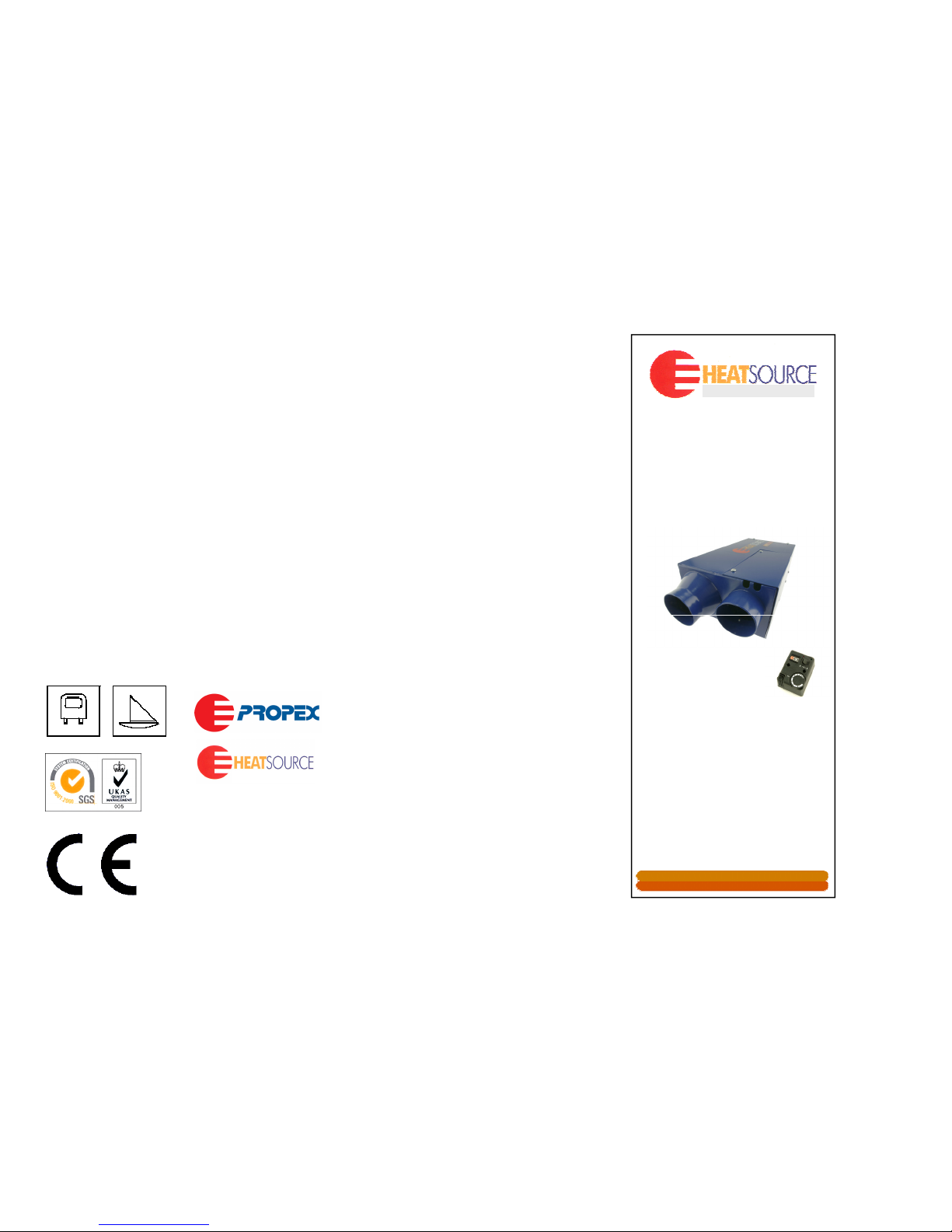
HS2000
Heater
Distributed by; PROPEX
HEATSOURCE LTD
Unit 5, Second Avenue Business Park,
Millbrook, Southampton. SO15 0LP
Tel: 023 8052 8555
Fax: 023 8052 8800
Website: www.propexheatsource.co.uk
Email: [email protected]
Vehicle
Installation
&
Operation Instructions
E N G I N E E R E D F O RE N G I N E E R E D F O R
C O M F O R T & R E L I A B I L I T YC O M F O R T & R E L I A B I L I T Y
180.121
Issue 6F
Page 2

SAFETY WARNINGS & GENERAL INFORMATION
The Heatsource HS2000 is intended for use only as a space heater in
caravans, motor caravans, mobile homes/units and boats (see b below).
Installation and servicing of this appliance must only be carried out by persons
registered with the Gas Safety Register (GB), Corgi (NI), or the relevant national
organisation, in accordance with the relevant regulatory and safety
requirements.
Heater installations must comply with the current British standards for
Motorhomes / Caravans and BS 5482 Part 3 for Boats, and must not be
used incorrectly. Heatsource HS2000 is only suitable for boats when
supplied / fitted with the correct marine installation kit.
This heater is not suitable for installation on the outside of the vehicle.
The heater must not be operated when refueling: the vehicle, towing
vehicle, other appliances or when the vehicle is in a confined space, such
as a garage.
The exhaust gas outlet must not be fitted on the entry door nor in any
position where combustion products may enter the interior.
The heater is designed to operate on Propane gas 37mbar or Butane at 28
or 30mbar (I3+and I 3B/P (30)). The HS2000 may also be used on 30mbar
a)
b)
c)
d)
e)
f)
FAULT FINDING
The Heatsource HS2000 is equipped with an electronic diagnostic system which will detect
fault conditions ranging from poor gas or electricity supply to internal heater malfunctions. In
the event of a failure the yellow light on the thermostat or timer control will flash a certain
amount of times, pause, and repeat until switched off. Count the amount of flashes and refer
to the table below.
Manual Overheat Cut-Out.
The HS2000 incorporates an overheat cut-out which has to be reset manually. If the heater reaches an unusually high tem perature during operation the cut-out
will disengage the gas solenoid valve, cutting off the gas supply to the burner. The operation
of this cut-out could be caused by either a restricted hot air outlet or air inlet, or the heater
being switched off by a battery isolating switch depriving it of its purge cycle. To find the cutout, remove the electronics cover on the heater and look for it positioned above the PCB with
2 yellow wires attached to it. Press the small red button between th e terminals, the fault code
is 7 flashes.
FAULT FINDING TABLE
Number
of
flashes
Fault Remedy
2
Flame
failure
Check gas supply making sure there is gas in the bottle and no
blockage in the gas line. Ensure propane is used at
temperatures below +5°C. Clear lockout as described below.
Low/ high
Minimum operating voltage is 10v and max operating voltage is
15v (for 12v heaters) when measured at the heater. Check
propane but the heat output will be reduced. A 50mbar Propane model is
also available. Under no circumstances should an adjustable regulator be
used.
Do not allow materials to come in to direct contact with the heater. Under
no circumstances must the re-circulation air inlet be covered or obstructed
at any time.
The Heatsource HS2000 heater has a type C53flue, and has been tested
and passed the relevant sections of the following standards:
EN 50081-1:1992, EN 55014-1:1993, EN 60945: 1997, EN 298(NNA):1995,
EN 55014-2:1997, EN 50165:1997, EN 50082-1:1997, BS EN 624:2000,
BS EN 298:1994
A data label is situated adjacent to the gas inlet.
The gas supply line should be checked regularly for damage or leaks and
tested under pressure with a proprietary leak tester. NEVER TEST FOR
GAS LEAKS WITH NAKED FL AME. If a gas leak is detected or smelt,
turn off gas at the bottle immediately and ventilate the area. Contact a
registered installer (see a) above) to rectify the problem.
- 2 -
- 7 -
g)
h)
i)
j)
k)
3
Low/ high
voltage
battery voltage. If above 10v, check connections between
heater and battery. Check alternator or external battery
charging. Clear lockout as described below.
5
Combustion
air fault
Check combustion air flue and exhaust flue for blockages.
Possible blockage in combustion air inlet/outlet duct.
Inspect duct for blockage/damage. Inspect inlet pipe
on the heater (closest to the back) for signs of damage.
7
Overheat
fault
Hot air temperature is too high. Check the air ducts and vents
are not blocked or restricted. We recommend you wait at least 5
to 10 minutes to allow the heater to cool before clearing
lockout as described below. Check ducting for blockages.
6,9,10 Other faults
Attempt to clear lockout as shown below. If this fails, contact
Propex
No
flashing
PCB not
powered up
Check the supply to the heater as above. Otherwise contact
Propex
Gas Lockouts
Gas lockouts must be cleared by moving the left-hand knob from gas on (flame) position
to off position then back to the on position. The complete sequence of switch movements
must be completed within 2.5 seconds for a lockout to be successfully cleared. If there is
air in the gas line, e.g. after a gas bottle change, the space heater may require several
attempts before it lights.
Countries of Destination: GB,IE,FR,IT,ES,BE,PT,DE,NL,DK,SE,FI,CH,LU, NO,GR
IMPORTANT: Do not direct the combustion products outlet terminal (exhaust flue)
towards the combustion air inlet terminal.
Page 3

A 0.75 metre length of 22mm flexible stainless steel tubing with a special
end cap is supplied for ducting the products of combustion away to the
edge of the vehicle. The tubes may not be shortened but can be extended
for certain applications
A “P” clip is provided for fixing the end of the pipe to the underside of the
vehicle with t he end cap slightly protruding under the sill or bumper and
pointing towards the rear of the vehicle.
The maximum overall length of the flue and inlet pipe combined can be up
to 2 metres if required. However, the flue pipe should never be shorter than
the combustion air inlet pipe.
A 0.75m length of combustion air pipe is provided, which is also fitted with
an end cap. This should be attached to the heater with the hose clip
provided and pointed in the same direction as the flue pipe.
Note: The combustion air pipe can be terminated underneath the vehicle
making sure the end of it is at least 0.5 metres away from the end of the
exhaust and that they are not pointing directly at each other. Take care to
ensure that both pipes have a slight downward slope to prevent any
possibility of water traps. Make sure that neither the flue or the combustion
air inlet pipe are terminated in an under-floor box section.
WIRING INSTRUCTIONS
f)
The Heatsource HS2000 heater is supplied with 2 wring looms, a 2 core
(red and black) and a 5 core (red, black, orange, white and green), both are
fitted with terminals and housings to plug into the main PCB positioned
under the removable electronics cover on the heater. The connectors on
the PCB are marked CN24 (power) and CN27 (switches) Grommets are
fitted to the looms which should slide into the slots above the air inlet.
Find a suitable location for the thermostat between waist and shoulder
a)
b)
- 4 -
The heater uses an 8mm (5/16”) gas connection but can be fitted with an
adaptor to take ¼” copper pipe if preferred.
The gas supply should be connected with copper gas pipe with an isolating
valve and all connections made with brass compression fittings, fitted with
copper olives.
Both the air inlet and exhaust hoses MUST be sealed with silicone (tape or
beading) to ensure a gas tight seal and must be inspected annually in
accordance with national regulations.
When the gas line is complete all joints should be tested for leaks using
leak detection solution - NEVER WITH A NAKED FLAME.
Gas pressure should be verified where the gas pipe connects to the heater
using a low pressure gauge or “U” tube, any tests or connections should
only be undertaken by a registered person (see item a) on page 2).
NOTE. Net Heat Input: 2.1kw, average consumption 148 g/h.
- 5 -
GAS CONNECTION
height.Make
sure
thatitis
not
mounted
inanarea
with
poor
air
circulation
or in an area with above average heat, such as above a cooker, refrigerator
or in direct sunlight.
When you have chosen the location, drill a pilot hole in the area you expect
to retrieve the 5 core cable. If the clearance is OK, open the pilot hole out
to 10mm.
Run the 5 core cable fr om the heater to th e thermostat location and remove
approximately 60mm of the outer insulation.
Remove the thermostat knob by gently prizing it off and undo screws “A” to
remove the cover.
Fix the backplate with the PCB to the wall making sure the 5 core cable is
pulled through the hole in the centre.
Connect the cable to the terminal blocks as in the diagram and refit the lid.
Replace the thermostat knob and push the finishing caps into the lid to
cover the screw heads
Run the 2 core cable to a convenient supply (usually at the battery) and
connect using th e fuse h older supplied. Check battery is12v or 24v as
appropriate. Refer to data label for heater voltage. Insert the 5 amp fuse
and test.
c)
d)
e)
f)
g)
h)
i)
a)
b)
c)
d)
e)
Page 4
Switch on
Find a suitable location which allows access to the heater with suitable
room for service and inspection, usually in a bed-box or locker. The
Heatsource HS2000 sh ould be fitted in an area allowing a minimum
distance of 25mm from adjacent walls, ceiling or shelves from the main
body of the heater. Check that there are no chassis members underneath
FITTING THE HEATER
OPERATION
Check the gas supply is turned on and that the battery voltage is correct
(see specifications).
Rotate the thermostat dial fully anti-clockwise and push the 3 position
switch to the left.
Rotate the th ermostat dial until the green light illuminates. After 2 seconds
the heater motor will start and ignition should occur after a 15 second prepurge cycle. When gas is running yellow light is illuminated.
Find the desired temperature setting by adjusting the dial on the the rmostat.
The heater will then cycle on and off to m aintain that temperature.
When the set temperature is reached the green and yellow light will go out
and the heater will start its post purge cycle.
If the 3 position switch is depressed on the right, the green LED will
illuminate and the fan will blow cold air continuously.
Sequence of operation:
a)
b)
c)
d)
e)
f)
g)
a)
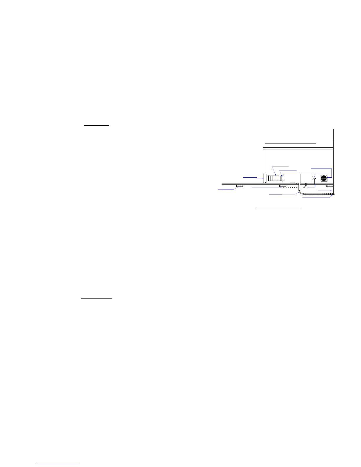
VEHICLE INSTALLATION
Before use: Pay particular attention to the exhaust outlet and combustion air
inlets to check that neither have been blocked or damaged, e.g. in winter,
ensure that any snow or slush is removed.
SOURCE
HEAT
HS2000
Gas Pipe
Recirc Air Intake
Hot Air Ducting
Vent For Air Inlet
Gas Test Point
BEDBOX OR LOCKER
Hot Air Outlet
Vehicle Chassis
Combustion Air Inlet Pipe
Stainless Steel Flue Pipe
Exhaust Pipe Retaining Clip
Sill of Vehicle
Heater motor starts
15 second pre-purge to clear gases from heat exchanger
Gas valve opens
Spark generator operates
Heater lights and runs on reduced motor speed for 30 seconds
Motor speeds up to normal operating speed
Heater switches off when thermostat temperature reached
Post Purge – fan runs on its own for 3 minutes
Temperature drops
Cycle repeated
- 6 -
the location of the exhaust and combustion air spigots.
Using the template provided, drill a 3mm pilot hole through the exhaust and
combustion air spigot centres. Examine underneath the vehicle to check
that there is adequate clearance for a 40mm hole saw. Cut away any carpet
or matting around the exhaust and open out the holes to 40mm. Ensure
that three sides of the underfloor space are kept open and are not
obstructed.
Loosen the 4 x M4 screws on the base of the heater and slot the mounting
brackets into position, then re-tighten the screws. Mount the heater in
position and mark the 4 mounting holes on the floor of the vehicle for
screwing the heater down. Remove the heater an d drill 4 x 3. 5mm holes in
the marked positions, then screw the heater in place with the 3/4 x N0.8 self
tapping screws provided.
Find suitable locations for the hot air outlet and re-circulation air inlet vent
and drill a 5mm pilot hole through each centre. Using a 95mm hole saw,
drill out the holes and fix the vents in position using the black 1/2 x No.8
counter sunk self tapping screws provided.
Fix the 60mm reducer (push fit) into the back of the hot air outlet. Cut the
60mm ducting to length and fix to the heater and the outlet using the 5070mm hose clips provided.
NOTE: There is no reducing spigot provided for the air inlet vent, as it is not
necessary to put ducting on it.
- 3 -
MAINTENANCE
The installation must be inspected and tested annually by a registered person
(see item A on page 2) and any servicing and cleaning identified carried out.
Servicing and removal of the main cover must only be performed by an
approved fitter or the manufacturer.
The heater should not be left for long periods without use. It is advisable to run
the unit for short periods throughout the summer.
The exhaust and inlet pipes should be inspected periodically for damage and
any build-up of dirt around the ends. Clean or replace as necessary.
b)
c)
d)
e)
 Loading...