

Owner’s Manual
with Installation & Troubleshooting Instructions
200,375,575 Series Heat Only Models 575HC and 700HP Series Models
For Heat Siphon® Swimming Pool Heat Pumps
All Z & C Series Heat Siphon Models including
220Volt -1 Ph-60 Hz ONLY: C200HP, C250HP, C375HP, C575HP, Z250HP, Z375HP , Z575HP, Z700HP
220Volt -1 Ph-50 Hz ONLY: C200HP50, C250HP50, C375HP50, C575HP50, Z250HP50, Z375HP50 , Z575HP50
220Volt -3 Ph-50/60 Hz: C250HP3, C375HP3, C575HP3, Z250HP3, Z375HP3 , Z575HP3, Z700HP3
380/460 Volt - 3 Phase - 50/60 Hz - C200HPX, C250HPX, C375HPX, C575HPX, Z250HPX, Z375HPX, Z575HPX, Z700HPX
440 Volt - 3 Phase - 60Hz - C575HP4, Z575HP4, Z575HP4, Z700HP4
Copyright 2019 United States ThermoAmp Inc. ALL RIGHTS RESERVED
Publisher: United States ThermoAmp Inc.
1223 Heat Siphon Lane , Latrobe, Pa. 15650
724-537-3500
i

Weperformtokeepyouwarm
Greetings from the President
of United States ThermoAmp Inc.
MadeinLatrobePasince1983
Thank you for purchasing your Heat Siphon® Swimming Pool Heat Pump.
Since 1983, Heat Siphon® has stood alone as the most innovative, most efficient and most reliable pool or spa
heater made. Over the years our success and innovation has bred a few assemblers and manufacturers who have
made look alike pool heaters and who have adopter many of our features.
But MAKE NO MISTAKE - We have invented, designed and pioneered most of what has become the swimming pool
heat pump of today. Heat Siphon® was the first pool heater to use a titanium heat exchanger, the Copeland Scroll
compressor and vacuum formed PVC cabinets. We are the only pool heater manufacturer using a patent pending
electrically isolated heat exchanger backed by an unconditional lifetime full replacement corrosion warranty. We
have consistently had the highest efficiency ratings in the industry.
Heat Siphon has been made in Latrobe, Pennsylvania since 1983. We are a true MADE IN AMERICA MANUFACTURER. We started here and never left. Today, we believe Manufacturing is coming back to the USA.
We process raw material into finished product to maximize in house manufacturing so we can control the quality
and reliability of our product. We completely fabricate our water side heat exchanger including all brass, teflon,
stainless and titanium fittings and seals inhouse. We vacuum form UV stabilized PVC cabinets from raw material.
We use in-house computer controlled (CNC) equipment including lathe, mill, 5 axis router, tube cutoff and
3 axis tube bender, TIG orbital welding and vacuum forming machines, automated production testing as well as
custom made manufacturing equipment and tooling all to help our production personnel build what we believe
is the best pool heater made.
And if something does go wrong, we spend more per unit than any pool heater manufacturer to ensure your
problems are quickly resolved.
We are constantly looking for ways to improve. You can rest assured that if there is a better way to build it, we
will find it and if there is a better way to serve you we will do it.
And please remember our company motto . . . "WE PERFORM TO KEEP YOU WARM"!!
So, If you have any questions, concerns or suggestions - We would LOVE to hear from you!!
Sincerely,
____________________________________
William P. Bernardi, President, United States ThermoAmp Inc.
ii

Table of Contents
Owners Section ..........................5
1 How Heat Siphon® Works ....................5
2 Heat Siphon® Exterior Parts ...................6
3 Use a Qualified Installer ......................7
4 Plan Your Installation .......................7
4.1 Picking The Proper Size Heat Siphon® ...........7
4.2 Locating Your Heat Siphon® .................7
4.3 Provide Full Flow - No Bypass ...............8
4.4 Provide Proper Clearance & Fresh Air ...........8
5 Pool Heating Considerations ...................9
5.1 Sizing Yo ur Heat Siphon ....................9
5.2 Pool Pump Run Time .....................10
5.3 Filtration Considerations ..................10
6 Owner Troubleshooting .....................11
6.1 Unit Does Nothing ......................11
6.2 Unit Tries to Start then Does Nothing ..........12
6.3 Unit Runs But Doesn’t Heat ................12
6.4 Unit Runs & Heats But Leaks Water ...........13
7 Maintenance & Winterizing ..................13
7.1 Lubrication ............................13
7.2 Cleaning .............................14
7.3 Winterizing ...........................14
Installer Section ......................... 16
1 Receiving Shipment ........................16
1.1 Moving & Handling Precautions .............17
2 Planning Installation .......................17
2.1 Physical Locati on .......................18
2.2 Prohibited Locations .....................18
2.3 Distance From The Pool ...................19
2.4 Distance from The Spa ....................19
2.5 Pool Piping Required. ....................19
2.6 Electrical Power Required. .................20
3 Wiring Heat Siphon® .......................20
3.1 Electrical Hookup on Unit ..................21
3.2 Code Requirements ......................21
3.3 Supply Circuit Wire Size ...................21
3.4 GFCI Breaker Protection ...................22
3.5 Electrical Disconnect Switch ................23
3.6 Electrical Bonding Requi rements .............23
4 Special Installations ........................24
4.1 Indoor Pools ...........................24
4.2 Multiple Units .........................24
4.3 SPA Heating Issues - See APPENDIX D ...........25
4.4 Tools / Materials Required .................26
4.5 Optional Recommended Materials ...........26
4.6 Helpful Hints ..........................26
5 Final Power Line Wiring .....................27
6 Final Plumbing into Pool or Spa ...............27
6.1 In Floor Cleaning Systems ..................28
6.2 Pool Spa Combo Plumbing .................28
1 Pump- Heating Pool or Spa .................30
1 Pump- Spillover Mode ....................31
2 Pump- Heating Pool or Spa On ly .............32
2 Pump- Spillover Mode ....................33
Initial Start-up .......................... 34
1 Initial Performance Checks ...................34
1.1 First Startup of Analog Models ..............34
1.2 First Startup of Digital Models ..............35
1.3 Adjusting the Water Pressure Switch ..........35
1.4 Water Pressure Switch Location: .............36
Digital Player Section .....................37
1 Reading The Player Display ...................37
1.1 The Player Display Info ...................38
1.2 LED STATUS Lights .......................38
2 Changing Pool Temperature ..................39
2.1 Changing Units (°F / °C) ..................39
3 Player Operating Modes .....................39
3.1 POOL Mode ...........................40
3.2 SPA Mode ............................40
3.3 OFF Mode ............................40
3.4 AUTO-PIC Mode ........................40
3.4.1 How AUTO PIC Works .................40
3.4.2 AUTO PIC LED lights and display ..........40
3.5 EC Mode (External Control) ................42
3.6 TEST Mode ............................42
4 Switchi ng Modes .........................42
4.1 Pool/Spa/Auto/Of f ......................42
4.2 Entering EC Mode .......................43
4.2.1 Changing MAX EC set point .............43
4.2.2 Manual OFF in EC Mode ...............43
4.2.3 Exiting EC Mode .....................44
4.3 Switching Modes - For Heat/Cool Units Only ....44
4.4 Locking the Player .......................44
5 Special Settings in TEST mode .................44
6 Commercial Player Spa Modes ................45
6.1 STOP SPA Option ........................45
iii

HEAT SIPHON® Owner/Service Guide
6.2 T-SPA - Timed SPA Mode ..................45
7 Error and Warning Codes ....................46
7.1 Low Refrigerant Pressure (Lo P) .............47
7.2 Low Air Temp. Warning (Lo A) ..............47
7.3 High Refrigerant Pressure (Hi P) .............48
7.4 Low Water Flow (Lo / FLO) .................48
7.5 Water Sensor Open (SH o) .................49
7.6 Water Sensor Short (SH S) .................49
7.7 High Volts (H i / UoLt) ....................49
7.8 Low Volts (Lo / UoLt) .....................49
7.9 Ma in Contactor Short (HS S) ................50
7.10 Main Contactor Open Circuit (HS o) ..........50
7.11 Can’t Heat (CAnt / HEAt) ..................50
7.12 Air Temp Sensor Open (SA o) ..............50
7.13 Air Temp Sensor Short (SA S) ...............50
7.14 No POD (no / Pod) ......................51
7.15 PumpJump Coil Short (PJ S) ...............51
7.16 No Flow w/ Pump Jump(Lo F / Pod) .........51
7.17 Flow w/ Pump Jump (FLO / Pod) ............51
7.18 Pod Coil Open (no / Pod) .................51
7.19 High Air Temperature (Air / Hi) .............52
7.20 Low Air Temperature (COLD / xxF) ..........52
7.21 Reversin g Valve Coil O pen (CH o) ...........52
7.22 Reversing Valve Coil Short (CH S) ...........52
7.23 Easy Pic/Clock No Board (no / EASy) .........52
7.24 Circuit Board Errors .....................52
Analog TimerStat Pro Section ..............53
1.1 Still Keeping it Simple ....................53
1.2 Easy to Upgrade to Digital .................53
1.3 Timerstat Pro Error Codes - Status LED .........53
Appendix A ..........................A-55
Analog Model Wiring D iagrams ...............A-55
TimerStat Pro 220 volt-1 ph-50/60Hz (2 Pole) ...A -55
TimerStat Pro 220 volt-1 ph-50/60Hz (3 Pole) ...A-56
TimerStat Pro 220 volt-3 ph-60Hz ...........A-57
TimerStat Pro 380 volt-3 ph-50Hz ...........A-58
TimerStat Pro 440 volt-3 ph-60Hz ...........A -59
Digital Model Wiring Dia grams ................A-60
Digital 220 volt-1 ph-50/60Hz (2 Pole) ........A-60
Digital 220 volt-1 ph-50/60Hz-(3 Pole) ........A-61
Digital 220 volt-3 ph-60Hz ................A-62
Digital 380 volt-3 ph-50Hz ................A-63
Digital 440 volt-3 ph-60Hz ................A-64
Appendix B ...........................B-65
Specifications by Model .....................B -65
Classic "C" Series (TimerStat Pro Equipped) .....B- 65
Digital "Z" Series (Player Equipped) ...........B -65
Classic "CF" Flow Sensing Series .............B- 66
Digital "ZF" Flow Sensing Series .............B -67
Appendix C ...........................C-68
Accessories Available .......................C- 6 8
1.1 Hardwired Add-Ons ...................C- 68
1.2 Wireless Add-Ons ..................... C- 69
1.3 Other Accessories ..................... C-6 9
Appendix D .......................... D-70
SPA / HOT TUB Heating Issues .................D-70
WARNING! Water Temperature Safety ...........D -70
Thermostat Set Point Depression . . . . . . . . . . . . . . . D -71
Spa Temperature Sensor Calibration .............D-73
Spa Thermostat Set Points above 102°F ..........D -74
USA Warranty Certicate .................. 76
iv

HEAT SIPHON® Owner Section
Evaporator
Fan
Expansion
Valve
Compressor
Heat Siphon
Condenser
1
2
3
4
Electricity
Pool Water
Electrically Isolated
Titanium Fittings
Pure
Titanium Tubing
(Freon Inside)
PVC Shell
ELECTRICAL
GROUND
Owners Section
The Owner Section is written specifically for you, the pool owner. It explains proper operation and maintenance
of your Heat Siphon.
Heat Siphon® Overview
1 How Heat Siphon® Works
Heat Siphon® is a heat pump designed specifically for recreational water heating (pools and spas).
If you have an air conditioner, dehumidifier, water cooler or a refrigerator, you already own a heat pump. All
these appliances use the same dependable technology to move heat from one place to another using electric power
and a sealed refrigerant compression system. Just like a room air conditioner moves 2 to 3 units of heat from your
home for every unit of electricity it consumes, Heat Siphon® uses 1 unit of electric energy to move 4 units of heat
from the air and thus it provides 5 units of heat to your pool.
Referring to the diagram above - A unit of electrical energy (you pay for) goes into the compressor motor (1) .
The compressor turns this into mechanical energy and sucks cool gas from a gas-liquid refrigerant mixture in the
evaporator tubes. As the refrigerant evaporates it absorbs four units of "free" heat from the warmer air that the fan
pulls over the outside of the evaporator tubes.
The compressor squeezes this gas causing its temperature to climb above 200° F and adds the electrical/mechanical energy as another unit of heat. This hot high pressure gas then enters the condenser coil (2) and heats
the colder (80° F) pool water being circulated over the outside of the coils.
As it cools, the refrigerant gas condenses back to a liquid at high pressure then rapidly expands thru a valve (3)
back to the lower evaporating pressure.
This rapid pressure drop super cools the liquid refrigerant as it enters the evaporator (4) where it repeats the
Owner - 5

HEAT SIPHON® Owner Section
cycle. SO YOU PAY FOR ONE UNIT OF HEAT AND GET FOUR FREE!! . . . And with the NEW models you get FIVE
to SIX units FREE!!
2 Heat Siphon® Exterior Parts
The following Illustration identifies the basic exterior components and parts of your Heat Siphon.
DIGITAL MODELS
Player Controller
ANALOG MODELS
TimerStat Knob
ELECTRICAL
CONTROL BOX
JUNCTION BOX
Power In (Wire Nuts)
NAMEPLATE
CONDENSATION DRAIN
Barb Fitting for ¾” Vinyl Tubing
SVC PORT DOOR
Hi/Lo Pressure Refrigerant
Std. ¼” MFL Fittings
WATER OUTLET
1½” SCH 40 Slip Inside and
2” SCH 40 MPT Outside
WATER INLET from Pump
to Pool
1½” SCH 40 Slip Inside and
2” SCH 40 MPT Outside
COOL AIR
OUT
STAINLESS STEEL
FASTENERS
BACK PANEL
BONDING LUG
BASE PAN
FAN GUARD
VENTURI TOP
EVAPORATOR
WARM AIR
IN
ELECTRICAL
CONDUIT ¾” NPT
HAND HOLE
GRIPS
Heat Siphon® Exterior Parts
Don’t Void Your Warranty!
This section contains all the information you will need to ensure that your Heat Siphon® has been properly
installed. Read this section before allowing a new dealer to install your unit. If your installer is not an Authorized
Heat Siphon® Dealer make sure they are licensed by your county, trained and have experience installing pool
plumbing, wiring and pool heating equipment.
Owner - 6

HEAT SIPHON® Owner Section
3 Use a Qualied Installer
Although your Heat Siphon® Swimming Pool Heat Pump has the strongest manufacturer’s warranty of any
pool heater made, there are things your installer could do incorrectly to cause you problems and expenses which
will not be covered by the factory under this warranty. (See the Appendix for your Heat Siphon® Factory Warranty.)
As the owner you should be aware that your Heat Siphon installer is totally responsible for performing the following
key installation steps.
4 Plan Your Installation
You and your Dealer / Installer must be responsible for the following
• Picking the Proper Size Heat Siphon® for Your Pool
• Selecting the Proper Location
• Providing Proper Air / Service Clearance Around the Unit
• Correctly Plumbing for FULL PUMP FLOW - NO BYPASS
NOTE: FAILURE TO DO SO MAY VOID YOUR WARRANTY!!
4.1 Picking The Proper Size Heat Siphon®
Your dealer should provide you with a Heat Siphon® that is large enough to heat your pool under normal
conditions within 8-12 hours of run time each day. Under-sizing will result in long run times and possibly a pool
which isn’t always as warm as you want it to be.
Normally a Z375HP Heat Siphon® will be more than adequate to heat most in ground residential pools to
over 82° F. Most established Heat Siphon® dealers, can tell from experience what size will work on your pool. If
there is a doubt about sizing, or if you have a larger pool , abnormal wind or shade or you wish to keep your pool
uncovered 24 hours a day, then make sure your dealer has taken this into account.
TIP: Anyone can request our free factory computer pool heating analysis. It very accurately determines the
proper size (and number) of Heat Siphon(s) for your pool as well as the expected heating cost. You specify your
location (for climate data), the pool temperature you desire, the months it will be open, the hours per day covered,
the wind condition, the pool pump hours and your local fuel costs. It will be emailed or FAXED back SAME DAY.
This four page printout also provides graphics showing pay back period, monthly operating cost and much
more and it’s FREE. (See the sampleon our website www.HEATSIPHON.com)
4.2 Locating Your Heat Siphon®
As long as you provide plenty of fresh air and give it adequate clearance space all around, Heat Siphon can be
installed virtually anywhere outdoors. Unlike gas heaters whose pilot lights can be blown out, Wind has no effect on
Heat Siphon® other than possibly helping the fan and increasing the heat output. Do not place your Heat Siphon®
under a deck, in a pump house or under a roof overhang. These locations do not provide "fresh air", instead they
cause air recirculation, reduce efficiency and compressor life and void your warranty.
It’s solid PVC cabinet , stainless steel hardware , vinyl coated fan guard and evaporator screen will remain unaffected by the elements. The plastic basepan has a drain fitting to carry rain water as well as condensation away
Owner - 7

HEAT SIPHON® Owner Section
from the unit. A 3/4” diameter clear vinyl tube will slip right over this barb type fitting to plumb the water away.
As far as direct sunlight is concerned, Heat Siphon’s UV stabilized, flame retardant PVC plastic cabinet material
is far superior to any type of galvanized or painted sheet metal cabinet. It won’t rust, fade, chip or peel.
If the air temperature drops below about 42°F while the Heat Siphon® is running then any water in the air
will begin to freeze and form frost or ice on Heat Siphon’s large horseshoe shaped evaporator fins. This is because
Heat Siphon®’s refrigerant must be colder than the air to remove heat from it and dips below freezing at about
this air temperature.
Although this will cause no structural damage, it may take as much as 24 hours to melt and it will drastically
reduce efficiency. Over a long period this can reduce the life of your compressor.
To prevent this icing your Heat Siphon® is equipped with a freeze protection switch that automatically turns
the Heat Siphon® off if the refrigerant temperatures goes below freezing. It will automatically restart and continue
heating the pool as soon as there is no icing danger at about 48°F.
4.3 Provide Full Flow - No Bypass
WARNING
Any damage due to incorrectly plumbing your Heat Siphon installation is
not covered by the warranty.
DO NOT INSTALL A BYPASS
Heat Siphon® requires FULL PUMP FLOW with at least 25 to 30 GPM.
Heat Siphon®’s full flow heat exchanger will accept up to 80 GPM with
very minimal pressure drop. Installing a bypass can reduce flow below the
minimum required and overheat the condenser causing the unit to cycle
on and off every 5 minutes. If allowed to continue, cycling can shorten the
unit’s life and damage the compressor which is not covered by the warranty.
DO NOT INSTALL SHUTOFF VALVES DOWNSTREAM
Plumbing shut off valves downstream of the Heat Siphon® in a way that
results in the pool pump pressurizing the Heat Siphon® with no water flow
can also cause short cycling damage.
4.4 Provide Proper Clearance & Fresh Air
Heat Siphon® can not be installed where the cooler exhaust air (flowing straight up out of the unit) is recirculated
back into the intake (sides) of the unit. This will reduce efficiency as well as heat output.
Owner - 8

HEAT SIPHON® Owner Section
HEAT
SIPHON
Heat Siphon Installation Space Required
for Air Flow & Service Access ALLOW 12 to 24 inches AROUND ALL SIDES
12”Min
12”Min
24-36" Service Access
Colder Air Out Top
Warmer Air In Sides
PREVENT
Air
Recirculation
At least two feet of clearance must be provided around the unit as well as unrestricted air flow overhead.
Installing a Heat Siphon® under a deck or in a pool equipment shed or enclosed area or too close to shrubs
will result in air recirculation, poor performance and short cycling which can shorten the unit’s life and damage
the compressor AND WILL VOID THE WARRANTY.
5 Pool Heating Considerations
5.1 Sizing Your Heat Siphon
Heat Siphon® is equipped with a flow sensing switch which turns it on and off automatically when the pool
pump is turned on or off. However, you must still run the pool pump long enough each day to allow Heat Siphon®
to maintain the pool water temperature.
Make sure that your dealer provides you with a Heat Siphon® that is large
morning to restore the pool to temperature. If your pool pump is sized to run 8 hours per day for filtration, during
a cold spell or other high heat loss period such as when the pool is uncovered for an extended windy period, the
Heat Siphon® may require longer pump operation to maintain temperature. This will not require excessive pool
pump operation and will ensure a reserve heat output capacity to cover any temporary high heat loss conditions.
pool heating and filtration. If in doubt call the factory and we will be glad to furnish a free computerized pool
or spa heat loss analysis that will show recommended pump operating times and operating costs for each month
enough to heat your pool under normal conditions with 8-12 hours of
pump operation each day
If the pool pump is off during the night and the pool loses heat then it may take several hours or more in the
A properly sized Heat Siphon® and a smaller pool pump are the most cost effective combination to ensure proper
Owner - 9

HEAT SIPHON® Owner Section
Including extra pool pump electric costs if you do choose to oversize.
Tip: Visit our website WWW.HEATSIPHON.COM for a sample print out or DOWNLOAD our iPhone/iPad Pool
Designer app MYPOOL at the App Store.
5.2 Pool Pump Run Time
Just like other pool heaters, Heat Siphon® can add heat to the pool only when the filter pump is running. So
the question is how many hours a day do you run your pool pump- 24, 16, 12 or 8 hours per day?
NOTE: In ANY given pool or spa piping system, if you DOUBLE the flow
rate, you QUADRUPLE the WATTS needed to pump water thru it. Put
another way - PUMPING 1000 GALLONS IN ONE HOUR through your
pool filter TAKES 4 TIME THE WATTS as pumping 1000 GALLONS IN
TWO HOURS!!
How long to run your pool pump each day?
1. You must run the pool pump long enough to FILTER OUT ANY DIRT AND DEBRIS.
2. You must run the pool pump long enough to allow the HEATER to REPLACE THE DAILY HEAT LOSS.
3. If you use a feeder, chlorinator, ionizer etc., the manufacturer’s recommendations must be followed.
Picking a pump too small OR running a variable speed pump on low speed will result in inadequate filtration
time. Using a pump that is too large OR running a variable speed pump on high speed will increase both system
back pressure and electric cost.
The most efficient and lowest cost pool pump system is one where the pool pump has a flow rate just large
enough to pump (turn over) your entire pool volume through your filter in 8 to 12 hours. This means running the
pump continuously to get the recommended 2 to 3 turnovers per day for proper filtration while pumping against
the lowest back pressure possible.
5.3 Filtration Considerations
The number of bathers, amount of chemicals added as well as the temperature and weather all vary the actual
filtration required to maintain a clear clean pool.
In most commercial pools, state laws usually require 3 turnovers per day with the pump running 24 hours per
day (one turnover every 8 hours). Thus a 80,000 gallon pool would need a pump flow rate of 10,000 gallons per
hour or 167 gallons per minute (GPM) to pump the entire volume through the filter in 8 hours. 60 GPM equals
1 Gallon per Hour (GPH).
Pool Turnover Time in Hours = Pool Gallons/ Pump GPH
On residential pools 1.5 to 2 turnovers per day is usually considered the minimum. The size (horsepower) of
your pool pump will determine the flow rate in your pool filter system and thus how many turnovers per day can
be achieved.
Bigger pumps are not necessarily better. Some dealers put in a smaller pool pump sized to run 24 hours a day
because the operating cost is much less per day than running a larger pump for 8-10 hours to get the same number
Owner - 10

HEAT SIPHON® Owner Section
of turnovers. Back pressure increases as the square of the flow rate. Thus, if you cut the flow rate in half in a given
pool piping system, you decrease the back pressure that must be overcome to pump the pool water by 75%. In addition
they claim 24 hour run time saves chemical costs by eliminating shock treatments and by keeping turbidity and
suspended solids to an absolute minimum.
On the other hand are dealers who advocate using large 1. 5 or 2 horsepower filter pumps which turn over
the entire pool volume in 4 to 6 hours and thus they claim need only be run 8-12 hours daily to achieve effective
filtration. If you have different electric rates for day versus night usage, running your pool pump for a shorter time
during “off peak” rates may actually save pump costs overall even though you use more electricity. Ask your dealer
if in doubt or call your electric utility.
The pump flow rate requirements are also affected by the size and type of filter you use. Cartridge filters usually
require 1 GPM (gallons per minute) per square foot while diatomaceous earth may require 2 GPM per square foot
and sand 3 GPM / sq ft. or more. Thus a lower flow rate pump which runs longer can use a smaller but not undersized filter as long as it will not load up too quickly. If a large filter is used with the smaller pump, back pressure
will also be reduced significantly thus further reducing pump electric costs.
In conclusion, in most cases using a longer run time with a smaller pump and a properly sized or even oversized
filter clearly provides the best results from an economic as well as a filtration standpoint.
6 Owner Troubleshooting
The purpose of this section of the manual is to provide some GUIDANCE FOR HEAT SIPHON® OWNERS with
little or no technical background who have a problem with their Heat Siphon®.
If our guidance here doesn’t solve the problem CALL YOUR INSTALLER and refer him to the Installer Section of
this manual. He will contact the factory service center for additional service if required.
When you apply power to your Heat Siphon® through the disconnect and circuit breaker, usually one of four
things will happen
• IT DOES NOTHING
• IT TRIES TO START THEN SHUTS OFF
• IT STARTS & RUNS but doesn’t heat
• IT RUNS & HEATS & sometimes leaks water
In any case you are probably reading this because your pool is not
heating to the desired temperature, so follow the appropriate steps
below BEFORE CALLING YOUR DEALER:
6.1 Unit Does Nothing
Heat Siphon Shuts Down Below 42°F
to Prevent Evaporator Icing and
Automatically Restarts at 48°F
42°F
Here is a step by step troubleshooting procedure if your
unit does not start
1. Is power on?
2. Thermostat set too low? ( turn fully clockwise-unit should come on)
3. Pool pump on and valves properly set?
4. Water flow confirmed from pool through heater and back to pool?
Owner - 11

HEAT SIPHON® Owner Section
5. Air too cold? - Air temperature below approx. 42°F will shut unit off automatically to prevent icing. (Wait for
air temperature to reach 45° F to 48° F - unit should automatically reset and turn itself on)
6. Time delay activated by brief power interruption? (Wait 5 minutes - unit should restart)
7. Is breaker tripped? You may have a bad breaker or faulty wiring, loose wires or poor connection in the junction
box . Have your installer check the wiring and breaker.
NOTE: Some brands of GFI type breakers are extremely sensitive and
are susceptible to false tripping. Have your installer check all wiring
between the unit and the breaker and make sure the breaker is wired
right . (see installer section)
8. Call your dealer. - His first step should be to check & adjust the water flow switch
6.2 Unit Tries to Start then Does Nothing
1. Has the Time delay been activated by brief power on/off? (Wait 5 minutes - unit should restart)
NOTE. The combination of a cold pool (below about 50°F) and a low air temperature (below
about 45°F) MAY cause temporary on off cycling of the Heat Siphon. A pool cover and /or 50°F air
temperature will eliminate this cycling and allow normal heating operation to resume.
2. Is the air below 45°F to 48°F and the pool water cold? (Wait for air temperature and/or pool to reach 50°F
- unit should restart automatically and resume normal heating)
3. Is the pool filter clean and pool water flow stable? A clogged filter or air leak in the pool pump return line
can cause erratic water flow and air in the lines which in turn can cause Heat Siphon® to cycle- restore
the correct water flow.
4. Is the fan running when the unit is running? - (if not call dealer)
6.3 Unit Runs But Doesn’t Heat
Check these before calling your dealer:
1. Air leaving colder? If not call dealer
NOTE: If Heat Siphon®’s air outlet is noticeably (5 to 10°F) cooler than the inlet air, then the
unit is providing heat to pool. The unit may not have been running long enough to heat the pool
(see next step), or the unit may be undersized. (See proper sizing section above)
2. Pool pump running long enough each day? Normally 12-14 hours/day is sufficient if Heat Siphon ® is
sized properly (let pool pump run continuously for 24 hours to find time required-if not heating call dealer)
3. Is there abnormally high heat loss? No cover on extremely windy day? (Cover pool and run pool pump 24
hours. If still not heating call dealer)
6.4 Unit Runs & Heats But Leaks Water
Water leaking from INSIDE your Heat Siphon is due to one of two conditions
• NORMAL CONDENSATION as it cools off warm humid air
Owner - 12

HEAT SIPHON® Owner Section
• WATER LEAK in the Heat Exchanger Housing or Internal Hose or Piping.
The most common cause of a water leak is CONDENSATION. The second is a CRACKED HEAT EXCHANGER
CAP DUE TO FREEZING. If you have not properly winterized (See next section) this will not be covered under your
warranty. Before calling your dealer, here are some tests you should perform:
1. TURN OFF YOUR HEAT SIPHON, KEEP YOUR POOL PUMP ON and wait until basepan empties. If the Water
Leak Stops IT IS NORMAL CONDENSATION
2. If the Basepan does not empty BUT THE leaking stops it's still condensation but your drain is blocked so
unclog the barb drain fitting and/or replace the vinyl drain tubing.
3. TEST THE LEAKING WATER for Chlorine - If it tests NEGATIVE it's Condensation.
4. If the water has chlorine and the leak continues, call your dealer
7 Maintenance & Winterizing
As well as being virtually corrosion-free, your Heat Siphon® has been designed and built using strictly high
quality, proven reliable components. As a result, you can expect your Heat Siphon® to outlive other heaters and
to require only minimal maintenance over its lifetime. No regular scheduled maintenance is required and only
minimal cleaning and minor lubrication as noted below
7.1 Lubrication
Your Heat Siphon® has only two rotating parts subject to wear and thus requiring lubrication: the compressor
and the fan motor.
Since the refrigeration system compressor is hermetically sealed which eliminates all air and water vapor
contamination, it requires no lubrication or maintenance. The refrigerant inside is extremely stable, has a special
lubricating oil added which lubricates the compressor bearing. The oil and refrigerant are so stable that under
normal conditions they will easily last more than 30 years without breaking down.
The fan motor which is totally enclosed type motor (sealed from rain and dirt) is equipped with a rain slinger
on its shaft to prevent rain water from washing the lubrication out of its sleeve bearings. This should also require
no lubrication for years, however, after several years of service in a hotter climate or if the motor has set idle in a
hot dry environment for many months, the lubrication may begin to dry out and may cause the fan motor bearing
to make noise. If left uncorrected this will eventually slow down and freeze up the fan motor causing short cycling
and may burn it out.
WARNING: Before removing the fan guard , TURN OFF ALL POWER
TO THE UNIT. ACCIDENTAL STARTING OF THE FAN MOTOR WHILE THE
GUARD IS OFF CAN RESULT IN SEVERE INJURY.
You can re-lubricate the bearings using the oil fittings on the side of the fan motor. Remove the two plastic seal
plugs (one at the top and bottom of the motor housing) and squirt in light machine oil.
Owner - 13

HEAT SIPHON® Owner Section
7.2 Cleaning
WARNING: Before cleaning TURN OFF ALL POWER TO THE UNIT. Although each unit is production tested for any ground faults and the
electrical supply hookup is in a gasketed rain tight housing, a faulty
eld electrical hookup or hidden damage to the unit CAN PRODUCE
A FATAL SHOCK HAZARD. Don’t take a chance- DISCONNECT AND
LOCKOUT THE BREAKER BEFORE CLEANING
CAUTION - DO NOT SPRAY WATER DIRECTLY INTO THE HEAT SIPHON
WITH A HOSE OR OTHER HIGH PRESSURE WATER. Although the Heat
Siphon® Is Rain tight it is NOT WATERPROOF and high pressure water
can be directed in a manner that could cause shorting and even
ELECTRIC SHOCK HAZARD.
Heat Siphon’s solid PVC cabinet may be cleaned using any of the automotive vinyl cleaners, or soap and water.
An abrasive cleaner or bathtub porcelain cleanser will remove most stubborn stains. Dirt and leaves should be swept
from the finned horse shoe shaped evaporator if build up occurs. Spraying water is not necessary to clean Heat
Siphon® and normal dirt accumulation will not have any effect on the unit’s performance.
7.3 Winterizing
Warning: If pool or spa water is allowed to freeze in the heat exchanger, it will expand and may crack the heat exchanger housing
requiring heat exchanger replacement which is not covered by the
warranty.
Your Heat Siphon can stand the coldest of winter weather with no problems. The only precaution necessary is to
make sure that the heat exchanger is drained of all pool water. If in doubt add antifreeze to the outlet (top) until
it comes out of the inlet (bottom) of the unit.
In freezing weather the plastic cabinet material does become brittle and should be protected from any impact
but can withstand normal moving and handling.
NOTE: It is totally unnecessary that your Heat Siphon be moved from its
installed location for the winter, and in fact it is recommended that you
leave it intact to avoid damage during moving.
Owner - 14

HEAT SIPHON® Installer Section
Installer Section
This Section of the manual applies to the installer.
1 Receiving Shipment
NOTICE: ALL Shipments by the factory are made F.O.B.. Latrobe, PA. As
such, the buyer (dealer) takes possession of the Heat Siphon® the minute
it leaves the factory loading dock.
United States ThermoAmp, Inc. is NOT responsible for any shipping
damage occurring in transit. THE FREIGHT HAULER IS RESPONSIBLE FOR ALL FREIGHT DAMAGE AND ALL DAMAGE CLAIMS MUST
BE SETTLED DIRECTLY WITH THE FREIGHT HAULER. The factory will
assist you in settling claims wherever possible but YOU MUST DEAL
DIRECTLY WITH THE SHIPPER TO RESOLVE ALL FREIGHT DAMAGE.
IMPORTANT.- IF YOU RECEIVE A DAMAGED HEAT SIPHON® NOTIFY
THE CARRIER IMMEDIATELY (THAT MEANS THE CARRIER’S OFFICE,
NOT THE DRIVER)
CAUTION: A unit which has been dropped will have internal damage
which is not apparent from the outside of the carton. If in doubt
unpack the unit in presence of the shipper at the time of delivery.
Puncture marks and oil stains on the box are indicative of a ruptured
and leaking sealed refrigeration system. AND SHIPMENT SHOULD BE
REFUSED.
Heat Siphon® is designed and packaged to ensure safe arrival even with individual shipments, however, if Heat
Siphon® is tailgated or dropped, the damage may not be visible from outside the box and if you accept shipment
from the trucking company, any subsequent claims of concealed damage will be refused by the freight hauler.
Although unattractive, minor dents in the aluminum evaporator fins won’t adversely affect Heat Siphon®
performance, we suggest that you make note of ANY damages on the Bill of Lading BEFORE signing for receipt.
Damaged fins can be “combed” straight, if not severely smashed, with a “fin comb” commonly carried by most
refrigeration repairmen. Black acrylic enamel spray paint can also be used to repair any cosmetic damage.
1.1 Moving & Handling Precautions
If only a few simple handling rules are followed, Heat Siphon® can be moved virtually anywhere with no problems:
1. DO NOT DROP OR TAILGATE THE HEAT SIPHON .
2. DO NOT LAY THE UNIT ON ITS SIDE OR UPSIDE DOWN.
Installer - 15

HEAT SIPHON® Installer Section
3. DO NO LIFT THE HEAT SIPHON® BY ITS TOP / VENTURI - USE HAND HOLES IN BASE.
Use a fork truck, roller conveyor or an inclined plane to unload the Heat Siphon® carton. Although the special
PVC plastic used in the HEAT SIPHON® cabinet is extremely tough and more than adequate for shipment even in
cold weather, it will probably break or crack if dropped from a truck tailgate.
Usually damage will be in one of three places:
1. Where the 25 pound control panel attaches to the base pan;
2. Where the 20 pound fan motor attaches to the top;
3. Where the 75 to 120 pound compressor fastens to the base pan.
Cracked plastic cabinet parts may or may not need to be replaced but can be expensive to replace if all the
components need to be removed and remounted on a new cabinet part.
Other freight damage - bending of the fan motor mounting bracket that causes the fan blade to rub or rupturing
of a copper refrigerant tube. Usually this can be repaired by a local refrigeration service center with minimal difficulty.
If tilted too far from the vertical position, the weight of the compressor can bend or break tubing or even break
or crack the plastic base pan at the compressor mount.
The top venturi/fan assembly is fastened to the unit using three stainless steel screws which are anchored to sheet
metal flanges. This is more than adequate for ensuring a firm vibration-free assembly to the Heat Siphon® body,
but these mounting screws are not designed to support the entire weight of the unit. Once out of the box, the Heat
Siphon® should be lifted by the base pan only. Hand holes have been molded into the basepan for easier handling.
2 Planning Installation
IMPORTANT - READ THIS ENTIRE SECTION COMPLETELY THRU BEFORE
YOU BEGIN TO INSTALL HEAT SIPHON®
The efficiency of your Heat Siphon® is dependent on its location. Picking the wrong place will not only reduce
the efficiency by causing the cooler air coming out of the top to recirculate back into the air inlet, it may void your
warranty. Please read through this section before you decide where to place your Heat Siphon®
Installer - 16

HEAT SIPHON® Installer Section
HEAT
SIPHON
Heat Siphon Installation Space Required
for Air Flow & Service Access ALLOW 12 to 24 inches AROUND ALL SIDES
12”Min
12”Min
24-36" Service Access
Colder Air Out Top
Warmer Air In Sides
PREVENT
Air
Recirculation
2.1 Physical Location
Normally, the pool piping layout and the electrical supply will dictate the general location of the Heat Siphon®.
In addition, the following guideline should be adhered to when picking the location:
1. Allow 24 to 36 inches of open area all around the Heat Siphon® for good air circulation and service access.
Avoid any overhangs or structures which could cause exhaust air to recirculate from the top of the unit back
into the sides.
2. Ensure the Heat Siphon® will be level when in place to aid in condensation and rain water drainage. Sand
or a cement slab will provide and inexpensive attractive easy to level mounting base with good drainage.
3. Heat Siphon’s noise dampened plastic base pan ensures extremely quiet operation. To further minimize
noise, point the flat side of the unit with Heat Siphon® trademark toward areas people will frequent. The
plastic front panel reduces the already low operating sound level even further in that direction by absorbing
compressor noise which the evaporator side does less effectively.
2.2 Prohibited Locations
DO NOT locate your Heat Siphon in any of the following
places, as the air will be recirculated back to the inlet
and cooled down cycling repeatedly until the efficiency is
degraded and the compressor is overworked. Location in
any of these places will void your warranty:
1. Under a roof overhang
2. Under a deck
3. In a Pool Pump house
2.3 Distance From The Pool
Normally, the pool pump and Heat Siphon® are installed close together and within 25 feet of the pool. The
Installer - 17

HEAT SIPHON® Installer Section
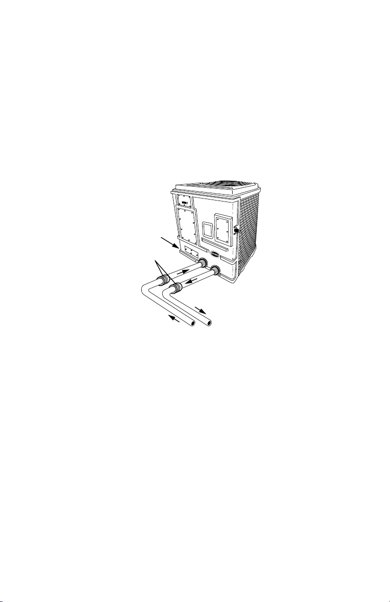
Heat Siphon® Plumbing Installation
Plumb Schedule 40 PVC Pipe 1½” or 2” Diameter Directly into and out of Unit
FULL FLOW - NO BYPASS!!
Pipe Couplers
for Winterization
& Service Bypass
Condensate Drain
in Basepan Hand Hole
Barb Fitting accepts
¾” Vinyl Tubing
FROM PUMP
TO POOL
MINIMUM of 12” of Straight Pipe
between unit to couplers
for panel removal / service
For C & Z Series
200HP / 250HP,
375HP / 575HP Models
longer the distance from the pool, the more heat loss from the piping. Since most of the time the piping is buried,
the heat loss is minimal for runs of up to 50 feet (50 feet to and from the pump = 100 feet total) unless the ground
is wet or the water table is high. A very rough estimate of heat loss per 100 feet of piping is 2500 BTU/Hr. for every
10°F difference in temperature between the pool water and the ground surrounding the pipe, which translates to
about a 3% to 5% increase in run time.
2.4 Distance from The Spa
CAUTION: Special consideration required using any heater with a spa or
hot tub. SEE APPENDIX D
2.5 Pool Piping Required.
IMPORTANT: Allow At Least 12 Inches Of Straight Pipe Between The
Heat Exchanger And Any Coupling Unions Or Elbows To Allow Backpanel
Removal For Servicing .
CAUTION: DO NOT USE ANY BYPASS PIPING. Heat Siphon® Requires
Full Flow From 25 T0 80 GPM. Installing A Bypass May Cause Short Cycling Damage and Will Void Your Warranty.
The Dual-Fitting water ports allow you to glue either 1.5 inch or 2 inch (with a standard 2” PVC coupling)
schedule 40 PVC pipe directly into the heat exchanger. No metal heat sink piping is required. The following graphic
applies to all C & Z 200, 250,375 & 575 series heating only and cooling only models:
Heat Siphon’s exclusive FULL FLOW Titanium heat exchanger has a minimal pressure drop and requires NO
SPECIAL PLUMBING arrangement. It should be considered as just another length of PVC pipe in your pool filtration
system.
Installer - 18
HEAT SIPHON® Installer Section
LOCATION: Connect Heat Siphon® in the pool pump discharge (return) line DOWNSTREAM of all lters and pool pumps,
and UPSTREAM of any electronic chlorinators or chemical pumps.
SIZE: All Heat Siphon®’s have 1.5 “ x 2” ttings for connection to the pool or spa ltration piping which will accept 1.5”
schedule 40 PVC pipe directly or 2” SCH 40 PVC pipe with a 2” PVC coupling. The in-line water pressure drop produced
by Heat Siphon is less than 1.5 psi at 30 GPM.
The following graphic applies to all 575 series Heat/Cool models and all 700 series Models
Heat Siphon® Plumbing Installation
Plumb Schedule 40 PVC Pipe 1½” or 2” Diameter Directly into and out of Unit
For Models
Z700HP/Z575HC
Only
Condensate Drain
in Basepan Hand Hole
Barb Fitting accepts
¾” Vinyl Tubing
Pipe Couplers
for Winterization
& Service Bypass
FULL FLOW - NO BYPASS!!
FROM PUMP
TO POOL
Both Water Fittings:
1½” SCH 40 Slip Inside and
2” SCH 40 MPT Outside
2.6 Electrical Power Required.
WARNING: DO NOT ATTEMPT TO COMPLETE ANY ELECTRICAL INSTALLATION OR SUPPLY CIRCUIT WIRING UNLESS YOU ARE QUALIFIED AND EXPERIENCED IN THE FIELD. Heat Siphon® Requires High
Voltage Power Wiring Which Should Be Installed In Accordance With
All Electrical Codes By A Licensed Electrician With Proper Training.
3 Wiring Heat Siphon®
Connect the proper size wire (including grounding) by electrical conduit,
UF cable or other suitable means (as permitted by local electrical codes) to
a dedicated AC power supply branch circuit equipped with the proper circuit
breaker, disconnect or time delay fuse protection.
3.1 Electrical Hookup on Unit
Heat Siphon® has a separate molded-in junction box on the right side of
the back panel with a standard electrical conduit nipple already in place. Just
Installer - 19

HEAT SIPHON® Installer Section
2000364
US
remove four screws and the small cover, feed your supply lines in through the conduit nipple and wire-nut the electric
supply wires to the three pigtails already in the junction box. (Four or five wires if three phase).
No other pool heater is as easy to wire.
3.2 Code Requirements
The following are National Electrical Code (Article 339-3 and 680-10) requirements regarding burial of the
electric supply wires, and are provided here FOR GUIDANCE ONLY
NOTE: LOCAL CODES SUPERCEDE AND MAY VARY FROM THESE REQUIREMENTS
1. All supply cable should be at least 5 feet horizontally from the pool wall unless it is in a corrosion resistant
metallic, or nonmetallic raceway system and must be buried at least the following minimum depth:
Wiring System ...........................Min. Burial Depth
Direct Burial Cable ............................24 inches
Rigid Nonmetallic Conduit 18 inches (approved for direct burial w/o concrete encasement)
Rigid Metal Conduit........................... 6 inches
Other Approved Raceways .....................18 inches
2. UF cable (approved for direct burial ) is permitted for supply runs from the circuit breaker to the Heat Siphon®.
3. UF cable must be protected from damage where it is exposed (not buried) between the ground and the breaker
box or Heat Siphon® junction box using suitable means.
4. Use copper conductors (wire) only. Aluminum is unsuitable for pool equipment service.
5. Circuit Breaker Size
Warning: Heat Siphon® Requires a DEDICATED BREAKER with NO
other load on the same breaker (such as a pool pump)
The supply circuit breaker or fuse should be AT LEAST the AMPERAGE rating of the HEAT SIPHON® MCA
(minimum circuit ampacity) BUT NOT EXCEED the Maximum Circuit Breaker Size on the NAMEPLATE.
3.3 Supply Circuit Wire Size
Caution - A LICENSED ELECTRICIAN must size and
install your wiring BASED ON THE NAMEPLATE
MCA and in accordance with the NEC.
The following table suggests supply circuit wire size for type UF or
TW conductors assuming a maximum 3 volt line loss is desired for
the basic Heat Siphon® models noted.
The wire sizes are SUGGESTED ONLY based on the National Electrical Code Standards UNDER NORMAL CONDITIONS ONLY and are NOT
intended to supersede local codes or other restrictions that may apply.
All local electrical and building codes as well as the National Electrical
Code (Articles 300 & 310) should be consulted for additional guidance.
Installer - 20
RECOMMENDED/ MAXIMUM
CIRCUIT BREAKER SIZE
SIZE WIRE USING MCA:
MIN. CIRCUIT AMPACITY
MADE IN USA
HEAT SIPHON
MODEL: C250HP
POWER REQ'D: 208-230 1Ø 60Hz
MAX. CIRCUIT BREAKER: 30 AMPS
MCA: 25.4 AMPS
COMPRESSOR: 16.7 RLA 79 LRA
FAN MOTOR: 2.1 RLA .39 HP
FACTORY CHARGED: 3.35 lbs R410A
DESIGN PRESS : 475 PSIG (HIGH AND LOW SIDE)
BTU OUTPUT: 52,400 BTUH @ 80°F H2O/ 80°F AIR
NOT INTENDED FOR 50 Hz Operation
CONFORMS TO UL STD 1995
®
CERTIFIED TO CAN/CSA
L
I
S
D
E
T
STD C22.2 NO. 236
OUTDOOR USE
C
SAMPLE NAMEPLATE
®
SERIAL NO.

HEAT SIPHON® Installer Section
SUGGESTED WIRE SIZES (buried / in air) For Length of Run
Model (Volts/Hz/Phase) .........................50 ft. ............75 ft. ........100 f t.
250 HP (208-230v /60/1) .....................#14 / #14 ........#12 / #12 .... #10 / #10
375 HP (208-230 v/60/1) .....................#12 / #10 ........#10 / #10 ..... #8 / #8
575 HP (208-230v/60/1)..................... #8 / #6 ** .........#8/#6 .......#6 / #6
700 HP (208-230v/60/1)..................... #8 / #6 ** .........#8/#6 .......#6 / #6
375 HPX(44OV/50-60/3)......................#14 / #14 ........#14 / #14 .... #14 / #14
**NOTE: if THWN or TWN conductors are used in conduit and length of run is 50 feet or less, #10 AWG size is suggested if buried and
#8 is suggested if conduit is in free air. If your model is not listed see nameplate MCA and consult an electrician.
3.4 GFCI Breaker Protection
Where possible Ground Fault Circuit Interruption (GFCI) circuit breakers are strongly recommended at the main
power supply for electrical equipment in the pool system. This is one low cost insurance policy which virtually
eliminates shock hazard as well as equipment damage due to ground fault. Standard plug-in circuit breakers with
GFIC protection are readily available.
Provide your electrician with these instructions.
Wiring GFIC Breaker
The graphic shows proper GFCI Breaker connection to avoid false tripping using a Seimens 50 Amps GFCI
breaker. According to Siemens product sheet:
In a 220 volt single phase supply circuit to your Heat Siphon there are 3 wires:
• 2 HOT wires (both white or black) which come from
the two poles of a 220 volt breaker
• 1 GREEN GROUND wire which comes from the
GROUNDING BAR in the Breaker Box
• THERE IS NO NEUTRAL WIRE going to the Heat
Siphon
• EACH HOT WIRE will mea sure 120 VOLTS between it
and GROUND
• BOTH HOT WIRES will measure 220 VOLTS between
themselves
A GFIC TWO POLE 220/240 Volt Breaker has the
following connections:
• ONE WHITE PIGTAIL wire that must be connected to
the power panel grounding bar
• TWO LOAD TERMINALS that are connected to the
two Heat Siphon Power Wires
• ONE NEUTRAL TERMINAL which you SHOULD
LEAVER UNCONNECTED
NOTE: A load neutral is not required on the circuit. However, the
Installer - 21
HEAT SIPHON® Installer Section
FAN GUARD
STAINLESS STEEL
FASTENERS
EVAPORATOR
VENTURI TOP
white line neutral (pigtail) must be connected to the panel neutral for
the device to function."
3.5 Electrical Disconnect Switch
Article 440-14 of the National Electrical Code, which applies to Air Conditioning and Refrigerating equipment,
requires that a disconnect means (circuit breaker, fused or unfused switch) "be located within sight and readily
accessible from " the subject equipment. This means that if the circuit breaker box which supplies the Heat Siphon®
is not within sight of the Heat Siphon®, you may be required to install a waterproof disconnect switch/box at or
near (within sight of ) the installed unit to meet the National Electrical Code.
This is a common practice on commercial and residential air conditioners and heat pumps. It prevents someone
from remotely energizing unattended equipment or turning on power to a unit while the unit is being serviced,
which can SAVE LIVES. It also saves a serviceman time by eliminating walking to and from a remote breaker.
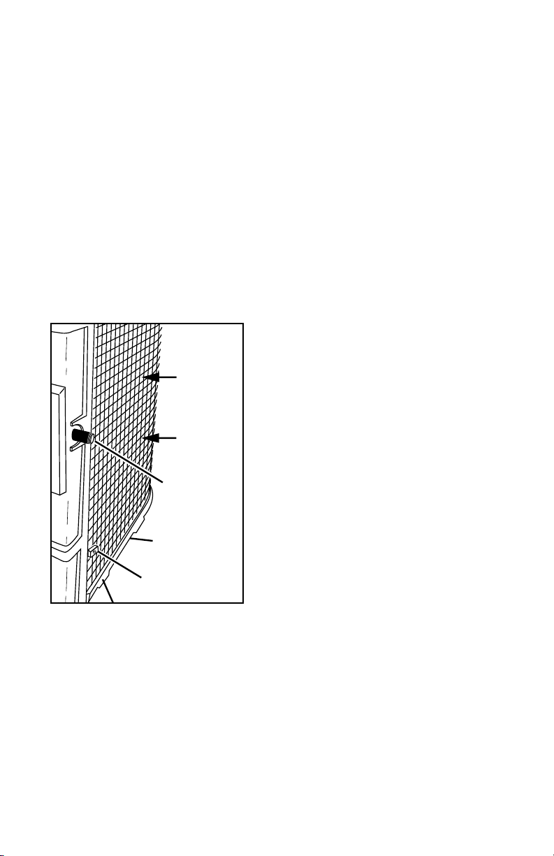
3.6 Electrical Bonding Requirements
Just like all other electrical pool equipment, Heat Siphon® must
be bonded (local earth grounding) and usually can simply be
tied into the existing bonding circuit with the pool pump etc..
NOTE: Electrical Bonding to a local earth
ground (separate from power supply
grounding) through a copper conductor
and to any other pool or spa system electrical equipment is required by Article 680
of the National Electrical Code.
Size - A solid copper conductor, insulated, covered, or bare, not smaller than
No. 8 (8.4 mm sq.) - 1981 Nat'l. Electric Code Art. 680-22(b)
Location - Heat Siphon® has a standard copper bonding lug located on the
right side of the unit facing the back panel. (See illustration at the beginning
of this Installer Section) This set screw type lug accepts standard #8 solid
copper wire . The copper wire should be connected to the bonding circuit of
BONDING LUG
WARM AIR
IN
ELECTRICAL
CONDUIT ¾” NPT
HAND HOLE
GRIPS
your other pool equipment.
See the lower right corner of the graphic
4 Special Installations
4.1 Indoor Pools
Heating an Indoor pool creates three problems:
1. The pool water must be heated,
2. The humidity is increased and the room must be dehumidified,
Installer - 22

HEAT SIPHON® Installer Section
3. In winter the room air must be heated.
Most of the heat lost from an indoor pool is a result of evaporation where the room temperature is not increased
but rather the room air becomes more humid, creating a condensation problem.
A dehumidifier cools the air down to condense the moisture out, and then reheats the air back to room temperature. The heat it extracts from the air is equal to the heat it puts back into the air except for a small amount of
excess heat converted from the electricity it consumes thus there is not enough heat to also reheat the pool water.
Gas pool heaters will heat the pool but provide no dehumidification and still require the room to be heated
separately.
Indoor installations of Heat Siphon® not only heat the pool, but provide the added benefit of dehumidification
of the pool room. When the Heat Siphon® cools down the room air to extract heat out of it, the moisture in the
air condenses on the cold evaporator, thus drying the air. But this requires the room air to be reheated and if the
room is small the Heat Siphon® may over cool the air and not operate very efficiently or it may require a fairly
large space heater.
If the room is large relative to the pool, there is usually sufficient heat in the air to keep the pool heated, BUT a
separate heat source must still be installed for the room air.
Since there is no wind the heat loss from the pool is significantly less than an outdoor pool. If a cover is used
on the pool, both the humidity and the heat loss will be greatly reduced to the point where run times of only a few
hours per day will maintain pool temperature.
NOTE - In any case your dealer should consult the Factory before planning any indoor pool Heat
Siphon® Installation and make sure there is enough air volume and an adequate source of space
heat to overcome the cooling effect.
4.2 Multiple Units
If connecting more than one Heat Siphon® on larger pools, the following applies in addition to the SPACE
requirements for single units:
• Feed all Heat Siphon’s from the same line (PUT THEM IN PARALLEL) and tie all of their water
outlets together. ENSURE EACH UNIT RECEIVES AT LEAST 25-30 GPM
• If piping (number of elbows and bends) are not identical to each unit then install a flow meter,
PVC couplings and shut off valves in each Heat Siphon® ‘s water line to permit balancing the flow
equally between units and to facilitate service and removal if required without shutdown of the pool
pumps.
CAUTION: In A Multiple Unit Installation Do Not Connect The Water Outlet Of One Heat Siphon®
To The Water Inlet Of The Next Heat Siphon®
This will create two problems:
FIRST - Series plumbing makes it impossible to correctly set the 2nd unit’s thermostat. The water leaving the
Installer - 23

HEAT SIPHON® Installer Section
From Pump
To Pool
Flow Meter & Balancing Valve on Each Unit Outlet
24” Minimum
Between Units
MULTIPLE UNIT INSTALLATIONS
Plumbing Must Be In Parallel - use same number of elbows with ow meter and balancing valve at each unit
Add
2” SCH 40
PVC Unions
to Inlet & Outlet
Water Fittings
SIZE MAIN FEEDER PIPES
FOR TOTAL FLOW RATE
first unit will be several degrees warmer than the pool. Thus the second unit’s thermostat will need to be set several
degrees higher than the desired pool temperature before it will turn on and it will cause cycling as the first unit
turns off and on. If both thermostats are set the same then the second unit will only run when the pool is colder
than the heat rise produced by the first Heat Siphon®.
SECOND - Series plumbing reduces efficiency of each Heat Siphon® downstream. - Warmer water removes less
heat from the Heat Siphon’s heat exchanger and requires the compressor to work harder. The highest efficiency is
achieved by feeding the coldest water to each unit (parallel piping does just that)
4.3 SPA Heating Issues - See APPENDIX D
SAFETY CONCERNS require special considerations when Heating a Spa or Hot Tub
Completing Installation
Assuming you have picked the best location and orientation and the necessary amperage electrical power supply
and bonding circuits are in place, the only work remaining is final wiring and plumbing of the Heat Siphon®.
4.4 Tools / Materials Required
The following is a suggested list of tools and materials normally required for Heat Siphon® installation. Additional tools and materials may also be required by unique or extraordinary pool sites:
• PVC pipe & fittings
• PVC cement & primer
• Hacksaw
• Wire cutter/stripper
• Pliers
Installer - 24

HEAT SIPHON® Installer Section
• Screwdriver ( phillips and flat blade)
• Circuit breaker with GFI
• Wire nuts
• Wire of size length and insulation required to meet local code
Normally the existing breaker box in the home electrical service or in the pool equipment panel has an available
breaker space. If not then you will need to install a new electrical breaker panel or fuse box.
4.5 Optional Recommended Materials
• 3/4 “ vinyl tubing for hose-barb condensation drain fitting in base pan
• Disconnect switch box if breaker not within site of the unit and/or local codes require it.
• PVC Unions or flexible couplings
4.6 Helpful Hints
IMPORTANT: ALLOW AT LEAST 12 INCHES OF STRAIGHT PVC PIPE GOING INTO AND OUT OF THE HEAT
EXCHANGER. Otherwise elbows or pvc couplings will prevent back panel removal and stop service access inside
the unit .This will also make repair of any plumbing problems very difficult and may require unnecessary heat
exchanger replacement since these are permanent glue joint fittings.
The following is a short list of suggestions which may prove time and money saving to the installer not only
during installation but throughout the life of the Heat Siphon®:
1. Installation of PVC unions or hose clamp type flexible couplings at the Heat Siphon® water inlet and outlet
lines is recommended to permit easy removal of the front panel if necessary for future service. ALLOW AT LEAST
12 INCHES OF STRAIGHT PIPE IN AND OUT OF THE UNIT BEFORE INSTALLING UNIONS.
2. Rigid PVC piping entering and leaving the Heat Siphon® SHOULD NOT BE IN A STRAINED OR BOWED
POSITION. Higher temperatures of the heated water can soften the PVC where solvent was applied (until it
is completely cured) and over time may cause glue joints to break open or leak.
3. Provide a means of draining the pool or spa water for winterizing. Unions are an excellent way to provide
drainage as well as easy service access. Draining the Heat Siphon® is recommend any time freezing temperatures are expected while the pool pump is off and no water is circulating.
4. Cut and fit all PVC pipe before any gluing is started. Use generous amounts of PVC cement and twist each
glue joint at assembly to ensure freedom from leaks. Don’t disturb a joint while the solvent is setting up.
5. If hard conduit is used to provide the electrical supply wiring , then terminate it with several feet of flexible
weatherproof conduit (such as sealtite) before entry to the Heat Siphon® junction box . This will allow back
panel removal without un-wiring the unit in the event future service is required.
6. Minimize the number of elbows used as this increases the pressure drop and pump back pressure.
7. Avoid installing the unit in locations where fences, decks or other structures that can cause air recirculation
may be added later and caution the pool owner to avoid such additions in the future.
8. Take the time to explain your installation to the pool owner and help fill out and send in the warranty card
. A little consumer education goes a long way to eliminate unnecessary service calls after you’ve done a
proper installation.
5 Final Power Line Wiring
Wiring to the TO COMPLETE WIRING remove the small gasketed Heat Siphon® junction box cover in the
Installer - 25

HEAT SIPHON® Installer Section
upper right corner of the front panel. Feed the wires into the junction box,
complete splicing with wire nuts and replace the cover.
CAUTION: Make sure the incoming ground wire is spliced to the Heat
Siphon® lead wire marked with the green tape or green insulation
and that the unit is bonded to a local earth ground.
6 Final Plumbing into Pool or Spa
IMPORTANT: Allow at least 12 inches of straight
pipe between the heat exchanger and any couplings or elbows to allow
backpanel removal for servicing .
NOTE. If the VERTICAL DISTANCE between the pool water level and the
Heat Siphon® is excessive (below or above 2 to 3 feet) your Heat Siphon®
may require adjustment of the water flow switch at installation (see initial
start up section).
Because of Heat Siphon’s exclusive FULL FLOW Titanium heat exchanger, it requires NO SPECIAL PLUMBING
arrangement and should be considered as just another length of PVC pipe in your pool filtration system.
The dual socket water ports allow you to glue either 1.5 inch or 2 inch (with a PVC 2” coupling) schedule 40
PVC pipe directly into the heat exchanger.
LOCATION: Connect Heat Siphon® in the pool pump discharge (return) line DOWNSTREAM of all lters and pool pumps,
and UPSTREAM of any electronic chlorinators or chemical pumps.
SIZE: All Heat Siphons have 1.5 “ x 2” ttings for connection to the pool or spa ltration piping. The in-line water
pressure drop produced by Heat Siphon is so low (less than 11/2 psi at 30 GPM) that as far as the pool pump is concerned
the Heat Siphon® can be considered equivalent to a few more feet of PVC pipe.
NOTE: THE HEAT SIPHON® REQUIRE NO BYPASS PIPING and NO SPECIAL Setting of FLOW RATES
as long as a minimum of at least 25-30 GPM is maintained during heating. Only on larger systems
where 2" PVC and 2.5 HP and larger pumps are used should a bypass be considered.
Installer - 26
HEAT SIPHON® Installer Section
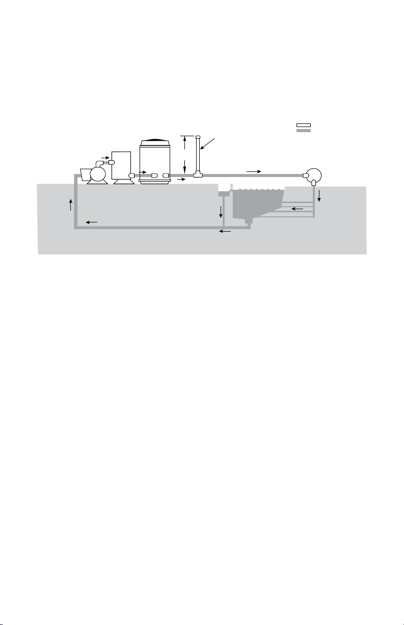
6.1 In Floor Cleaning Systems
Heat Siphon Plumbing Required
for In Floor Cleaning Systems
HEAT
PUMP
FILTER
SIPHON
36” MIN
WATER HAMMER
SURGE SUPPRESSOR
such as
STAND PIPE CAPPED
OFF WITH AIR INSIDE
PLUMBING KEY
AIR FILLED
WATER FILLED
IN FLOOR
CLEANING SYSTEM
SKIMMER
POOL
MAIN DRAIN
A special consideration must be given to in floor cleaning systems which can create water hammer as the multiport valves open and close. Water hammer damage is not covered by your warranty. It is up to the pool builder to
install the necessary plumbing features to protect your equipment from water hammer damage.
In these cases a vertical standpipe is recommended to reduce water hammer . Adding this plumbing feature is
simple and may prevent damage to the heat exchanger housing., however, it is not a guarantee against damage.
More effective and costly surge protection is available if the pool builder considers it necessary.
6.2 Pool Spa Combo Plumbing
The following pages shows several pool spa combination plumbing schematics. The first two pages show a single
pump and filter on a pool/spa combo with spillover feature and the last two show a two pump system.
Basically a Pool Spa combo is an installation where the two bodies of water have common plumbing allowing
the spa water to be dumped & diluted back into the pool or mixed with it for both filtration and heating considerations. Since the spa water is taken from and mixed with the pool water it will normally be at the pool temperature
as a starting point so it needs to only be heated from say 82°F to 102°F instead of the normal unheated water
temperature which can be much lower.
Single Pump Systems are simpler to plumb and only require two three way valves. They save energy (only one
pump needs to run) and thus are more common. The heating / filtering modes are limited to the pool, or the spa
or both pool and spa together.
Two pump systems require a second pump and filter, a third three-way valve and four check valves. They add
the ability to filter the unheated body of water while heating and filtering the other.
Installer - 27

HEAT SIPHON® Installer Section
POOL SPA COMBO
One Pump & Filter with Two 3-way Valves
P
Filter
HEAT SIPHON
P
Filter
HEAT SIPHON
Heating & Filtering Spa Only
Valves set - from spa to spa
Heating & Filtering Pool Only
Valves set - from pool to pool
COPYRIGHT 2012 All Rights Reserved United States ThermoAmp Inc.
1 Pump- Heating Pool or Spa
Installer - 28

HEAT SIPHON® Installer Section
HEAT SIPHON
Filter
P
HEAT SIPHON
Filter
P
COPYRIGHT 2012 All Rights Reserved United States ThermoAmp Inc.
POOL SPA COMBO
One Pump & Filter with Two 3-way Valves
Spill Over Mode
Valves set - from pool to spa
Spill Over Mode
Valves set - from pool to pool & spa
1 Pump- Spillover Mode
Installer - 29

HEAT SIPHON® Installer Section
P
P
P
Filter Filter
Filter
P
Filter
HEAT SIPHON
HEAT SIPHON
POOL SPA COMBO
Two Pumps & Two Filters with
Three 3-way Valves & Four Check Valves
Heating & Filtering Pool / Filtering Spa
Valves set from pool to heater to pool / from spa to spa
Heating & Filtering Pool / Filtering Spa
Valves set from spa to heater to spa/ from pool to pool
COPYRIGHT 2012 All Rights Reserved United States ThermoAmp Inc.
2 Pump- Heating Pool or Spa Only
Installer - 30

HEAT SIPHON® Installer Section
P
P
P
HEAT SIPHON
HEAT SIPHON
Filter Filter
Filter
P
Filter
POOL SPA COMBO
Two Pumps & Two Filters with
Three 3-way Valves & Four Check Valves
Spill Over Mode - Pool Pump Only
Heating & Filtering Pool & Spa
Valves set from pool to spa
Spill Over Mode - Both Pumps On
Heating & Filtering Pool & Spa
Valves set from pool to pool & spa / from spa to spa
COPYRIGHT 2012 All Rights Reserved United States ThermoAmp Inc.
2 Pump- Spillover Mode
Installer - 31

HEAT SIPHON® Installer Section
Initial Start-up
Please read completely through this section BEFORE STARTING UNIT.
IMPORTANT: Heat Siphon® is equipped with a ve minute built in solid state restart delay included to protect control circuit components
and to eliminate restart cycling and contactor chatter. This time delay
will automatically restart the unit approximately 5 minutes after each
control circuit interruption.
1 Initial Performance Checks
After installation is completed and the unit is ready to start, TURN OFF POOL PUMP and follow these steps:
1.1 First Startup of Analog Models
• Turn the Heat Siphon ® thermostat knob completely clockwise
• Turn on your filter pump, check for leaks and verify flow to and from the pool.
• Turn on the electrical power supply to the Heat Siphon® . The unit should start immediately.
The LED below the knob should turn on GREEN and slowly blink signifying that your Heat
Siphon is heating the pool or spa. If it is ORANGE and not blinking then it has power but no
flow has been detected and the water flow switch needs adjusted. If it is GREEN and blinking
it is in 5 minute restart delay
• Note : Even a brief power interruption will activate the solid state 5 minute restart delay and prevent
your Heat Siphon from starting until the count down is completed. A power interruption during the
delay period will have no effect on the 5 minute countdown.
• After running a few minutes make sure the air leaving the unit is between 5 to 10 degree F cooler
than ambient air - if not call dealer
• With Heat Siphon® operating, turn the filter pump off. Heat Siphon® should also turn off automatically and the LED should turn on SOLID ORANGE signifying that it is waiting for water flow
• If your Heat Siphon continues to run when the pump is off the LED will blink GREEN until the
overheat switch is tripped. It will then shut off and the LED will blink RED. You must adjust the of
flow switch (See section 1.3 below)
• Restart the pump/filter. The Heat Siphon ® should start right up - if not readjustment of flow switch
req’d. (See below)
• Allow the Heat Siphon® and pool pump to run 24 hours per day until desired pool water temperature is reached. At this point, slowly turn the thermostat knob counter clockwise until the unit just
shuts off and note the number on the dial. Your Heat Siphon& will now automatically restart (as
long as your pool pump is running) when the pool temperature drops more than 1.5 °F below the
set temperature.
In other words “SET IT AND FORGET IT.”
Installer - 32

HEAT SIPHON® Installer Section
1.2 First Startup of Digital Models
• Turn on the electrical power supply to the Heat Siphon®
• Display will read soft 1.xxx (the software version), then display flow & start delay countdowns.
• Press the Player "Up" or "Down" key until the desired water temperature is displayed
• Turn on your filter pump
• If the pool water temperature is below the Player set point, the unit should start immediately.
• The Player will display: "POOL" and the water temperature, then the "SET" and your desired water
temperature - if it is lower raise the set point above the water temperature.
• Check for leaks and verify flow to and from the pool.
• Note : Even a brief power interruption will activate the solid state 5 minute restart delay and prevent
your Heat Siphon from starting until the count down is completed. A power interruption during the
delay period will have no effect on the 5 minute countdown.
• After running a few minutes make sure the air leaving the unit is between 5 to 10 degree F cooler
than ambient air - if not call dealer
• With Heat Siphon® operating, turn the filter pump off. Heat Siphon® should also turn off automatically - if not readjustment of flow switch is Req’d. (See below)
• Restart the pump/filter. The Heat Siphon ® should start right up - if not readjustment of flow switch
req’d. (See below)
• Allow the Heat Siphon® and pool pump to run 24 hours per day until desired pool water temperature is reached. Your Heat Siphon will shut off and the POOL LED will be on solid Green.
• Your Heat Siphon will now automatically restart (as long as your pool pump is running) when the
pool temperature drops more than 1.5 °F below the set temperature.
1.3 Adjusting the Water Pressure Switch
Only one Heat Siphon® adjustment may be required at installation.
On some models of the Heat Siphon® a gas heater type water pressure sensing switch is used to detect flow
rather than direct flow measurement. The switch prevents Heat Siphon® operation with no water flow. Adjustment
is required when the vertical distance from the pool surface to the Heat Siphon® thermostat knob is more than a
few feet above or below pool level .
To correct this condition, DISCONNECT ALL ELECTRICAL POWER, remove the cover to the control box and
adjust the switch as follows.
1. If the pool is BELOW the unit and the Heat Siphon® won’t turn on with the pool pump, turn the pressure
switch adjustment thumb wheel to the right until the top of the switch is at the MINIMUM SETTING (1 psi).
2. If the unit still doesn’t start and it is more than 2 feet from the water surface to the thermostat knob then
the height difference may be creating a siphoning effect as the pool water returns to the pool, which in turn
lowers the pool return line pressure below the minimum trip pressure of this switch. In this case you may
need to create sufficient
Installer - 33

HEAT SIPHON® Installer Section
IF UNIT IS WELL ABOVE POOL WATER
IF UNIT IS WELL ABOVE POOL WATER
WATER PRESSURE SWITCH
Adjusting Water Pressure Switch - Unit Elevated Above Pool
YOU MAY NEED TO CREATE BACK
YOU MAY NEED TO CREATE BACK
PRESSURE TO TRIP THE FLOW SWITCH
PRESSURE TO TRIP THE FLOW SWITCH
(install eyeball sockets in return lines)
HEAT
SIPHON
(install eyeball sockets in return lines)
CONTACTOR
COMPRESSOR
RUN CAPACITOR
TRANSFORMER
TIME DELAY
(Pre-Timerstat
Analog Models)
PUMP
DISTANCE
FROM BOTTOM OF
CONTROL DOOR
TO POOL
SURFACE
POOL
1.4 Water Pressure Switch Location:
ELECTRICAL
CONTROL BOX
FAN MOTOR
RUN CAPACITOR
1
PSI
5
1
PSI
5
LOW PRESSURE
SWITCH
Wires not shown for clarity
HIGH PRESSURE
SWITCH
THERMOSTAT
(Pre-Timerstat
Analog Models)
Installer - 34
NEW SYLE
PLASTIC CASE
OLD SYLE
METAL CASE
Turn Wheel Clockwise to
INCREASE TRIP PRESSURE (FLOW)

HEAT SIPHON® Digital Player Section
Digital Player Section
This section of this Manual applies to all digital models and specifically details the operation of the Digital
Player Controller that is built into all Digital Models including Heating Only, Cooling Only and Heat/Cool Models.
1 Reading The Player Display
The Display is a 7 segment 4 digit LED which is easy to see in daylight as well as at night.
However, this does limit the words that can be displayed. Only capital letters “O, A, E L,C, S, F and U” and small
letters “b, d, o, l, i” are easy to represent & clearly understood. We also chose to use a representation of the letters
small “t, v, i and o” to broaden the number of words the Player can display but they are not as easily recognizable.
Here are the more confusing ones:
Heat ............
Set .............
Cool ............
Volt .............
On In ............
Soft (software version) ........
1.1 The Player Display Info
Normally the Player continuously displays three bits of information - the MODE , the water temperature and
the set point. For example, if your pool is 78°F and you have set the pool temperature to 88°F and you are in POOL
Digital Player - 35

HEAT SIPHON® Digital Player Section
mode, then following message is displayed:
Screen Message ..................................... Duration
POOL ..............................................(2 second)
78°F ................................................(2 second)
HEAT ...............................................(1 second)
SET. . . . . . . . . . . . . . . . . . . . . . . . . . . . . . . . . . . . . . . . . . . . . . . . . (1 second)
88°F ................................................(2 second)
If errors occur or event timers are active they take precedent. All common Error codes are listed on the decal
along with their meaning.
One of the timers that you will see is the Off timer. This is a 240 second (4 minute) countdown that will occur
anytime the Heat Siphon turns off either in the background or shown directly on the display. This is a safety
feature that allows the internal pressures to equalize before restarting. You will see it as, OFF, 239, 238, 237, 236,
OFF, 234, 233 etc.
Another timer you will see is the FLO timer. This is a 15 second timer that begins when the water pump turns on.
This is to give the water pump time to push all the bubbles through the system and achieve good water flow before the
Heat Siphon turns on. You will see it as, FLO, 14, 13, 12, 11, FLO, 9, 8, 7, 6 etc. Modes: (POOL, SPA, AUTO PIC, OFF)
1.2 LED STATUS Lights
The Player has 4 LED lights located just above the top of the 4 digit display window which are labeled from left
to right :
BLUE LED - Wireless PumpJump™ flutters blue when a wireless accessory is attached and communicating
to a PassPort OR is solid ON when timeclock over-ride is activated using a hardwired T type or S-Type POD (Pool
Operating Device)
RED LED - Service blinks when an error is detected and service call is required or an error /warning requiring
user intervention has been detected
GREEN LED - Signifies the Player is in POOL MODE or in AUTO-PIC Mode with POOL Selected and is heating
your water to the POOL set point
YELLOW LED - signifies the Player is in SPA MODE or in AUTO-PIC Mode with SPA Selected and is heating
your water to the SPA set point
The GREEN (pool) and YELLOW (spa) LED’s also signifies what “state” the Player is in based on what
they are doing:
LED ON SOLID that means the pool or spa is at temperature and READY to use.
LED IS BLINKING SLOWLY (1 second on/off) indicates that the Player is heating your pool or spa but
has not yet reached temperature.
LED IS FLASHING RAPIDLY (1/2 second on 1/2 second off) indicates the Player is waiting to change
state such as when a countdown timer is active but your Heat Siphon has not yet turned on.
Digital Player - 36

HEAT SIPHON® Digital Player Section
One special case which also displays the message “no FLo” (no water flow detected) which is technically an
“error “or “warning” if the flow is unintentionally interrupted. Normally your Heat Siphon is simply waiting
to detect flow when the pool pump turns on so we have chosen to rapidly flash the POOL or the SPA LED while
displaying this message.
The industry standard water pressure switch that is used by all heaters to detect whether the pump is on, cannot
necessarily distinguish between no flow (waiting for flow) and low flow (pump or filter troubles) which is an error.
In this case, low flow will result in a High Refrigerant pressure which trips that switch it will appear as a Hi P error
and the red LED will flash.
2 Changing Pool Temperature
Press the UP or DOWN arrow key at any time and you will instantly see the current water temperature set point
displayed and it will begin blinking. Any additional key presses while it is blinking (within 3 seconds) will raise
(up arrow key) or lower (down arrow key) the set point.
Simply change the set point by pressing the keys until the temperature you want is displayed
No key press for three seconds will store the displayed temperature as the new set point with a confirming “BEEP”
If you made no changes then there will be no “BEEP” and after three seconds the display will continue to scroll
through its normal messages
2.1 Changing Units (°F / °C)
Press and hold BOTH keys at the same time for THREE SECONDS you will hear a rapid beep-beep-beep etc.
Continue pressing until the right most digit displays “F” or “C” then IMMEDIATELY RELEASE BOTH KEYS and
press up or down to change units. No key press for three seconds will change to the displayed units, “F” or “C” and
the Player will BEEP confirming that it has accepted your change.
3 Player Operating Modes
The Player has FIVE MODES: POOL, SPA, AUTO-PIC, EC and OFF. Pool and Spa modes automatically HEAT (
and/or COOL with Dual or Chiller models) a Pool or Spa to a set temperature and will turn on only when water
flow is available and turn off when the desired water temperature is reached.
No matter what MODE your Player is in, it will not allow your Heat Siphon to run if there are any safety switches
tripped or errors. That means there must also be water flow and air above 45°F to 50°F. Switching between any
mode is normally not necessary or recommended unless you have a pool/spa combo and are using manual 3 way
valves to switch from pool to spa or spill over mode.
3.1 POOL Mode
POOL and SPA modes are basically identical except that each has a separate temperature range and set point.
In POOL mode uses the GREEN LED light to indicate status (SEE LED Status Lights above)and the use of the
word POOL in the water temperature display, example - "POOL ". . . "78F" . . "HEAT". . SET" . . "80F"
Digital Player - 37

HEAT SIPHON® Digital Player Section
• POOL mode will heat to the desired POOL set point then shut off your Heat Siphon.
• Switching between POOL and SPA does not erase the other mode’s set point.
• POOL can be set from 50°F(10°C) to 98°F(36°C)
3.2 SPA Mode
In Spa mode, the YELLOW LED light to indicate status (SEE LED Status Lights above) and the use of the word
SPA in the water temperature display, example - "SPA ". . . "98F" . . "HEAT". . SET" . . "102F"
• SPA mode will heat to the desired POOL set point then shut off your Heat Siphon.
• Switching between SPA and POOL does not erase the other mode’s set point.
• SPA mode will heat to the desired SPA set point then shut off your Heat Siphon.
• SPA can be set from 50°F(10°C) to 104°F(40°C)
3.3 OFF Mode
The OFF mode is just that - your Heat Siphon will remain OFF no matter what the water temperature or set point
and will not display anything other than “OFF” . Once any key is pressed, the Player will restart into the last known
mode before OFF was chosen. And the 240 second Off timer will begin.
3.4 AUTO-PIC Mode
AUTO or AUTO-PIC Mode is a way for the Heat Siphon to decide, on its own, what body of water you are heating
(pool or spa) and then heat that body of water to the correct set point (pool set point or spa set point). This is a
convenience feature and the goal is to allow you to simply turn your pump off, switch your valves to pool or spa,
and turn your pump back on. The Heat Siphon will do the rest.
3.4.1 How AUTO PIC Works
• In AUTO-PIC mode, every time the water pump turn on, the Heat Siphon Player begins the auto-pic
algorithm to decide what body of water it is heating.
• This usually takes approximately 5 minutes.
• AUTO-PIC works the same as pool or spa modes except it also will automatically pick the pool or spa
set point based on a learning algorithm.
3.4.2 AUTO PIC LED lights and display
When the Player is in AUTO-PIC, or waiting to go into AUTO-PIC, both the green (pool) and yellow(spa) LED
lights flash at the same time: 1 second on/off - if it is waiting for a timer to expire
0.5 sec on/o - once it turns on and starts AUTO-PIC
Once POOL or SPA mode is chosen by the Player, it will stop flashing both lights and turn on either the GREEN
(POOL) or YELLOW (SPA) LED
The Player message display loop will show the POOL and SPA set points in the normal sequence and then the
water temperature preceded by “Auto Pool” , “Auto Spa” or just “AUTO-PIC” if neither set point has been chosen.
The message display loop will be as follows:
Digital Player - 38

HEAT SIPHON® Digital Player Section
Mode not Selected
Display .............................................. Duration
AUTO ...............................................1 second
HEAT ................................................1 second
78°F .................................................2 second
POOL ...............................................1 second
SET. . . . . . . . . . . . . . . . . . . . . . . . . . . . . . . . . . . . . . . . . . . . . . . . . . 1 second
88°F .................................................2 second
SPA .................................................1 second
SET. . . . . . . . . . . . . . . . . . . . . . . . . . . . . . . . . . . . . . . . . . . . . . . . . . 1 second
102°F ...............................................2 second
Pool Mode Selected
Display .............................................. Duration
AUTO ...............................................1 second
POOL ...............................................1 second
78°F .................................................2 second
POOL ...............................................1 second
SET. . . . . . . . . . . . . . . . . . . . . . . . . . . . . . . . . . . . . . . . . . . . . . . . . . 1 second
88°F .................................................2 second
SPA .................................................1 second
SET. . . . . . . . . . . . . . . . . . . . . . . . . . . . . . . . . . . . . . . . . . . . . . . . . . 1 second
102°F ...............................................2 second
SPA Mode Selected
Display .............................................. Duration
AUTO ...............................................1 second
SPA .................................................1 second
78°F .................................................2 second
POOL ...............................................1 second
SET. . . . . . . . . . . . . . . . . . . . . . . . . . . . . . . . . . . . . . . . . . . . . . . . . . 1 second
88°F .................................................2 second
SPA .................................................1 second
SET. . . . . . . . . . . . . . . . . . . . . . . . . . . . . . . . . . . . . . . . . . . . . . . . . . 1 second
102°F ...............................................2 second
In AUTO-PIC mode, you can change the set points for either POOL or SPA at any time, by pressing the up OR
down arrow WHEN THE POOL or SPA SET POINT you wish to change is displayed. Just like in Pool or Spa mode,
three seconds after your last keypress your new set point will be accepted with an audible beep. OFF mode:
3.5 EC Mode (External Control)
If you elect NOT to use Heat Siphon Brand Digital / Wireless Pool/Spa Controller Accessories, using the EC mode,
you can still interface your Heat Siphon’s Player Control Board with any other 3rd party pool/spa control systems.
For more information on how to install and wire 3rd party controller interfaces into the Player, see the EC MODE
Instruction Sheet
EC mode which stands for EXTERNAL CONTROL will ONLY TURN ON your Heat Siphon IF there is water flow
AND your 3rd party controller’s dry contacts are closed AND the MAX set point of the Player has not been exceeded.
Digital Player - 39

HEAT SIPHON® Digital Player Section
It will stay on until either the MAXIMUM EC set-point is reached or your controller shuts it off.
ALL ERROR MESSAGES WILL STILL BE DISPLAYED. You set the MAX EC set-point on your Player with up/
down keys.
Once you place the Player in EC mode it will continuously display “EC” and the water temperature or “OFF”
if your Heat Siphon is not running.
3.6 TEST Mode
WARNING - DO NOT ENTER TEST MODE.
TEST mode is for factory authorized service personnel use only.
Factory Service phone support may ask you to enter test mode to diagnose a problem and guide you through
the process including exiting test mode. Without this support you should NEVER use or enter Test Mode since it
can override safety controls.
If you accidentally enter test mode you should exit immediately by doing the following:
1. Repeatedly pressing and releasing EITHER the up or down arrow key until the word TEST (tESt) reappears
in the display.
2. Then press and release both keys at the same time.
3. This will result in the Player rebooting to normal operation using the last selected MODE.
NOTE: IF YOU CAN NOT EXIT TEST MODE CALL THE FACTORY IMMEDIATELY
4 Switching Modes
4.1 Pool/Spa/Auto/O
1. Press both keys WHEN THE MODE IS DISPLAYED (POOL/SPA/AUTO) which will cause the current mode
to blink for 3 seconds.
2. Press and release EITHER up or down key while blinking to cycle to the next mode including OFF.
3. You now have 3 seconds to press the up (or down) arrow.
4. Press and release the up (or down) arrow to scroll through the four different modes.
5. The modes are: POOL, SPA, AUTO PIC, and OFF.
6. Three seconds after your last keypress, the displayed mode will be accepted with an audible beep.
7. Notice that the lights will change to match the mode.
NOTE: EC Mode is not displayed in the normal MODE scrolling list. Entering EC mode requires additional
steps - see next below for details.
4.2 Entering EC Mode
The following procedure is used to allow a 3rd party controller to turn your Heat Siphon on and off. First, you
must put your Player in the OFF mode using the ”Switching Modes” instructions above.
NOTE: In "EC" mode, the thermostat will still turn your Heat Siphon off when its set point is reached. If you do
not want to use the built in Thermostat set point you must raise the set point above the 3rd party controller tempera-
Digital Player - 40

HEAT SIPHON® Digital Player Section
ture range. The thermostat then becomes a safety switch and it's set point is now referred to as "MAX EC" set point
1. From the OFF mode, press and release BOTH keys, which will cause “OFF” to blink for 3 seconds.
2. WHILE “OFF” IS BLINKING , press any key to display “On” then press BOTH keys to get “EC” to display.
3. You should then see “EC” followed by the current water temperature constantly repeated.
4.2.1 Changing MAX EC set point
In EC Mode, if the water temperature reaches the MAX EC set point it will shut off your Heat Siphon and ignore
the 3rd party controller until the water temperature goes back down below the MAX EC set point.
1. To display/change the MAX EC set point, press any key while in EC mode, which will cause the MAX EC set
point to blink for 3 seconds.
2. Any additional key presses while it is blinking will change the MAX EC set point by pressing up or down key
3. After any key has been pressed in EC mode , the MAX EC set point will be added to the display message using
the words “HEAT” “SET” and the MAX EC set temperature.
4. This will continue for message three cycles, after which it will revert back to simply displaying “EC” and the
current water temperature.
4.2.2 Manual OFF in EC Mode
You can turn your Heat Siphon “OFF” manually while it is in EC mode so it will remain off and ignore any 3rd
party controller by using the ”Switching Modes” instructions above:
1. While in EC Mode - Press and release BOTH keys causing “EC” to display & blink
2. Within 3 seconds press either key to display “OFF”.
3. When Blinking stops it is in EC Manual - OFF.
4. To turn EC mode back on from this “manual off” EC state, simply repeat the process
5. Press and release BOTH keys causing “OFF” to start blinking
6. Within 3 seconds press either key to display “EC”.
4.2.3 Exiting EC Mode
If you have either accidentally entered EC Mode or wish to return to your regular Heat Siphon Player Controller
mode, you must EXIT EC Mode by performing the same sequence of key presses as used to enter EC mode:
1. First, you must put your Player in the OFF mode by Pressing & releasing BOTH keys to make “EC” blink then
press either key to display “OFF” - wait until it stops blinking before proceeding.
2. From the OFF mode, press and release BOTH keys, which will cause “OFF” to blink for 3 seconds.
3. WHILE “OFF” IS BLINKING , press any key to display “EC” then press BOTH keys to get “On” to display. .
4. You should then see the PLAYER REBOOT and go through a normal startup sequence.
4.3 Switching Modes - For Heat/Cool Units Only
1. Press the UP or DOWN ARROW KEY to make the temperature set-point blink.
2. WHILE the TEMPERATURE is BLINKING, press and release BOTH keys at the same time . The display will be
blinking either HEAT or COOL or DUAL (duAL).
3. Press and release EITHER up or down key while blinking until the desired mode is displayed.
Digital Player - 41

HEAT SIPHON® Digital Player Section
4. If you are in COOL mode the lower right-hand corner of the display will have a red dot on all the time to
show that you are in COOL mode. The same applies to COOL mode while in DUAL mode.
4.4 Locking the Player
1. To lock the Player, press and hold both arrow keys until you see LOC on the display (six seconds), then
release both keys.
2. Three seconds after you release, LOC will be accepted with an audible beep.
3. Your keys are now locked. The display will continue to show the current Temperature/set point loop and
continue to heat your pool or spa as needed, however any keypress will show LOC on the display.
4. To unlock the Player, simply press and hold both arrow keys for six seconds until you hear a beep, then
release both buttons
5. The Player is now unlocked
5 Special Settings in TEST mode
For some special cases the Heat Siphon Player has two Spa settings. These are in the Test Mode They are listed
below and should only be enabled by the dealer:
1. C-SPA setting - In the case of a remotely heated spa where the plumbing run is long ands
thus the spa water temperature drops a few degrees before it gets to the Heat Siphon the
set point may need to be reduced to prevent overheating due to a phenomenon called
THERMOSTAT SET POINT DEPRESSION - SEE APPENDIX D of this manual for details.
2. H-SPA setting - The default maximum spa set point from the factory is 102°F. You may
change this to 103 or 104°F using this setting HOWEVER, be sure to read the SPA HEATING
cautions in Appendix D of this manual before using this option.
To enable these features ask your DEALER or CALL THE FACTORY.
6 Commercial Player Spa Modes
For spas in condominium/home owners associations, rental houses, hotels and other commercial applications,
Heat Siphon Player provides an additional feature to help a non-resident or absentee owner with the ability to manage
energy use when heating a stand alone spa. This is the S-SPA menu for Stop Spa Mode which includes Timed Spa
Heating Mode or "tSPA" as it appears on the 7 segment 4 digit LED.
S-SPA Menu is designed to limit the amount of time the Heat Siphon will stay in the SPA Mode (heating to the
SPA set point), after which Heat Siphon will revert back to the POOL Mode and heat to its set point.
6.1 STOP SPA Option
The hours chosen in the STOP SPA or S-SPA menu (0 , 2, 4, 6 or 8 Hours and Timed SPA or "tSPA"). You can
choose S-SPA menu is accessed as
1. holding down both keys until SSPA is displayed.
2. Release both keys and use the up or down arrow keys to scroll through the options
3. Options are as follows:
"0" - Stop SPA Off - Normal Switching between POOL and SPA required
Digital Player - 42

HEAT SIPHON® Digital Player Section
"2" - After 2 Hours Heat Siphon will switch back to POOL MODE and set point
"4" - After 4 Hours Heat Siphon will switch back to POOL MODE and set point
"6" - After 6 Hours Heat Siphon will switch back to POOL MODE and set point
"8" - After 8 Hours Heat Siphon will switch back to POOL MODE and set point
"tSPA" - this choice will put the Heat Siphon in Timed SPA Mode - see below for details
4. 3 seconds with no keypress will accept the option displayed and return you to normal display.
6.2 T-SPA - Timed SPA Mode
T-SPA mode limits the user interface to only two functions - (1) setting the spa temperature in the heat-up period
then (2) setting the spa heating time in 15 minutes increments up to 90 minutes in the count down period. No
other features are accessible when the Player is in T-SPA mode and it must be "unlocked" to revert back to normal
Player behavior.
There are only three states in the T-SPA mode: - HEAT-UP, COUNTDOWN and IDLE.
Here is how the Player works when in T-SPA mode assuming it is in the IDLE state:
1. The first button press (up or down keys) will change the spa temperature( after 3 seconds
with no key press)
2. If the water temperature is below the spa set point, the Heat Siphon will turn on and begin
heating to the set point. This is the HEAT-UP state
3. While it is heating AND before it reaches the set point temperature the user may change
the set point up or down. If it is set down below the water temperature, the Heat Siphon
will shut off and return to IDLE t-spa state. if it is set higher, it will continue heating.
4. Once the spa water reaches the set point, the Heat Siphon will shut off and enter the
COUNTDOWN state, where it will count down from 15 minutes to zero. and display the
time left. Any button presses in the count down period will only change the time remaining
in the countdown. Each button press will add (up arrow key) or subtract (down arrow
key)15 minutes to/from the timer.
5. If the water temperature falls below the set point in COUNTDOWN state the Heat Siphon
will turn back on and heat up to the existing set point.
6. When timer stops, the T-SPA enters the IDLE state and it will maintain the "POOL" set
point which was last set before entering the T-SPA mode.
Thus SPA heating will be limited by time and will automatically drop back to the pool temperature set point such
as 82°F . For example , if the pool set point is 82°F, only a 20°F rise is needed to get to 102°F instead of starting
from cold water. In addition, users can't forget to turn off the Heat Siphon when they are done using the spa, since
it is always timed to go idle.
Call Factory for T-SPA mode unlocking instructions.
7 Error and Warning Codes
When the red “Service’ LED flashes (or the Green LED flashes only in the case of NO FLOW), an error or warning
message appears on the 4 digit, 7 segment LED display.
Most of the following error codes are listed on the left side of the Player Control decal. Some may be added in
Digital Player - 43

HEAT SIPHON® Digital Player Section
later software updates and may not be on your decal. See our website for latest error codes.
There are three different types of error codes displayed by the Digital Player Controller. Below is a more detailed
description of these error code:
WARNING CODE - The Warning Code is displayed for the duration the error exists, takes no actions and
is self-correcting which means it disappears when the condition that caused it does. This error is not counted or
stored in memory.
ALERT CODE - SELF-CORRECTING ERRORS - The ALERT CODE is displayed while the error condition
exists same as a warning except the Player shuts down the contactor which turns off the Heat Siphon until the
condition disappears. This error is counted and stored.
SERVICE CODE - ERRORS REQUIRING USER INTERVENTION - These are Service Codes that
turn off the Heat Siphon until either the UP or DOWN arrow key is pressed. Then the Player restarts the unit and
the error code goes away. This error is counted and stored.
NOTE: In the case of SERVICE CODES, a four digit number is displayed
following the error code which indicates the total number of times that
error has occurred on your Heat Siphon since it was installed.
7.1 Low Refrigerant Pressure (Lo P)
Low Pressure (Lo P) - self-correcting
ALERT CODE - Heat Siphon is equipped with a low pressure switch within the refrigeration system, which is
designed to detect a refrigerant leak or a fan motor failure or air blockage by (low air flow) or prevent operation
when icing can occur in low air temperature.
• If the pressure goes below a set value it opens and the Player will shuts off the Heat Siphon.
• This switch will auto-reset at a slightly higher pressure.
Possible Causes
• If there is a refrigerant leak the pressure will drop until the switch stays open preventing the unit
from starting
• If the leak is very small the pressure may stay above the trip point and allow the compressor to start
but as it sucks the low side down below the switch trip point it will then shut down.
• If the fan motor is not turning or moving slowly this will also lower the pressure tripping the switch
and shut down the unit. In this case turn unit on to see if fan motor is hesitating or making noise,
or not turning.
• If fan motor is turning slow or making noise it will need replaced.
• If the fan motor is not starting at all it may just need a fan capacitor replacement.
Cycle Low Pressure (Cy Lo)
SERVICE ERROR - If the Lo P error occurs 3 times in 60 minutes the error becomes a Cycle Low Pressure error
and the unit shuts down until a key is pressed. Any time during the hour if a key is pressed the count is reset to zero.
Digital Player - 44

HEAT SIPHON® Digital Player Section
7.2 Low Air Temp. Warning (Lo A)
Low Air Temperature (Lo A)
ALERT CODE - As the air temperature drops the suction pressure will drop at some point below the Low
Pressure switch trip point and the Player will shut the unit down.
• If the Outside Air Temperature is Below 50°F when the low pressure switch trips, it is a Low Air Error
and the Player will display Lo A instead of Lo P
• When the pressure switch resets the Heat Siphon will restart on its own (if your pool pump on) This
may occur at up to 55°F
• After the air temperature rises 2 °F above its trip temperature the Player will allow the unit to
restart°F for 10 seconds when the Low Pressure switch has reset due to pressure increase from air
temp rise.
• If the switch does not reset, the Heat Siphon will shut down and will display Low Air (Lo A)
Cycle Low Air (Cy A)
ALERT CODE / SERVICE ERROR - If the Lo A error occurs 3 times in 60 minutes the error becomes a
Cycle A Error, however, unlike the Cycle Lo P error it may reset if the temperature rises.
• If any button is pressed at any time during the Cy A period, the Player will reset the count to zero and
begin again.
7.3 High Refrigerant Pressure (Hi P)
ALERT CODE - Heat Siphon is equipped with a refrigeration high pressure switch to detect low water flow.
• If the pressure goes above a set value it opens and shuts off the Heat Siphon. This switch will auto-reset at a slightly lower pressure.
• If this error occurs 3 times in 30 minutes the error becomes a type 3 error Cycle High Pressure and
the unit shuts down until a key is pressed.
Possible Causes
• WATER FLOW RESTRICTION could causing the Heat Siphon to shut down on high refriger-
ant pressure because the water is not removing enough heat.
• Check to make sure you do not have any bypass valve or any valves are in an incorrect position
which is causing flow restriction
• Check pool filter pressure gauge -Rule of thumb Sand filter low than 25 psi, Cartridge filter lower
than 15 psi , Earth Filter lower than 18 psi
• In Floor cleaning system valves not working properly
• PUMP DEADHEAD CONDITION - would “fool the water pressure switch” and the Player
would allow unit to run with no water flow thus tripping the high pressure switch
• WATER PRESSURE SWITCH MALFUNCTION - Check the water flow line inside the Heat
Siphon (clear or black hose leading from the component control panel to the bottom of the Heat
exchanger)by taking off end of hose connected to the water flow switch to verify it is free of debris
• If Water flow checks out OK, then the high pressure switch could be out of calibration and need
Digital Player - 45

HEAT SIPHON® Digital Player Section
replaced.
• TXV (expansion valve) FAILURE -Refrigeration part and Air conditioning company is
required for the replacement due to Refrigerant
• WATER VAPOR IN SYSTEM - If unit was recharged with R410A in the field and possible water
vapor contamination occurred, the TXV will be blocked by the water if it turns to ice (at low air
temperatures and it will unblock as the ice melts. Unit must be recharged.
7.4 Low Water Flow (Lo / FLO)
ALERT CODE - Water flow is either restricted or low enough to cause the water pressure switch or flow sensor
to trip open.
• To verify the problem is water flow in the case of the water pressure switch, try creating some back
pressure to decrease flow by closing off one of your return lines.
• Check your pool pump basket make sure it is clean
• Clean, Bump, Etc your pool Filter
• Make sure your skimmer basket is clear
• Water pressure switch hose has become disconnected from the back panel control box or bottom of
heat exchanger
7.5 Water Sensor Open (SH o)
ALERT CODE - The Thermistor used to measure water temperature in the heat exchanger thermostat well
has an open circuit meaning a break in the wires somewhere between the Player and the sensor.
• Usually this requires the sensor to be replaced.
• Check connection in control panel make sure the terminals are connected tightly
7.6 Water Sensor Short (SH S)
ALERT CODE - The Thermistor used to measure water temperature in the heat exchanger thermostat well has
a short circuit somewhere between the Player and the sensor or possibly water has permeated the sensor.
• Usually this requires the sensor to be replaced.
• Check connection in control panel and the wire cable for crimps and make sure the terminals are
not touching bare wires or other metal which might cause a short.
7.7 High Volts (H i / UoLt)
ALERT CODE - High voltage from the transformer greater than 31.2 VAC to the Player Board for more than
4 seconds will cause this error message to appear
• Verify correct power connection to Heat Siphon and the transformer
• Voltage surges may cause this temporarily
Cycle High Volts
SERVICE ERROR - If Hi Volts error occur 3 times in 30 minutes the error becomes a type 3 error - cycle voltage
and the unit shuts down until a key is pressed. This is usually caused by improper power supply installation wiring
Digital Player - 46

HEAT SIPHON® Digital Player Section
7.8 Low Volts (Lo / UoLt)
ALERT CODE - Low voltage from the transformer less than 19.2 VAC to the Player Board for more than 4 seconds.
• Verify correct 220 Volt power connection to Heat Siphon and the transformer
• Check for corrosion of quick connects
• Voltage brownouts may cause this temporarily
Cycle Low Volts
SERVICE ERROR - if they occur 3 times in 30 minutes the error becomes a type 3 error - cycle voltage and
the unit shuts down until a key is pressed. This is usually caused by improper power supply installation wiring
7.9 Main Contactor Short (HS S)
ALERT CODE - The two wires going from the Player to the Heat Siphon’s 24 volt AC main contactor coil has
a short circuit.
• Possible burnt wire to contactor or other wires shorting out
• Rodent infestation in control box
7.10 Main Contactor Open Circuit (HS o)
ALERT CODE - The two wires going from the Player to the Heat Siphon’s 24 volt AC main contactor coil are
open, no coil resistance is detected.
• Possible burnt wire to contactor
• contactor not making connection to start the compressor
• Rodent infestation in control box - wires gnawed through
7.11 Can’t Heat (CAnt / HEAt)
WARNING CODE - occurs when Heat Siphon has been running for 24 Straight hours with no water tem-
perature gain or a temperature loss and is usually due to one of the following reasons:
• Your pool is to large for the Heat Siphon model installed
• You are adding water to pool causing water temperature to drop
• Air temperature is too cool, to much heat loss, add a solar blanket
• This error is self-correcting, does not shut down the unit and will disappear when the water temperature rises. Its main purpose is to alert the pool owner of an abnormal heat loss or a sizing error.
7.12 Air Temp Sensor Open (SA o)
WARNING CODE - applies to the earlier version of the player board which used a thermistor held by two
screw-down terminals to detect air temperature. It was to make sure the sensor wire are not touching or loose from
screw down terminal.
• All boards made after August 2006 use surface mount thermistors which virtually eliminates this
error.
• If you can’t correct this error by replacing the thermistor, a new Player is required
Digital Player - 47

HEAT SIPHON® Digital Player Section
7.13 Air Temp Sensor Short (SA S)
WARNING CODE - See Air Temp Sensor Open Error above.
7.14 No POD (no / Pod)
SERVICE ERROR - No Pod Service Code means the Heat Siphon is looking for an external hardwired add
on Pod (See Accessories - J-POD, T-POD, S-POD) and it is shutting the Heat Siphon down because it has been
controlling a pump and no longer can detect or control the pump so to be on the safe side it shuts the heater and
POD terminals down and waits for user interaction.
• The error without a POD attached is rare but usually due to a power surge from storm, etc..
• This is easy to reset.
• Hold both Up and Down arrow keys at the same time
• As soon as they blink-hit the up or down key to scroll thru, Pool- Spa -Auto Pic
• Then you will see OFF. Stop at OFF and let the Heat Siphon shut OFF.
• Then Hit the up key 2 times to On.
• Heat Siphon will restart, go thru count down and NO POD error will be gone.
• The display will now go into its normal startup display and will show soft and software version
number then flow count down, then go into its time delay count before restarting
7.15 PumpJump Coil Short (PJ S)
ALERT CODE - The two wires going from the Player POD screw down terminals to a J-POD have a short circuit.
• You must have a J-POD for this Error to Occur.
• Check wiring and crimped wire connections for a short
7.16 No Flow w/ Pump Jump(Lo F / Pod)
ALERT CODE - Flow has NOT been detected with the J-POD, T-POD or S-POD connected while the Player is
sending the POD a 24 volt signal to turn the pool pump on
• Check connection on back of Player - wires should be connected to the “O” and “D” screw down
terminals.
• POD Toggle switch could be set to OFF which overrides Player signal keeping pump off
7.17 Flow w/ Pump Jump (FLO / Pod)
ALERT CODE - Flow has been detected with the J-POD, T-POD or S-POD connected while the Player is NOT
sending the POD a 24 volt signal to turn the pool pump on
• Check connection to Player - wires should be connected to the “O” and “D” screw down terminals
• POD Toggle switch could be set to ON which overrides Player signal and keeps pump on
7.18 Pod Coil Open (no / Pod)
ALERT CODE - An open circuit has been detected with a J-POD, T-POD or S-POD connected to the Player
• check connection on back of board
• wires should be connected to the “O” and “D” screw down ports.
Digital Player - 48

HEAT SIPHON® Digital Player Section
7.19 High Air Temperature (Air / Hi)
ALERT CODE - Temperature inside of player pocket is too warm. Heat pump remains functional.
• This error code has been deleted from the latest Player software. - Software update required
7.20 Low Air Temperature (COLD / xxF)
ALERT CODE - Air Temperature (biased on thermistor inside of player pocket) is too cold
• air temp < 41 and unit ran for 15 minutes
• self correcting when air temp >= 43
7.21 Reversing Valve Coil Open (CH o)
ALERT CODE - For HEATING / COOLING MODELS ONLY the reversing valve is open circuit
• Check wiring , replace coil
7.22 Reversing Valve Coil Short (CH S)
ALERT CODE - For HEATING / COOLING MODELS ONLY the reversing valve is short circuit
• Check wiring , replace coil
7.23 Easy Pic/Clock No Board (no / EASy)
ALERT CODE - An Easy Pic or clock board is required to be plugged into the Player for a T-POD or S-POD
to function properly but no board is not detected
7.24 Circuit Board Errors
The following are hardware errors detected by the software and most likely require that the Player board be replaced
• Board OPEN - Heat Siphon - (Brd1)
• Board OPEN - Reversing Valve - (Brd2)
• Board OPEN - POD - (Brd3)
• Board SHORT - Heat Siphon - (Brd4)
Check controls in control panel for loose wires
• Board SHORT - Reversing Valve - (Brd5)
Check back of board fort loose connection at REV Valve screw down connection
• Board SHORT - POD - (Brd6)
Check back of board for loose connection at POD screw down connection.
Digital Player - 49

HEAT SIPHON® TimerStat Pro Section
Analog TimerStat Pro Section
1.1 Still Keeping it Simple
The NEW TIMERSTAT PRO Analog Models of Heat Siphon are basically the same as the digital models from a
heat pump component standpoint, however, the electronic TimerStat Pro controller is designed as a modern version
of Heat Siphon's very first models produced in the 1980's.
In keeping with these original Analog units, the controls were kept as simple as possible - ONE KNOB - which
lead to a more reliable simpler to repair and troubleshoot heat pump. The New Timerstat Pro also has just ONE
KNOB - albeit a stainless steel version and just one Status Light right below it, which is a tri color RED - GREEN
-ORANGE LED.
The controller monitors the same Low & High Refrigerant Pressure Switches and Water Flow Switch, and it uses
the same very accurate and extremely fast response Titanium Temperature Probe as the sophisticated Heat Siphon
Player Controller on all Digital Heat Siphon Models but simplifies the wiring by using only two control loops - one
for the temperature probe and flow sensor and one for the refrigerant switches.
This approach is less expensive as well as simpler to build and allows it to monitor the heat pump refrigeration
system separately from the water flow and temperature which allows just one status LED to provide improved &
refined error codes.
1.2 Easy to Upgrade
to Digital
The Timerstat Pro circuit
board and Knob are also
housed in the digital pocket using the same door and
wire harness as the Digital
Player controller. In fact this
was designed into it to make
upgrading to digital as easy
as switching doors. You just
unplug the wire harness on
the Timerstat Pro, plug in the
Digital Player Harness and
change one wire jumper in the
control box.
1.3 Timerstat Pro Error Codes - Status LED
Once power is applied to the Heat Siphon, the LED will tell you a lot of information depending it what color it
is and whether or how it is blinking. Here is the basic sequence of lights :
• NO LIGHT - POWER OFF
• ORANGE ON SOLID- POWER ON -no water flow - waiting for pool pump
TimerStat Pro - 50

HEAT SIPHON® TimerStat Pro Section
• ORANGE BLINKING - Flow detected waitng for 15 second countdown
• GREEN BLINKING RAPIDLY (1 second) - Heat Siphon OFF - waiting for re-start countdown
• GREEN BLINKING SLOWLY (2 second) - Heat Siphon ON - Heating Pool
• GREEN ON SOLID - Pool is HEATED to set-point & Heat Siphon has turned OFF
• RED BLINKING - RPE = Refrigerant Pressure Error (Low or High Pressure) - Causes -
Air Below 50°F, Low Flow, Bad Fan Motor - Self correcting unless repeated
• RED-GREEN-ORANGE FAST BLINKING - Cycling RPE - 3 times in 30 minutes
Unit will stay off until power is cycled to avoid compressor damage - Call for Service
TimerStat Pro - 51

Wiring Diagrams
Appendix A
Analog Model Wiring Diagrams
TimerStat Pro 220 volt-1 ph-50/60Hz (2 Pole)
BROWN
220V 1PH FAN MTR
FAN
WHITE
BROWN
FAN RUN CAP
MOTOR
TRANSFORMER
BLACK
L1 L2
JUNCTION BOX
SWITCH
LOW PRESS.
BLUE
240/ 24v
SWITCH
FLOW SWITCH
HIGH PRESS.
BLACK
WHITE
RED
TOP
GREEN
312
6
9
Yellow
24V COIL
WHITE
WHITE
8
WHITE
4
7
Orange
Orange
Black
Black
BLACK
Purple
White
Yellow
C1
R3
Black
WIRES TO PLUG
9-PIN PLUG/
RECEPTACLE
S2
PN 5L620
REVISED 6-10-18
Water Temp Sensor
TimerStat PRO
DIGITAL POCKET
.25 QUICK CONNECT
.187 QUICK CONNECT
COMPRESSOR
CONTACTOR
ground
60 Hz = HP Series 50 Hz = HP50 Series
CONTROL BOX
RUN CAP
Power Supply 208/240v 1 ph 50/60 Hz
GREEN
Appendix A-52
Red
Lug
Ground to
Evap Flange
& Grounding
24V WIRING
HIGH Voltage WIRING
NO CONNECTION
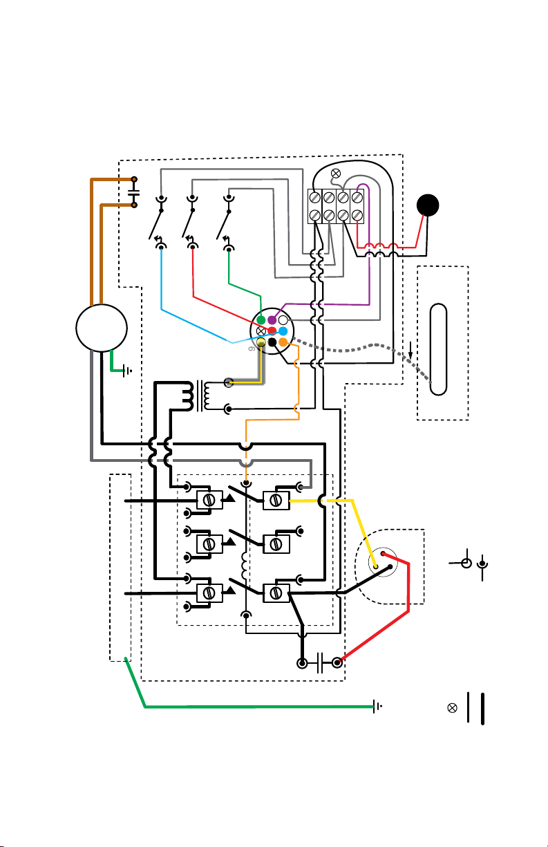
Wiring Diagrams
TimerStat Pro 220 volt-1 ph-50/60Hz (3 Pole)
BROWN
220V 1PH FAN MTR
FAN
WHITE
BROWN
FAN RUN CAP
MOTOR
TRANSFORMER
BLACK
L1 L2
JUNCTION BOX
SWITCH
LOW PRESS.
240/ 24v
SWITCH
FLOW SWITCH
HIGH PRESS.
BLUE
BLACK
WHITE
RED
TOP
GREEN
312
6
9
WHITE
WHITE
8
Yellow
24V COIL
WHITE
4
7
Orange
Black
Orange
Black
BLACK
CONTACTOR
ground
60 Hz = HP Series 50 Hz = HP50 Series
Power Supply 208/240v 1 ph 50/60 Hz
CONTROL BOX
GREEN
RUN CAP
Purple
White
Yellow
C1
R3
Red
Black
WIRES TO PLUG
9-PIN PLUG/
RECEPTACLE
S2
Ground to
Evap Flange
& Grounding
PN 5L621
REVISED 6-10-18
Water Temp Sensor
TimerStat PRO
DIGITAL POCKET
.25 QUICK CONNECT
.187 QUICK CONNECT
COMPRESSOR
24V WIRING
Lug
HIGH Voltage WIRING
NO CONNECTION
Appendix A-53

Wiring Diagrams
TimerStat Pro 220 volt-3 ph-60Hz
BROWN
220V 1PH FAN MTR
FAN
WHITE
JUNCTION BOX
BROWN
MOTOR
BLACK
L3L1 L2
FAN RUN CAP
SWITCH
SWITCH
HIGH PRESS.
LOW PRESS.
BLUE
240/ 24v
TRANSFORMER
BLACK
WHITE
FLOW SWITCH
GREEN
312
RED
6
9
TOP
24V COIL
WHITE
8
Yellow
WHITE
WHITE
4
7
Orange
Orange
Black
Red
Black
Black
Purple
Black
White
9-PIN PLUG/
RECEPTACLE
Yellow
S2
C1
R3
Water Temp Sensor
WIRES TO PLUG
TimerStat PRO
COMPRESSOR
PN 5L623
REVISED 6-10-18
DIGITAL POCKET
.25 QUICK CONNECT
.187 QUICK CONNECT
ground
Power Supply 220v 3 ph 60Hz ONLY - HP3 Series
CONTACTOR
CONTROL BOX
GREEN
Appendix A-54
Lug
Ground to
Evap Flange
& Grounding
24V WIRING
HIGH Voltage WIRING
NO CONNECTION

Wiring Diagrams
TimerStat Pro 380 volt-3 ph-50Hz
BROWN
220V 1PH FAN MTR
FAN
WHITE
BROWN
FAN RUN CAP
MOTOR
TRANSFORMER
BLACK
L1 L2
JUNCTION BOX
SWITCH
LOW PRESS.
BLUE
240/ 24v
SWITCH
FLOW SWITCH
HIGH PRESS.
BLACK
WHITE
RED
TOP
GREEN
312
6
9
Yellow
24V COIL
WHITE
WHITE
8
WHITE
4
7
Orange
Orange
Black
Black
BLACK
Purple
White
Yellow
C1
R3
Black
WIRES TO PLUG
9-PIN PLUG/
RECEPTACLE
S2
PN 5L620
REVISED 6-10-18
Water Temp Sensor
TimerStat PRO
DIGITAL POCKET
.25 QUICK CONNECT
.187 QUICK CONNECT
COMPRESSOR
CONTACTOR
ground
60 Hz = HP Series 50 Hz = HP50 Series
CONTROL BOX
RUN CAP
Power Supply 208/240v 1 ph 50/60 Hz
GREEN
Appendix A-55
Red
Lug
Ground to
Evap Flange
& Grounding
24V WIRING
HIGH Voltage WIRING
NO CONNECTION

Wiring Diagrams
TimerStat Pro 440 volt-3 ph-60Hz
BROWN
440V 1PH FAN MTR
FAN
WHITE
JUNCTION BOX
BROWN
MOTOR
BLACK
L3L1 L2
FAN RUN CAP
SWITCH
SWITCH
HIGH PRESS.
LOW PRESS.
BLUE
440/ 24v
TRANSFORMER
BLACK
WHITE
FLOW SWITCH
GREEN
312
RED
6
9
TOP
24V COIL
WHITE
8
Yellow
WHITE
WHITE
4
7
Orange
Orange
Black
Red
Black
Black
Purple
Black
White
9-PIN PLUG/
RECEPTACLE
Yellow
S2
C1
R3
Water Temp Sensor
WIRES TO PLUG
TimerStat PRO
COMPRESSOR
PN 5L624
REVISED 6-10-18
DIGITAL POCKET
.25 QUICK CONNECT
.187 QUICK CONNECT
ground
Power Supply 440v 3 ph 60Hz ONLY - HP4 Series
CONTACTOR
CONTROL BOX
GREEN
Appendix A-56
Lug
Ground to
Evap Flange
& Grounding
24V WIRING
HIGH Voltage WIRING
NO CONNECTION

Wiring Diagrams
Digital Model Wiring Diagrams
Digital 220 volt-1 ph-50/60Hz (2 Pole)
BROWN
FAN
MOTOR
220V 1PH FAN MTR
WHITE
JUNCTION BOX
ground + 2 wire 220v
BROWN
FAN RUN CAP
TRANSFORMER
BLACK
L1 L2
LOW PRESS. SWITCH
BLUE
240/ 24v
WHITE
RED
WHITE
TOP
WHITE
GREEN
HIGH PRESS. SWITCH
312
6
9
Orange
CONTACTOR
FLOW SWITCH
WHITE
4
8
7
7
YELLOW
Orange
WHITE
24V COIL
BLACK
Yellow
BLACK
BLACK
BLACK
Purple
CONTROL BOX
C1
Red
White
Black
VALVE
REVERSING
S2
R3
Sensor
PN 5L631
Water Temp
WIRES TO PLUG
9-PIN Connector Plug
PLAYER PLUS Board
DIGITAL POCKET
(Heat/Cool Only)
.25 QUICK CONNECT
.187 QUICK CONNECT
COMPRESSOR
REVISED 6-10-18
RUN CAP
Power Supply 208/240v 1 ph 50/60 Hz
GREEN
Appendix A-57
Lug
Ground to
Evap Flange
& Grounding
24V WIRING
HIGH Voltage WIRING
NO CONNECTION

Wiring Diagrams
Digital 220 volt-1 ph-50/60Hz-(3 Pole)
BROWN
FAN
220V 1PH FAN MTR
WHITE
ground + 3 phase
BROWN
FAN RUN CAP
MOTOR
208/220v/24v
TRANSFORMER
BLACK
L2
L3 L1
JUNCTION BOX
LOW PRESS. SW.
BLUE
TOP
WHITE
HIGH PRESS. SW.
RED
WHITE
WHITE
WHITE
GREEN
3
9
24V COIL
WHITE
2
8
YELLOW
Orange
FLOW SWITCH
CONTACTOR
1
7
BLACK
Yellow
Red
Black
BLACK
BLACK
Purple
White
CONTROL BOX
C1
Black
9-PIN Connector Plug
VALVE
REVERSING
(Heat/Cool Only)
S2
R3
Sensor
PN 5L660
Water Temp
WIRES TO PLUG
REVISED 7-17-17
PLAYER PLUS Board
DIGITAL POCKET
.25 QUICK CONNECT
.187 QUICK CONNECT
COMPRESSOR
24V WIRING
HIGH Voltage WIRING
NO CONNECTION
Power Supply 208/220v 3 ph 60Hz ONLY
GREEN
Ground to
Evap Flange
& Grounding
Lug
Appendix A-58

Wiring Diagrams
Digital 220 volt-3 ph-60Hz
BROWN
FAN
220V 1PH FAN MTR
WHITE
ground + 3 phase
BROWN
FAN RUN CAP
MOTOR
208/220v/24v
TRANSFORMER
BLACK
L2
L3 L1
JUNCTION BOX
LOW PRESS. SW.
BLUE
TOP
WHITE
HIGH PRESS. SW.
RED
WHITE
WHITE
WHITE
GREEN
3
9
24V COIL
WHITE
2
8
YELLOW
Orange
FLOW SWITCH
CONTACTOR
1
7
BLACK
Yellow
Red
Black
BLACK
BLACK
Purple
White
CONTROL BOX
C1
Black
9-PIN Connector Plug
VALVE
REVERSING
(Heat/Cool Only)
S2
R3
Sensor
PN 5L660
Water Temp
WIRES TO PLUG
REVISED 7-17-17
PLAYER PLUS Board
DIGITAL POCKET
.25 QUICK CONNECT
.187 QUICK CONNECT
COMPRESSOR
24V WIRING
HIGH Voltage WIRING
NO CONNECTION
Power Supply 208/220v 3 ph 60Hz ONLY
GREEN
Ground to
Evap Flange
& Grounding
Lug
Appendix A-59

Wiring Diagrams
Digital 380 volt-3 ph-50Hz
BROWN
BROWN
FAN RUN CAP
FAN
MOTOR
220V 1PH FAN MTR
WHITE
ground + 3 phase + nuetral
TRANSFORMER
BLACK
L2
L3 L1
JUNCTION BOX
LOW PRESS. SW.
240/ 24v
WHITE
BLUE
TOP
WHITE
RED
HIGH PRESS. SW.
WHITE
FLOW SW.
CONTACTOR
WHITE
GREEN
3
9
24V COIL
WHITE
WHITE
1
2
7
8
YELLOW
BLACK
Orange
Red
BLACK
Yellow
Black
BLACK
Purple
CONTROL BOX
C1
Black
White
(Heat/Cool Only)
REVERSING VALVE
S2
R3
Sensor
PN 5L670
Water Temp
WIRES TO PLUG
9-PIN Connector Plug
PLAYER PLUS Board
DIGITAL POCKET
.25 QUICK CONNECT
.187 QUICK CONNECT
COMPRESSOR
REVISED 7-17-17
24V WIRING
HIGH Voltage WIRING
NO CONNECTION
Power Supply 380v 3 ph 50Hz ONLY
GREEN
Ground to
Evap Flange
& Grounding
Lug
Appendix A-60

Wiring Diagrams
Digital 440 volt-3 ph-60Hz
BROWN
FAN
440V 1PH FAN MTR
WHITE
ground + 3 phase
BROWN
FAN RUN CAP
MOTOR
TRANSFORMER
BLACK
L2
L3 L1
JUNCTION BOX
SWITCH
LOW PRESS.
HIGH PRESS. SWITCH
BLUE
240/ 24v
TOP
WHITE
RED
WHITE
WHITE
WHITE
GREEN
3
9
24V COIL
WHITE
1
2
8
YELLOW
Orange
FLOW SWITCH
CONTACTOR
7
BLACK
Yellow
Red
BLACK
BLACK
Black
Purple
White
CONTROL BOX
C1
Black
9-PIN Connector Plug
VALVE
REVERSING
(Heat/Cool Only)
S2
R3
Sensor
PN 5L637
Water Temp
WIRES TO PLUG
REVISED 6-10-18
PLAYER PLUS Board
DIGITAL POCKET
.25 QUICK CONNECT
.187 QUICK CONNECT
COMPRESSOR
24V WIRING
HIGH Voltage WIRING
NO CONNECTION
Power Supply 440v 3 ph 60Hz ONLY
GREEN
Ground to
Evap Flange
& Grounding
Lug
Appendix A-61

Specification by Model
Appendix B
Specications by Model
Heat Siphon Compressor Mfr Power Supply Req'd @60 Hz @50 Hz Run Wire Breaker Lbs
Model No. Model Number Voltage HZ PH BTUh-COP BTUh-COP Cap. MCA Amps R410A LRA
Classic "C" Series (TimerStat Pro Equipped)
C200HP Heating Only Models
C200HP ZP25K5E-PFV 208-230 60 1 45K - 5.6 NA - NA 40/370 19.8 30 3.10 73
C200HP50 ZP25K5E-PFJ 220-240 50 1 NA - NA 37K - 5.6 40/370 16.1 25 3.10 60
C200HPX ZP25K5E-TFD 380-440 50/60 3 45K - 5.6 37K - 5.6 NA/NA 7.0 15 3.10 28
C250HP Heating Only Models
C250HP ZP31K5E-PFV 208-230 60 1 52.4K - 5.01 NA - NA 45/370 25.4 30 3.35 79
C250HP50 ZP31K5E-PFJ 220-240 50 1 NA - NA 43.7K - 5.01 60/370 20.9 30 3.35 67
C250HPX ZP31K5E-TFD 380/440 50/60 3 50K - 6.20 42K - 6.25 NA 9.7 10 3.35 38
C375HP Heating Only Models
C375HP ZP54K5E-PFV 208-230 60 1 89K - 6.24 74.2K - 6.24 80/440 38.7 40 5.85 140
C375HP50 ZP54K5E-PFJ 220-240 50 1 NA - NA 74.2K - 624 80/440 30.2 40 5.85 128
C375HPX ZP54K5E-TFD 380/440 50/60 1 89K - 6.24 74.2K - 6.24 NA 12.9 20 5.85 51.5
C575HP Heating Only Models
C575HP ZP70KWE-PFV 208-230 60 1 117.5K - 6.20 NA - NA 80/440 46.7 50 6.75 148
C575HP50 ZP70KWE-PFJ 220-240 50 1 NA - NA 97.8K - 6.20 80/440 43.2 50 6.75 176
C575HP3 ZP72KCE-TF5 208-230 60 3 120.8K - 6.20 NA - NA NA 34.5 40 6.75 164
C575HP4 ZP72KCE-TFD 414-506 60 3 120.8K - 6.20 NA - NA NA 17.7 20 6.75 75
C575HPX ZP72KCE-TFD 380/440 50/60 3 120.8K - 6.20 97.8K - 6.20 NA 17.7 20 6.75 134
Digital "Z" Series (Player Equipped)
Z200HP Heating Only Model
Z200HP ZP25K5E-PFV 208-230 60 1 45K - 5.6 NA - NA 40/370 19.8 30 3.10 73
Z200HP50 ZP25K5E-PFJ 220-240 50 1 NA - NA 37K - 5.6 40/370 16.1 25 3.10 60
Z200HPX ZP25K5E-TFD 380-440 50/60 3 45K - 5.6 37K - 5.6 NA/NA 7.0 15 3.10 28
Z250HP Heating Only Models
Z250HP ZP31K5E-PFV 208-230 60 1 52.4K - 5.01 NA - NA 45/370 25.4 30 3.35 79
Z250HP50 ZP31K5E-PFJ 220-240 50 1 NA - NA 43.7K - 5.01 60/370 20.9 30 3.35 67
Z250HPX ZP31K5E-TFD 380/440 50/60 3 50K - 6.20 42K - 6.25 NA 9.7 10 3.35 38
Z350HP Heating Only Models
Z350HP ZP49K5E-PFV 208-230 60 1 78K - 6.1 NA - NA 70/370 33.4 40 4.5 134
Z375HP Heating Only Models
Z375HP ZP54K5E-PFV 208-230 60 1 89K - 6.24 74.2K - 6.24 80/440 38.7 40 5.85 140
Z375HP50 ZP54K5E-PFJ 220-240 50 1 NA - NA 74.2K - 624 80/440 30.2 40 5.85 128
Z375HPX ZP54K5E-TFD 380/440 50/60 1 89K - 6.24 74.2K - 6.24 NA 12.9 20 5.85 51.5
Z575HP Heating Only Models
Z575HP ZP70KWE-PFV 208-230 60 1 117.5K - 6.20 NA - NA 80/440 46.7 50 6.75 148
Z575HP50 ZP70KWE-PFJ 220-240 50 1 NA - NA 97.8K - 6.20 80/440 43.2 50 6.75 176
Appendix B-62

Specification by Model
Heat Siphon Compressor Mfr Power Supply Req'd @60 Hz @50 Hz Run Wire Breaker Lbs
Model No. Model Number Voltage HZ PH BTUh-COP BTUh-COP Cap. MCA Amps R410A LRA
Z575HP3 ZP72KCE-TF5 208-230 60 3 120.8K - 6.20 NA - NA NA 34.5 40 6.75 164
Z575HP4 ZP72KCE-TFD 414-506 60 3 120.8K - 6.20 NA - NA NA 17.7 20 6.75 75
Z575HPX ZP72KCE-TFD 380/440 50/60 3 120.8K - 6.20 97.8K - 6.20 NA 17.7 20 6.75 134
Z700HP Heating Only Models
Z700HP ZP83KWE-PFV 208-230 60 1 135K - 6.0 NA - NA 80/440 46.7 50 8.5 185
Z700HP3 ZP83KCE-TF5 208-230 60 3 135K - 6.0 NA - NA NA 37.0 40 8.5 164
Z700HP4 ZP83KCE-TFD 414-506 60 3 135K - 6.0 NA - NA NA 19.1 20 8.5 100
Z700HPX ZP83KCE-TFD 380/440 50/60 3 135K - 6.0 112K - 6.0 NA 19.1 20 8.5 101
Z575HC HEAT-COOL Models
Z575HC ZP70KWE-PFV 208-230 60 1 115K - 6.14 NA - NA 80/440 46.7 50 9.2 148
Z575HC50 ZP70KWE-PFJ 220-240 50 1 NA - NA 97.8K - 6.20 80/440 43.2 50 9.2 176
Z575HC3 ZP72KCE-TF5 208-230 60 3 115k - 6.14 NA - NA NA 34.5 40 9.2 164
Z575HCX ZP72KCE-TFD 380/440 50/60 3 115K - 6.14 96K - 6.14 NA 17.7 20 9.2 134
Z575CP COOLING ONLY Models
Z575CP ZP70KWE-PFV 208-230 60 1 98K - NA NA - NA 80/440 46.7 50 6.75 148
Z575CP3 ZP72KCE-TF5 208-230 60 3 98K - NA NA - NA NA 34.5 40 6.75 164
Z575CP4 ZP72KCE-TFD 414-506 60 3 98K - NA NA - NA NA 17.7 20 6.75 75
Z575CPX ZP72KCE-TFD 380/440 50/60 3 98K - NA 82KK - NA NA 17.7 20 6.75 134
Classic "CF" Flow Sensing Series
(TimerStat Pro Equipped) - Fall 2020
CF200HP Heating Only Models
CF200HP ZP25K5E-PFV 208-230 60 1 45K - 5.6 NA - NA 40/370 19.8 30 3.10 73
CF200HP50 ZP25K5E-PFJ 220-240 50 1 NA - NA 37K - 5.6 40/370 16.1 25 3.10 60
CF200HPX ZP25K5E-TFD 380-440 50/60 3 45K - 5.6 37K - 5.6 NA/NA 7.0 15 3.10 28
CF250HP Heating Only Models
CF250HP ZP31K5E-PFV 208-230 60 1 52.4K - 5.01 NA - NA 45/370 25.4 30 3.35 79
CF250HP50 ZP31K5E-PFJ 220-240 50 1 NA - NA 43.7K - 5.01 60/370 20.9 30 3.35 67
CF250HPX ZP31K5E-TFD 380/440 50/60 3 50K - 6.20 42K - 6.25 NA 9.7 10 3.35 38
CF375HP Heating Only Models
CF375HP ZP54K5E-PFV 208-230 60 1 89K - 6.24 74.2K - 6.24 80/440 38.7 40 5.85 140
CF375HP50 ZP54K5E-PFJ 220-240 50 1 NA - NA 74.2K - 624 80/440 30.2 40 5.85 128
CF375HPX ZP54K5E-TFD 380/440 50/60 1 89K - 6.24 74.2K - 6.24 NA 12.9 20 5.85 51.5
CF575HP Heating Only Models
CF575HP ZP70KWE-PFV 208-230 60 1 117.5K - 6.20 NA - NA 80/440 46.7 50 6.75 148
CF575HP50 ZP70KWE-PFJ 220-240 50 1 NA - NA 97.8K - 6.20 80/440 43.2 50 6.75 176
CF575HP3 ZP72KCE-TF5 208-230 60 3 120.8K - 6.20 NA - NA NA 34.5 40 6.75 164
CF575HP4 ZP72KCE-TFD 414-506 60 3 120.8K - 6.20 NA - NA NA 17.7 20 6.75 75
CF575HPX ZP72KCE-TFD 380/440 50/60 3 120.8K - 6.20 97.8K - 6.20 NA 17.7 20 6.75 134
Digital "ZF" Flow Sensing Series
(Player Pro Equipped) - Fall 2020
ZF200HP Heating Only Models
ZF200HP ZP25K5E-PFV 208-230 60 1 45K - 5.6 NA - NA 40/370 19.8 30 3.10 73
Appendix B-63

Specification by Model
Heat Siphon Compressor Mfr Power Supply Req'd @60 Hz @50 Hz Run Wire Breaker Lbs
Model No. Model Number Voltage HZ PH BTUh-COP BTUh-COP Cap. MCA Amps R410A LRA
ZF200HP50 ZP25K5E-PFJ 220-240 50 1 NA - NA 37K - 5.6 40/370 16.1 25 3.10 60
ZF200HPX ZP25K5E-TFD 380-440 50/60 3 45K - 5.6 37K - 5.6 NA/NA 7.0 15 3.10 28
ZF250HP Heating Only Models
ZF250HP ZP31K5E-PFV 208-230 60 1 52.4K - 5.01 NA - NA 45/370 25.4 30 3.35 79
ZF250HP50 ZP31K5E-PFJ 220-240 50 1 NA - NA 43.7K - 5.01 60/370 20.9 30 3.35 67
ZF250HPX ZP31K5E-TFD 380/440 50/60 3 50K - 6.20 42K - 6.25 NA 9.7 10 3.35 38
ZF375HP Heating Only Models
ZF375HP ZP54K5E-PFV 208-230 60 1 89K - 6.24 74.2K - 6.24 80/440 38.7 40 5.85 140
ZF375HP50 ZP54K5E-PFJ 220-240 50 1 NA - NA 74.2K - 624 80/440 30.2 40 5.85 128
ZF375HPX ZP54K5E-TFD 380/440 50/60 1 89K - 6.24 74.2K - 6.24 NA 12.9 20 5.85 51.5
ZF575HP Heating Only Models
ZF575HP ZP70KWE-PFV 208-230 60 1 117.5K - 6.20 NA - NA 80/440 46.7 50 6.75 148
ZF575HP50 ZP70KWE-PFJ 220-240 50 1 NA - NA 97.8K - 6.20 80/440 43.2 50 6.75 176
ZF575HP3 ZP72KCE-TF5 208-230 60 3 120.8K - 6.20 NA - NA NA 34.5 40 6.75 164
ZF575HP4 ZP72KCE-TFD 414-506 60 3 120.8K - 6.20 NA - NA NA 17.7 20 6.75 75
ZF575HPX ZP72KCE-TFD 380/440 50/60 3 120.8K - 6.20 97.8K - 6.20 NA 17.7 20 6.75 134
ZF700HP Heating Only Models
ZF700HP ZP83KWE-PFV 208-230 60 1 135K - 6.0 NA - NA 80/440 46.7 50 8.5 185
ZF700HP3 ZP83KCE-TF5 208-230 60 3 135K - 6.0 NA - NA NA 37.0 40 8.5 164
ZF700HP4 ZP83KCE-TFD 414-506 60 3 135K - 6.0 NA - NA NA 19.1 20 8.5 100
ZF700HPX ZP83KCE-TFD 380/440 50/60 3 135K - 6.0 112K - 6.0 NA 19.1 20 8.5 101
ZF575 HEAT-COOL Models
ZF575HC ZP70KWE-PFV 208-230 60 1 115K - 6.14 NA - NA 80/440 46.7 50 9.2 148
ZF575HC50 ZP70KWE-PFJ 220-240 50 1 NA - NA 97.8K - 6.20 80/440 43.2 50 9.2 176
ZF575HC3 ZP72KCE-TF5 208-230 60 3 115k - 6.14 NA - NA NA 34.5 40 9.2 164
ZF575HCX ZP72KCE-TFD 380/440 50/60 3 115K - 6.14 96K - 6.14 NA 17.7 20 9.2 134
ZF575 COOLING ONLY Models
ZF575CP ZP70KWE-PFV 208-230 60 1 98K - NA NA - NA 80/440 46.7 50 6.75 148
ZF575CP3 ZP72KCE-TF5 208-230 60 3 98K - NA NA - NA NA 34.5 40 6.75 164
ZF575CP4 ZP72KCE-TFD 414-506 60 3 98K - NA NA - NA NA 17.7 20 6.75 75
ZF575CPX ZP72KCE-TFD 380/440 50/60 3 98K - NA 82KK - NA NA 17.7 20 6.75 134
Appendix B-64

Heat Siphon® Accessories
The following accessories are available for your Heat Siphon"- for details visit our website www.HEATSIPHON.com or
call the factory
1.1 Hardwired Add-Ons
Hardwired Add-Ons allow Heat Siphon to provide pump override, Pump timer control, and enable
use of Heat Siphon with 3rd party controllers:
1.1.1 EasyPic
A daughter board plug in which provides screw down connections for pool spa combo owners so they can use 3rd
party controllers to switch between Heat Siphons pool and spa set points as well as turning Heat Siphon on and o
1.1.2 EasyClock
An EasyPic card with a real time clock - which allows you to use your Player as a pool pump time clock which can turn
the pool pump o and on twice a day . Requires a T-Pod or S-Pod to operate.
1.1.3 J-Pod
Provides Using software and hardware ALREADY BUILT INTO your DIGITAL HEAT SIPHON’s PLAYER CONTROL BOARD, your
J-POD Accessory Kit adds PUMPJUMP™ o c ycle heating to maintain your pool at temperature 24 hours/day - 7 days/
week - EVEN WHEN YOUR POOL PUMP TIME CLOCK HAS THE PUMP OFF.
Appendix C
Accessories Available
J-POD is designed to enable the “PumpJump™” feature built into your Heat Siphon Player Control to ensure that your
pool temperature will be maintained even when you scheduled your pump to be o. It does this by turning your pool
pump on every 30 minutes and briey running it long enough to clear the plumbing lines and check the temperature. If
the water is still warm, the pump is shut o. If the pool water is more than 1.5° F below set-point, the pool pump will
continue to run and your Heat Siphon will turn on and run until the pool reaches temperature. Then both Heat Siphon
and pump will shut o. override so you can maintain your pool at temperature even if the pool pump timer is o .
1.1.4 T-Po d
Using software and hardware ALREADY BUILT INTO DIGITAL HEAT SIPHON’s PLAYER CONTROL BOARD, your T-POD
Accessory Kit minimizes your pump operating cost by providing a one-event-per-day pump timer with o cycle heating
(PumpJump™) to maintain your pool at temperature 24 hours/day - 7 days/week. T-POD is designed to let you control
your pool or spa pump’s daily start-up and run times in 6 minute increments from ALWAYS OFF to 24 hrs ON. It does
this using just the TWO(2) buttons on your Digital Heat Siphon Player. Once it is successfully installed your Digital Heat
Siphon Player will automatically turn your pump on and o in the background. - used in conjunc tion with and requires
an EasyClock card to work
Appendix C-65

Heat Siphon® Accessories
1.2 Wireless Add-Ons
1.2.1 Coach Wireless Controller
The Wireless Heat Siphon Coach® System is an FCC approved wireless commercial swimming pool controller designed
to work with all Digital Heat Siphon® Swimming Pool Heat Pumps. It monitors and controls all Heat Siphons in the
system while providing load management and reporting the operating status to the pool manager on the Heat Siphon
Coach® console.
It controls the temperature and schedules on and o times for up to 24 individual Heat Siphons in up to three "banks"
or groups. Each Bank must be plumbed into and dedicated to one body of water (main pool, kiddie pool wading pool
etc.). The Heat Siphon Coach® Control System will accommodate one or three bodies of water, each with its own pool
water temperature set point.
In addition to controlling multiple Heat Siphons heating up to three pools, it also is capable of controlling scheduling
and up to three Auxiliary Pool Operating Devices or A-PODs, each of which can turn on or o, a single pha se inductive
or resistance load up to 2 horsepower.
1.2.2 Football Wireless Controller
For pool spa combo multiple Heat Siphon control using wireless PassPort and portable plugin Football Controller.
1.3 Other Accessories
1.3.1 Noise blankets
to reduce compressor noise
Appendix C-66

SPA / HOT TUB Heating Issues
Appendix D
SPA / HOT TUB Heating Issues
WARNING! Water Temperature Safety
Failure to heed the following may result in permanent injury or death.
Prolonged immersion in water warmer than normal body temperature may cause a condition known as HYPERTHERMIA. The symptoms of hyperthermia include: unawareness of impending hazard,
failure to perceive heat, failure to recognize the need to exit the spa,
and unconsciousness. The use of alcohol, drugs, or medication can
greatly increase the risk of fatal hyperthermia. In addition, persons
having an adverse medical history, or pregnant women, should
consult a physician before using a hot tub or spa. Children and the
extreme elderly should be supervised by a responsible adult.
Here are few RULES posted by Home Owners & Condominium Associations across the country which should be
followed by everyone who owns or uses a Spa or Hot Tub:
1. Do not use, or allow the hot tub to be used, alone.
2. Persons suering from heart disease, high blood pressure, diabetes, or other health problems should
not enter the spa without prior medical consultation and permission from your doctor
3. Do not permit children under the age of eighteen (18) to use the hot tub unless they are closely
supervised at all times.
4. Unsupervised use by children is strictly prohibited. In no case should children under the age of eight
(8) be permitted in the hot tub. Never leave children unattended in the vicinity of the hot tub.
5. Pregnant women and individuals under medical care (for such problems as heart disease, diabetes,
high blood pressure, skin sensitivities, cardiac or circulatory problems) should consult their physician
prior to using the hot tub.
6. Never use the hot tub when taking anticoagulants, antihistamines, vasoconstrictors, vasodilators,
stimulants, narcotics or tranquilizers. In all cases, if you are not thoroughly familiar with the medication(s)
that you are taking, please consult with your physician prior to using the hot tub.
7. Soaking for too long at high water temperatures can elevate body temperature and the temperature
of internal organs beyond safe limits. Observe reasonable time limits to avoid nausea, dizziness and
fainting. Should you experience any of these symptoms, carefully exit the hot tub immediately.
8. Alcoholic beverages should not be consumed before or during hot tub use. The temperature of the
water may intensify the eects of alcohol and cause drowsiness, dizziness and/or unconsciousness.
Appendix D-67

SPA / HOT TUB Heating Issues
9. Always use caution when entering and exiting the hot tub. Wet surfaces can be slippery.
The following guidance is found on the Consumer Product Safety Commission website:
10. Before entering the hot tub, users should check the water temperature with an accurate thermometer;
hot tub thermostats may err in regulating water temperatures by as much as four degrees.
11. Hot tub water temperatures should never exceed 104 degrees Fahrenheit. A temperature of 100
degrees is considered safe for a healthy adult. Special caution is suggested for young children.
12. Excessive drinking during hot tub use can cause drowsiness which could lead to unconsciousness and
subsequently result in drowning.
13. Pregnant women beware! Soaking in water above 102 degrees Fahrenheit can cause fetal damage
during the rst three months of pregnancy (resulting in the birth of a brain damaged or deformed child).
Pregnant women should stick to the 100-degree maximum rule.
14. Persons with medical history of heart disease, circulatory problems, diabetes or blood pressure
problems should obtain their physician's advice before using hot tubs.
15. Persons taking medications which induce drowsiness, such as tranquilizers, anti-histamines or
anti-coagulants, should not use hot tub
Thermostat Set Point Depression
WARNING - To avoid Thermostat Set point Depression, which could
lead to an unsafe spa temperature, INSULATE THE PIPING IF AT ALL
POSSIBLE TO AND FROM THE SPA AND OPERATE THE PUMP AT HIGH
SPEED WHEN HEATING YOUR SPA.
Following all local electrical codes restricting placement in proximity to the pool or spa as well as the use of ground fault circuit
breakers, bonding and other wiring requirements, locate your Heat
Siphon as close as SAFELY possible to the Spa.
In addition to all of the installation requirements found in the Heat Siphon Owners Manual for pools and pool/
spa combo’s, the following important issues must be addressed when installing and operating a Spa or Hot Tub.
Most Spas which are heated separately or as "stand alone" spas using a Heat Siphon or other Spa Heaters especially
fossil fuel types tend to be located out of sight of the spa to prevent bathers from tampering with the thermostat as
well as to keep the public away from hot surfaces and fumes.
In many cases the heater is 15 to 25 feet away and more from the Spa, and most have the pipes buried at least
a foot or more under ground.
In these cases, the hot water leaving the spa to be reheated, must travel inside pipes surrounded by sand, clay or
Appendix D-68

SPA / HOT TUB Heating Issues
Heater Thermostat
Water Temp
Sensor
FILTER
PUMP
SPA Inlet °F = Heater Outlet °F - Ground Heat Loss
SPA Outlet °F - Ground & Equipment Heat Loss = Heater Inlet °F
Heater Inlet °F + ° F Rise = Heater Outlet °F
SPA °F = Mixed SPA °F
(Inlet + Main Spa Bulk Water)
Average of Skimmer + Main Drain
Equipment
Heat Loss
BURIED PIPING = GROUND HEAT LOSS
SPA TEMPERATURE will ALWAYS be HIGHER than the HEATER SETPOINT
because of Ground Heat Loss & Equipment Heat Loss
Spa/Hot Tub Thermostat Setpoint Depression
even wet soil which will be 20 to 30°F or more below the spa water. By the time the water reaches the heaters inlet
it can be 5 to 10 °F colder than the spa. If this heat loss is excessive it may even prevent the heater from reaching
its set point altogether.
Virtually all pool and spa heaters' thermostat sensors are located at the inlet port of the heater. It is under control
of the manufacturer and is the safest secure place to measure the water temperature to determine if the water is still
below the set point of the heater's thermostat. If it is the heater continues to run.
The heaters outlet temperature or degree rise above the inlet temperature, depends on the heater's BTUH output
and the flow rate of the water going through it. The outlet water may be 5 to 10°F or more above the inlet temperature
and well above the heat loss it will undergo as it returns to the spa.
So even though the heater inlet temperature is below the actual spa temperature, the water temperature returning
to the spa can still be above the spa bulk water temperature.
Thus, all heaters will "overheat the water" by the same number of °F the water has lost (say X degrees) getting
to them, because they will keep heating until they reach the heater's set point.
As shown in the table, an 80,000 BTUH size heater with 15 GPM going thru it, will have a throughput degree
rise of 10.7°F (outlet minus inlet temperature).
If, for example, this heater's thermostat is set to 104°F and the water in the spa is 104°F and it loses 4°F in the
piping to the heater, it will be 100°F at the heater inlet and the heater will continue heating the water. The outlet
temperature will be 100°F plus 10.7° rise = 110.7°F and if it loses 4°F returning to the spa it will be 106.7°F when
it returns, mixing and raising the spa temperature even further.
The heater will continue to heat the water until the inlet temperature is 104°F and the return water just before
it shuts off will be 104°F plus 10.7°F rise minus 4 degree return loss = 110.7°F and the spa will reach 108°F or 4
degrees above the thermostat set point when it shuts off.
Appendix D-69

SPA / HOT TUB Heating Issues
So you can see where the statement made by the Consumer Product Safety Commission that " HOT TUB THERMOSTATS MAY ERR IN REGULATING WATER TEMPERATURES BY AS MUCH AS FOUR DEGREES" - is a case of
Thermostat Set Point Depression caused by excessive heat loss from long piping runs plus excessive heater degree
rise caused by low flow.
If the flow rate is tripled to 45 GPM then the degree rise is cut by 66% to 3.6°F (see table) and the heat loss will be
cut to 1.3°F in the piping because every gallon will spend 1/3 of the time exposed to the cold ground. The net result is
• Inlet temp = spa temp -1.3°F.
• Return temp = Inlet temp + 3.6°F rise -1.3°F loss =inlet temp+2.3°F
• At a 104°F set point the spa temp will be 105.3°F
Spa Temperature Sensor Calibration
As of Player software revision 1.253 (heating only models) and 1.309 (Heat/Cool models) Heat Siphon's DIGITAL
Z series Player Controller provides a way to calibrate the spa temperature sensor by increasing the inlet temperature reading to match the actual spa temperature. The temperature may be increased from 1 to 5°F in 1°F steps.
This will not eliminate the differential due to ground loss which only insulating the supply and return lines can
mitigate. High flow rates reduce ground loss and mix the spa return water better raising the bulk average spa water
temperature which in turn raises the heater inlet temp.
Call us or ask your installing dealer to perform this calibration
HOWEVER MAKE SURE YOU ALWAYS
• RUN THE PUMP ON THE SAME RPM/FLOW RATE WHEN HEATING AS YOU USED DURING CALIBRATION.
• ALWAYS RUN ON HIGHEST PUMP SPEED WHEN HEATING.
Appendix D-70

SPA / HOT TUB Heating Issues
Time vs Temperature Burn Data
Water Temperature
100 °F
105 °F
110 °F
115 °F
120 °F
125 °F
130 °F
135 °F
140 °F
145 °F
150 °F
Minutes Exposure
0 0.05 0.28 2 8 14 45 180 300
1st degree (no permanent damage) 2nd-3rd degree
Source: Report prepared by Dr. Moritz and Dr. Henriques at Harvard Medical School in the 1940s For adult males.
Spa Thermostat Set Points above 102°F
In the 1940s a study was conducted by two doctors at Harvard to determine the time versus temperature required
for a normal adult to suffer 1st and 2nd-3rd degree burns. The following graph shows their findings .
Although it is not conclusive for all people or at lower temperatures, it is clear that exposure above 110°F will
eventually cause burns after a given exposure time. As shown above, spa temperatures can and usually are above the
set point of the spa heater ESPECIALLY where long uninsulated piping separates the two and a lower flow rate is used.
The Consumer Product Safety Commission (CPSC) states that a Spa temperature of 100°F is considered safe
for a healthy adult. Pregnant women should avoid soaking in water above 102°F as it can cause fetal damage and
should stick to the 100°F maximum rule. Spa owners should take special precautions with children and the elderly.
Based on CPSC Guidelines it appears unnecessary or at least unwise to heat above 102°F,. and even though the
UL standard for spa heaters allows a maximum thermostat set point of 104°F , Heat Siphon has chosen to set the
default maximum spa set point temperature of 102°F.
If you still feel it is necessary to have a higher set point than Heat Siphon’s maximum default 102°F , then
your dealer can increase it in 1°F steps to 104°F, HOWEVER, YOU MUST ASSUME TOTAL RESPONSIBILITY FOR
OPERATING THE SPA AT THESE TEMPERATURES.
You must sign and return the hold harmless agreement on our website before we will authorize the dealer to
perform this change.
Appendix D-71

HEAT SIPHON
Recreational Water Heater
USA Limited Factory Warranty
IMPORTANT - Complete & Save For Your Records
Serial Number:
United States ThermoAmp Inc. warrants to the original owner that the Heat Siphon to be free of defects in material and workmanship for a period of two
(2) years from the date installed, except for the water side heat exchanger internal titanium which is warranted to be corrosion free for the LIFE OF THE
HEAT SIPHON REGARDLESS OF POOL WATER CHEMISTRY, and except for the compressor which is warranted for five (5) years PARTS AND
LABOR. This warranty does not include the repair of damage due to negligence, abuse, improper installation, use with in floor cleaning systems, improper
operation, environment, accident, failure to drain and winterize the heat exchanger, corrosion of any parts external to the heat exchanger or other
conditions beyond the normal intended use of the unit. This warranty does not include the furnishing of refrigerant or other expendable material. This
warranty is in lieu of all other warranties, expressed or implied, written or oral. This warranty applies only to Heat Siphons installed within the United
States of America. There are no implied warranties of merchantability of fitness for a particular purpose that apply to this product. United States Thermo-
Amp Inc. will replace or repair at its option, F.O.B. factory, freight prepaid, any of our parts that prove defective if such parts are returned to our plant,
freight prepaid, within the applicable warranty period specified herein. It is agreed that such replacement or repair is the exclusive remedy available from
United States ThermoAmp Inc. Unless authorized by United States ThermoAmp Inc. and performed by a Factory Authorized Service Center, United
States ThermoAmp Inc. is not liable for any labor involved in the removal of defective parts or the installation of replacement parts unless performed by a
factory authorized service center where available. United States ThermoAmp Inc. is not liable for any damages of any sort whatsoever, including incidental
and consequential damages. Parts returned under terms of this warranty will be repaired or replaced and returned transportation charges prepaid within
the United States by best and most economical means.
®
™
Model: ___________________ Date Installed: ______________
Installed By: ________________________________________
__________________________________________
W.P. Bernardi, President , United States ermoAmp Inc.
USA Warranty Certificate
72
 Loading...