

Page 1
OPERATING & SERVICE PARTS MANUAL
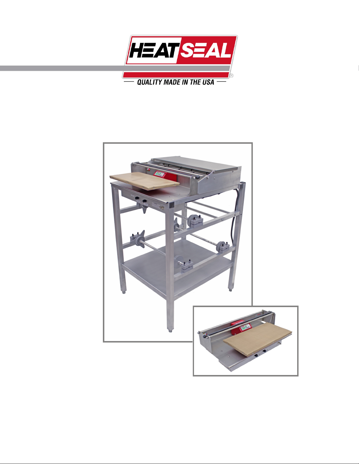
107ES & ESCK ENERGY SMART WRAPPER
MODEL 107-ES
MODEL 107-ESCK
READ ALL INSTRUCTIONS CAREFULLY BEFORE OPERATING EQUIPMENT
Revised 2013
Page 2

TABLE OF CONTENTS
Machine Components & Electrical Requirements ...................................................... 3
Preliminary Setup .......................................................................................................... 5
Attaching 107ESCK to 107A ......................................................................................... 5
Recommended Maintenance ........................................................................................ 8
Troubleshooting Guide ................................................................................................. 9
Hot Rod Circuit Board Test ......................................................................................... 10
Replacing Rocker Arm Assembly ............................................................................... 12
Service Parts Information ........................................................................................... 13
2
Revised 2013
Page 3
MACHINE TECHNOLOGY & COMPONENTS
ENERGY SMART TECHNOLOGY
The Energy Smart Wrapper is an innovative system that incorporates an “Instant On” heating foil with the ability to go
from ambient to sealing temperature in a matter of seconds. The high speed foil in combination with a load activated
switch allows the operator to seal a product on demand and to save energy when the wrapper is not in use. The first step
to getting the wrapper up and running is to set up the axle assembly and get the film mounted and threaded properly.
The special heating foil has been tested as part of our quality procedures and you may see a wavy or wrinkling affect on
the surface of the stainless steel plate just under the replaceable Non-stick cover. This waviness is caused by the differential thermal expansion of the materials that are used to construct the layered seal plate and wrinkling will be observed
as the wrapper is used daily and the seal plate settles in.
HOT ROD HEAT UP
With the film properly mounted and threaded, the wrapper is
ready to be powered up. See INSTALLING & REPLACING
AXLE ASSEMBLY.
After plugging the power cord into an electrical outlet, flip the
power switch located on the front of the electrical box to the
ON position.
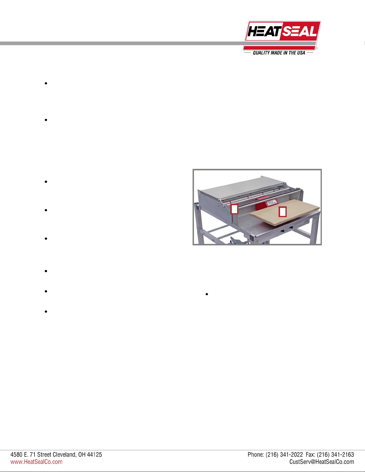
The hot rod (1) will require about a 5 minute warm up period
before it reaches a cutting temperature of above 275˚ F.
LOAD ACTIVATED HEATER
The seal plate of the wrapper is activated by a switch that is
engaged when a downward load is applied to the plate (2).
This feature ensures that the seal plate will consume energy
only when there is a demand by the operator.
Do NOT use the seal plate as a cutting surface, as this will
damage the thin heating foil and Non-stick cover plate. Seal
plate damage voids the warranty.
1
2
ELECTRICAL
REQUIREMENTS
The Model 625-ES requires 115 volts,
19 amps.
(20A breaker, GFCI protected circuit)
3
Revised 2013
Page 4
MACHINE TECHNOLOGY & COMPONENTS
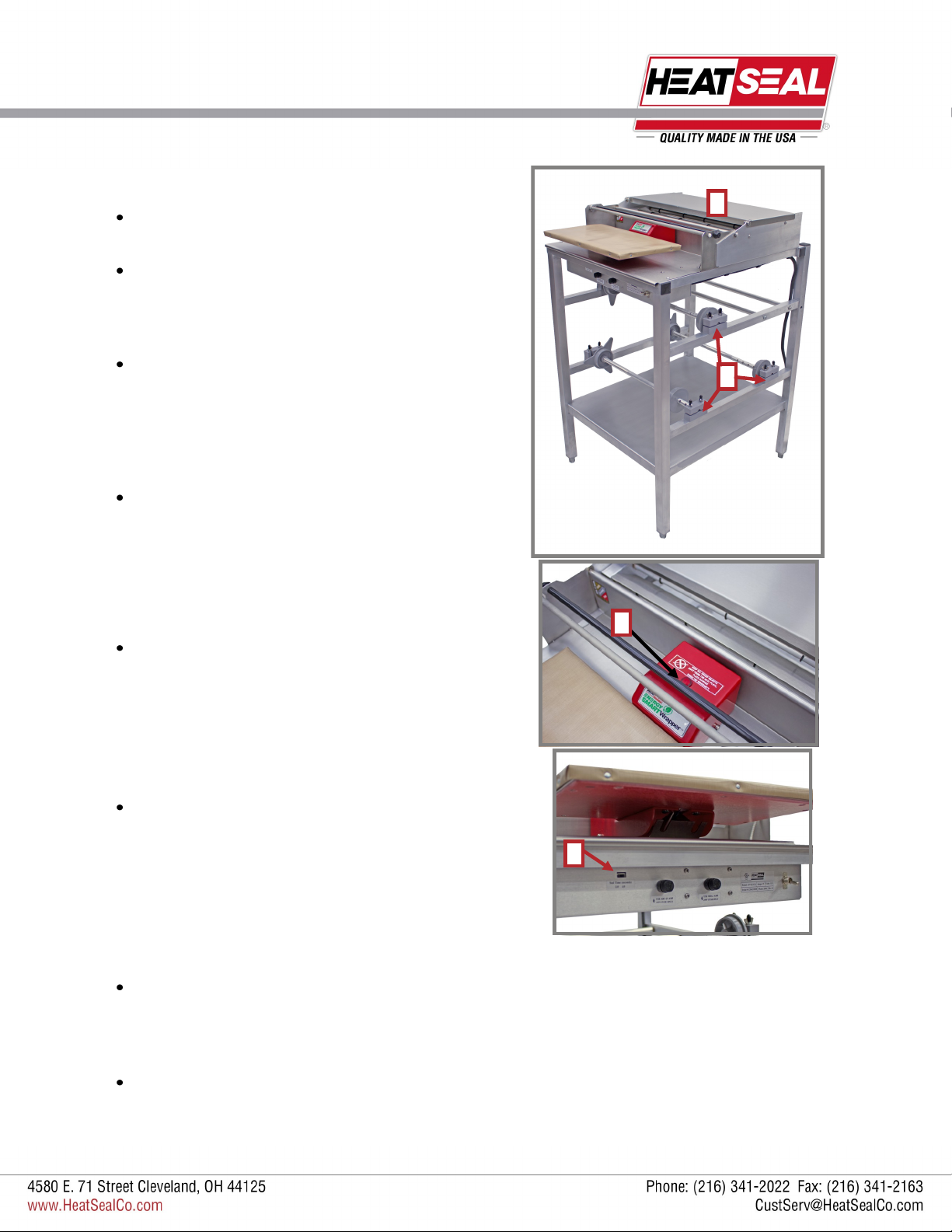
STAINLESS STEEL BRIDGE
The wrapper comes with a stainless steel bridge (1) that can
be utilized as a working surface while preparing products.
The stainless steel bridge is not recommended as a cutting
surface.
THREE ROLL CAPACITY
The wrapper has the ability to house three rolls of film at a
time (2). The rolls should be mounted and threaded as shown
on pages 6-7.
OPERATOR INDICATOR LIGHT
Since the sealing plate is only activated when a load is applied,
a red neon light (3) has been included to provide the operator a
visual indicator that the heater is active. When the light is on, the
seal plate switch is engaged and its surface will become hot
instantly.
TWO POSITION SWITCH
On the back of the electrical box, there is a two position switch
(4) which allows the operator to vary the length of time that the
seal plate is on. The 3.0 and 4.0 second settings allow for different film types being used. The 3.0 setting should be used to seal
most film types. However, you should test the seal ability of your
specific film material. The red neon light gives the operator a
visual time reference to these settings when sealing a product.
1
2
3
In order to maximize the energy savings of the wrapper, it is
suggested to use the lowest possible time setting that yields a
proper seal using the specific film selected for wrapping.
4
THERMISTOR TEMPERATURE CONTROL
Due to the rapid response of the heating foil and residual heat that can remain from previous cycles, a thermistor is incorporated as a temperature control device. The seal cycle can be shorter than 3 seconds when residual heat is present in seal
plate. The thermistor is located on the heating foil and it regulates the temperature of the seal plate to ensure that the foil
temperature peaks at around 300˚F.
NOTE: The thermistor is the governing control to supply heat to the seal plate over the timed indicator light. Therefore, if
residual heat is present in the seal plate, the sealing cycle can be shorter than the timed neon light. You should hear a brief
click when the foil reaches sealing temperature.
4
Revised 2013
Page 5
PRELIMINARY SETUP
HOW TO ATTACH 107-ESCK
CONVERSION KIT TO
107-A FRAME
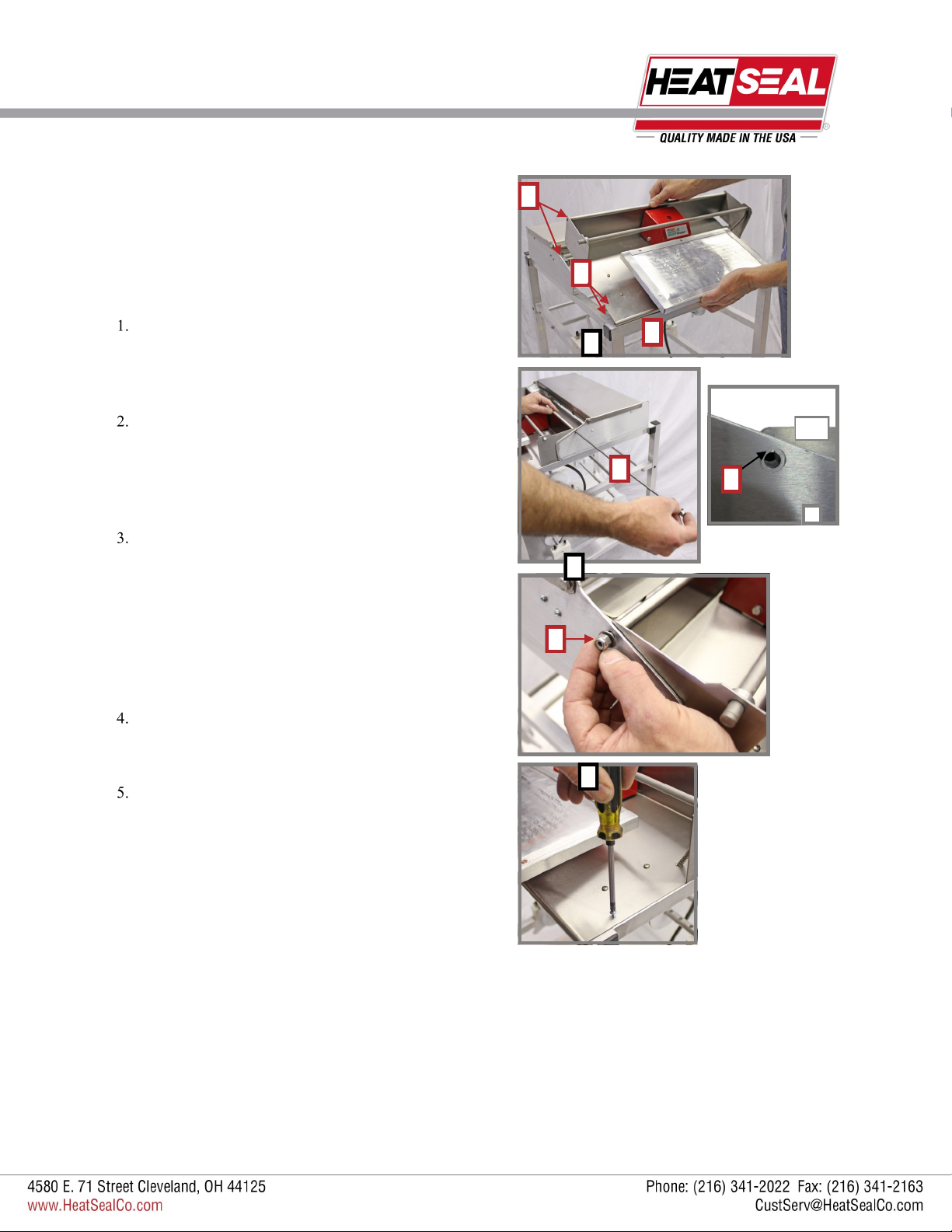
Detach the electrical line cord from 107-A frame. Then, remove
the old 107-A hot plate and front plate assembly from the 107-A
frame, by removing the support rod (A) and the two self tapping
screws that fix the base of the front plate assembly to the frame.
Angle the 107-ESCK conversion kit assembly forward, so that
the electrical box switches are positioned below the console bar
(B). Lower the back of the conversion kit into position, making
sure to line up the screw holes (C) and the support bar holes
(D).
With the nylock hex nut and washer on the rod, insert support
rod through the 107-A frame, side plate assembly, then through
the conversion kit and out the other side. Attach washer and
nylock hex nut (E) to the other end of support rod.
*For older 107-A models, you may have to widen the hole in
both outer aluminum side plates (F) that the support rod must
thread through in order to align all holes.
D
C
A
B
ESCK
F
*
2
3
E
Fasten the self taping screw through the conversion kit assembly and into the 107 aluminum frame. Repeat on the opposite
side.
Attach the electrical line cord to the 107 aluminum frame with
the line cord clamps and screws included with the ESCK unit.
4
Revised 2013
5
Page 6
PRELIMINARY SETUP
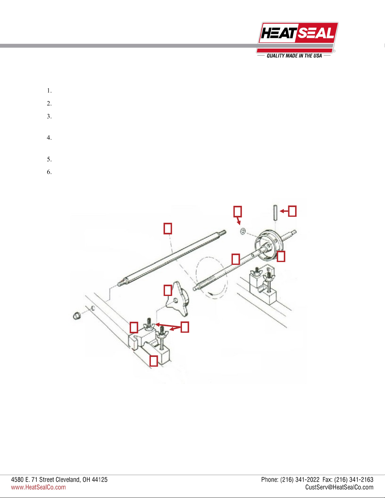
MOUNTING FILM ON AXLE
Loosen four wing nuts (A).
Swing out upper bearing blocks (B) on both sides.
Lift out axle assembly (C) and unscrew movable end cap (D), position fixed end cap (E) for correct film width then secure
with pin (F) and o-ring (G).
Position the cardboard core of the film roll against the taper of the fixed end cap. Make sure the film is threaded from the
bottom of the roll and under film roller (H) (see threading diagrams page 6)
Replace movable end cap (D) and screw on tightly.
Replace the axle assembly (C) and film roll onto the lower bearing blocks (I), swing upper bearing blocks (B) back into place
and tighten and adjust wing nuts (A) for desired film tension.
B
G
H
C
D
A
I
F
E
6
Revised 2013
Page 7

15”
15”
PRELIMINARY SETUP
THREADING THE FILM
Mount the film rolls onto axles (see page 7).
Pull film from the bottom of the roll up through the bottom of the
wrapper, starting with the nearest slot to the hot plate first. (A)
Drape unused film in the front of the roller (B).
B
MODEL 107-ES
FILM SELECTION
To change film to a different film width:
Lift up both handles (1).
Move evenly forward or backward (2) to desired film.
Lower into slots.
2
1
A
2
1
Revised 2013
7
Page 8

RECOMMENDED MAINTENANCE
* MAKE SURE TO TURN OFF THE UNIT, PULL THE PLUG
AND LET THE MACHINE COOL DOWN BEFORE CLEANING *
NON-STICK COVER & SEAL PLATE
Due to the advancement of this new technology, it is extremely important to maintain the Non-stick cover or seal plate protective cover in good condition. It is recommended to replace the Non-stick cover at least once every three months to protect the heating foil and maintain a sanitary surface. The seal plate should not be used as a cutting surface; any punctures
will render the seal plate ineffective and will void the warranty. The seal plate has been designed to provide long life performance when it is properly maintained.
The Non-stick cover is used to create a sanitary, stick free surface to seal film with the seal plate. Non-stick covers are porous, meaning liquids or moisture can permeate the cover, get to the surface of the seal plate, and burn off on the hot plate.
It’s recommended that the Non-stick cover be replace every three (3) months or as needed depending on the level of daily
wear and tear. The Non-stick cover should be changed if the surface is soiled, or holes, punctures, excessive wear, or damage are present.
The seal plate can be cleaned, as needed, with a mild spray degreaser, applied to a soft rag or paper towel and then wiped
on the plate while cold.
CUT OFF ROD
Make sure that the unit is turned off and the cut off rod is cold to the touch.
The film cut off rod can be cleaned, as needed. Cover the unit surfaces with paper towels to protect them from over spray
and debris.
Spray and coat the Cut-off Rod generously with an FDA approved “Degreaser” product.
After soaking for a few minutes, lightly scrub the surface of the Cut-off rod with a Scour Pad (Scotch-Brite™ type pad).
Wipe the surface clean of debris and residue with clean paper towels or cloths.
CLEANING THE UNIT
The 625ES can be completely wiped down using mild cleaning detergent and soft rags or paper towels. Do not hose down
or submerse the unit.
8
Revised 2013
Page 9

TROUBLESHOOTING
Symptom Possible Solution
No power to the
unit.
Seal Plate is working but the Red
Indicator Light is
not working properly.
Verify the unit is plugged into a 20 Amp, GFCI circuit and the Power Switch is set to the “ON” posi-
Is the GFCI circuit breaker tripped?
1) Remove “Non-Stick” Cover and inspect the Seal Plate for the following defects***:
Punctures or cuts.
Burn marks.
Extreme discoloration (blue/black or gold).
2) Ensure the GFCI circuit being utilized is not overloaded with other devices.
***If a surface defect is present, discontinue use of product and contact
Troy Roberts at: 800-342-6329 ext 276 or troberts@heatsealco.com
If the Red Indicator Light does not turn ON or OFF as expected, verify that the Red Indicator Light
Timer is functioning properly. Replace Timer Board Assembly as required (Part #1818-026).
Verify 120V is being supplied to the light when the Seal Plate is actuated. If voltage is present, replace the Rocker Arm Assembly Kit (Part #6340-076)
Figure 1
A
B
625ES Electrical Box Pictured
9
Revised 2013
Page 10

TROUBLESHOOTING
Symptom Possible Solution
Unit has power but
the Seal Plate does
not work
Does the Red Indicator Light turn ON when the unit is cycled?
1) If neither the Light nor Seal Plate work, verify that the 25 Amp fuse is good.
2) If the fuse is blown, verify there are no shorts to ground in the unit by checking wiring and
connections (see Figure 1).
3) Replace fuse as required (Part #1821-037).
Verify the Switch located in the Rocker Arm Assembly is functional.
1)Listen for an audible “click” of the Switch as the Seal Plate is pressed down.
Verify that the Pivot Bolts on the Rocker Housing are not too tight and that the Rocker
Housing rotates freely.
NOTE: The Pivot Bolts are installed with thread lock compound and tightened to leave a
0.015” gap between the bolt head and the Rocker Housing. If the bolts are removed this
process must be duplicated.
Verify that the bolts on the rear of the Rocker Housing that mount the switch are tight
and that the Switch is contacting the metal Base appropriately.
2) Verify switch wiring is intact by isolating the unit from power and using volt-ohm meter set to
measure resistance, measure between points A and B while cycling the Seal Plate. You
should see the circuit open and close as the Seal Plate is cycled up and down. (see Figure 1)
3) Replace Seal Plate & Rocker Arm Assembly or make repairs as required
(Seal Plate & Rocker Arm Kit - 625ES Part #6340-078; 107ES Part #6135-038;
Film Cut-off Rod
does not work at
all.
Verify the Timer Board is working properly. Upon actuation of the Seal Plate the sequence of events
should be as follows:
1) The Red Indicator Light should illuminate at the same time that the Seal Plate begins to get
hot.
2) The Seal Plate Timer should make an audible “click” and remove power from the Seal Plate
in 4 seconds or less (depending on the latent temperature of the Seal Plate).
3) The Red Indicator Light Timer should remove power from the Red Indicator Light after a
fixed time of either 3 or 4 seconds (depending on the Time Selection Switch setting).
If any of the previous steps do not occur, verify that the individual timers are seated properly to
the board. If the problem persists, replace the Timer Board Assembly (Part #1818-026).
Inspect and verify all wiring connections and condition of wires. (see Figure 1) Repair as required.
If the plate does not heat at all or is only slightly warm to the touch, replace the Seal Plate & Rocker
Arm Assembly (Seal Plate & Rocker Arm Kit - 625ES Part #6340-078; 107ES Part #6135-038).
Verify the unit is plugged into a 20 Amp, GFCI circuit and the Power Switch is set to the “ON” posi-
tion.
Verify that the 1 Amp fuse is good. If the fuse is blown, verify there are no shorts to ground in the
unit by checking wiring and connections. Replace fuse as required (Part #1821-034).
Clean Cut-off Rod surface and verify it is not bent. See “Cut-Off Rod” Maintenance. Film cuts too slowly
Replace Cut-off Rod Control Board (Part #1818-001)
Replace Cut-off Rod (Part #6340-062)
Revised 2013
10
Page 11

HOT ROD CIRCUIT BOARD TEST
HOT ROD CIRCUIT BOARD EXAMPLE
ELECTRICAL REQUIREMENTS
The Model 625-ES requires 115 volts, 19 amps.
(20A breaker, GFCI protected circuit)
For board location in machine see page 13, #2
HOT ROD CIRCUIT BOARD TEST
A standard 115 volt neon circuit tester can be used for these tests.
CHECKING 1 AMP FUSES
(The 1 Amp fuse is for the hot rod, while the 25 Amp fuse is for the seal plate)
Remove the fuses from their housing units located on the front of the electrical box. If a visual inspection does not verify a
blown fuse check for continuity by using the meter to read across the two terminals of the fuse.
If the meter reading does not show continuity, replace the fuse.
CHECKING THE HOT ROD
With the power turned OFF, remove the hot rod red wires from Terminals 1 and 2. Using the meter, measure the resistance
of the rod by connecting the leads of the meter to the red wires.
The meter should read between 130-136 ohms. If the reading is out of this range, replace the hot rod.
CHECKING THE THERMISTOR OF THE HOT ROD
With the power turned OFF, remove the hot rod black wires from Terminals 5 and 6. Using the meter, measure the resistance of the thermistor by connecting the leads of the meter to the black wires.
The resistance of the thermistor is heavily dependent on the temperature (higher temperature, lower resistance). At a room
temperature of 70˚ F, the reading should be in the range of 260-270 kΩ, 90˚ F yields about 230 kΩ, and 40˚ F yields about
340 kΩ.
If the reading at a given temperature is off by more than 50 kΩ or if an infinite resistance is recorded (an open circuit) the
thermistor is bad and the rod needs to be replaced.
CHECKING THE HOT ROD CIRCUIT BOARD
After the hot rod and both the fuses have passed the above testing procedures, the circuit board can be tested.
With all the wires shown in the example circuit board (above) properly connected and the power ON, use the meter to test
the voltage across Terminals 1 and 2. If there is no voltage being read, the board needs to be replaced.
11
Revised 2013
Page 12

REPLACING ROCKER ARM ASSEMBLY
Disassembling the Unit:
1. Turn off power and remove all power from machine and follow all local
safety procedures.
2. On the 107ES, remove rod that attaches the ES conversion kit from
the console legs, and two self tapping screws. Remove 4 pan head
Phillips screws that attached the electrical box. On 625ES, loosen
all four pan head Phillips screws, located at the top of the electrical
box - two in front, two in back, and remove the cover.
3. Unplug wires and remove wires from connections:
Remove the back six wires (labeled THERM 1 & 2, PEPI 1 & 2,
and LIGHT - & + on the board) from the green terminal connector block (A) on the large circuit board with a flat head screw
driver.
Remove all four screws holding the large circuit board (B).
Locate the three shiny black wires (C) coming from the rocker
arm and remove the wires from their connections. One connects to the bottom of the large circuit board and the other two
to slip on terminals for - all marked in picture 3.2 with blue
stickers.
Unscrew the green grounding wire (D) from the inside the box.
3.1
3.2
C
B
D
E
A
C
C
E
Separate the two wires being held by the wire nut (E).
4. Located under the machine, unscrew two hex head machine screws (F)
which connects the base stainless steel plate and rocker arm.
5. Pull the rocker arm assembly with wires out from the electrical box.
(If necessary, see page 2 Rocker Arm Parts Assembly)
Rewiring and Reassembling the Unit:
Reinstall rocker arm assembly in reverse order as on page 1.
Reconnect the wires (See page 3 for Timer Board close up):
Wire #7 should be matched with wire #7 from fuseholder and wire
nut together.
Wire #190 terminates to the top slot on front terminal board.
The two high luster wires—one goes to the neutral terminal board in
back and the other terminates under the large circuit board.
Non-terminal wires should be terminated into the green terminal
connector block (page 1 A) as follows:
- Thin black wire into “THERM 1 & 2”
- 22 gauge white wires into “PEPI 1 & 2”
- Wires #10 & #15 go into “LIGHT - & +”
5
625ES Shown
F
12
Revised 2013
Page 13

REPLACING ROCKER ARM PARTS
Following Disassembly of the Unit
I
To Replace the Red Rocker Arm, Switch, Light or Spring:
G
H
K
L
J
7
8
10
6. Press the plug (G) (Floor model ES) or grommet (H) (625ES) into
hole in the back of red rocker arm.
7. Assemble the Switch (I)
Attach the wires to the OUTSIDE terms and thread lock the wire
screws
Attach the switch assembly to the back of the red rocker arm
with the nuts on the inside and the switch toward bottom of the
rocker arm.
8. Attach the light wires to the light.
9. Mount the Seal Plate to the Rocker Arm
Using the (4) screws and star washers (J), thread lock the
screws to the plate.
DO NOT OVER TIGHTEN SCREWS
10. Route the Seal Plate wires through the grommet (625ES) or
towards the electrical box (floor model ES).
11. Assemble Rocker Arm and Spring (K)
Position the spring under the red rocker arm, between base
plate (M) and attach the shoulder bolts (L).
K
11
M
Tighten the shoulder bolts and the BACK OFF HALF TURN.
L
Housing MUST PIVOT FREELY.
Rewiring and Reassembling the Unit:
12. Reinstall rocker arm assembly in reverse order as on page 1.
Reconnect the wires (See page 3 for Timer Board close up):
Wire #7 should be matched with wire #7 from fuseholder and
wire nut together.
Wire #190 terminates to the top slot on front terminal board.
The two high luster wires—one goes to the neutral terminal
board in back and the other terminates under the large circuit
board.
Non-terminal wires should be terminated into the green terminal connector block (page 1 A) as follows:
- Thin black wire into “THERM 1 & 2”
- 22 gauge white wires into “PEPI 1 & 2”
- Wires #10 & #15 go into “LIGHT - & +”
Revised 2013
13
Page 14

TIMER BOARD ASSEMBLY
14
Revised 2013
Page 15

SERVICE PARTS INFORMATION
8
6
3
2
4
1
5
7
BILL OF MATERIALS FOR MAJOR ASSEMBLIES
ITEM QTY PART NUMBER DESCRIPTION
1 1 6135-028 Floor Wrapper 3 Roll Console Model
2 1 6135-027 107ESCK, Energy Smart Conversion Kit
3 1 6135-035
4 1 6340-060
5 1 6135-033
6 1 3005-004 Film Core Axle
7 4 2135-007 Hex type Foot insert, 1 1/4 tube
8 1 6135-039
Installation Kit Includes: (5) Waxed Phillips head Self tapping Teks #2 Pt, #8 x 1/2, (1) Aluminum double end threaded rod, 23” Lg, 1/4-20 x 1/2” thread, (2) Stainless Steel Nylon Insert
Lock Nut, 1/4-20, (2) Stianless Steel Flat Washer, 5/8 OD x 1/4 ID x .065 THK
Bearing Block Replacement Kit Includes: (1) Upper Left Gray Axle Bearing Block, (1) Upper
Right Gray Axle Bearing Block, (2) Lower Gray Axle Bearing Block, (4) Stainless Steel Wing
Nut, 1/4-20, Solid Body, (4) Rubber Luster Cap, 1/4” ID, (4) Stainless Steel Hex Screw, 1/4-20
x 2 1/2 LG, Full Thread
Core Kit Includes: (1) 3” dia Adjustable Film Core, Gray, (1) 3” dia Fixed Film Core, Gray, (1)
Pin Core Adapter, (1) O Ring, 1/4” ID
Bridge Replacement Kit Includes: (1) Stainless Steel Wrapping Bridge, (2) Stainless steel hex
head cap screw, (4) Stainless Steel Flat Washer, (2) Nylon Insert Lock Nut,
3
15
Revised 2013
Page 16

SERVICE PARTS INFORMATION
1
2
5
6
3
BILL OF MATERIALS FOR CONVERSION KIT
ITEM QTY PART NUMBER DESCRIPTION
1 1 5901-001 Non-stick Cover, 8” X 15”
2 1 6135-038 Replacement Rocker Arm and 8 x 15 Seal Plate
3 Electrical Box (See Page 16)
4 1 6340-069
1 5805-419 Power Cord Assembly, GFCI, 120V/12GA/20A Plug
5 1 6340-062
6 1 6340-013 Rod, Retainer, Film, SS
7 4 6340-063
8 6 6340-064
Power Cord Replacement Kit Includes: (1) Strain Relief, Straight Thru, .425—.475ID, (1) Power
Cord, 12/3, SJO, 6’LG, W/Nema 5/20P, Strip 8”
Hot Rod Replacement Kit Includes: (1) Cutoff Rod, TEC100, 22 1/2”LG, (1) Cutoff Rod Collar ,
3/4OD, 25/64 ID, 1/4 THK, 8/32 Hole, (1) Set Screw in Hot Rod Collar, (1) Split Electrical Bushing, 3/8 dia, mtg hole.
Replacement Cap Kit Includes: (2) Retainer, Shaft, Plastic, 5/16 dia, Black, Tinnerman
Vinyl Replacement Kit Includes: (1) Film Retainer, (2) Black Plastic Shaft Retainer, 5/16 dia,
8
7
4
16
Revised 2013
Page 17

ELECTRICAL BOX & HOT PLATE PARTS
BILL OF MATERIALS FOR ROCKER ARM ASSEMBLY
ITEM QTY PART NUMBER DESCRIPTION
1 1 6340-076 Rocker Arm Replacement Kit (does not include the seal plate): (1) Pivot Bracket, (1) Red
Indicator Light, (1) Snap action Switch, (2) Shoulder Bolts, (1) Compression Spring, (2)
Stainless Steel Philips Screws, (2) K-Type Lock Nuts, (1) Snap Bushing, (1) Plastic Hole
Plug, (4) Stainless Socket Cap Screws, (4) Star Washers,(1) Threadlocker
17
Revised 2013
Page 18

ELECTRICAL BOX & HOT PLATE PARTS
7
8
2
1
9
4
BILL OF MATERIALS FOR ELECTRICAL BOX
ITEM QTY PART NUMBER DESCRIPTION
1 1 1818-026 Circuit Board Assembly, Energy Smart Wrapper
2 1 1818-001 Cut off Element Circuit Control Board, 120V
3 1 1821-034 1 Amp Fuse, MDA, Slo-Blo
4 1 1821-037 25 Amp Fuse, Fast Blow, 125V, ABC
5 1 6340-067
6 1 6340-068
7 1 6340-069
1 5805-419 Power Cord Assembly, GFCI, 120V/12GA/20A Plug
8 1 6340-070
9 1 6340-071
10 1 1872-008 15 Amp-120V Toggle Switch W/Slip On Term
Fuseholder Kit 1Amp Includes: (1) Fuseholder, Panel Mtg, 30A, 1/4 dia x 1-1/4 LG Fuse
Size, (1) Fuse, 1 Amp, MDA, Slo-Blo
Fuseholder Kit 25 Amp Includes: (1) Fuseholder, Panel Mtg, 30A, 1/4 dia x 1-1/4 LG Fuse
Size, (1) Fuse, 25 Amp, Fast Blow, 125V, ABC
Power Cord Replacement Kit Includes: (1) Strain Relief, Straight Thru, .425—.475ID, (1)
Power Cord, 12/3, SJO, 6’LG, W/Nema 5/20P, Strip 8”
Hot Rod Board Mounting Kit Includes: (4) Clip type plastic Stand-Off,
Electrical Box Component Kit Includes: (2) 2 (4 blade term) Terminal Block, (2) Insulated Slip
-on Terminal, 12/10 Wire, Female, (1) Terminal, Ring, Ins, Yellow, 12-10 Wire, 1/4 Stud Size,
(1) Connector, Wire-Nut, Yel 10-12 (4) Stainlesss Steel Phillips head machine screw #6-32 x
5/8 LG, (4) Stainless Steel K Type Lock Nut, 6-32, (4) Stainless Steel Philips head screw,
#10-32 x 3/8” Lg, (1) Ground Nut, (2) Snap Bushing, 11/16 ID x 7/8 OD x 1/8 Max, (8)
Stainless Steel Hex Washer head Screw #10-32 x 1/2 Lg
3
10
5
6
18
Revised 2013
 Loading...