

Page 1
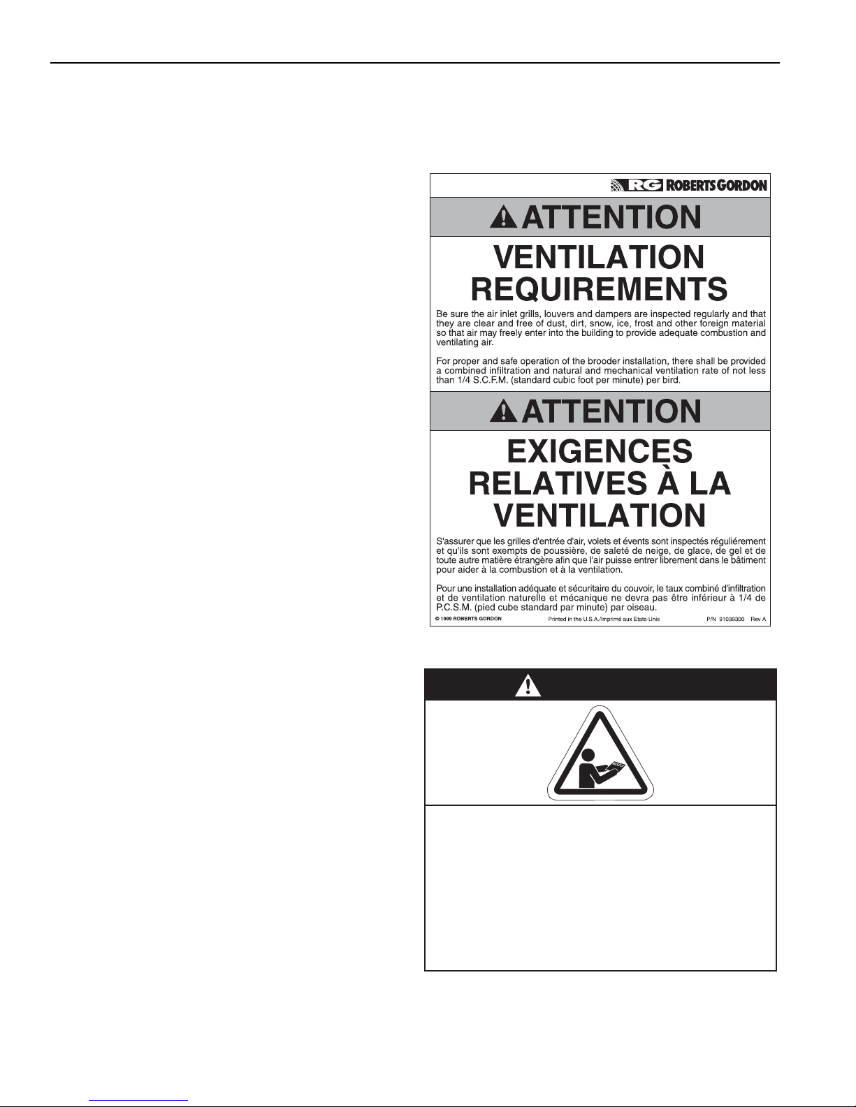
FOR YOUR SAFETY
WARNING
Installation must be done by a contractor qualified
in the installation and service of gas-fired heating
equipment or your gas supplier.
Improper installation, adjustment, alteration, service
or maintenance can result in death, injury or
property damage. Read the Installation, Operation
and Service Manual thoroughly before installing or
servicing this equipment.
If you smell gas:
1. Open windows.
2. DO NOT try to light any appliance.
3. DO NOT use electrical switches.
4. DO NOT use any telephone in
your building.
5. Extinguish any open flame.
6. Leave the building.
7. Immediately call your local gas
supplier after leaving the building.
Follow the gas supplier’s
instructions.
8. If you cannot reach your gas
supplier, call the Fire Department.
Gas-Fired, Low Intensity
Unitary Heater
Installation, Operation &
Service Manual
WARNING
Fire Hazard
Keep all flammable objects, liquids and
vapors the minimum required clearances to combustibles away from
heater.
Some objects will catch fire or explode
when placed close to heater.
Failure to follow these instructions can
result in death, injury or property
damage.
VM-80
VM-115
VM-150
VM-200
© 2012 Roberts-Gordon LLC
Installer
Please take the time to read and understand
these instructions prior to any installation.
Installer must give a copy of this manual to the owner.
Owner
Keep this manual in a safe place in order to provide
your serviceman with necessary information.
VAL-CO.
210 E. Main Street
P.O. Box 117
Coldwater, OH 45828 USA
Telephone: 800-998-2526
Fax: +1.419-678-2200
www.valcompanies.com
P/N VM34100NA Rev H 02/12
Page 2

Page 3
© 2012
Roberts-Gordon LLC
All rights reserved. No part of this work covered by the copyrights herein may be reproduced
or copied in any form or by any means - graphic, electronic, or mechanical, including
photocopying, recording, taping or information storage and retrieval systems - without the
written permission of Roberts-Gordon LLC.
TABLE OF CONTENTS
SECTION 1: Heater Safety...................................................... 1
1.1 Manpower Requirements ............................................. 1
1.2 Safety Labels and Their Placement ............................. 1
1.3 California Proposition 65 .............................................. 1
SECTION 2: Installer Responsibility ..................................... 4
2.1 Wall Tag .......................................................................4
2.2 Brooder Wall Tag .........................................................4
2.3 Corrosive Chemicals.................................................... 4
2.4 National Standards and Applicable Codes ..................5
SECTION 3: Clearances to Combustibles............................. 6
3.1 Required Clearances to Combustibles.........................6
SECTION 4: National Standards and Applicable Codes .....9
4.1 Gas Codes................................................................... 9
4.2 Aircraft Hangars ........................................................... 9
4.3 Public Garages ............................................................9
4.4 Electrical ...................................................................... 9
4.5 Venting.........................................................................9
4.6 High Altitude ................................................................ 9
SECTION 5: Major Components .......................................... 10
5.1 Standard Parts List .................................................... 11
SECTION 6: Heater Installation............................................ 12
6.1 Burner Tube Installation ............................................ 16
6.2 Tube Clamp Package Installation..............................16
6.3 Coupling and Tube Assembly....................................17
6.4 Turbulator Installation ................................................18
6.5 Reflector Installation .................................................. 19
6.6 Burner Installation...................................................... 21
SECTION 7: Optional Heater Accessories.......................... 22
7. 1 U - Tube Configuration..................................................22
7.2 Elbow Package Configuration.....................................25
7.3 Reflector Side Extension ............................................27
7. 4 L o wer Clearance Shield Installation ...........................28
7. 5 Two-Foot Decorative Grille Installation .......................28
7.6 Protective Grille Installation ........................................30
SECTION 8: Venting.............................................................. 31
8.1 Venting.......................................................................31
8.2 Unvented Operation................................................... 31
8.3 Horizontal Venting......................................................32
8.4 Vertical Venting..........................................................32
8.5 Unvented Operation T
8.6 Length Requirements ................................................32
8.7 Horizontal Ventilation 4" (10 cm) Pipe........................32
8.8 Vertical Ventilation 4" (10 cm) Pipe ............................33
8.9 Common Side Wall Venting ....................................... 33
8.10 Common Vertical Venting ........................................34
8.11 Outside Combustion Air Supply ...............................35
ube Termination ...................... 32
SECTION 9: Gas Piping........................................................ 37
SECTION 10: Wiring.............................................................. 39
10.1 Heater Wiring for use with Brooder Contoller........... 39
10.2 Standard Heater Configuration ................................ 41
10.3 Central and Satellite Heaters (Zoning Capability).... 42
10.4 Communication Wiring within a Zone of Heaters..... 44
10.4 Communication Wiring within a Zone of Heaters
(continued) ...................................................................... 45
10.5 Heat Demand Control Wiring................................... 46
10.6 Internal Wiring.......................................................... 54
10.7 Ladder Diagram ....................................................... 55
10.8 Electrical Connection to the Burner ......................... 55
10.9 Low Voltage Control Wiring Installation.................... 56
SECTION 11: Operation and Maintenance.......................... 57
11.1 S e q uence of Operation ............................................ 57
11.2 To Shut Off Heater.................................................... 57
11.3 To Start Heater ......................................................... 57
11.4 Pre-Season Maintenance and Annual Inspection..... 57
SECTION 12: Troubleshooting............................................. 60
12.1 Control LED ............................................................. 61
12.2 General LED Codes ................................................ 61
12.3 Troubleshooting Flow Chart ..................................... 63
12.4 Manifold Gas Pressure Measurement...................... 65
12.5 Pneumatic Connections........................................... 66
SECTION 13: Replacement Parts ........................................ 67
SECTION 14: General Specifications .................................. 70
14.1 Material Specifications............................................. 70
14.2 Heater Specifications............................................... 70
14.3 Suspension Specifications....................................... 70
14.4 Controls Specifications ............................................ 70
There are references in this manual to various trademarks. All trademarks mentioned herein, whether registered or not, are the
property of their respective owners. Roberts-Gordon LLC is not sponsored by or affiliated with any of the trademark or registered trademark owners, and make no representations about them, their owners, their products or services. Roberts-Gordon
LLC is not sponsored by or affiliated with BACnet® or LonWorks®.
Prin ted in U.S.A.
Page 4

Page 5

TABLE OF FIGURES
Figure 1: Top and Bottom Panel Label Placement ....................2
Figure 2: Side and Back Panel Label Placement...................... 3
Figure 3: Standard Reflector .....................................................6
Figure 4: One Side Reflector.....................................................7
Figure 5: Two Side Reflectors ................................................... 7
Figure 6: U-Tube, Standard Reflector....................................... 7
Figure 7: 2-Foot Deco Grille and Protective Grille..................... 8
Figure 8: Lower Clearance Shield* ...........................................8
Figure 9: Venting....................................................................... 8
Figure 10: Major Component Descriptions.............................. 10
Figure 11: Critical Hanger Placement...................................... 13
Figure 12: Linear Heater Assembly Overview ........................ 14
Figure 13: Linear Heater Layout Overview.............................. 15
Figure 14: U-Tube Heater Assembly Overview ......................23
Figure 15: U-Tube Heater Layout Overview ........................... 24
Figure 16: Reflector Joint Detail ..............................................26
Figure 17: Tu
Figure 18: Gas Connection with Flexible Gas Hose ...............38
Figure 19: Line Voltage Power Wiring ..................................... 39
Figure 20: Low Voltage Brooder Control Wiring ...................... 40
Figure 21: Zone Sensor Wiring Diagram.................................41
Figure 22: Central Heater Jumper Settings.............................42
Figure 23: Satellite Heater Jumper Setting..............................43
Figure 24: Communication Wiring within a Zone of Heaters ... 44
Figure 24: Communication Wiring within a Zone of Heaters
Figure 25: Thermostat Control Wiring Diagram....................... 46
Figure 26: Analog Control Signal Wiring Diagram................... 49
Figure 27: Potentiometer Control Wiring Diagram...................50
Figure 28: Modulating Thermostat Wiring Diagram
Figure 29: Modulating Thermostat Wiring Diagram
Figure 30: Modulating Thermostat Wiring Diagram with
be Termination...................................................32
(continued)............................................................. 45
(LonWorks® [4-20 mA] optional) ...........................51
(LonWorks® [2-10Vdc with 500 Ohm resistor]
optional) ................................................................. 52
BACnet® (optional) ...............................................53
LIST OF TABLES
Table 1: Contents of Burner Carton........................................ 11
Table 2: Contents of Wide Pattern Core and Wide Pattern
Extension Packages .................................................11
Table 3: VM-Series Component Package Guide .................... 11
Table 4: Cable Requirements ................................................. 48
Page 6

Page 7

SECTION 1: HEATER S AFETY
SECTION 1: HEATER SAFETY
Yo ur Safety is Important to Us!
This symbol is used throughout
the manual to notify you of possible fire, electrical or burn hazards.
Please pay special attention when
reading and following the
warnings in these sections.
Installation, Service and Annual Inspection of heater
must be done by a contractor qualified in the
installation and service of gas-fired heating
equipment.
Read this manual carefully before installation,
operation or service of this equipment.
This heater is designed for heating nonresidential
indoor spaces. Do not install in residential spaces.
These instructions, the layout drawing, local codes
and ordinances, and applicable standards that apply
to gas piping, electrical wiring, venting, etc. must be
thoroughly understood before proceeding with the
installation.
Protective gear is to be worn during installation,
operation and service. Thin sheet metal parts,
including the aluminum reflector portion of the heater
and the various
venting components, have sharp
edges. To prevent injury, the use of work gloves is
recommended. The use of gloves will also prevent
the transfer of body oils from the hands to the surface
of the reflector.
Before installation, check that the local distribution
conditions, nature of gas and pressure, and
adjustment of the appliance are compatible.
This heater must be applied and operated under the
general concepts of reasonable use and installed
using best building practices.
This appliance is not intended for use by persons
(including children) with reduced physical, sensory or
mental capabilities, or lack of experience and
knowledge, unless they have been given supervision
or instruction concerning use of the appliance by a
person responsible for their safety. Children should
be supervised to ensure that they do no play with the
appliance.
For additional copies of the Installation, Operation
and Service Manual, please contact Val-Co.
1. 1 M an p o we r R e q
uirements
To p revent personal injury and damage to the heater,
two persons will be required for installation.
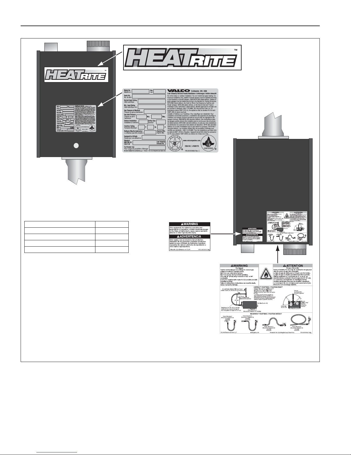
1.2 Safety Labels and Their Placement
Product safety signs or labels should be replaced by
the product user when they are no longer legible.
Please contact Val-Co or your VAL-CO independent
distributor to obtain replacement signs or labels. See
Page 2, Figure 1 through Page 3, Figure 2.
1.3 California Proposition 65
In accordance with California Proposition 65 require-
ments, a warning label must be placed in a highly
visible location on the outside of the equipment (i.e.,
near equipment’s serial plate). See label placement
drawing on Page 2, Figure 1 for label location. Avoid
placing label on areas with extreme heat, cold, corrosive chemicals or other elements. To order additional
labels, please contact Val-Co or your VAL-CO independent distributor.
1 of 71
Page 8
VM-SERIES INSTALLATION, OPERATION AND SERVICE MANUAL
Description Part Number
Logo Label 91013205
Rating Plate Label 91010405
Gas Connection Label 91018122
Proposition 65 Label 91070015
FIGURE 1: Top and Bottom Panel Label Placement
Logo Label
Bottom
Panel
Rating Plate Label
Proposition 65 Label
Top Panel
Gas Connection Label
2 of 71
Page 9
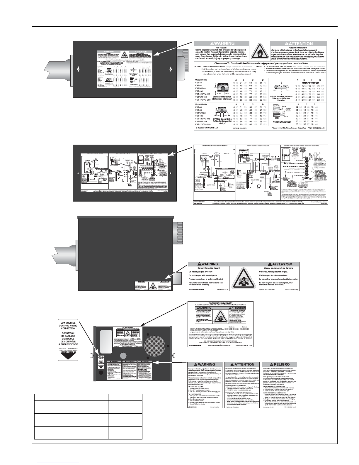
FIGURE 2: Side and Back Panel Label Placement
Lighting Instruction Plate Label
Vent Length Label
Carbon Monoxide Hazard Label
Back Panel
Inside Bottom Panel
Low Voltage
Connection
Label
COM
N.O.
Description Part Number
Clearances to Combustibles Label 91013414
Wiring Label 91013303
Carbon Monoxide Hazard Label 91039501
Low Voltage Connection Label 91039700
Vent Length Label 91039500
Lighting Instruction Plate Label 91029602
Clearances to Combustibles Label
Control Side Panel
Control Side Panel (Inside)
Wiring Label
SECTION 1: HEATER S AFETY
3 of 71
Page 10
VM-SERIES INSTALLATION, OPERATION AND SERVICE MANUAL
CAUTION
Product Damage Hazard
Do not use heater in area containing
corrosive chemicals.
Refer to appropriate Material Safety Data
Sheets (MSDS).
Failure to follow these instructions can result
in product damage.
SECTION 2: INSTALLER RESPONSIBILITY
The installer is responsible for the following:
• To install the heater, as well as the gas and
electrical supplies, in accordance with applicable
specifications and codes. Val-Co recommends
the installer contact a local Building Inspector or
Fire Marshal for guidance.
• To use the information given in a layout drawing
and in the manual together with the cited codes
and regulations to perform the installation.
• To install the heater in accordance with the
clearances to combustibles.
• To furnish all needed materials not furnished as
standard equipment.
• To plan location of supports.
• To provide access to burners for servicing on all
sides, for burner removal.
• To provide the owner with a copy of this
installation, operation and service manual.
Service Manual. See Page 6, Figure 3 through Page
8, Figure 9. Write the proper clearance dimensions in
permanent ink according to your model number and
configuration in the open spaces on the tag.
2.2 Brooder Wall Tag
• To never use heater as support for a ladder or
other access equipment and never hang or sus-
pend anything from heater.
• To ensure there is adequate air circulation arou
the heater and to supply air for combustion, venti-
lation and distribution in accordance with local
codes.
• To safely and adequately install heater using
materials with a minimal working load of 75 lbs
(33 kg).
• To ensure the heater is placed in a approved
application.
2.1 Wall Tag
A laminated wall tag is available for the heater as a
permanent reminder of the safety instructions and
the importance of the required clearances to
combustibles. Please contact Val-Co or your VAL-CO
independent distributor to obtain the wall tag. Affix
the tag by peeling off the backing of the adhesive
strips on the rear surface and position the tag on a
wall near the heater (e.g. thermostat or VAL-CO
Controller).
A copy of the wall tag (P/N 91037917) is illustrated on
the back cover. For an immediate solution, you may
affix this copy on the wall near the heater.
Know your model number and installed configuration.
Model number and installed configuration are found
on the burner and in the Installation, Operation and
nd
2.3 Corrosive Chemicals
Val-Co cannot be responsible for ensuring that all
appropriate safety measures are undertaken prior to
installation; this is entirely the responsibility of the
4 of 71
Page 11

installer. It is essential that the contractor, the sub-
contractor, or the owner identifies the presence of
combustible materials, corrosive chemicals or
halogenated hydrocarbons* anywhere in the
premises.
* Halogenated Hydrocarbons are a family of chemical
compounds characterized by the presence of halogen
elements (fluorine, chlorine, bromine, etc.). These compounds are frequently used in refrigerants, cleaning
agents, solvents, etc. If these compounds enter the air
supply of the burner, the life span of the heater components will be greatly reduced. An outside air supply must
be provided to the burners whenever the presence of
these compounds is suspected. Warranty will be invalid if
the heater is exposed to halogenated hydrocarbons.
2.4 National Standards and Applicable Codes
All appliances must be installed in accordance with
the latest revision of the applicable standards and
national codes. This refers also to the electric, gas
and venting installation. Note: Additional standards
for installations in Public Garages, Aircraft Hangars,
etc. may be applicable.
SECTION 2: INSTALLER R ESPONSIBILITY
5 of 71
Page 12
VM-SERIES INSTALLATION, OPERATION AND SERVICE MANUAL
WARNING
Fire Hazard
Keep all flammable objects, liquids and
vapors the minimum required clearances to
combustibles away from heater.
Some objects will catch fire or explode when
placed close to heater.
Failure to follow these instructions can result
in death, injury or property damage.
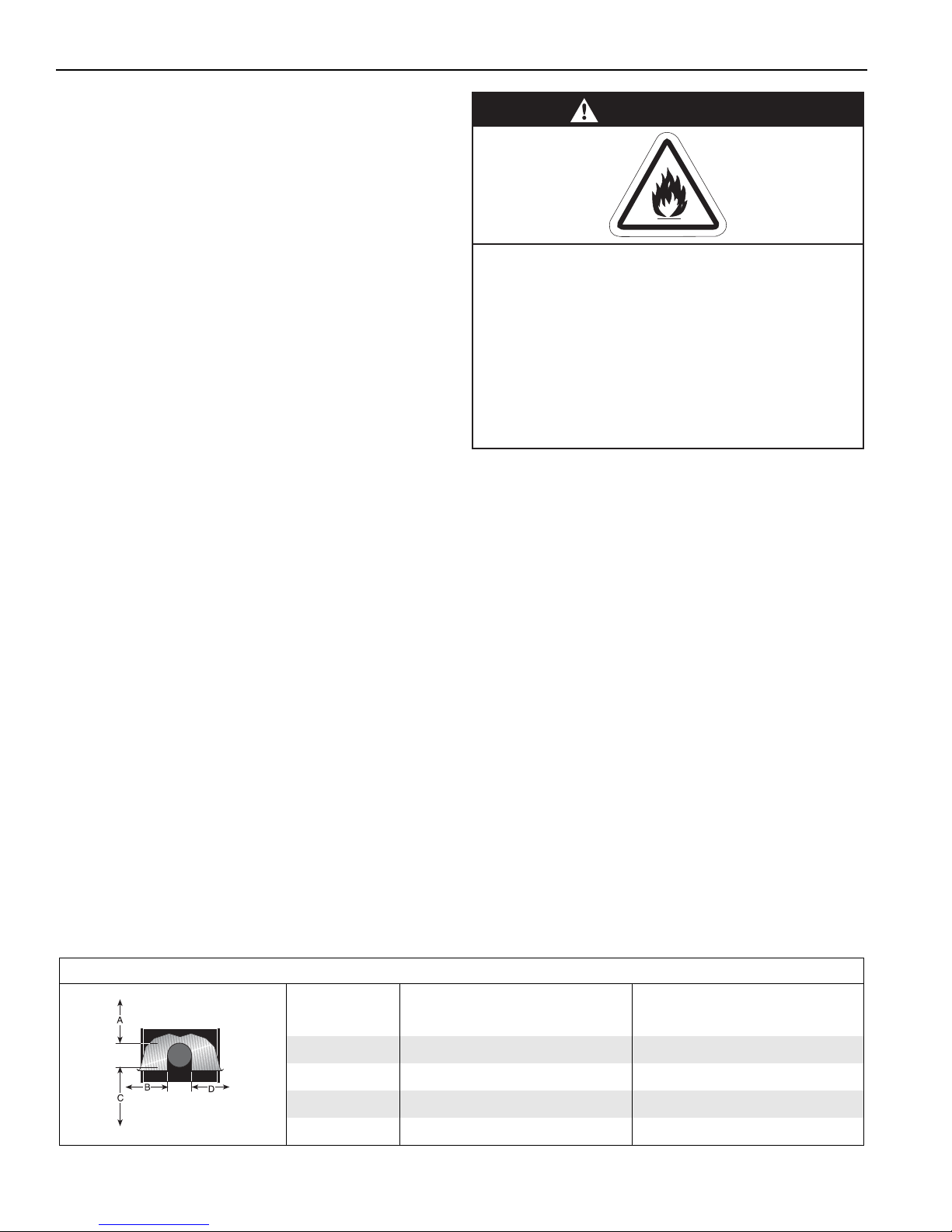
SECTION 3: CLEARANCES TO COMBUSTIBLES
3.1 Required Clearances to Combustibles
Clearances are the required distances that
combustible objects must be away from the heater to
prevent serious fire hazards. Combustibles are
materials, that may catch on fire and include common
items such as wood, paper, rubber, fabric, etc.
Maintain clearances to combustibles at all times
for safety.
Clearances for all heater models are located on the
burner of the heater and on Page 6, Figure 3 through
Page 8, Figure 9 in this manual. Check the
clearances on each burner for the model heater
being installed to make sure the product is suitable
for your application and the clearances are
maintained. Read and follow the safety guidelines
below:
• Keep gasoline or other combustible materials
including flammable objects, liquids, dust or
vapors away from this heater or any other
appliance
• The stated clearance to combustible represents a
surface temperature of 90° F (50°C) above room
temperature. Building materials with a low heat
tolerance (su
vas,triply, etc.) may be subject to degradation at
lower temperatures. It is the installer’s responsibil-
ity to assure that adjacent materials are protected
from degradation.
• Maintain clearances from heat sensitive
equipment and workstations.
• Maintain clearances from vehicles parked below
the heater.
• Maintain clearances from swinging and overhead
doors, overhead cranes, vehicle lifts, partitions,
storage racks, hoists, building construction, etc.
ch as plastics, vinyl siding, can-
• In locations used for the storage of combustible
materials, signs must be posted to specify the
maximum permissible stacking height to maintain
required clearances from the heater to the
combustibles. Signs must be posted adjacent to
the heater thermostat. In the absence of a
thermostat, signs must be posted in a
conspicuous location.
• Consult local Fire Marshal, Fire Insurance Carrier
or other authorities for approval of proposed
installation when there is a possibility of exposure
to combustible airborne materials or vapors.
• Hang heater in accordance to the minimum sus-
pension requirements
• If the radiant tubes must pass through the building
structure, be sure that adequate sleeving and fire
stop is installed to prevent scorching and/or fire
hazard.
on Page 13, Figure 11.
NOTE: 1. All dimensions are from the surfaces of all tubes, couplings and elbows.
2. Clearances B, C and D can be reduced by 50% after 25' (7.5 m) of tubing downstream
from where the burner and burner tube connect.
FIGURE 3: STANDARD REFLECTOR
Model ABCDABCD
VM-80 6 44 66 44 16 112 168 112
VM-115 6 53775316135196135
VM-150 6 58 80 58 16 146 204 146
VM-200 8 60826021153209153
6 of 71
(inches) (centimeters)
Page 13
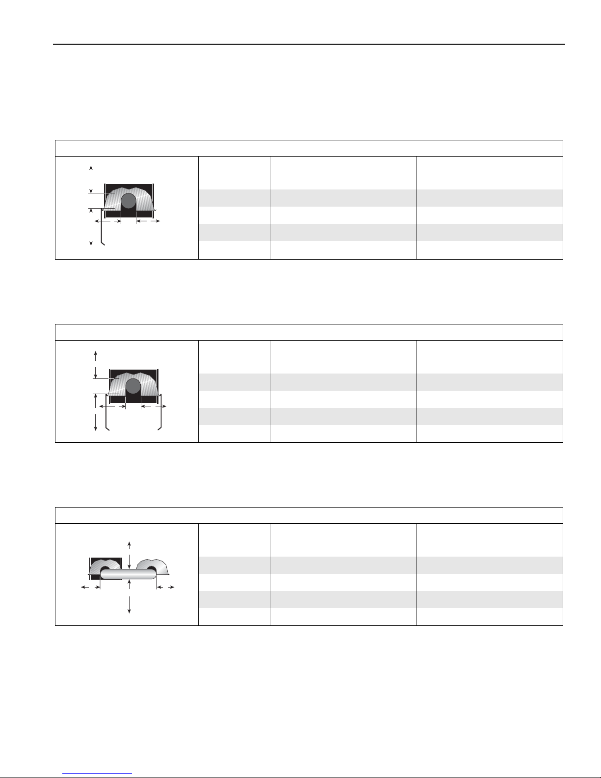
NOTE: 1. All dimensions are from the surfaces of all tubes, couplings and elbows.
A
C
D
B
A
C
D
B
A
C
D
B
2. Clearances B, C and D can be reduced by 50% after 25' (7.5 m) of tubing downstream
from where the burner and burner tube connect.
FIGURE 4: ONE SIDE REFLECTOR
Model ABCDABCD
VM-80 6 10 70 62 16 26 178 159
VM-115 6 1083751626211191
VM-150 6 10 86 79 16 26 219 202
VM-200 8 1088842126224214
SECTION 3: CLEARANCES TO COMBUSTIBLES
(inches) (centimeters)
FIGURE 5: TWO SIDE REFLECTORS
Model ABCDABCD
VM-80 6 29 72 29 16 74 183 74
VM-115 6 378437169421494
VM-150 6 40 88 40 16 102 224 102
VM-200 8 46914621117232117
FIGURE 6: U-TUBE, STANDARD REFLECTOR
Model ABCDABCD
VM-80 6 44 69 43 16 112 176 112
VM-115 6 53794916135201128
VM-150 6 58 84 54 16 146 214 138
(inches) (centimeters)
(inches) (centimeters)
VM-200 8 62875921159221150
7 of 71
Page 14
VM-SERIES INSTALLATION, OPERATION AND SERVICE MANUAL
A
C
D
B
A
C
D
B
Radiant Tubes
Vent
Pipes
Unvented
Vented
A
E
F
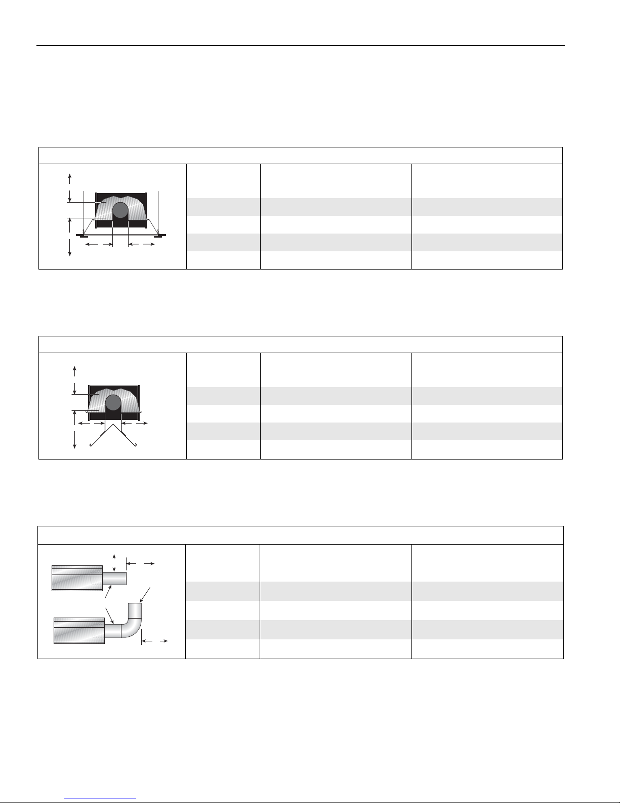
NOTE: 1. All dimensions are from the surfaces of all tubes, couplings and elbows.
2. Clearances B, C and D can be reduced by 50% after 25' (7.5 m) of tubing downstream
from where the burner and burner tube connect.
FIGURE 7: 2-FOOT DECO GRILLE AND PROTECTIVE GRILLE
(inches) (centimeters)
Model ABCDABCD
VM-80 6 44 66 44 16 112 168 112
VM-115 6 53775316135196135
VM-150 6 58 80 58 16 146 204 146
VM-200 8 60826021153209153
FIGURE 8: LOWER CLEARANCE SHIELD*
Model ABCDABCD
VM-80 6 46 38 46 16 117 97 117
VM-115 6 62486216159122159
VM-150 6 65 50 63 16 161 127 161
VM-200
*When installed in the first 10' (3 m).
FIGURE 9: VENTING
Model A E F A E F
VM-80 20 24 18 51 61 46
VM-115 20 24 18 51 61 46
VM-150 20 30 18 51 77 46
(inches) (centimeters)
- UNAPPROVED -
- UNAPPROVED -
(inches) (centimeters)
8 of 71
VM-200 20 30 18 51 77 46
Page 15
SECTION 4: NATIONAL STANDARDS AND
APPLICABLE CODES
SECTION 4: NATIONAL STANDARDS AND APPLICABLE C ODES
4.1 Gas Codes
The type of gas appearing on the nameplate
must be the type of gas used. Installation must
comply with national and local codes and
requirements of the local gas company.
United States: Refer to National Fuel Gas Code
NFPA 54/ANSI Z223.1 - latest revision.
Canada: Refer to Natural Gas and Propane
Installation Code CSA B149.1 - latest revision.
4.2 Aircraft Hangars
Installation in aircraft hangars must be in
accordance with the following codes:
United States: Refer to Standard for Aircraft
Hangars, NFPA 409 - latest revision.
Canada: Refer to Natural Gas and Propane
Installation Code CSA B149.1 - latest revision.
In aircraft storage and servicing areas, heaters
shall be installed at least 10' (3 m) above the
upper surface of wings or of engine enclosures
of the highest aircraft which may be housed in
the hangar. The measurement shall be made
from the wing or engine enclosure (whichever is
higher from the floor) to the bottom of the heater.
• In shops, offices and other sections of aircraft
hangars communicating with aircraft storage or
servicing areas, heaters shall be installed not
less than 8' (2.4 m) above the floor.
• Suspended or elevated heaters shall be so
located in all spaces of aircraft hangars that they
shall not be subject to injury by aircraft, cranes,
movable scaffolding or other objects. Provisions
shall be made to assure accessibility to
suspended heaters for recurrent maintenance
purposes.
4.3 Public Garages
Installation in garages must be in accordance
with the following codes:
United States: Refer to Standard for Parking
Structures NFPA 88A - latest revision or the
Code for Motor Fuel Dispensing Facilities and
Repair Garages, NFPA 30A - latest revision.
Canada: Refer to Natural Gas and Propane
Installation Code CSA B149.1 - latest revision.
• Heaters must not be installed less than 8'
(2.4 m) above the floor. Minimum clearances to
combustibles must be maintained from vehicles
parked below the heater.
• When installed over hoists, minimum
clearances to combustibles must be maintained
from the upper most point of objects on the hoist.
4.4 Electrical
The heater must be electrically grounded in
accordance with the following codes:
United States: Refer to National Electrical Code
NFPA 70 - latest revision. Wiring must conform to
the most current National Electrical Code
®
, local
ordinances and any special diagrams furnished.
Canada: Refer to Canadian Electrical Code,
CSA C22.1 Part 1 - latest revision.
4.5 Venting
The venting must be installed in accordance with
the requirements within this manual and the
following codes:
United States: Refer to National Fuel Gas Code
NFPA 54/ANSI Z223.1 - latest revision.
Canada: Refer to Natural Gas and Propane
Installation Code CSA B149.1 - latest revision.
®
,
4.6 High Altitude
These heaters are approved for installations up
to 2000' (610 m)(US), 4500' (1370 m)(Canada)
without modification. Consult factory if US
installation is above 2000' (610 m) or Canadian
installation is above 4500' (1370 m).
9 of 71
Page 16
VM-SERIES INSTALLATION, OPERATION AND SERVICE MANUAL
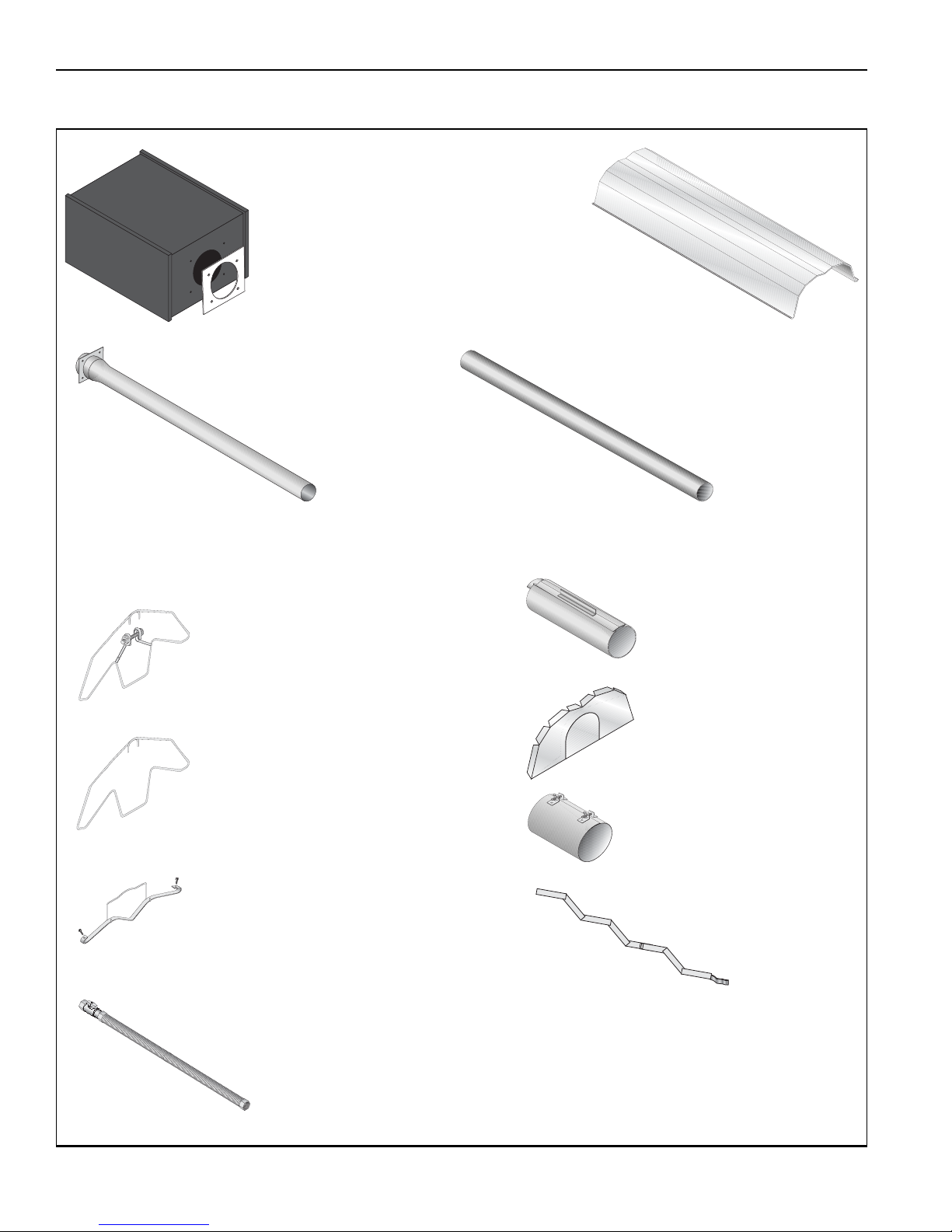
Burner with Tube Gasket
Must be installed with the
flame observation
window facing down.
Reflector
(Aluminum or
Stainless
Steel)
Alternate overlap as
shown on overview and
on Page 15, Figure 13.
Minimum overlap is 6" (16 cm).
Tube and Reflector Hanger,
Wide Pattern with Clamp
Package
Position this hanger no more
than 4" (10 cm) away from the
burner.
Coupling Assembly
with Lock
Reflector End Cap
Punch out center
section to
accommodate tube.
Tube and Reflector Hanger,
Wide Pattern
Suspend system from these
hangers.
Flex Gas Line with
Shut Off Cock
Tube
Heat treated
aluminized tube supplied
in 10' (3 m) lengths.
Burner Tube
Supplied in 10
'
(3 m) lengths. Burner
tube is always the first tube
after the burner.
Reflector Support Strap,
Wide Pattern & Wire Form
Turbulator
Turbulator must
be installed in the last
standard section of tube.
Turbulator is not required on the
VM-200. For installation see
Page 18, Section 6.4.
Vent Adapter
SECTION 5: MAJOR COMPONENTS
FIGURE 10: Major Component Descriptions
10 of 71
Page 17
SECTION 5: MAJOR COMPONENTS
5.1 Standard Parts List
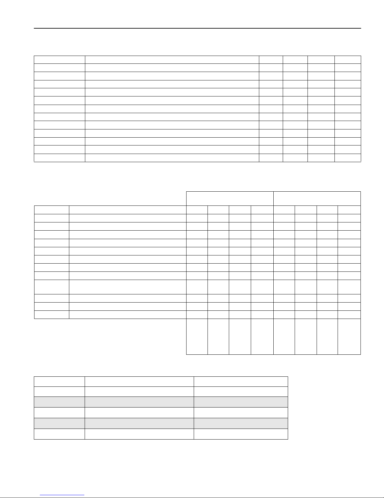
Table 1:
*Canadian Models: Rubber (Type 1) Gas Hoses available as an accessory.
Contents of Burner Carton
Part No. Description VM-80 VM-115 VM-150 VM-200
VM34XXXXX Burner Assembly (Rate and Fuel Varies) 1 1 1 1
02568200 Gasket (Burner to Burner Tube) 1 1 1 1
VM34100NA Installation, Operation and Service Manual 1 1 1 1
94273914 Hex Head Bolts 5/16-18 Rolok 4 4 4 4
96411600 Split Lock Washer 4 4 4 4
91201708 Pipe Nipple (Black) 1/2" NPT x 4" 1 1 1 1
*91412200 Flexible Stainless Steel Gas Hose - 1/2" NPT (US Models Only) 1 1 - -
*91412204 Flexible Stainless Steel Gas Hose - 3/4" NPT (US Models Only) - - 1 1
03051503 Turbulator Adapter 1 1 1 -
03051504 Turbulator, Aluminized Steel 3 3 1 -
91317310 Wire Terminal Receptacle.187 x.032 8 8 8 8
91309605 Cable Grommet with Tie 1 1 1 1
See Page 37, Section 9
.
Table 2: Contents of Wide Pattern Core and Wide Pattern Extension Packages
Wide Pattern
Core Packages (Aluminized)
Part No. Description 10
91409408 Tube, HT Aluminized, 10' (3m) - 1 2 3 1 2 3 4
03051101
03051601
01312700 Coupling Assembly - 1 2 3 1 2 3 4
02750303 Standard Reflector, 8
02750800 End Cap 2 2 2 2 - - - -
03090101 Tube and Reflector Hanger, Wide Pattern 2 3 4 5 1 2 3 4
91907302 S-Hook 2 3 4 5 1 2 3 4
03050011 Reflector Support Package, Wide Pattern
91107720 U-Clip Package 1 1 1 1 1 1 1 1
90502700 Vent Adapter 1 1 1 1 - - - -
01318901 Tube Clamp Package 1 1 1 1 - - - -
Burner Tube, ALUMI-THERM
Burner Tube, HT ALUMI-THERM
(Strap, Wire Form, Screws)
®
Steel, 10' (3m)
®
Steel, 10' (3m)
'
(3.5m) 2 3 4 6 2 3 4 6
Part Number
' (3m)20' (6m)30' (9m)40' (12m)10' (3m)20' (6m)30' (9m)40' (12m)
--11--- -
11 - - - - - -
123 5 234 6
CPW10ALUM
CPW20ALUM
CPW30ALUM
Extension Packages (Aluminized)
CPW40ALUM
EXPW10ALUM
Wide Pattern
EXPW20ALUM
EXPW30ALUM
Table 3: VM-Series Component Package Guide
EXPW40ALUM
Model Tubing Length Wide Pattern Core Packages
Minimum Aluminized
VM-80 20' (6m) CPW20ALUM
VM-115 30' (9m) CPW30ALUM
VM-150 40' (12m) CPW40ALUM
VM-200 50' (15m) CPW30ALUM + EXPW20ALUM
Additional tubing length may be added to heater. Tubing must be heat-treated, aluminized or porcelain
coated. Any additional tubing lengths are considered as vent length for length determination. Maximum
venting length for minimum heater length is 45' (13.7 m) total.
11 o f 7 1
Page 18
VM-SERIES INSTALLATION, OPERATION AND SERVICE MANUAL
WARNING
Cut/Pinch Hazard
Wear protective gear during installation,
operation and service.
Edges are sharp.
Failure to follow these instructions can result
in injury.
SECTION 6: HEATER INSTALLATION
WARNING
Severe Injury Hazard
Secure burner to burner tube with bolts and
lockwashers.
Hang heater with materials with a minimum
working load of 75 lbs (33 kg).
Failure to follow these instructions can result
in death, injury or property damage.
Expansion and contraction of the tube dictates that
the minimum suspension lengths in the table on
Page 13, Figure 11 be maintained.
To ensure your safety, and comply with the terms of
the warranty, all units must be installed in
accordance with these instructions.
The gas or the electrical supply lines must not be
used to support the heater.
Do not locate the gas or electric supply lines directly
over the path of the flue products from the heater.
The heater must be installed in a location that it is
readily accessible for servicing.
The heater must be installed in accordance with
clearances to combustibles as indicated on the
heater and in this instruction manual.
The gas inlet pressure must be maintained as
indicated on the rating plate.
Typical installation configurations are shown on Page
13, Figure 11.
12 of 71
Page 19
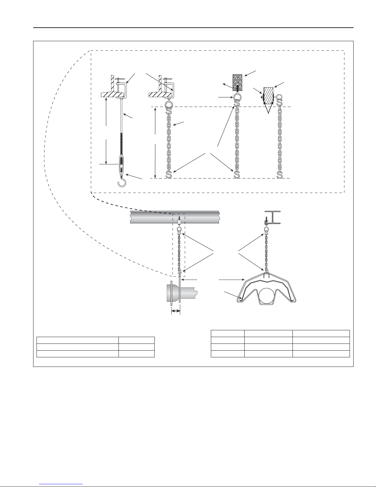
FIGURE 11: Critical Hanger Placement
Hanger
Side View
Must Be Within 4" (10 cm) Front View
S-hooks
Reflector
* Allows for thermal expansion of system
Typical Suspension Details
Rod 3/8"
Beam Clamp
Concrete Beam
Wood Beam
Washers
Locknut
Screw Hook
3/8"
24" min.*
(61 cm)
"X"*
Anchor
S-hooks
Chain Size
3/16"
Minimum
Turnbuckle
Not Included
Description Part Number
S-Hook 91907302
Tube/Reflector Hanger, Wide Pattern 03090101
Run Length Typical Expansion Minimum "X" Length
10' - 50' ±1" (3 cm) 12"
51' - 60' ±2" (5 cm) 18"
61' - 70' ±3" (8 cm) 24"
SECTION 6: HEATER I NSTALLATION
13 of 71
Page 20
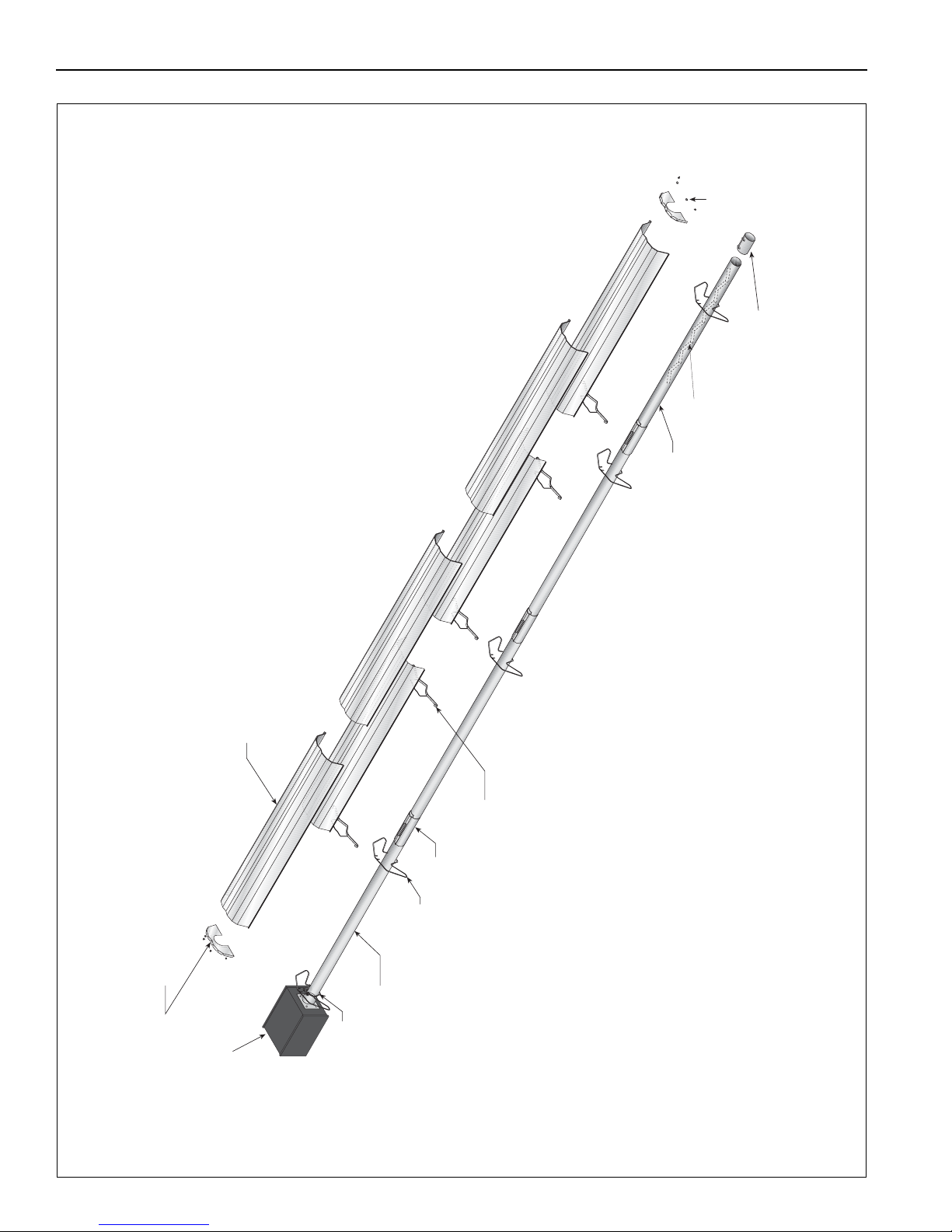
VM-SERIES INSTALLATION, OPERATION AND SERVICE MANUAL
Tube
Reflector
Reflector End Cap
Reflector Support,
Wide Pattern
Burner
Coupling
U-Clips
Burner Tube
Tube and Reflector Hanger,
Wide Pattern
Tube Clamp
Package
Vent Adapter
Turbulator
(With Select Models)
FIGURE 12: Linear Heater Assembly Overview
14 of 71
Page 21
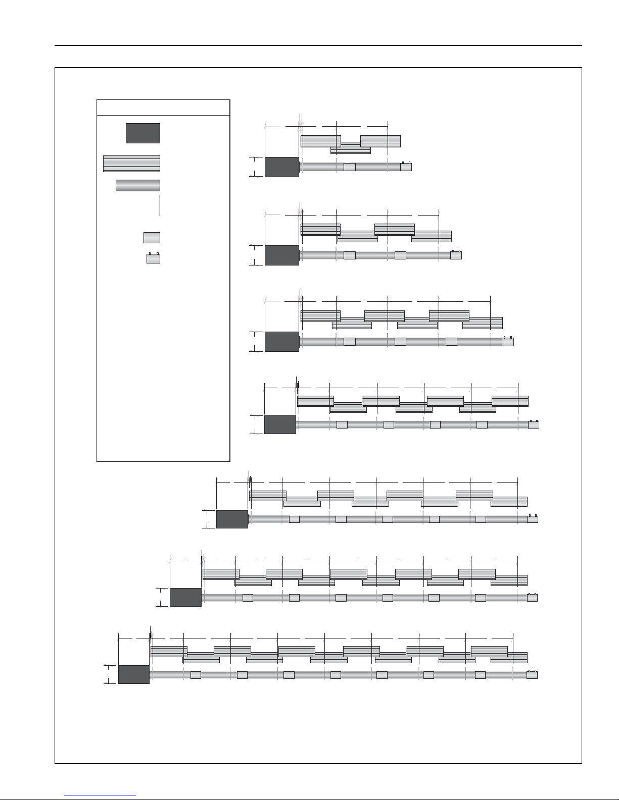
FIGURE 13: Linear Heater Layout Overview
Burner
Reflector
Tube
Tube/Reflector
Hanger,
Wide Pattern
Coupling
Assembly
Vent Adapter
LEGEND
a = 14" (36 cm)
reflector width (not shown)
b = 2" (5 cm)
end cap to burner
c = 2" (5 cm)
end cap to hanger
d = 7'6" (229 cm)
distance first hanger
e = 10' (305 cm)
distance between hangers
f = 9.5" (24 cm)
burner height
g = 17.5" (44 cm)
burner length
g
c
b
de
e e e e
f
g
c
b
de
e e e
f
g
c
b
de
e e
f
g
c
b
de
f
20' (6 m) Tube Length
g
c
b
de
e
f
30' (9 m) Tube Length
40' (12 m) Tube Length
50' (15 m) Tube Length
60' (18 m) Tube Length
b
f
g
c
de
e e e e e
70' (21 m) Tube Length
b
b
f
g
c
de
e e e e e
80' (24 m) Tube Length
b
e
SECTION 6: HEATER I NSTALLATION
15 of 71
Page 22
VM-SERIES INSTALLATION, OPERATION AND SERVICE MANUAL
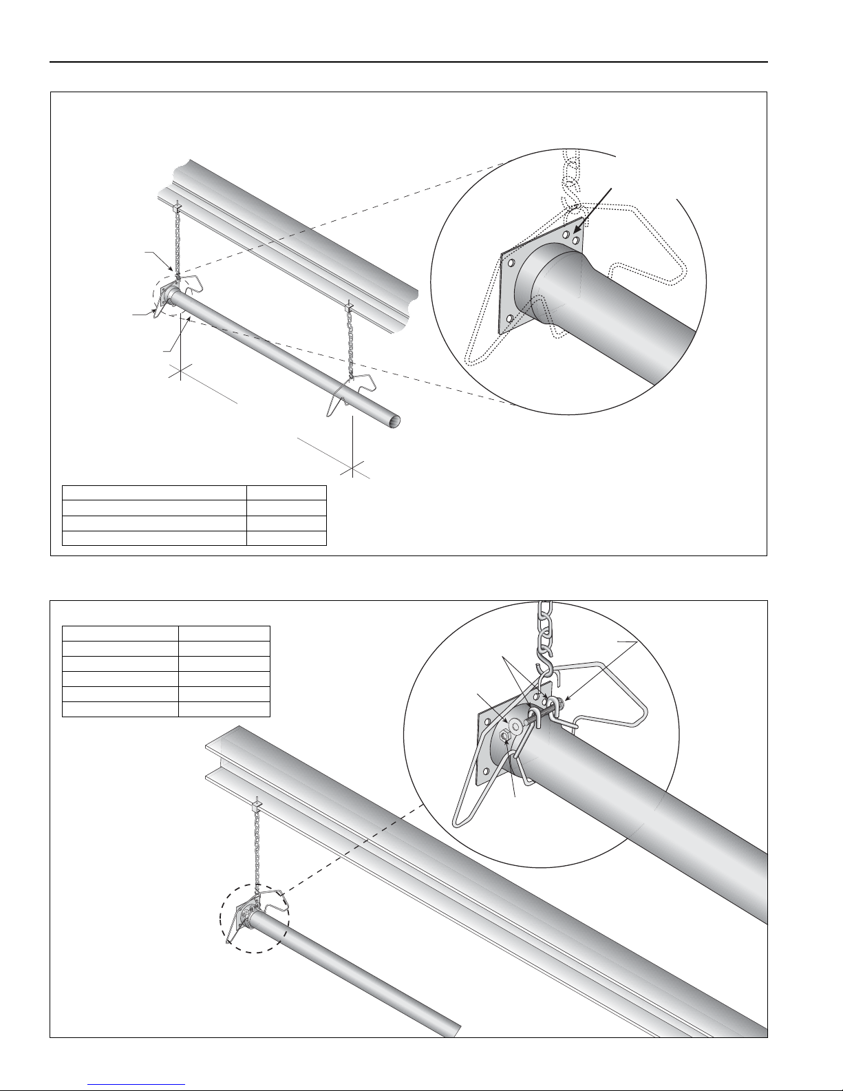
7' 6" ± 1'
(229 cm ± 25 cm)
NOTE:
Tubing requires a downward
slope of 1/2" (13 mm)
per 20
' (6 m) away
from burner.
S-Hook
Burner Tube
Hanger,
Wide Pattern
Offset mounting
hole must be
to the top.
Weld seam
must be to the
bottom of the tube.
Description Part Number
Burner Tube 03051XXX
S-Hook 91907302
Tube/Reflector Hanger, Wide Pattern 03090101
Bolt
Tube Clamp
Flat
Washer
Nut
(Torque 120 in/lb
13.56 Nm)
Description Part Number
Tub e C lamp Pack age01318901
Tube Clamp 01396801
Bolt 97113940
Flat Washer 95211600
Nut 92113900
Step 6.1 Burner Tube Installation
Step 6.2 Tube Clamp Package Installation
16 of 71
Page 23
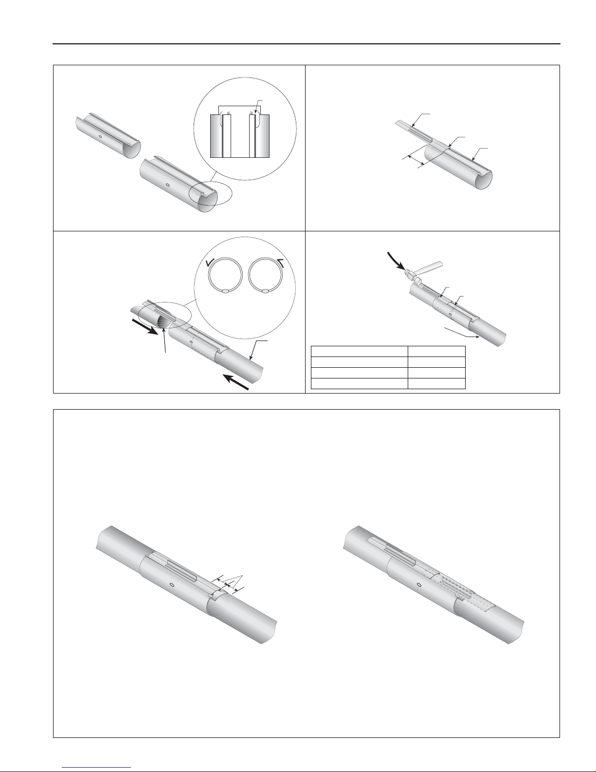
Step 6.3 Coupling and Tube Assembly
Tube
Tube
Orient coupling so that
the impact block is in the
2:00 or 10:00 oclock
positions.
Closed
Open
Tab
3" (8 cm) to
4" (10 cm)
Slide Bar/Coupling Lock
Coupling
Wide End
Coupling
Tube
Slide Bar/Coupling Lock
A
Close coupling
with tab.
B
Start Slide bar/Coupling
Lock.
C
Insert tubes into coupling.
D
Tighten coupling to join tubes.
Description Part Number
Coupling 01329600
Slide bar/Coupling Lock 01329700
Tube 91409XXX
Incorrect slide bar
position
Correct slide bar
dimensions
± 2" (5 cm)
Drive slide bar until tight.
End of slide bar should be
within tolerance listed below.
• Repeat Step 6.3 A - D until all tubes are assembled. See Page 18, Section 6.3.2.
Tighten slide bar as shown below.
SECTION 6: HEATER I NSTALLATION
Step 6.3.1 Coupling and Tube Assembly (Continued)
17 of 71
Page 24
VM-SERIES INSTALLATION, OPERATION AND SERVICE MANUAL
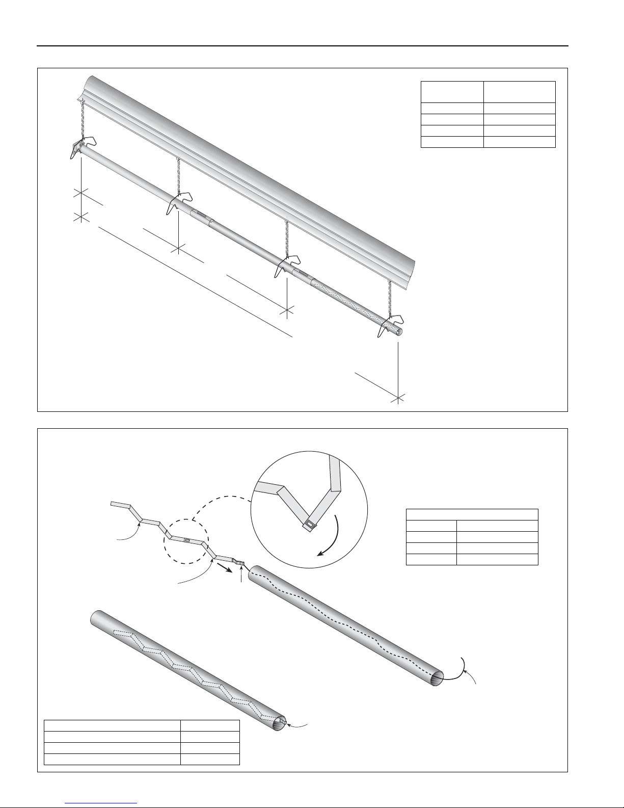
10' ± 1'
(305 cm ± 25 cm)
Total Overall
Tube Length
7' 6" ± 1'
(229 cm ± 25 cm)
Model
Tube L e n gth
Minimum
VM-80 20’ (6 m)
VM-115 30’ (9 m)
VM-150 40’ (12 m)
VM-200 50’ (15 m)
T
w
i
s
t
Pull String
Tab
Fold tab around outside
of tube nearest to the vent to
hold turbulator in place.
Turbulator
Section
Turbulator
Adapter
Description Part Number
Turbulator Adapter 03051503
Turbulator Section 03051504
Tube 91409XXX
Turbulator Installation
VM-80 2nd 10' Section
VM-115 3rd 10' Section
VM-150 4th 10' Section
VM-200 N/A
Turbulator must be installed in
the last standard section of
tube. Turbulator is not required
on the VM-200.
Step 6.3.2 Coupling and Tube Assembly (Continued)
Step 6.4 Turbulator Installation
18 of 71
Page 25
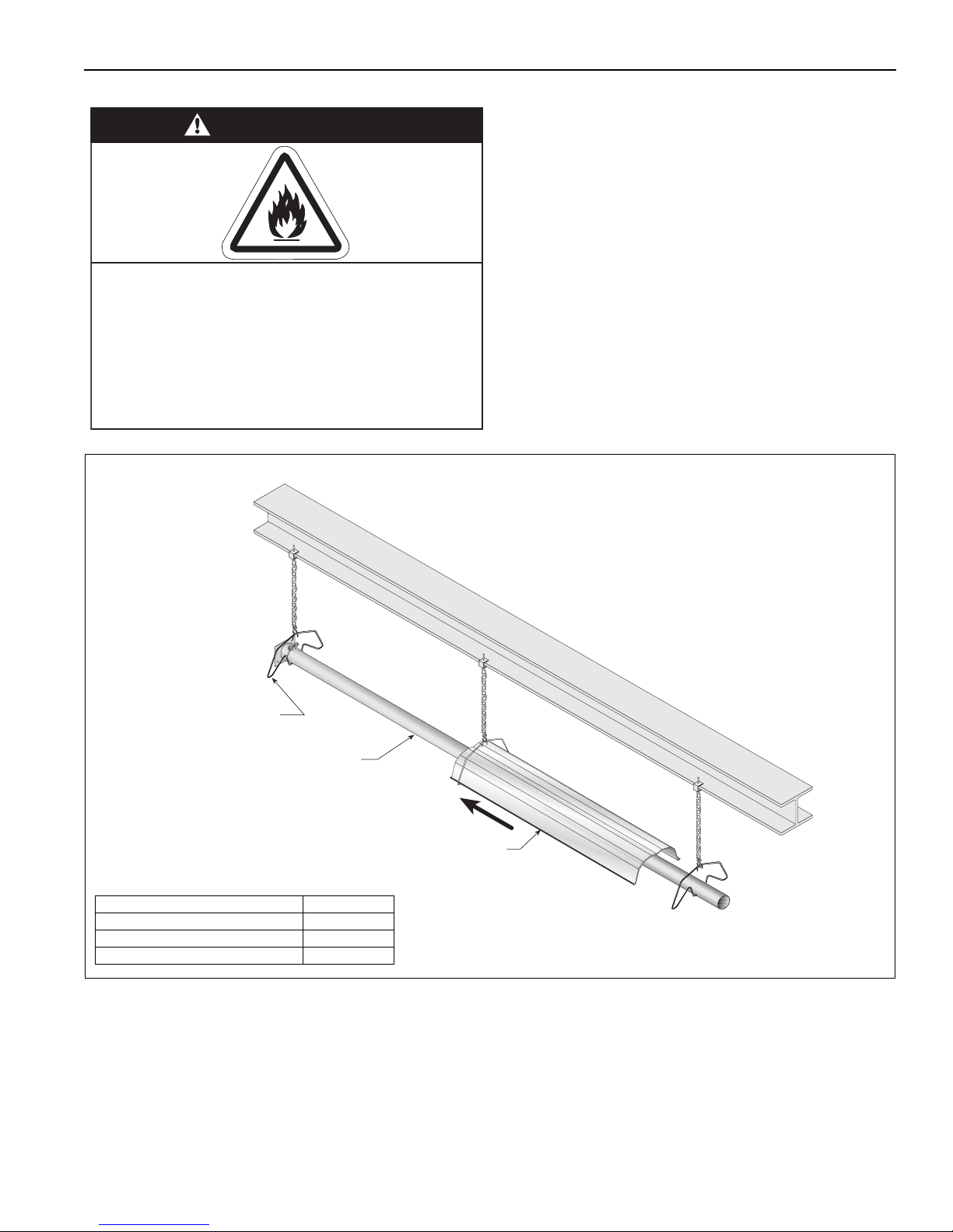
6.5 Reflector Installation
WARNING
Fire Hazard
Support reflector with reflector hanger
and support strap.
Reflector must not touch tube.
Failure to follow these instructions can result
in death, injury or property damage.
Hanger,
Wide Pattern
Burner Tube
Reflector
Description Part Number
Tube/Reflector Hanger, Wide Pattern 03090101
Burner Tube 03051XXX
Reflector 02750303
NOTE: All tube surfaces must be covered
by a reflector, except for a U-Tube.
SECTION 6: HEATER I NSTALLATION
19 of 71
Page 26
VM-SERIES INSTALLATION, OPERATION AND SERVICE MANUAL
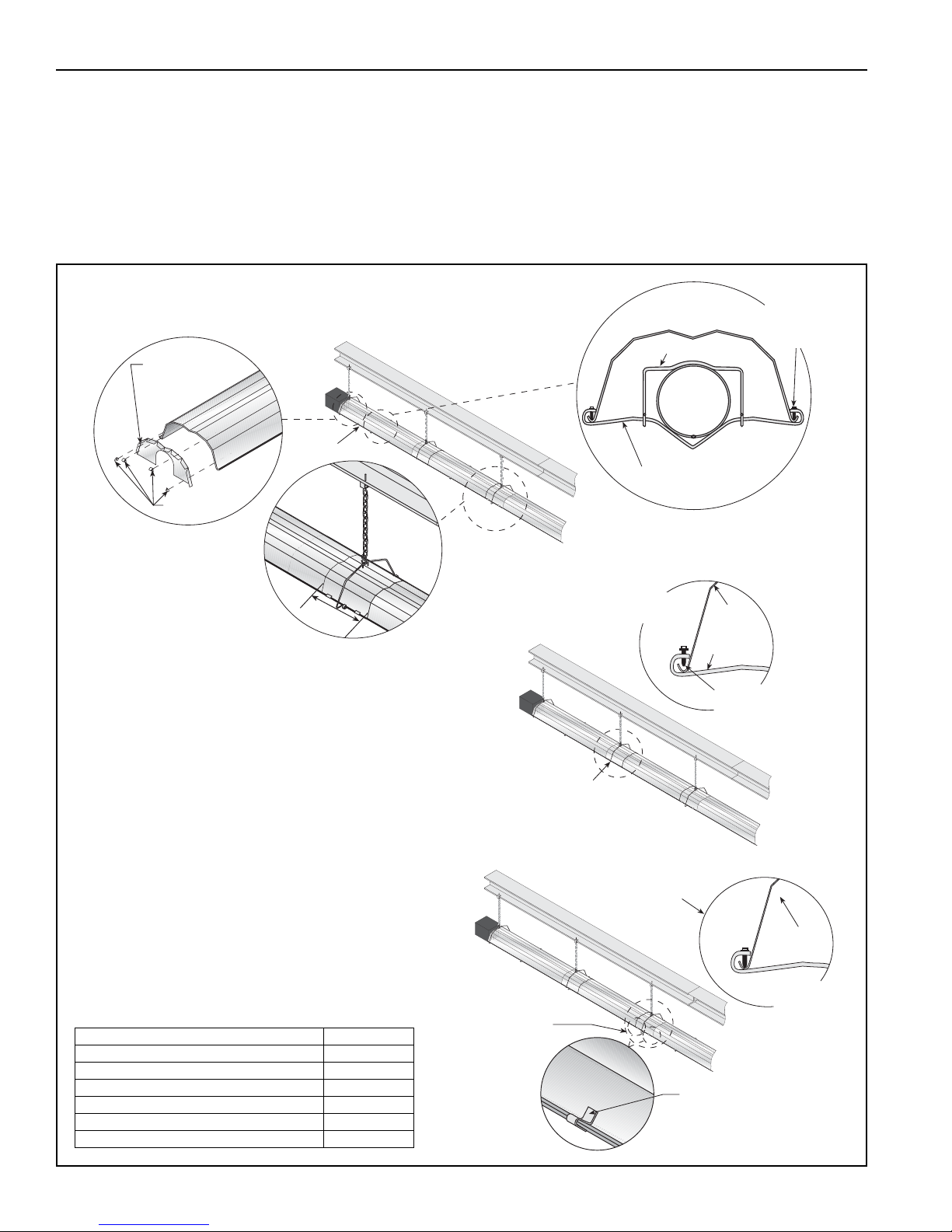
2. The overlap at the first and second reflector is a slip overlap.
Thereafter, every third reflector joint is a slip overlap. A slip
overlap is achieved by either:
a.) both reflectors lay inside a hanger.
(No reflector support needed.)
b.) using a reflector support with
loose screws at the reflector
overlap.
3. The remaining reflector overlaps require a non-slip
overlap connection. To affix the reflectors together in
a non-slip overlap either:
a.) use reflector support and tight screws.
b.) if both reflectors lay inside a hanger, u-clips or
sheet metal screws may be used.
This section of three reflectors joined together must
be affixed to the tube with at least one reflector support
with tight screws.
Reflector
End Cap
U-clips
1. The first reflector after the burner must be affixed in
the middle of the reflector with a reflector support and
tight screws.
First Reflector
6"
(16 cm)
Overlap must be a
minimum of
6
" (16 cm).
Loose screws
loosened 1/16"
(.16 cm) to allow
slippage.
2 A
Slip Overlap
Reflector
Support
2 B
Slip Overlap
Reflector
Tight
Screws
3 B
Non-Slip Overlap
U-clip
(2 Clips per
Non-slip Overlap
Inside a Hanger)
Reflector
3 A
Non-Slip Overlap
Wire Form
Reflector Support
Strap
Tight
Sheet Metal
Screw
Description Part Number
Reflector Support Package, Wide Pattern 03050 011
Wire Form 91908004
Reflector Support Strap, Wide Pattern 03050001
Screw #8 x 3/4" 94320812
U-Clip Package 91107720
Reflector End Cap 027508XX
Step 6.5.1 Reflector, U-Clip and Reflector Support Installation
The pictorial drawings of the heater construction in
Section 6 are schematic only and provide a general
guideline of where hangers, reflector supports and
U-clips are to be installed.
To ensure proper expansion and contraction
movement of the reflectors, a combination of U-clips
and reflector supports are used. The positioning of
reflector supports and U-clips depends on the
individual installation. Use either pop rivets or sheet
metal screws instead of u-clips when installing end
caps and joint pieces in areas where impact and high
wind may be a factor. The following rules must be
observed.
20 of 71
Page 27
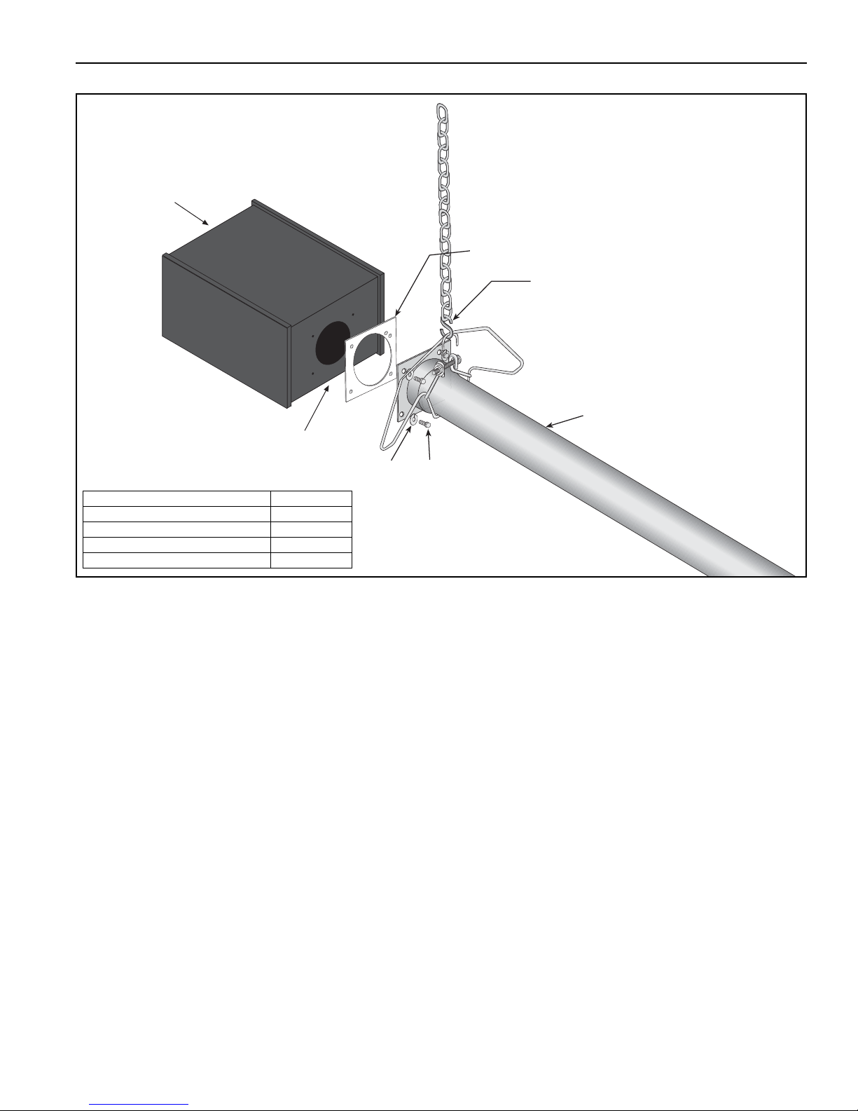
Step 6.6 Burner Installation
Lock
Washer
Gasket
Burner
Bolt
(Torque 120 in/lb
13.56 Nm)
S-hook
Burner Tube
Burner must be installed
with the flame observation
window facing down.
Description Part Number
Bolt 94273914
Burner VM34XXXXX
Lock Washer 96411600
Gasket 02568200
SECTION 6: HEATER I NSTALLATION
21 of 71
Page 28
VM-SERIES INSTALLATION, OPERATION AND SERVICE MANUAL
WARNING
Cut/Pinch Hazard
Wear protective gear during installation,
operation and service.
Edges are sharp.
Failure to follow these instructions can result
in injury.
SECTION 7: OPTIONAL HEATER ACCESSORIES
7.1 U-Tube Configuration
Heaters are approved for optional U-Tu be
configurations.
The U-Tube may be installed in a standard horizontal
position. When using a U-Tube configuration, the
following additional rules must be adhered to:
• A minimum of 10' (3 m) on VM-80 and a minimum
of 15' (4.5 m) on VM-115/150/200 is required
between the burner and the U-Tube.
• The correct turbulator (See Page 18, Figure 6.4)
must be installed in the last standard section of
tube.
• The burner must never be operated in a tilted
position.
• The heater must be properly supported at all locations. See Page 24, Figure 15.
22 of 71
Page 29
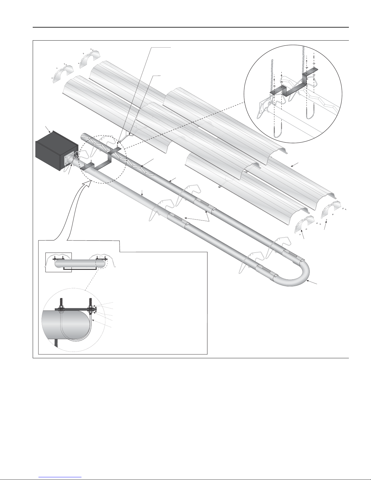
FIGURE 14: U-Tube Heater Assembly Overview
U-Tube
18" (457 mm)
Center to Center
U-Clips
Reflector
End Caps
12
1
2
Burner
Reflector
(Turbulator
With Select
Models)
Tube Clamp
Package
Burner
Tube
Tube
U-Tube
Support Bracket
Reflector
Support,
Wide Pattern
Couplings
U-Tube, Stand ard
Lock Washer
Lock Washer
Nut
Nut
U-Bolt
Tight U-Bolt
4" (10 cm) U-Bolt,
secured to Burner Tube
with 1/4" (6 mm)
Lockwashers and
1/4-20 Hex Nuts
Loose U-Bolt
4" (10 cm) U-Bolt,
secured to Bracket with
1/4" (6 mm) Lockwashers
and 1/4-20 Hex Nuts on
top and bottom to
allow for tube expansion
and contraction
SECTION 7: OPTIONAL H EATER ACCES SORIES
23 of 71
Page 30
VM-SERIES INSTALLATION, OPERATION AND SERVICE MANUAL
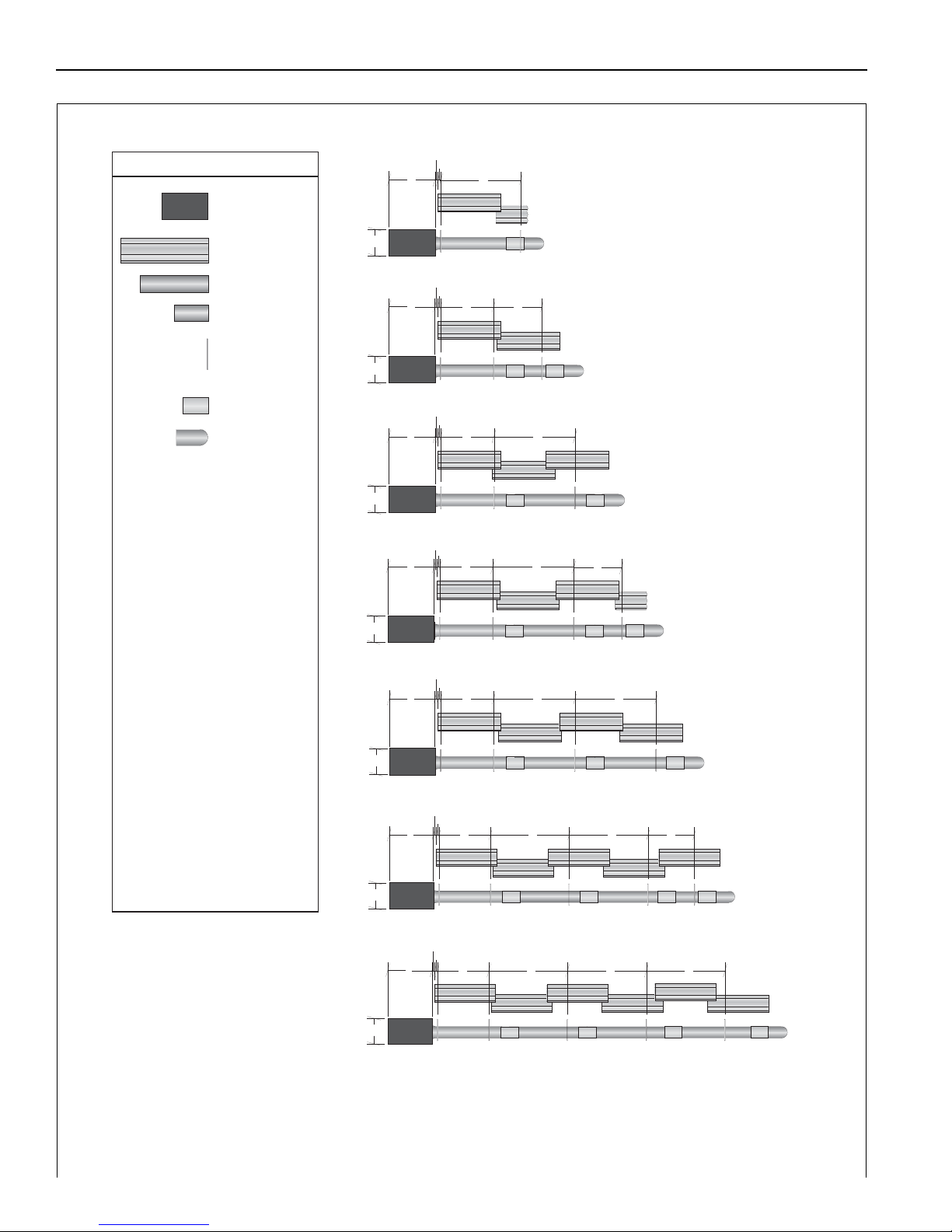
LEGEND
a = 14" (36 cm)
reflector width (not shown)
b = 2" (5 cm)
end cap to burner
c = 2" (5 cm)
end cap to hanger
d = 7'6" (229 cm)
distance first hanger
e = 10' (305 cm)
distance between hangers
f = 5' (153 cm)
distance between last full tube
hanger and half tube hanger
g = 17.5" (44 cm)
burner length
h = 9.5" (24 cm)
burner height
*Requires the last reflector
before the u-tube to be cut
in half for use on both sides.
**Requires the last tube before
the u-tube to be cut in half for
use on both sides.
U-tube
Burner
Reflector
Tube 10' (3 m)
Tube/Reflector
Hanger,
Wide Pattern
Coupling
Assembly
c
b
de
e
g
60' (18 m) Tube Length
c
b
de
g
h
40' (12 m) Tube Length
c
b
de
f
g
h
50' (15 m) Tube Length* **
g
c
b
20' (6 m) Tube Length*
h
e
Tube 5' (1.5 m)**
c
b
d
f
g
h
30' (9 m) Tube Length**
c
b
de
e
f
g
h
70' (21 m) Tube Length**
c
b
de
e
g
h
80' (24 m) Tube Length
e
h
FIGURE 15: U-Tube Heater Layout Overview
24 of 71
Page 31
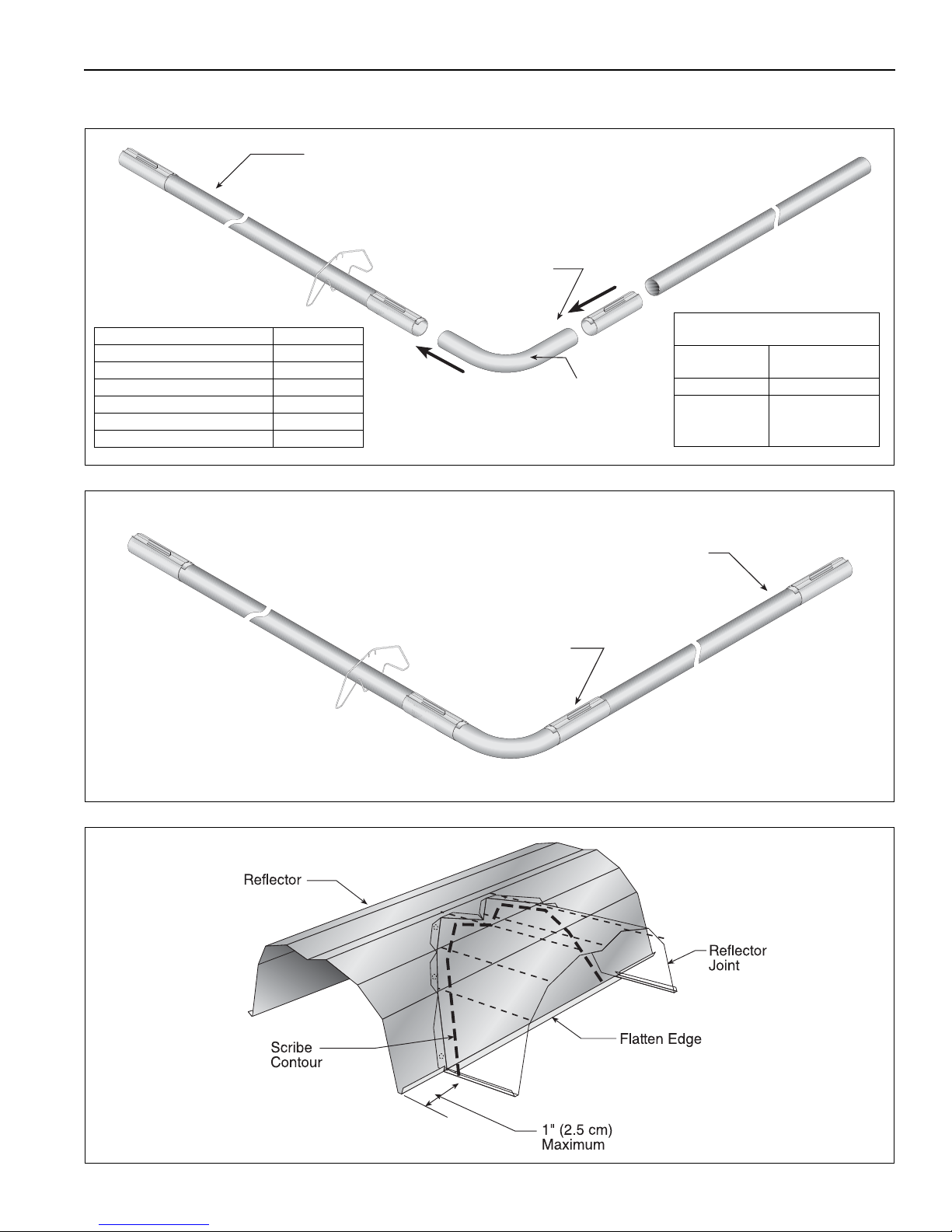
7. 2 E l b ow P a c k a ge Configuration
Tube
90° Elbow
Coupling
Description Part Number
Elbow Package 02718702
90° Elbow 01335801
Coupling 01312700
Reflector End Cap 02750800
Reflector Joint Piece 02750900
U-clip Package 91107720
Minimum Distance Required
Between Burner and Elbow
Model
Minimum
Distance
VM-80 10' (3m)
VM-115
VM-150 15' (4.5m)
VM-200
Tube
Coupling
Step 7.2.1 Elbow Installation
Step 7.2.2 Elbow Installation
SECTION 7: OPTIONAL H EATER ACCES SORIES
Step 7.2.3 Reflector Joint Installation
25 of 71
Page 32
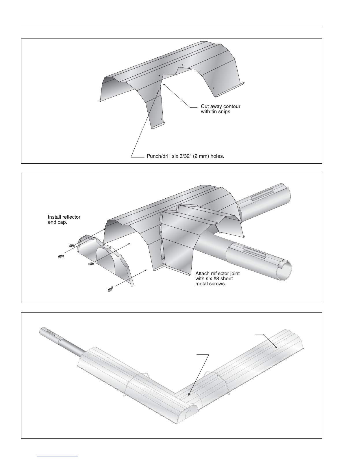
VM-SERIES INSTALLATION, OPERATION AND SERVICE MANUAL
Reflector
Reflector
Joint
Step 7.2.4 Reflector Joint Installation
Step 7.2.5 Reflector Joint Detail
FIGURE 16: Reflector Joint Detail
26 of 71
Page 33
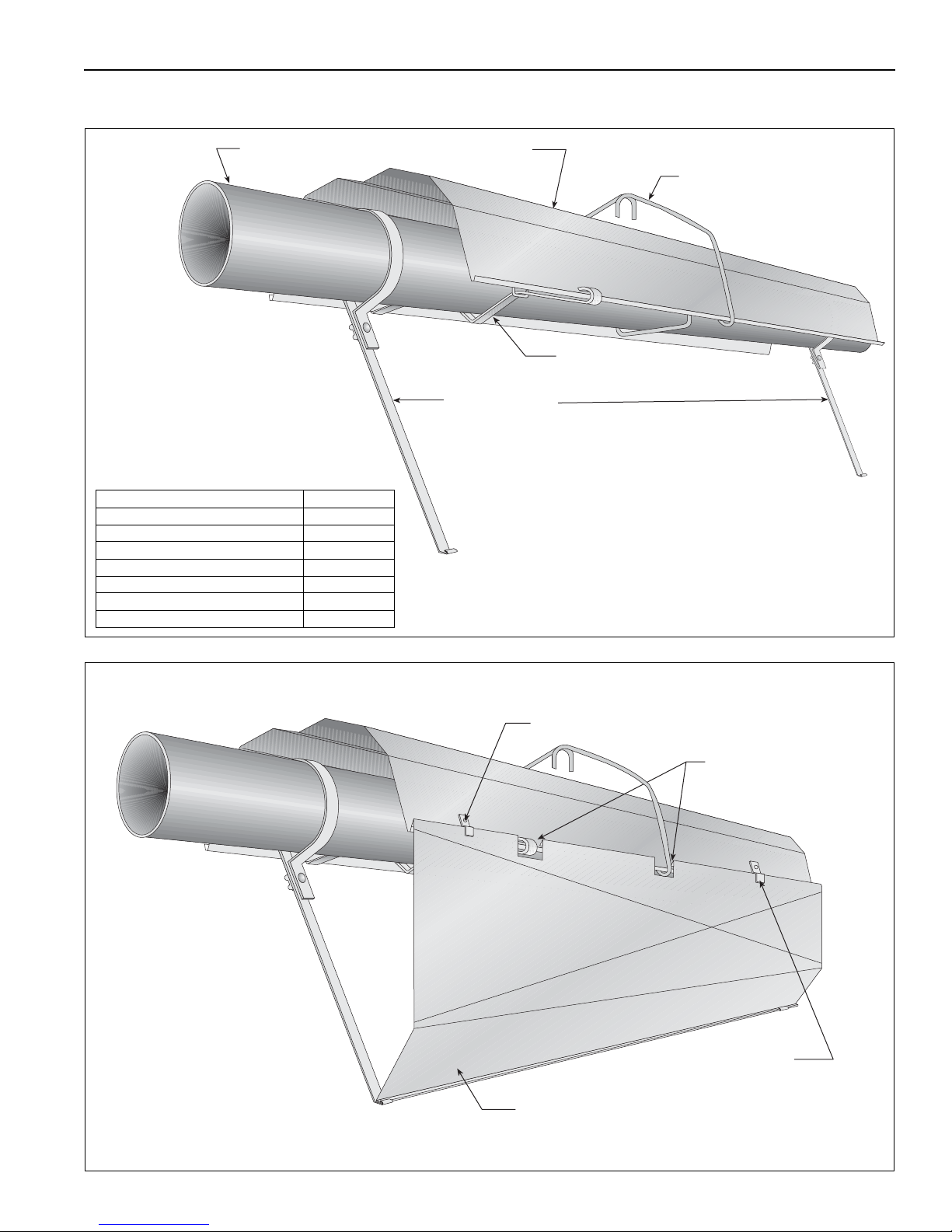
7.3 Reflector Side Extension
Reflector Side
Extension Bracket
(2 per Reflector)
Use additional supports
in high air movement
applications.
Tube and Reflector Hanger,
Wide Pattern
ReflectorTube
Reflector Support,
Wide Pattern
Description Part Number
Reflector Side Extension Package 02712700
Reflector Side Extension 01368000
Retainer Clips 02751200
Sheet Metal Screws 94118106
Order Separately
Reflector Side Extension 01329910
Cut relief notches for
supports and hangers.
Retainer Clip
(2 per side)
#8 x 3/8" Sheet Metal Screw
Reflector Side Extension
Step 7.3.1 Bracket Installation
SECTION 7: OPTIONAL H EATER ACCES SORIES
Step 7.3.2 Side Reflector Installation
27 of 71
Page 34
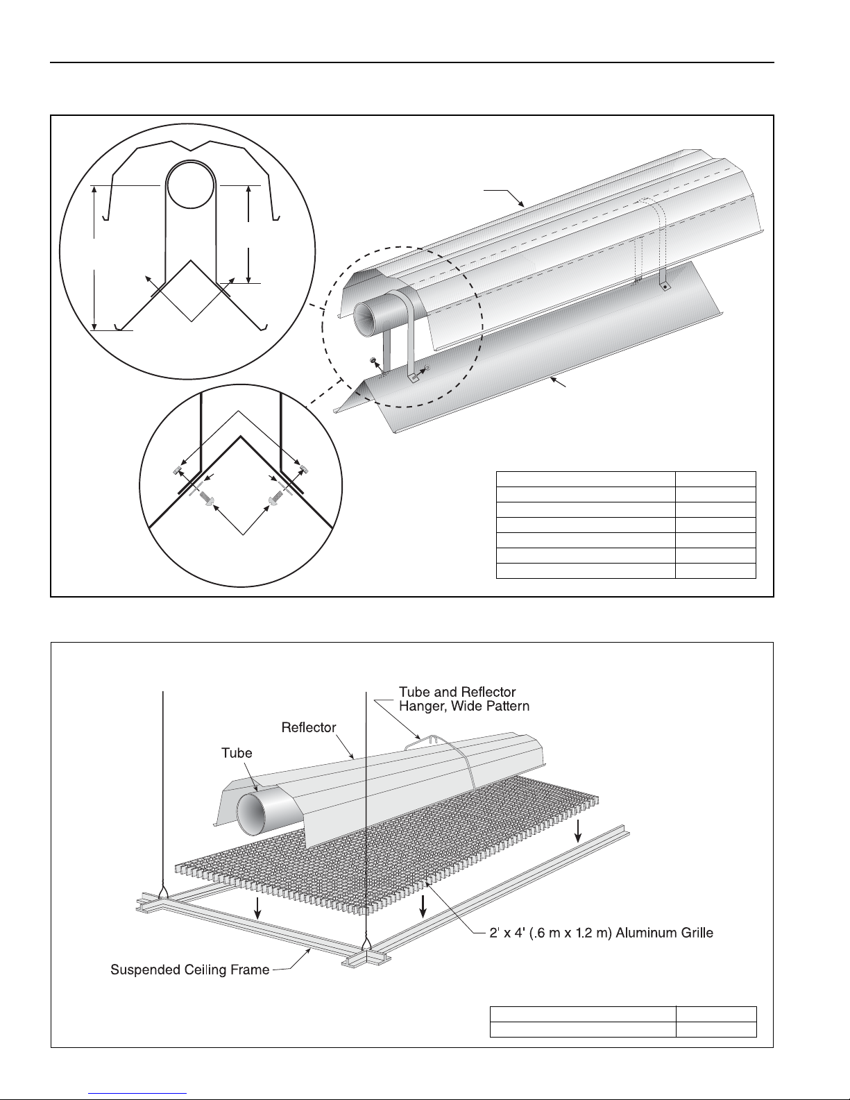
VM-SERIES INSTALLATION, OPERATION AND SERVICE MANUAL
12"
(30 cm)
Reflector
Lower Clearance Shield
17"
(43 cm)
Washers
Screws
Locknuts
Align Pilot Holes
Description Part Number
Lower Clearance Shield Package 01397501
Shield Support Strap 01397500
Lower Clearance Shield 8' 02793000
Locknut #8 92311400
Flat Washer #8 95310800
Screw #8 x 3/8" 93511406
Description Part Number
Aluminum Grille 2' x 4' 91407000
7.4 Lower Clearance Shield Installation
Step 7.4.1 Shield Support Strap Assembly
7.5 Two-Foot Decorative Grille Installation
Step 7.5.1 Grille Installation
28 of 71
Page 35
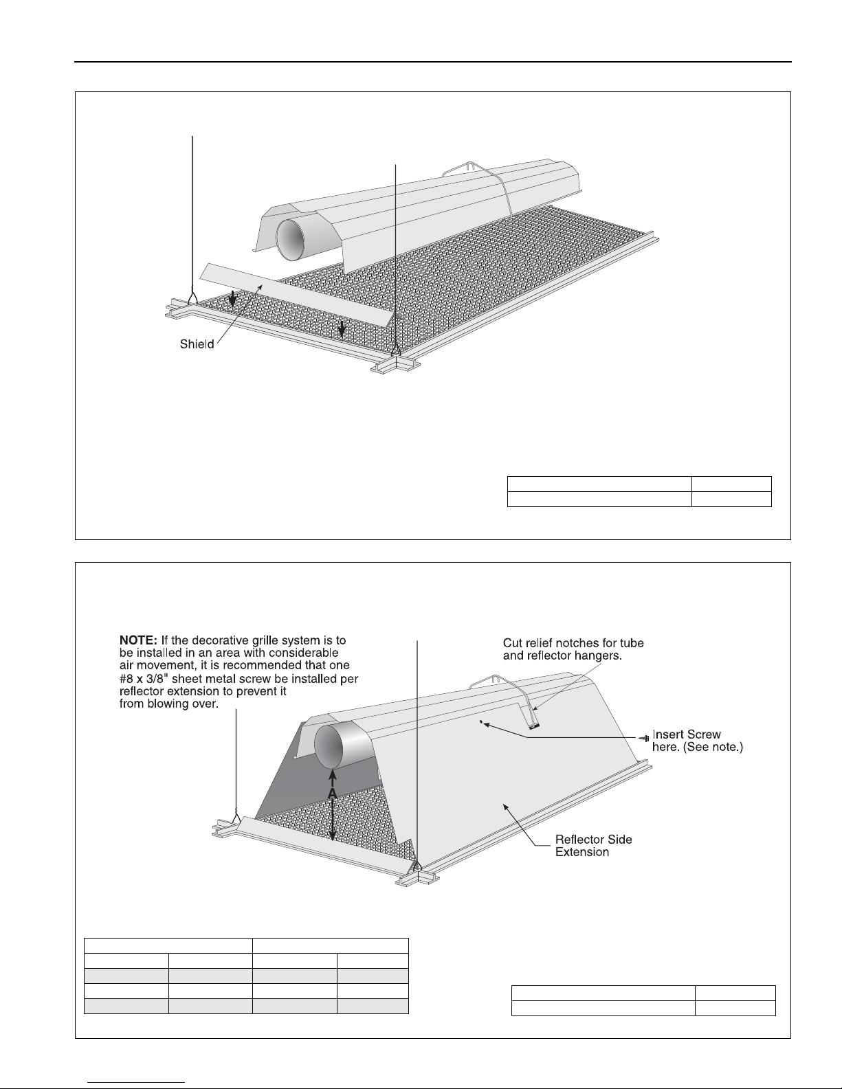
Step 7.5.2 Frame Shield Installation
Description Part Number
Deco Grille Shield 01365900
Distance "A" Extension
Minimum Maximum Part No. Width
2" (4 cm) 6" (15 cm) 01370408 8" (20 cm)
6" (15 cm) 10" (26 cm) 01370412 12" (30 cm)
10" (26 cm) 14" (37 cm) 01370416 16" (40 cm)
Description Part Number
Reflector Side Extension 01370412
SECTION 7: OPTIONAL H EATER ACCES SORIES
Step 7.5.3 Reflector Side Extension Installation for Decorative Grilles
29 of 71
Page 36
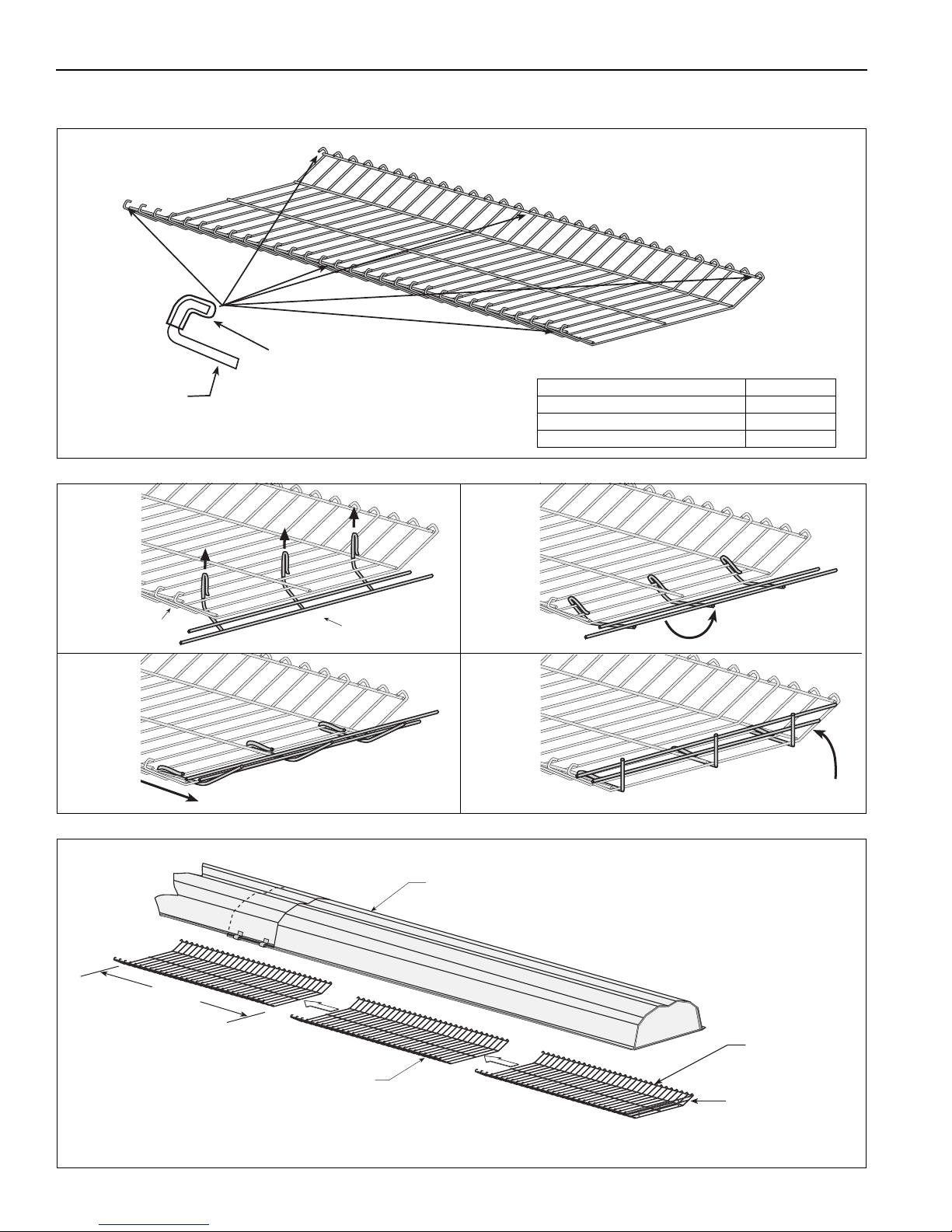
VM-SERIES INSTALLATION, OPERATION AND SERVICE MANUAL
Silicone Cap
Grille
Finger
Description Part Number
Grille Section 08050001
Grille End Cap 08050002
Silicone Cap 91915951-6P
Bend up 90°.
Pull outward.
Grille
Grille End Cap
A
B
C
D
Grille
Grille
End Cap
Reflector
Final Grille
Section
40"
(101 cm)
7.6 Protective Grille Installation
Step 7.6.1 Silicone Cap Installation
Step 7.6.2 Grille End Cap Installation
Step 7.6.3 Grille Installation
30 of 71
Page 37
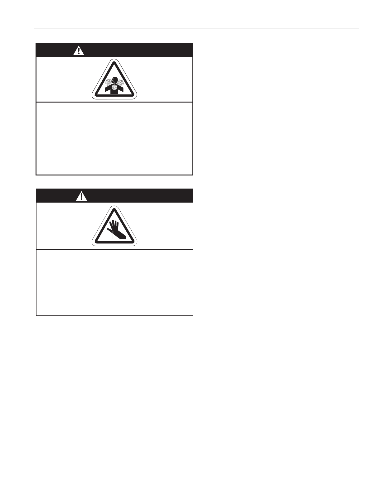
SECTION 8: VENTING
WARNING
Carbon Monoxide Hazard
Heaters installed unvented must be interlocked
with sufficient building exhaust.
Heaters must be installed according to the
installation manual.
Failure to follow these instructions can result
in death or injury.
WARNING
Cut/Pinch Hazard
Wear protective gear during installation,
operation and service.
Edges are sharp.
Failure to follow these instructions can result
in injury.
SECTION 8: VENTING
8.1 Venting
This heater must be vented in accordance with the
rules contained in this manual and with the following
national codes and any state, provincial or local
codes which may apply:
United States: Refer to National Fuel Gas Code
NFPA 54/ANSI Z223.1 - latest revision.
Canada: Refer to Natural Gas and Propane
Installation Code CSA B149.1 - latest revision.
In brooder installations, affix brooder ventilation wall
tag (P/N 91039300) adjacent to the heater
thermostat. In the absence of a thermostat, the wall
tag must be posted in a conspicuous location.
Exhaust end of heater will accept a 4
pipe using the vent adapter (P/N 90502700). To
prevent leakage of condensation, install the vent
adapter with the seam on top and seal the joint using
a high temperature silicone sealant.
" (10 cm) vent
Any portion of vent pipe passing through a
combustible wall must have an approved thimble
to conform with the above listed codes.
Vent pipe must be sloped downward away from the
burner 1/2'' (1 cm) for every 20' (6 m).
The heater may be individually vented or common
vented. When venting horizontally, a maximum of two
heaters can be commonly vented. See Page 33,
Section 8.9. When venting vertically, a maximum of
four heaters can be commonly vented. See Page 34,
Section 8.10.
The heater may also be installed unvented in certain
circumstances according to building
codes. Refer to the above codes and Page 31,
Section 8.2 for further information. Unvented
operation also requires compliance with the
clearances to combustibles given on Page 8, Figure
9.
The bottom of the vent or air intake terminal shall not
be located less than 1' (.3 m) above grade level.
The vent shall not terminate less than 7' (2.1 m)
above grade where located adjacent to public
walkways.
Vent terminal must be installed at a height sufficient
to prevent blockage by snow and building materials
protected from degradation by flue gasses.
Secure all joints with #8 x 3/8 sheet metal screws.
Seal all joints with high temperature silicone sealant.
Vent terminal must be beyond any combustible
overhang.
8.1.1 United States Requirements
Vent must terminate at least 3' (.9 m) above any
forced air inlet located within 10' (3.1 m).
Vent must terminate at least 4' (1.2 m) below,
4' (1.2 m) horizontally from, or 1' (.3 m) abov
door, operable window, or gravity air inlet into any
building.
8.1.2 Canadian Requirements
The vent shall not terminate within 6' (1.8 m) of a
mechanical air supply inlet to any building.
The vent shall not terminate within 3' (.9 m) of a
window or door that can be opened in any building,
any non-mechanical air supply inlet to any building,
or of the combustion air inlet of any other appliance.
8.2 Unvented Operation
Sufficient ventilation must be provided in the amount
of 4 cfm per 1000 Btu/h firing rate (United States); 3
cfm per 1000 Btu/h firing rate (Canada).
Use of optional outside combustion air is not
recommended with unvented heaters.
If exhaust fans are used to supply ventilation air, an
interlock switch must be used to prevent the heater
from coming on when the fans are off. This may be
done using a pressure s
witch.
ventilation
e any
31 of 71
Page 38
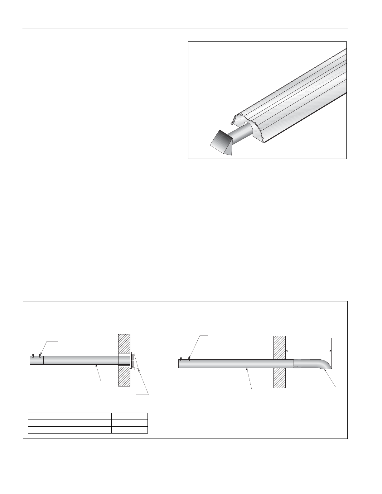
VM-SERIES INSTALLATION, OPERATION AND SERVICE MANUAL
4" (10 cm)
Single Wall Pipe
Vent Adapter
Vent Terminal
Combustible or
Non-Combustible Wall
Vent Adapter
18" (46 cm)
Min.
Vent Terminal
4" (10 cm) Single Wall Pipe
Non-Combustible Wall Only
SIDE VIEW
Description Part Number
Vent Terminal (Comb. Wall) 90502100
Vent Terminal 02537801-XX
8.3 Horizontal Venting
In noncombustible walls only, vent terminal
(P/N 02537801-1P) may be used.
For 4" (10 cm) vents in either combustible or
noncombustible walls, use Tjernlund VH1-4 (P/N
90502100) or equivalent, insulated vent terminal.
Follow the manufacturer's instructions for proper
installation.
For 6" (15 cm) common vents in either combustible
or noncombustible walls, use Tjernlund VH1-6 (P/N
90502101) or equivalent, insulated vent terminal.
Follow the manufacturer's instructions for proper
installation.
8.4 Vertical Venting
For 4" (10 cm), an approved vent cap
(P/N 90502300) must be used.
For 6" (15 cm) common vent, an approved vent cap
(P/N 90502302) m
ust be used.
For common vertical venting of more than two
heaters, See Page 34, Section 8.10.
A vent shall not extend less than 2' (.6m) above the
highest point where it passes through a flat roof of a
building.
8.5 Unvented Operation Tube Termination
Turndown type vent terminal with a screen must be
installed at the exhaust end of the tube. Vent terminal
design shall not incorporate backdraft flap.
8.7 Horizontal Ventilation 4" (10 cm) Pipe
FIGURE 17: Tube Termination
8.6 Length Requirements
The maximum vent length allowed is 45' (13.7 m).
The maximum outside air supply duct length allowed
is 45' (13.7 m).
The total vent length, plus outside air duct length and
any extensions to minimum heat exchanger lengths,
cannot exceed 65' (19.8 m).
Vent length should be limited to less than 20' (6 m).
If using extended heater lengths or vent lengths
greater than 20' (6 m), condensation will form in the
vent pipe. Insulation and additional sealing measu
res
(high temperature silicone at all seams) are required.
Optional heat exchanger beyond minimum lengths
are considered as vent length for length
determination.
Subtract 15' (4.6 m) of maximum allowed vent or duct
length per vent elbow if more than two are used.
32 of 71
Page 39
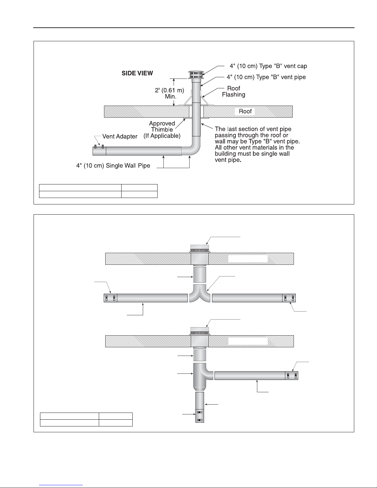
8.8 Vertical Ventilation 4" (10 cm) Pipe
Description Part Number
Vent Cap 4" (10 cm) 90502300
4" (10 cm) Single Wall Pipe
Outside Wall
Vent Adapter
Sweeping 'T'
Connection
Sweeping 'Y'
Connection
Outside Wall
6" (15 cm) Single Wall Pipe
Vent Terminal
Tjernlund VH1-6 or Equivalent
Outside Wall
4" (10 cm) Single Wall Pipe
Vent Adapter
Vent Terminal
Tjernlund VH1-6 or Equivalent
Vent Adapter
Vent Adapter
TOP VIEW
4" (10 cm) Single Wall Pipe
6" (15 cm) Single Wall Pipe
Description Part Number
Vent Terminal 6" (15 cm) 90502101
SECTION 8: VENTING
8.9 Common Side Wall Venting
Requirements:
• Maximum of two heaters can be commonly
vented through a side wall.
• Heaters must be of the same BTU output.
• Heaters must be controlled by a common
thermostat.
33 of 71
Page 40
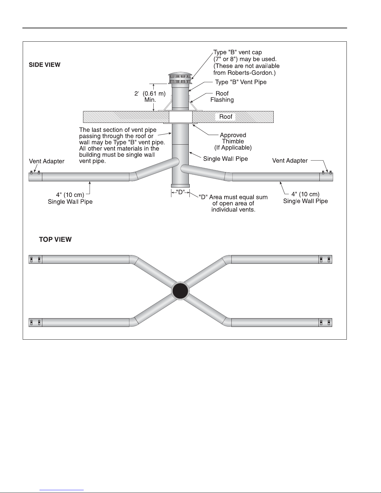
VM-SERIES INSTALLATION, OPERATION AND SERVICE MANUAL
8.10 Common Vertical Venting
Requirements:
• Maximum of four heaters can be commonly vented
through the roof.
• Heaters must be of the same BTU output.
• Heaters must be controlled by a common
thermostat.
• Connections to a common stack must be
positioned to avoid direct opposition between
streams of combustion gases.
34 of 71
Page 41
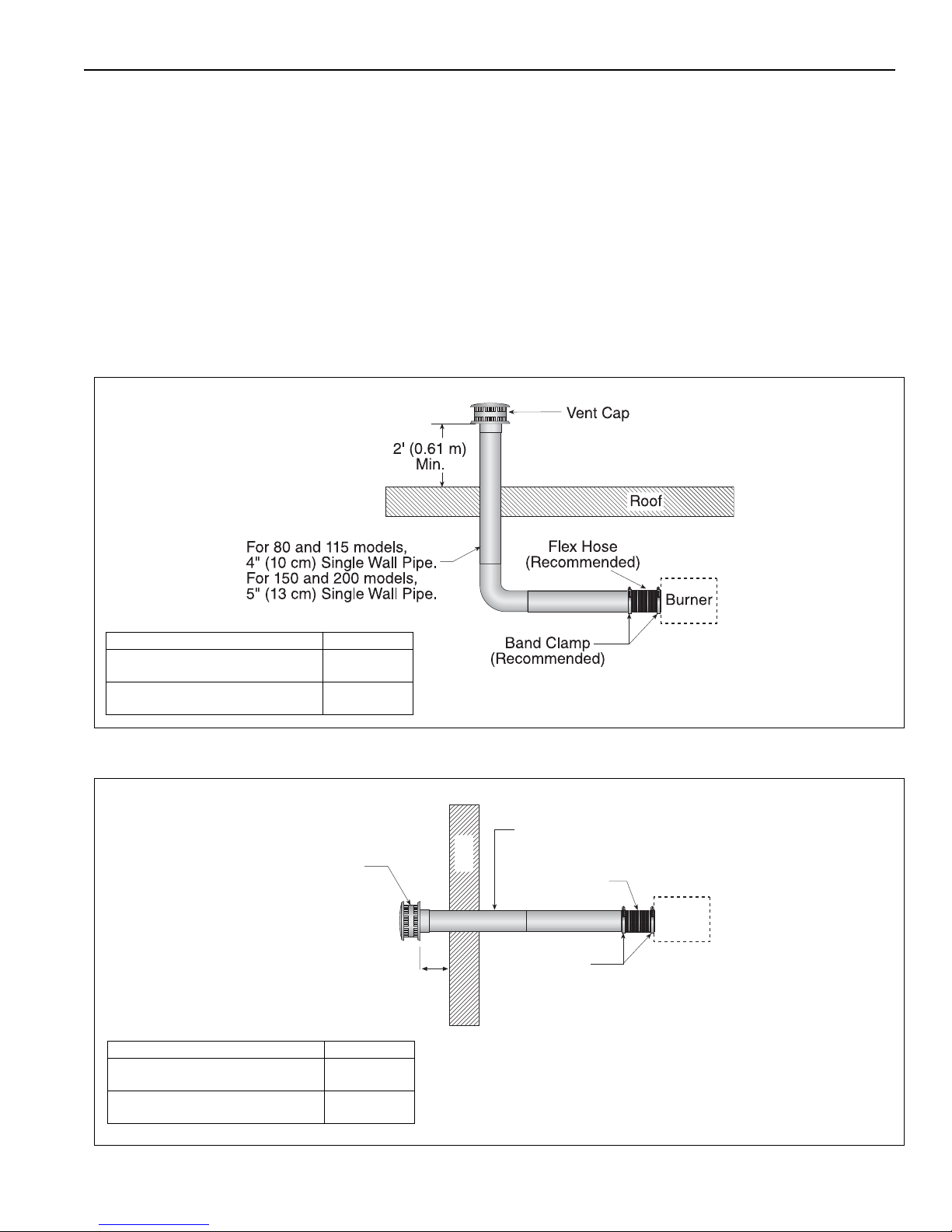
8.11 Outside Combustion Air Supply
Description Part Number
Vent Cap 4" (10 cm) for 80,000 Btu/h
and 115,000 Btu/h models
90502300
Vent Cap 5" (13 cm) for 150,000 Btu/h
and 200,000 Btu/h models
90502301
SIDE VIEW
Band Clamp
(Recommended)
Flex Hose
(Recommended)
Vent Cap
Wall
For 80 and 115 models,
4" (10 cm) Single Wall Pipe.
For 150 and 200 models,
5" (13 cm) Single Wall Pipe.
Burner
4"
(10 cm)
Min.
SIDE VIEW
Description Part Number
Vent Cap 4" (10 cm) for 80,000 Btu/h
and 115,000 Btu/h models
90502300
Vent Cap 5" (13 cm) for 150,000 Btu/h
and 200,000 Btu/h models
90502301
IMPORTANT: If the building has a slight negative
pressure or corrosive contaminants such as
8.11.1 Length Requirements
Follow the constraints listed on Page 32, Section 8.6.
halogenated hydrocarbons are present in the air, an
outside combustion air supply to the heater is
required. Seal all combustion air pipe joints.
The air supply duct may have to be insulated to
prevent condensation on the outer surface. The
outside air terminal must not be more than 1' (31 cm)
above the vent terminal.
Use of optional outside combustion air is not
recommended with unvented heaters.
8.11.2 Vertical Outside Air Supply for Single Heater Installation
SECTION 8: VENTING
8.11.3 Horizontal Outside Air Supply for Single Heater Installation
35 of 71
Page 42
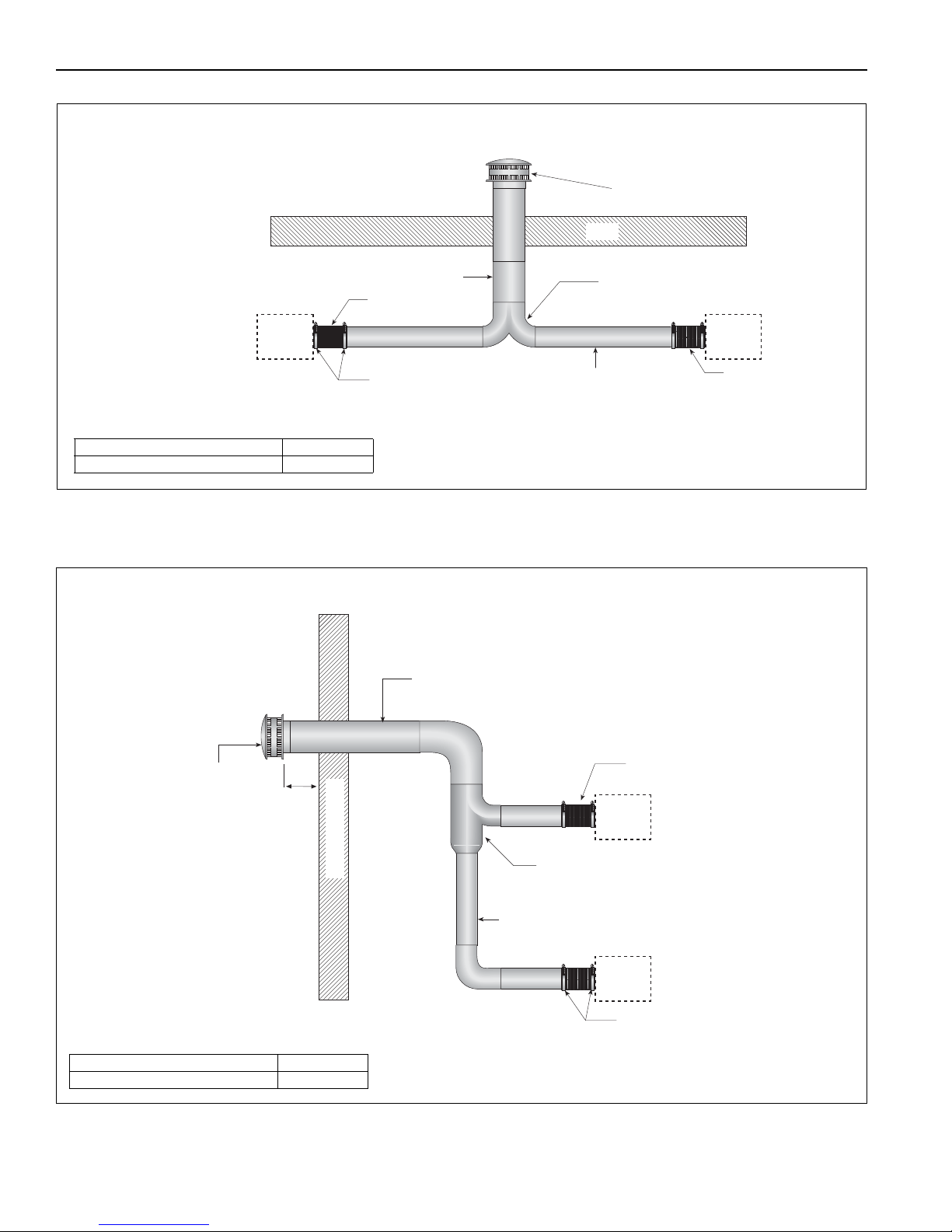
VM-SERIES INSTALLATION, OPERATION AND SERVICE MANUAL
Sweeping 'T'
Connection
For 80 and 115 models, 6" (15 cm) Single Wall Pipe.
For 150 or 200 models, 7" (18 cm) Single Wall Pipe.
Vent Cap
Band Clamp
(Recommended)
BurnerBurner
Flex Hose
(Recommended)
Flex Hose
(Recommended)
Roof
For 80 and 115 models, 4"
(10 cm) Single Wall Pipe.
For 150 or 200 models, 5"
(13 cm) Single Wall Pipe.
Description Part Number
Vent Cap 6" (15 cm) 90502302
SIDE VIEW
Sweeping 'Y'
Connection
Vent Cap
Outside Wall
For 80 or 115 models, 4" (10 cm)
Single Wall Pipe. For 150 and 200
models, 5" (13 cm) Single Wall Pipe.
Flex Hose
(Recommended)
Band Clamp
(Recommended)
Burner
Burner
4"
(10 cm)
Min.
For 80 or 115 models, 6" (15 cm)
Single Wall Pipe. For 150 and 200
models, 7" (18 cm) Single Wall Pipe.
Description Part Number
Vent Cap 6" (15 cm) 90502302
TOP VIEW
8.11.4 Vertical Outside Air Supply for Double Heater Installation
Requirements:
• Heaters must be controlled by a common thermostat.
8.11.5 Horizontal Outside Air Supply for Double Heater Installation
Requirements:
• Heaters must be controlled by a common thermostat.
36 of 71
Page 43
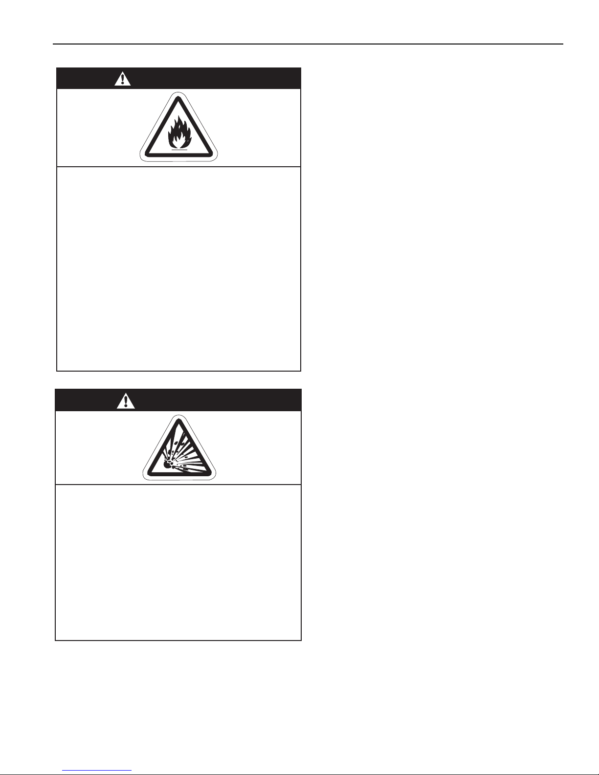
SECTION 9: GAS P IPING
WARNING
Explosion Hazard
Leak test all components of gas piping
before operation.
Gas can leak if piping is not installed
properly.
Do not high pressure test gas piping with
heater connected.
Failure to follow these instructions can result
in death, injury or property damage.
SECTION 9: GAS PIPING
WARNING
Fire Hazard
Tighten gas hose fittings to connect gas
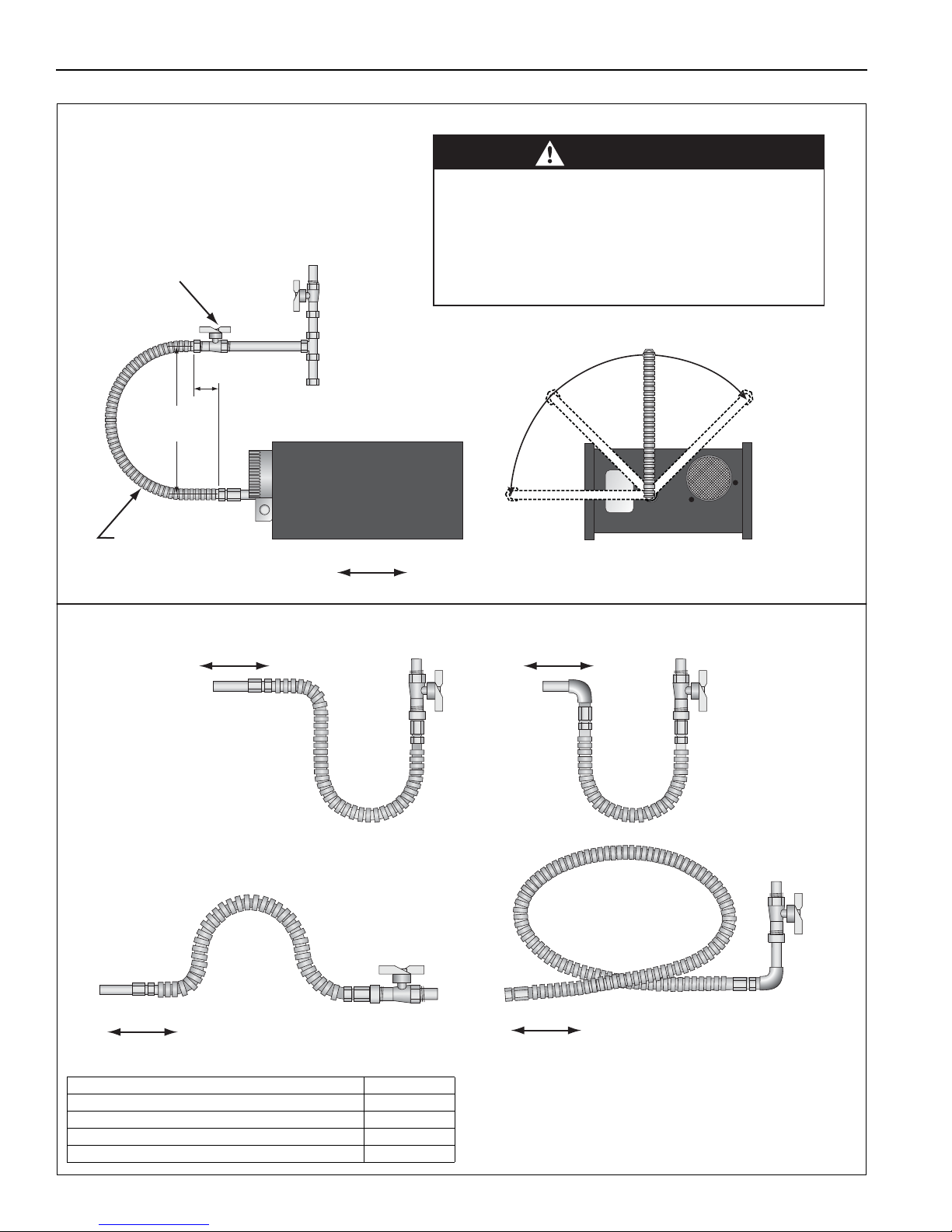
supply according to Figure 21.
Gas hose can crack when twisted.
Gas hose moves during normal operation.
Use only 36" (91 cm) long connector of 1/2" or
3/4" nominal ID.
Connector supplied with heater for U.S.
models (not with Canadian models).
Failure to follow these instructions can result
in death, injury or property damage.
There is an expansion of the tube with each firing
cycle. This will cause the burner to move with respect
to the gas line. This can cause a gas leak resulting in
an unsafe condition if the gas connection is not made
in strict accordance with Figure 18.
Meter and service must be large enough to handle all
the burners being installed plus any other connected
load. The gas line which feeds the system must be
large enough to supply the required gas with a
maximum pressure drop of 1/2" wc When gas piping
is not included in the layout drawing, the local gas
supplier will u
Gas lines must meet applicable codes:
United States: The Flexible Stainless Steel Gas
Hose (US models) supplied with the heater is
certified per the Standard for Connectors for Gas
Appliances, ANSI Z21.24/CSA 6.10 - latest revision.
Canada: The Rubber Type 1 Gas Hose (Canadian
models) optional with the heater is certified as being
in compliance with the Standard for Elastomeric
Composite Hose and Hose Couplings for Conducting
Propane and Natural Gas, CAN/CGA 8.1 - Latest
revision.
• Check the pipe and tubing ends for leaks
before placing heating equipment into service. When checking for gas leaks, use a soap
and water solution; never use an open flame.
sually help in planning the gas piping.
Install the gas hose as shown in Figure 18. The gas
hose accommodates expansion of the heating
system and allows for easy installation and service of
the burner. Before connecting the burners to the
supply system, verify that all high pressure testing of
the gas piping has been completed.
37 of 71
Page 44
VM-SERIES INSTALLATION, OPERATION AND SERVICE MANUAL
Shut-Off Valve (included with gas hose) must
be parallel to burner gas inlet. The 3" (8 cm)
displacement shown is for the cold condition.
This displacement may reduce when the
system is fired.
CORRECT POSITIONS
Horizontal
45°
End View
Vertical
(as shown left)
Alternate
positions
okay
Flexible Gas Hose
36" (91 cm) length
3" (8 cm)
max. displacement
Side View
Heater Movement
12"
(30 cm)
CAUTION
Product Damage Hazard
Hold gas nipple securely with pipe wrench
when attaching gas hose.
Failure to follow these instructions can result
in product damage.
INCORRECT POSITIONS (WRONG INSTALLATION)
Heater Movement
Heater Movement
Heater Movement Heater Movement
Description Part Number
1/2" Flexible Stainless Steel Gas Hose (US Models) 91412200
3/4" Flexible Stainless Steel Gas Hose (US Models) 91412204
1/2" Rubber Type 1 Gas Hose (Canadian Models) 91412206
3/4" Rubber Type 1 Gas Hose (Canadian Models) 91412207
FIGURE 18: Gas Connection with Flexible Gas Hose
38 of 71
Page 45
SECTION 10: WIRING
DANGER
Electrical Shock Hazard
Disconnect electric before service.
Heater must be properly grounded.
Failure to follow these instructions can result
in death or electrical shock.
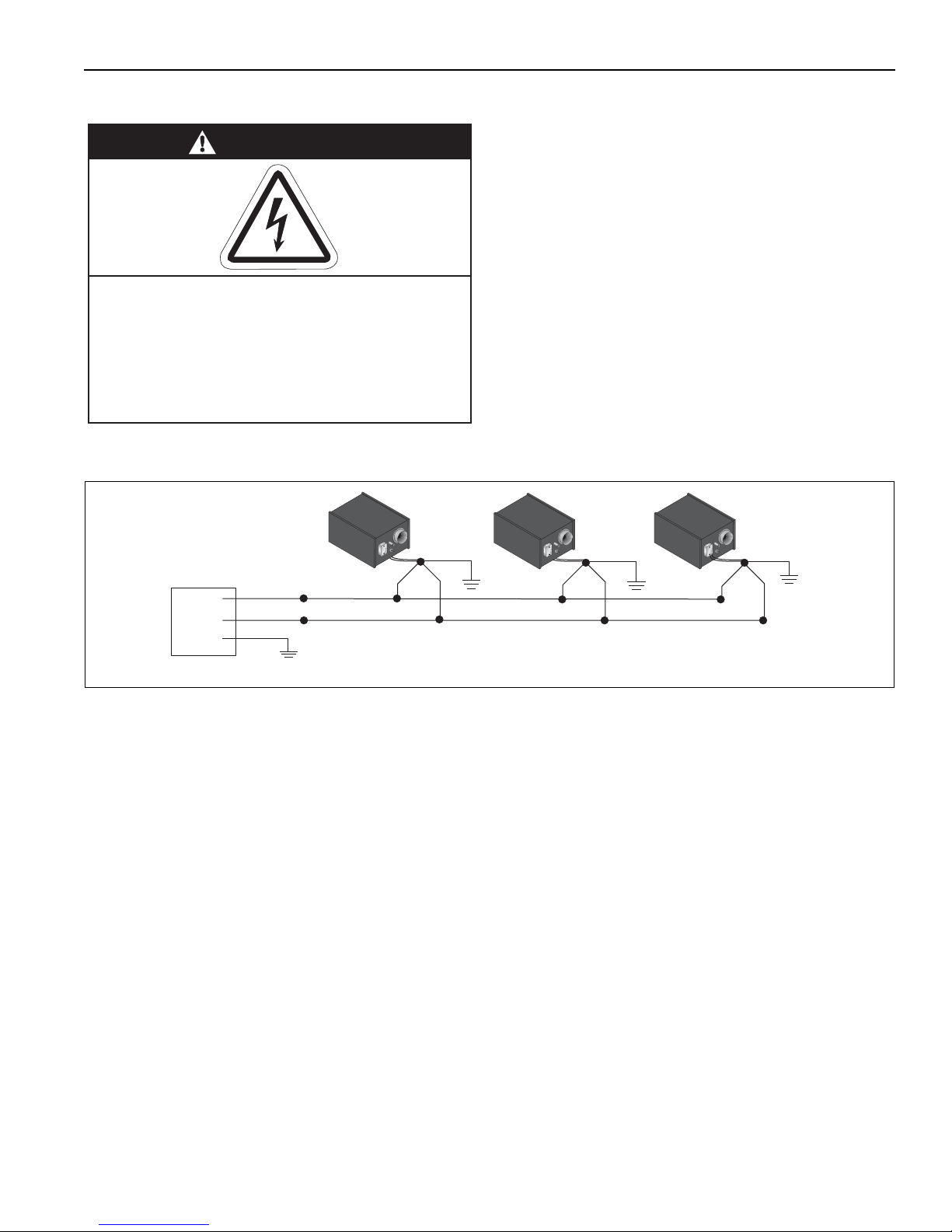
Gnd.
120 V-60 Hz
Supply Circuit
H
N
H
N
L1
L2
Gnd.
Gnd.
Burner 2
Burner 3
Gnd.
Burner 1
H
N
NOTE: The burners must have an uninterrupted 120 V, 60 Hz, 1 Ø power supply.
All burners are powered by a circuit(s) seperate from the brooder controller outputs.
SECTION 10: WIRING Heater must be grounded in accordance with
applicable codes: United States: refer to National
Electrical Code
®
NFPA 70 - latest revision
Canada: refer to Canadian Electrical Code, CSA
C22.1 Part I - latest revision.
If any of the original internal wiring must be replaced,
it must be replaced with wiring materials having a
temperature rating of at least 105°C and 600 Volts.
10.1 Heater Wiring for use with Brooder Contoller
The heater will automatically modulate when
connected to an output relay on a brooder controller.
10.1.1 Line Voltage Power Wiring
All burners are powered by a circuit(s) separate from
the brooder controller outputs. The burners must
have an uninterrupted 120 V, 60 Hz, 1 Ø power
supply.
FIGURE 19: Line Voltage Power Wiring
39 of 71
Page 46
VM-SERIES INSTALLATION, OPERATION AND SERVICE MANUAL
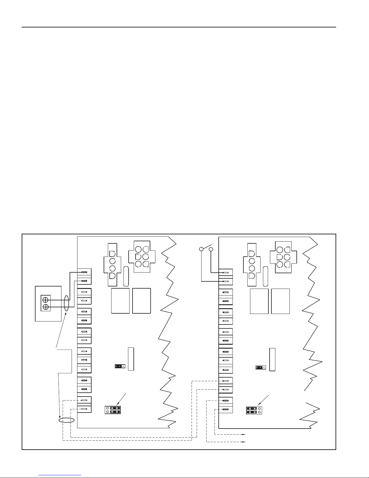
*OPTIONAL
SWITCH
SATELLITE HEATER CONTROL
J10 JUMPER POSITION
SHOWS "SATELLITE" DESIGNATION.
MODULATION CONTROL WIRING
TO ADDITIONAL SATELLITE
HEATER CONTROL TERMINALS
T28 AND T29.
MODULATION CONTROL WIRING
TO SATELLITE HEATERS
CENTRAL HEATER CONTROL
T31
T29
T19
T18
T16
T14
T27
T25
T30
T28
T17
T15
T13
T26
T24
T31
T29
T19
T18
T16
T14
T27
T25
T30
T28
T17
T15
T13
T26
T24
J10
W
R
-+
-
+
-+
OUT
RATE
FIRING
IN
RATE
FIRING
EXT. POT
GND
WIPER
HIGH
GND
BAR
SLIDE
GND
THERMISTOR
INPUT
ANALOG
THERMOSTAT
J10
W
R
-+
-
+
-+
OUT
RATE
FIRING
IN
RATE
FIRING
EXT. POT
GND
WIPER
HIGH
GND
BAR
SLIDE
GND
THERMISTOR
INPUT
ANALOG
THERMOSTAT
Brooder Controller
Output Terminal
Connection
(Dry contact only,
the controller must
not provide any power
to the R and W circuit.)
J10 JUMPER POSITION
SHOWS "CENTRAL"
DESIGNATION AND
"THERMOSTAT"
CONTROL METHOD.
Do not run
low voltage
control wiring
in conduit with
line voltage wiring.
10.1.2 Brooder Control Wiring
The heater outputs on the brooder controller will act
as the ON/OFF switch in the control circuit. The R
and W terminals (T24 and T25) on the heater control
board are wired to the heater output terminal on the
brooder controller. If the brooder controller outputs
provide line voltage output, a contactor must be
installed between the brooder controller and the
heater R and W terminals (T24 and T25). Power
must not be supplied to the “thermostat” (R and W)
circuit. The brooder controller must only provide the
opening and closing (dry contact) of the “thermostat”
(R and W) circuit. The heater that is wired to the
brooder output terminals will be designated as a
“central” heater. If there are multiple heaters in a
heating zone, the control wiring for all of the other
heaters in the zone will be wired in series (daisychain) from the “central” heater’s “firing rate out”
terminals (T30 and T31). See Figure 2. The jumpers
on the J10 pin block on the heater control board must
set by the installer as shown in Figure 2. The
“central” heater will have both j
umpers on the J10 pin
block on the right-most pins as shown if Figure 2.
The satellite heaters will have the J10 pin jumpers
set on the left-most pins.
10.1.3 Operation
During the heater operation, the heater will
automatically modulate based on the brooder
controller’s ON/OFF output timing and history using
an algorithm programmed into the heater’s control
board. The “central” heater will determine the
appropriate heater burn rate and any satellite heaters
will modulate to the same burn rate based on the
central heater’s commands.
NOTE: During the cycling of the heaters, the heaters
may still be operating even though the brooder
controller may not be calling for heat. This is normal
operation of the modulating heater. After satisfying
the required temperature, the heater will continue to
run at a lower burn rate to maintain the temperature
as close to the temperature setpoint as possible.
The heater will completely turn off once it modulates
the burn rate to the lowest setting.
FIGURE 20: Low Voltage Brooder Control Wiring
40 of 71
Page 47
SECTION 10: WIRING
MODULATION CONTROL WIRING
TO SATELLITE HEATERS
CENTRAL HEATER CONTROL
OFF
ON
-LCD++FAN-SEN
ZONE SENSOR
SET
J10
W
R
-
+
-
+
-+
OUT
RATE
FIRING
IN
RATE
FIRING
EXT. POT
GND
WIPER
HIGH
GND
BAR
SLIDE
GND
THERMISTOR
INPUT
ANALOG
THERMOSTAT
T31
T29
T19
T18
T16
T14
T27
T25
T30
T28
T17
T15
T13
T26
T24
MODULATION CONTROL WIRING
TO ADDITIONAL SATELLITE
HEATERS CONTROL TERMINALS
T28 and T29.
*OPTIONAL
SWITCH
SATELLITE HEATER CONTROL
J10
W
R
-
+
-
+
-+
OUT
RATE
FIRING
IN
RATE
FIRING
EXT. POT
GND
WIPER
HIGH
GND
BAR
SLIDE
GND
THERMISTOR
INPUT
ANALOG
THERMOSTAT
T31
T29
T19
T18
T16
T14
T27
T25
T30
T28
T17
T15
T13
T26
T24
A
B
AB
* Separate on/off switch is optional for
"satellite" heaters (install at user level). On/
Off switch is used to disable heater operation
or reset a heater that is in "lockout" mode. If
on/off switch is not desired, leave jumper wire
between R and W terminals in place.
Description Part Number
Zone Sensor, 40° - 75° 10081530
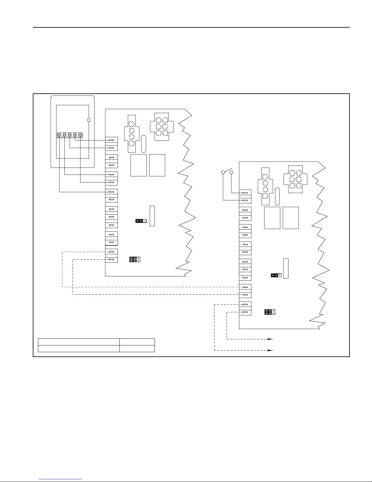
10.2 Standard Heater Configuration
From the factory, the heater is configured for zone
sensor control. Connect zone sensor to the heater
control as shown on Page 41, Figure 21.
If additional heaters are in the same heating zone,
FIGURE 21: Zone Sensor Wiring Diagram
control wiring must be installed between the heaters’
controls as shown on Page 41, Figure 21.
For additional details or for use with heat demand
control devices other than the zone sensor, see Page
42, Section 10.3 through Page 50, Section 10.5.9.
41 of 71
Page 48
VM-SERIES INSTALLATION, OPERATION AND SERVICE MANUAL
10.3 Central and Satellite Heaters (Zoning Capability)
The heater can be configured so that several heaters
within the same heating zone will modulate
simultaneously with connection to a single heat
demand control device. The heat demand control
device (See Page 46, Section 10.5) will be wired
directly to a single heater configured as the central
heater. The remaining heaters in the zone will be
configured as satellite heaters and will modulate
based on control signaling from the central heater.
Zoning capability allows any CTH3-Series heater
(regardless of input) to modulate based on the signal
from the central heater. During modulation, each
satellite heater will operate at the same percentage
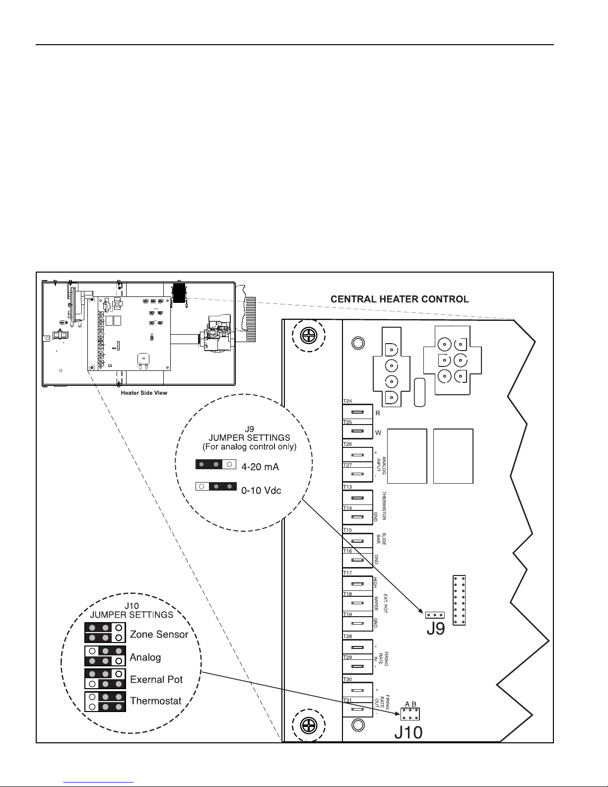
10.3.1 Central Heater Configuration
Central heater configuration is set by positioning of
jumpers on pin blocks (J10 and J9) located on the
control inside the heater compartment, See Page 42,
Figure 22. Jumper position on J10 shown in Figure
22, will configure heater as a central heater and at
the same time configure the heater for the desired
heat demand device (zone sensor, thermostat,
analog input, or 10K Ohm pot.). If j
positioned for "analog", jumper on J9 must be
positioned for either 0-10 Vdc or 4-20 mA. If jumpers
on J10 are not positioned for "analog", the J9 jumper
may be left alone.
of full rated input as the central heater.
FIGURE 22: Central Heater Jumper Settings
umpers on J10 are
42 of 71
Page 49
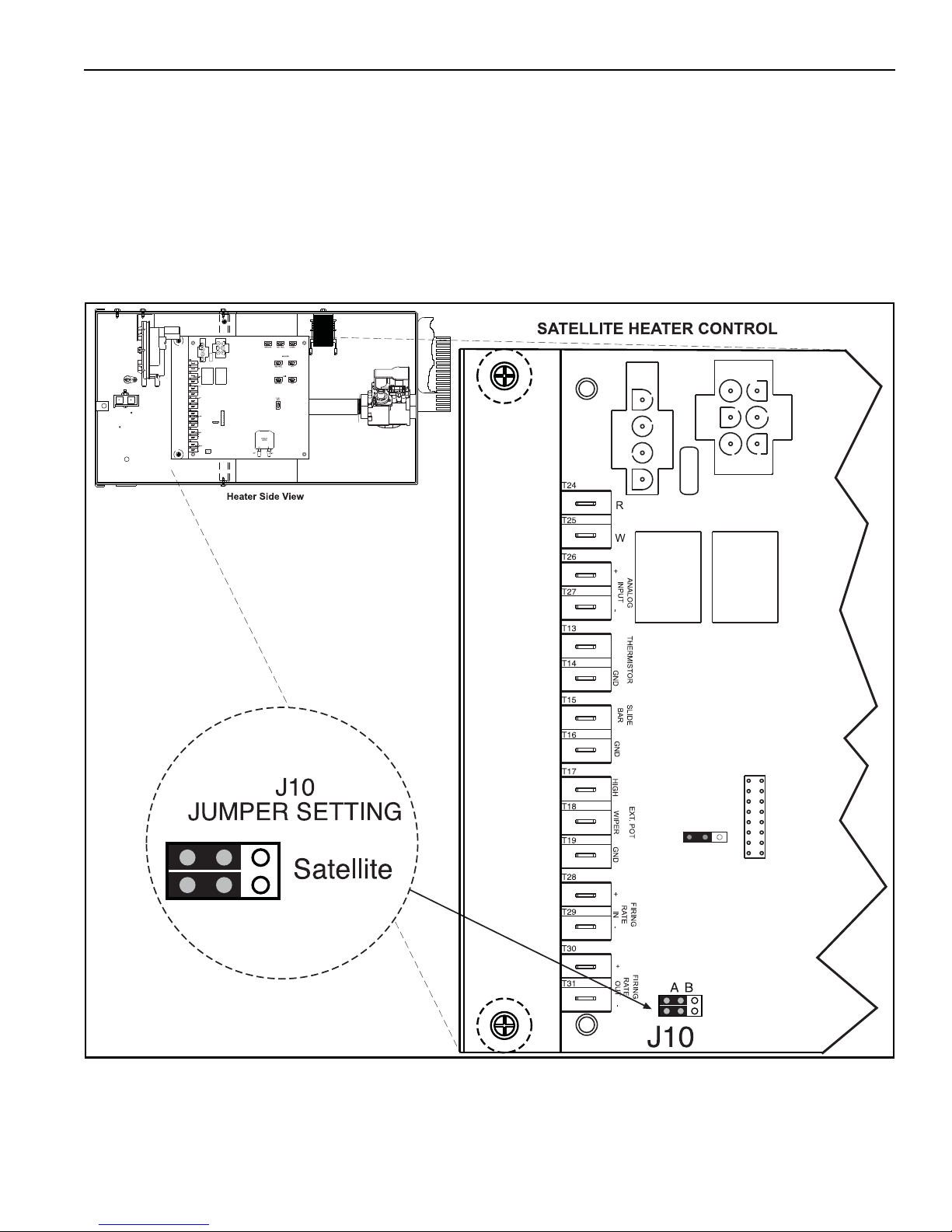
10.3.2 Satellite Heater Configuration
Satellite heater configuration is set by positioning of
jumpers on pin block J10 located on the control board
inside the heater compartment, See Page 43, Figure
23. Jumper position on J10, shown on Page 43,
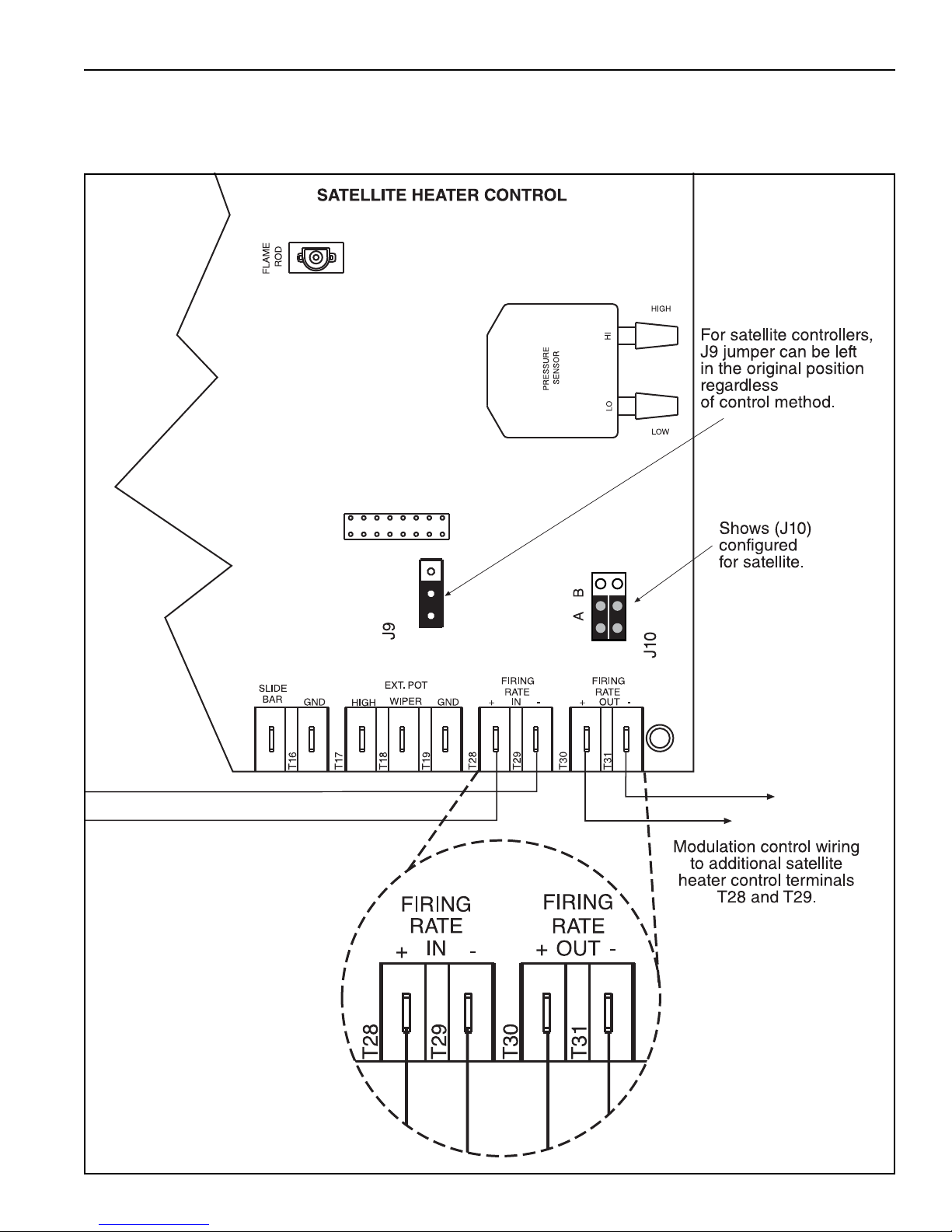
Figure 23 will configure heater as a satellite heater.
(The jumper position for satellite is the same as the
jumper position of a central heater using a zone
sensor). Jumper on J9 may be left alone.
FIGURE 23: Satellite Heater Jumper Setting
SECTION 10: WIRING
43 of 71
Page 50
VM-SERIES INSTALLATION, OPERATION AND SERVICE MANUAL
CENTRAL HEATER CONTROL
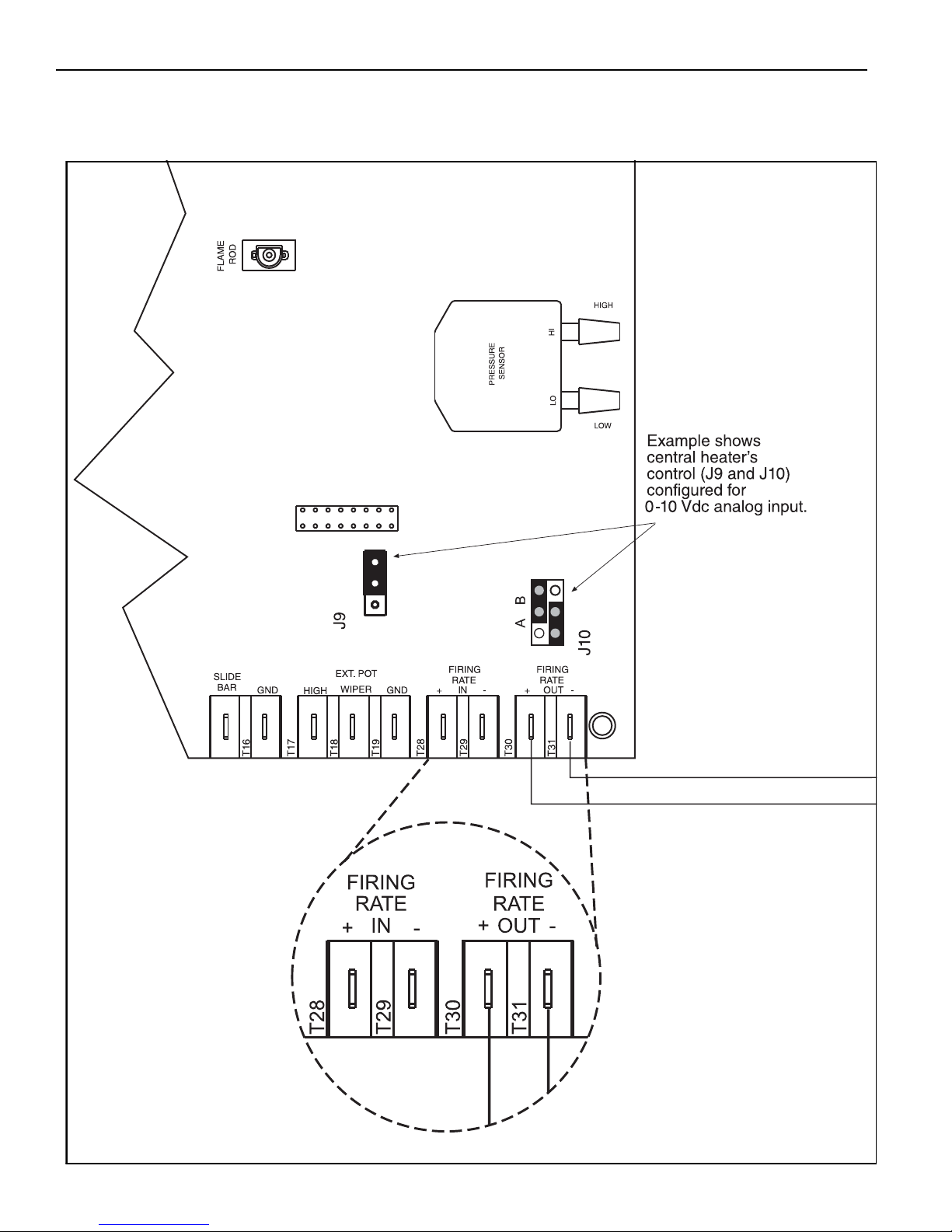
10.4 Communication Wiring within a Zone of Heaters
Satellite heaters will be wired in series to the central
heater via low voltage control wiring.
Communication wiring uses the T28-T31 terminals
on the control, see Page 44, Figure 24.
FIGURE 24: Communication Wiring within a Zone of Heaters
44 of 71
Page 51
SECTION 10: WIRING
10.4 Communication Wiring within a Zone of Heaters (continued)
Satellite heaters will be wired in series to the central heater via low voltage control wiring.
Communication wiring uses the T28-T31 terminals on the control, See Page 44 through Page 45, Figure 24.
FIGURE 24: Communication Wiring within a Zone of Heaters (continued)
45 of 71
Page 52
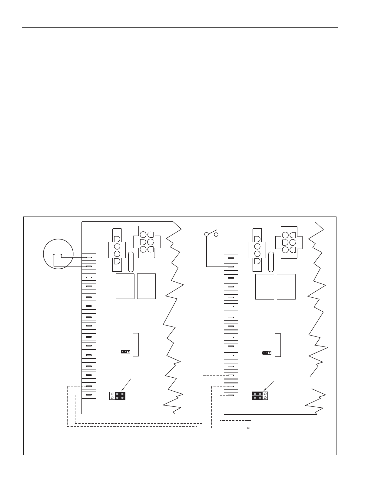
VM-SERIES INSTALLATION, OPERATION AND SERVICE MANUAL
*OPTIONAL
SWITCH
SATELLITE HEATER CONTROL
J10 JUMPER POSITION
SHOWS "SATELLITE" DESIGNATION.
MODULATION CONTROL WIRING
TO ADDITIONAL SATELLITE
HEATER CONTROL TERMINALS
T28 AND T29.
MODULATION CONTROL WIRING
TO SATELLITE HEATERS
CENTRAL HEATER CONTROL
T31
T29
T19
T18
T16
T14
T27
T25
T30
T28
T17
T15
T13
T26
T24
T31
T29
T19
T18
T16
T14
T27
T25
T30
T28
T17
T15
T13
T26
T24
RW
T
J10
W
R
-+
-
+
-+
OUT
RATE
FIRING
IN
RATE
FIRING
EXT. POT
GND
WIPER
HIGH
GND
BAR
SLIDE
GND
THERMISTOR
INPUT
ANALOG
THERMOSTAT
J10
W
R
-+
-
+
-+
OUT
RATE
FIRING
IN
RATE
FIRING
EXT. POT
GND
WIPER
HIGH
GND
BAR
SLIDE
GND
THERMISTOR
INPUT
ANALOG
THERMOSTAT
J10 JUMPER POSITION
SHOWS "CENTRAL"
DESIGNATION AND
"THERMOSTAT"
CONTROL METHOD.
* Separate on/off switch is optional for "satellite" heaters (install at user level).
On/Off switch is used to disable heater operation or reset a heater that is in "lockout" mode.
If on/off switch is not desired, leave jumper wire between R and W terminals in place.
10.5 Heat Demand Control Wiring
The heater input can be controlled by any one of the
following heat demand control devices (control
devices are wired to central heaters only):
10.5.1 Zone Sensor
The zone sensor (P/N 10081530) offers automatic
control of heater input. Heater(s) modulates based
on difference between sensed air temperature and
the temperature setpoint. Heater modulation in
response to air temperature changes is immediate.
Setpoint is adjusted with the slide bar adjustment at
the bottom of the sensor. ON/OFF switch (used to
disable heater operation or reset heater from lockout)
is located on the side of the sensor. See Page 41,
Figure 21 for wiring details.
10.5.2 Thermostat
A thermostat offers automatic control of heater input.
The heater control is designed for use with a
standard 2-wire or 4-wire low voltage electronic
thermostat (not for use with thermostats that have a
heat anticipator). Typical wiring connects the R and
FIGURE 25: Thermostat Control Wiring Diagram
W wires to the heater control and does not connect
the Y (cooling) and G (fan) wires to the heater
control.
The heater can be used with thermostat, 24V (p/n
90425100) if set to 5 cycles per ho
ur. Any other
electronic thermostat without heat anticipator can be
used if set to 5 or 6 cycles per hour.
On the control, the T24 and T25 (R and W) terminals
supply 24 V to power an electronic thermostat. See
Page 46, Figure 25 for wiring details. Consult the
factory for other thermostat wiring configurations.
Heater(s) modulates based on heater and thermostat
cycle timing, history and desired setpoint by using a
pre-programmed algorithm. When using thermostat
control, heater modulation response to rapid air
temperature change is not immediate. Thermostat
control is not recommended for use in areas with
frequent or high air changes.
It is important to note that during normal operation,
heater cycle continues beyond meeting thermostat
setpoint.
46 of 71
Page 53

10.5.3 Analog Signal Modulating Thermostat (P/N
90425105)
A programmable, 7-day programming, modulating
thermostat can be installed to supply an analog (420mA) or (2-10Vdc with 500 Ohm resistor) control
signal to dictate the heater(s) firing rate. The
thermostat shall energize the T24 and T25 (R and
W) terminals. For thermostat wiring, See Page 51,
Figure 28 and Page 52, Figure 29. Optional room
sensors (P/N 10081520) and outdoor air sensors
(P/N 10081521) are available.
Room temperature averaging networks can be
created with up to nine room sensors (P/N
10081520). Refer to thermostat installation
instructions for wiring.
10.5.4 Analog Signal Modulating Thermostat with
®
LonWorks
If LonWorks
Communication (P/N 90425104)
®
communication is required, a
modulating thermostat can be installed to supply an
analog (4-20mA or 2-10Vdc) signal to control the
heater(s) firing rate. For thermostat wiring, See Page
51, Figure 28 and Page 52, Figure 29. Optional room
sensors (P/N 10081520) and outdoor air sensors
(P/N 10081521) are available for this thermostat, as
well.
The modulating thermostat with LonWorks
networking capability in a LonWorks
®
®
system.
provides
Communications port running at 78 kilobits per
second (kbs), this thermostat can be configured to
perform a variety of activities in which data is sent or
®
received on the LonWorks
. Information that can be
shared, viewed and modified with network includes:
• Current year, month, day, hour, minute, second.
• System Mode.
• Space Temperature
• Outdoor air temperature
• Current setpoint
• Occupied/Unoccupied schedule commands.
• Space Temperature
SECTION 10: WIRING
®
allow integral peer to peer BACnet
MS/TP LAN
network communications with configurable baud
rates and can easily integrate with a building
automation system.
MS/TP Wiring
Connect the -A terminal in parallel with all other -A
terminals on the network and the +B terminal in
parallel with other +B terminals.
10.5.6 Sequence of Operation for Modulating
Thermostats
The thermostat will control the heater(s) firing rate
based on the demand signal communicated from
thermostat program taking into account space
temperature. The thermostat will energize T25 (W)
terminal. At high heat, a demand signal will turn the
heater(s) on at maximum heater(s) firing rate. Once
the room temperature gets close to the thermostat
set point, then the thermostat program will slow the
heater(s) firing rate down until the room temperature
reaches the thermostat set point.
10.5.5 Analog signal Modulating with BACnet
Programmable Thermostat (P/N 90425109).
If BACnet
®
communication is required, a BACnet®
enabled modulating thermostat can be installed to
supply an analog output (0-10VDC) signal control to
dictate the heater(s) firing rate. For thermostat wiring,
See Page 53, Figure 30.
This thermostat is a flexible wall-mounted standalone control with combined controller/sensor.
Temperature sensing is standard with optional
humidity and motion sensing. BACnet
®
connections
®
47 of 71
Page 54
VM-SERIES INSTALLATION, OPERATION AND SERVICE MANUAL
10.5.7 Cable Termination
Tab le li s t s wiring types, sizes and distances for
modulating thermostat with LonWorks
®
communication (P/N 90425104), modulating
thermostat without communication (P/N 90425105)
®
and BACnet
programmable thermostat
(P/N 90425109)
Table 4:
Digital Outputs 18 AWG (0.75 sq mm) Standard thermostat wire 1000 ft (304 m)
Modulating Outputs 18 AWG (0.75 sq mm) 1 pair 500 ft (152 m)
Outdoor Air Temperature Sensor 18 AWG (0.75 sq mm) 1 pair 500 ft (152 m)
Remote Sensor 18 to 22 AWG
Power Wiring 18 to 14 AWG
LonWorks
MS/TP (P/N 90425109) 18 AWG (0.75 sq mm) Shield Belden cable #82760 or equivalent Refer to Thermostat Installation Guide
Cable Requirements
Wire Function Recommended Wire Size
(Minimum)
(0.75 to 0.34 sq mm)
®
(P/N 90424104 only)
( 0.75to 2.0 sq mm)
18 AWG
(0.75 sq mm) nonshielded
Specification or
Distance (Maximum)
Requirement
Twisted pair wire 1000 ft (304 m)
NEC Class II 140ºF (60°C ) Limited by line-loss effects on power
consumption.
1 pair Refer to E-bus Wiring Guide 74-2865
for maximum length and generic cable
specifications.
Power Requirements
Modulating thermostats require 24 volts, AC power.
10.5.8 Remote Analog Signal
Remote Analog Signal 0-10 Vdc or 4-20mA output
from external controller or Building Management
System (BMS) directly dictates heater(s) firing rate.
An algorithm must be programmed into the BMS or
external controller to receive zone air temperature
signals from its own temperature sensors and then
deliver an output signal to the heater(s) for the
desired firing rate.
For 0-10Vdc control of the heater(s) firing rate, the
following control conditions apply:
ON/OFF relay at the external controller or BMS must
be wired to R and W terminals on the heater control
board to turn the heater ON and OFF.
Minimum rated input at 1% of signal (0-1Vdc).
Full rated input at 90% of signal (9Vdc).
Input varies linearly between 1Vdc and 9Vdc.
48 of 71
Page 55
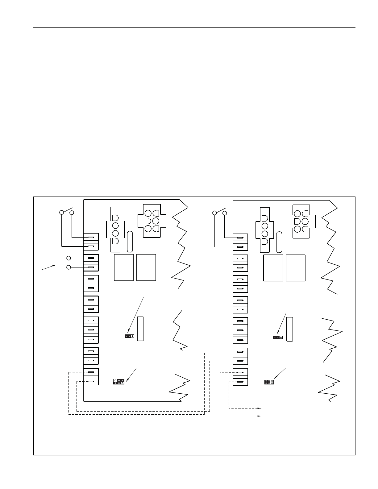
SECTION 10: WIRING
*OPTIONAL
SWITCH
SATELLITE HEATER CONTROL
FOR SATELITTE
CONTROLLERS, J9 JUMPER CAN BE
LEFT IN ORIGINAL POSITION
REGARDLESS OF CONTROL METHOD.
J10 JUMPER POSITION
SHOWS "SATELLITE" DESIGNATION.
MODULATION CONTROL WIRING
TO ADDITIONAL SATELLITE
HEATER CONTROL TERMINALS
T28 and T29.
ON/OFF SWITCH
REQUIRED
MODULATION CONTROL WIRING
TO SATELLITE HEATERS
CENTRAL HEATER CONTROL
REMOTE ANALOG
CONTROL
SIGNAL FROM SEPARATE
CONTROLLER
0-10Vdc OR 4-20mA
ANALOG INPUT CONTROL IS
USED TO SELECT ANALOG
SIGNAL TYPE 0-10Vdc OR 4-20mA
(4-20mA POSITION SHOWN).
J10 JUMPER POSITION
SHOWS "CENTRAL"
DESIGNATION AND
"ANALOG" CONTROL METHOD.
J10
J9
W
R
-+
-
+
-+
OUT
RATE
FIRING
IN
RATE
FIRING
EXT. POT
GND
WIPER
HIGH
GND
BAR
SLIDE
GND
THERMISTOR
INPUT
ANALOG
THERMOSTAT
T31
T29
T19
T18
T16
T14
T27
T25
T30
T28
T17
T15
T13
T26
T24
-
+
J10
J9
W
R
-+
-
+
-+
OUT
RATE
FIRING
IN
RATE
FIRING
EXT. POT
GND
WIPER
HIGH
GND
BAR
SLIDE
GND
THERMISTOR
INPUT
ANALOG
THERMOSTAT
T31
T29
T19
T18
T16
T14
T27
T25
T30
T28
T17
T15
T13
T26
T24
A B
A B
* Separate on/off switch is optional for "satellite" heaters (install at user level). On/Off switch is used to
disable heater operation or reset a heater that is in "lockout" mode. If on/off switch is not desired, leave
jumper wire between R and W terminals in place.
For 4-20mA control of the heater(s) firing rate, the
following control conditions apply:
ON/OFF relay at the external controller or BMS must
be wired to R and W terminals on the heater control
board to turn the heater ON and OFF.
(Open Circuit = OFF, Closed Circuit = ON).
Minimum rated input at 1% of signal (0-4 mA).
Full rated input at 90% of signal (18 mA).
Input varies linearly between 4 mA and 18 mA.
BMS controllers often offer PID loop control that can
optimize output signal and rate of change of the
output signal. Common analog application is defined
as follows:
1. BMS sensors that monitor zone air
temperatures are located in the heating space.
FIGURE 26: Analog Control Signal Wiring Diagram
2. Based on sensed temperatures, the BMS will
output an analog signal for the desired heater(s)
firing rate.
3. As heater(s) receive the analog signal from the
BMS, the heater(s) modulate to the corresponding firing rate.
4. As sensed air temperature rises closer to the
desired temperature setpoint, the BMS will
reduce the output signal, in turn reducing heater
firing rate.
5. Upon satisfying temperature setpoint, the BMS
will either:
a. Tu
rn off the heater.
b. Reduce the signal so that the minimum
heater firing rate is maintained until the
sensed temperature rises above the
setpoint to a cut-off limit temperature when
the BMS turns off the heater.
49 of 71
Page 56
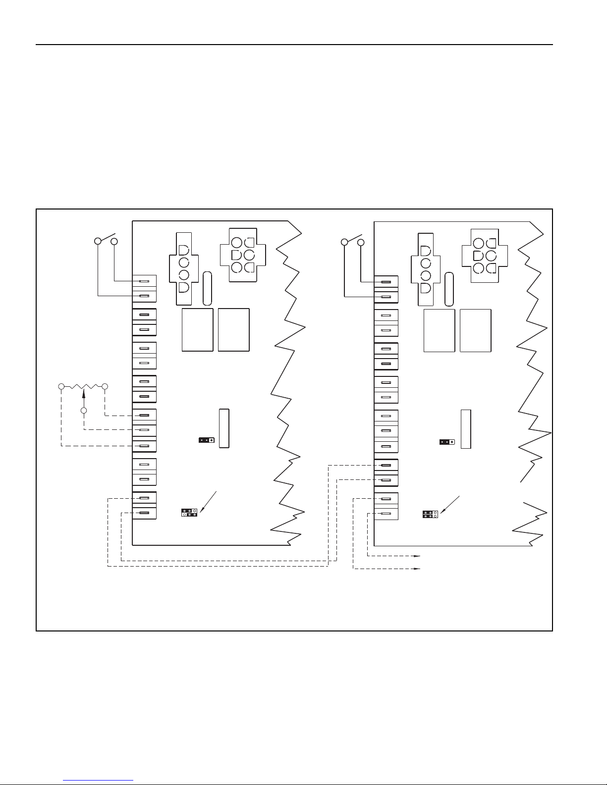
VM-SERIES INSTALLATION, OPERATION AND SERVICE MANUAL
*OPTIONAL
SWITCH
SATELLITE HEATER CONTROL
J10 JUMPER POSITION
SHOWS "SATE LLITE" DESIGNAT ION.
MODULATION CONTROL WIRING
TO ADDITIONAL SATE LLITE
HEATER CONTROL TERMINALS
T28 AND T29.
MODULATION CONTROL WIRING
TO SATE LLITE HEATERS
CENTRAL HEATER CONTROL
J10
W
R
-+
-
+
-+
OUT
RATE
FIRING
IN
RATE
FIRING
EXT. POT
GND
WIPER
HIGH
GND
BAR
SLIDE
GND
THERMISTOR
INPUT
ANALOG
THERMOSTAT
T31
T29
T19
T18
T16
T14
T27
T25
T30
T28
T17
T15
T13
T26
T24
J10
W
R
-+
-
+
-+
OUT
RATE
FIRING
IN
RATE
FIRING
EXT. POT
GND
WIPER
HIGH
GND
BAR
SLIDE
GND
THERMISTOR
INPUT
ANALOG
THERMOSTAT
T31
T29
T19
T18
T16
T14
T27
T25
T30
T28
T17
T15
T13
T26
T24
ON/OFF SWITCH
or THERMOSTAT
A B
A B
J10 JUMPER POSITION
SHOWS "CENTRAL"
DESIGNATION AND
"POTENTIOMETER"
CONTROL METHOD.
POTENTIOMETER
(10K Ohm)
* Separate on/off switch is optional for "satellite" heaters (install at user level).
On/Off switch is used to disable heater operation or reset a heater that is in "lockout" mode.
If on/off switch is not desired, leave jumper wire between R and W terminals in place.
10.5.9 Potentiometer Control Device
Potentiometer (10K Ohm"Linear Taper") device offers
manual control over heater(s) firing rate. This type of
potentiometer can be found at Radio Shack
®
.
Potentiometer dial position directly dictates heater(s)
firing rate. Dial positions range between "Min" and
"Max". Minimum and maximum heater firing rates
(inputs) are marked on the heater's rating plate. ON/
OFF switch or thermostat is used to disable heater
operation or reset heater from lockout.
FIGURE 27: Potentiometer Control Wiring Diagram
50 of 71
Page 57
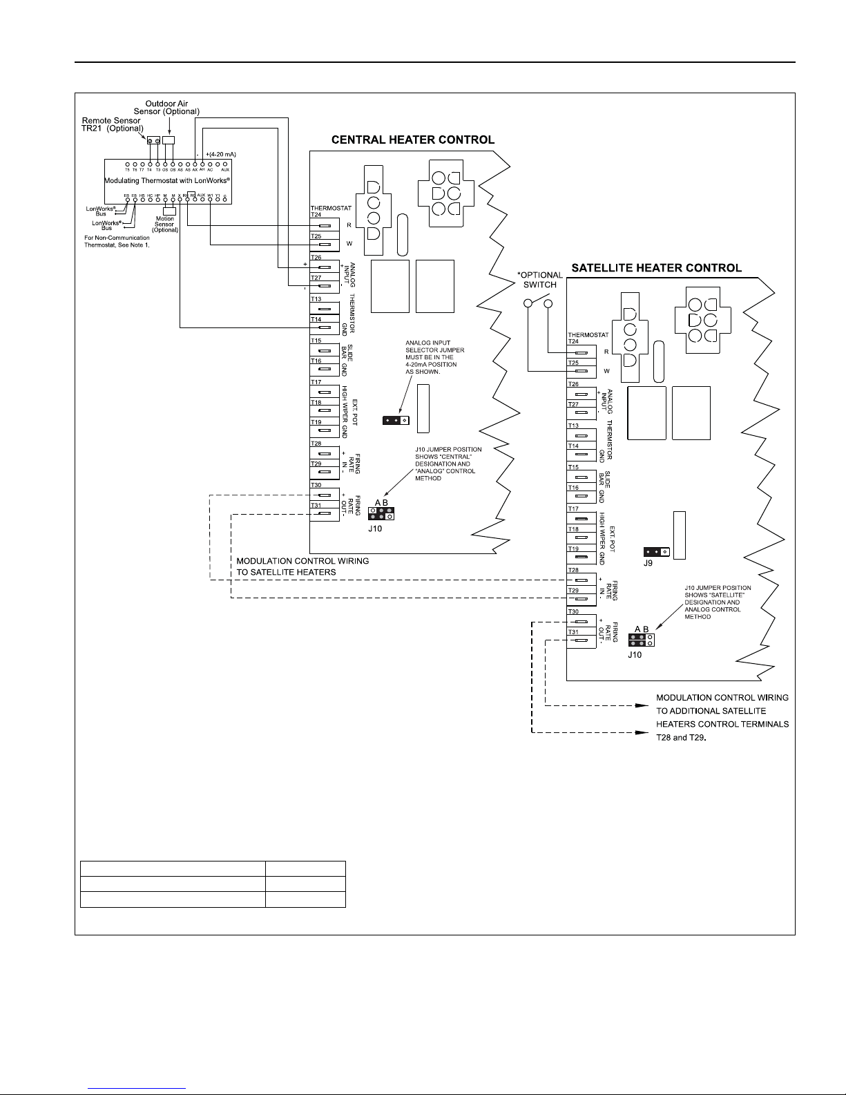
SECTION 10: WIRING
Description Part Number
Thermostat, modulating 90425105
Thermostat, modulating LonWorks
®
90425104
* Separate on/off switch is optional for "satellite" heaters (install at user level).
On/Off switch is used to disable heater operation or reset a heater that is in "lockout" mode.
If on/off switch is not desired, leave jumper wire between R and W terminals in place.
NOTE: 1. For non-communicating thermostats without LonWorks
®
bus, thermostat terminals marked "EB"
will be marked "_____" and no LonWorks
®
bus communication wires are used.
FIGURE 28: Modulating Thermostat Wiring Diagram (LonWorks
®
[4-20 mA] optional)
51 of 71
Page 58
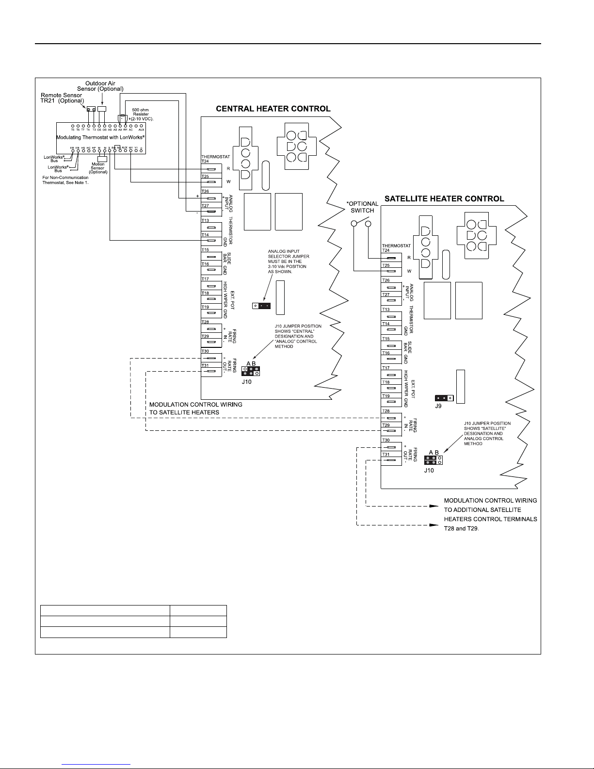
VM-SERIES INSTALLATION, OPERATION AND SERVICE MANUAL
* Separate on/off switch is optional for "satellite" heaters (install at user level).
On/Off switch is used to disable heater operation or reset a heater that is in "lockout" mode.
If on/off switch is not desired, leave jumper wire between R and W terminals in place.
NOTE: 1. For non-communicating thermostats without LonWorks
®
bus, thermostat terminals marked "EB"
will be marked "_____" and no LonWorks
®
bus communication wires are used.
Description Part Number
Thermostat, modulating 90425105
Thermostat, modulating LonWorks
®
90425104
FIGURE 29: Modulating Thermostat Wiring Diagram (LonWorks
optional)
®
[2-10Vdc with 500 Ohm resistor]
52 of 71
Page 59
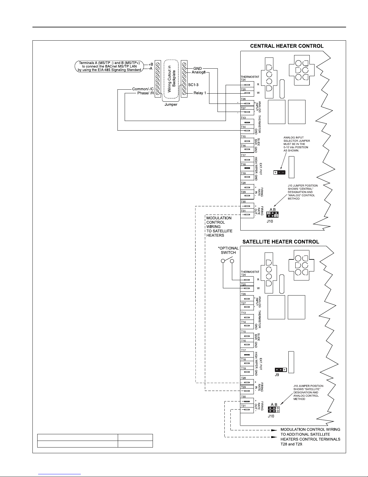
SECTION 10: WIRING
Description Part Number
Thermostat, modulating BACnet
®
90425109
NOTES:
1. A j umper is pre-installed between phase
R(24VAC) and SC1-3 (24VAC Relay).
2. Ground ONLY ONE END of the shielded cable.
* Separate on/off switch is optional for "satellite"
heaters (install at user level). On/Off switch is used
to disable heater operation or reset a heater that is
in "lockout" mode. If on/off switch is not desired,
leave jumper wire between R and W terminals in
place.
FIGURE 30: Modulating Thermostat Wiring Diagram with BACnet
®
(optional)
53 of 71
Page 60
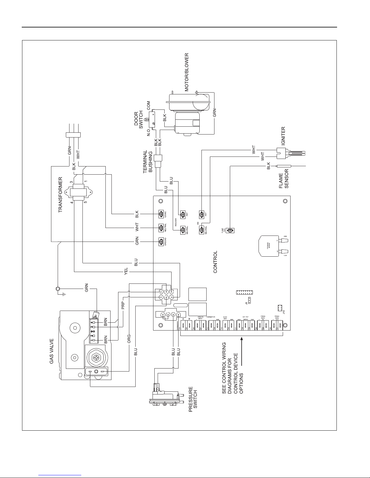
VM-SERIES INSTALLATION, OPERATION AND SERVICE MANUAL
10.6 Internal Wiring
See Page 41, Section 10.2 through Page 50, Section
10.5.9 for temperature control device options and
wiring schematic.
54 of 71
Page 61
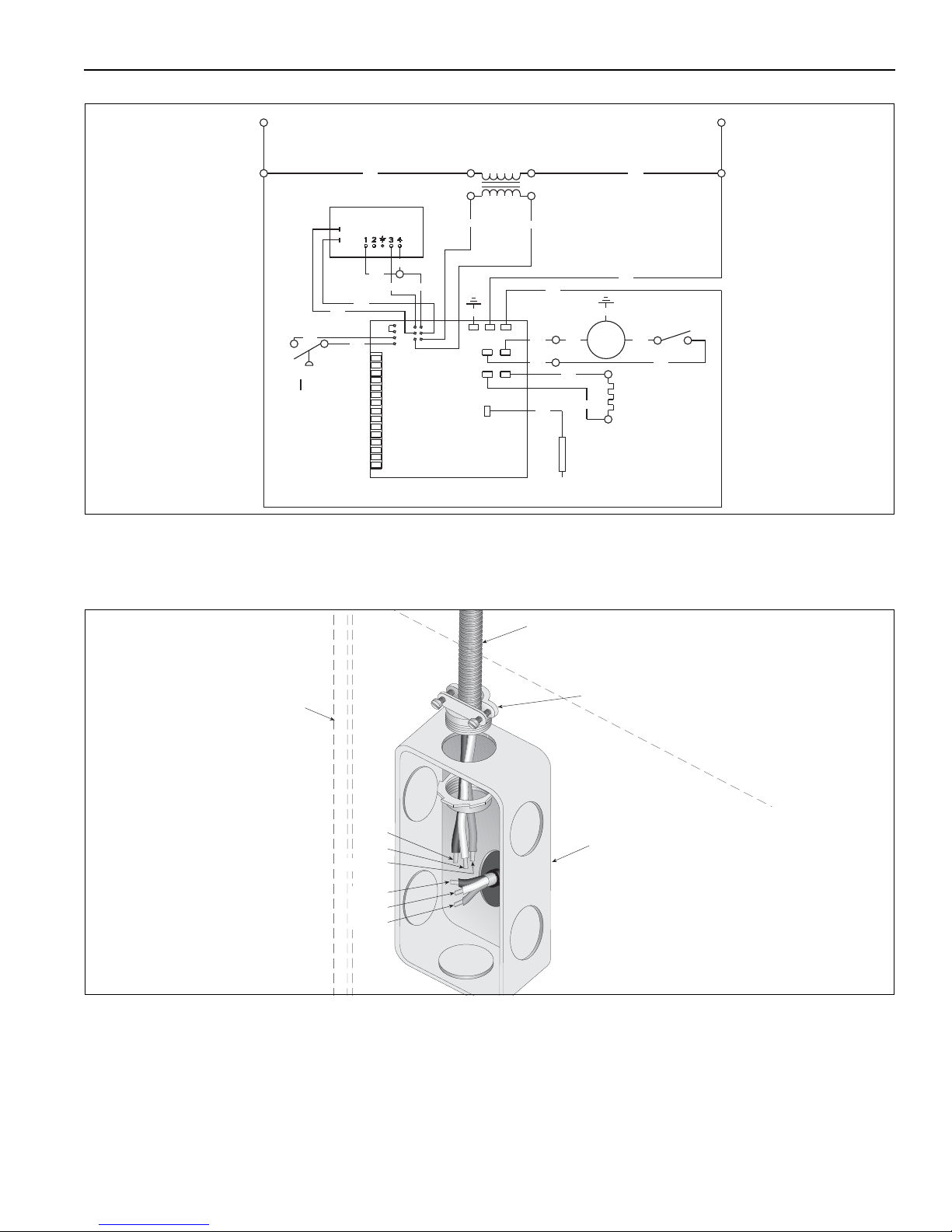
10.7 Ladder Diagram
L1
L2
24V
120V
CONTROL
GAS VALVE
SURFACE
IGNITER
HOT
MOTOR
FLAME
SENSOR
SWITCH
DOOR
AIR SWITCH
BLK
WHT
WHT
BLK
BLK
BLK
BLK
WHT
WHT
BLU
YEL
ORG
BLU
BLU
BLU
PRP
BRN
BRN
BRN
BLU
BLK
GRN
BLU
BLU
GRN
BX or Romex Connector
Junction Box
Electrical Cord or
Flexible Conduit
Burner
Connect wires together
with suitable approved
wire connectors.
Green to Ground
White to L2
Black to L1
L1
L2
Ground
Black
White
Green
SECTION 10: WIRING
See Page 41, Section 10.2 through Page 50, Section 10.5.9 for temperature control device options and
wiring schematic.
10.8 Electrical Connection to the Burner
55 of 71
Page 62
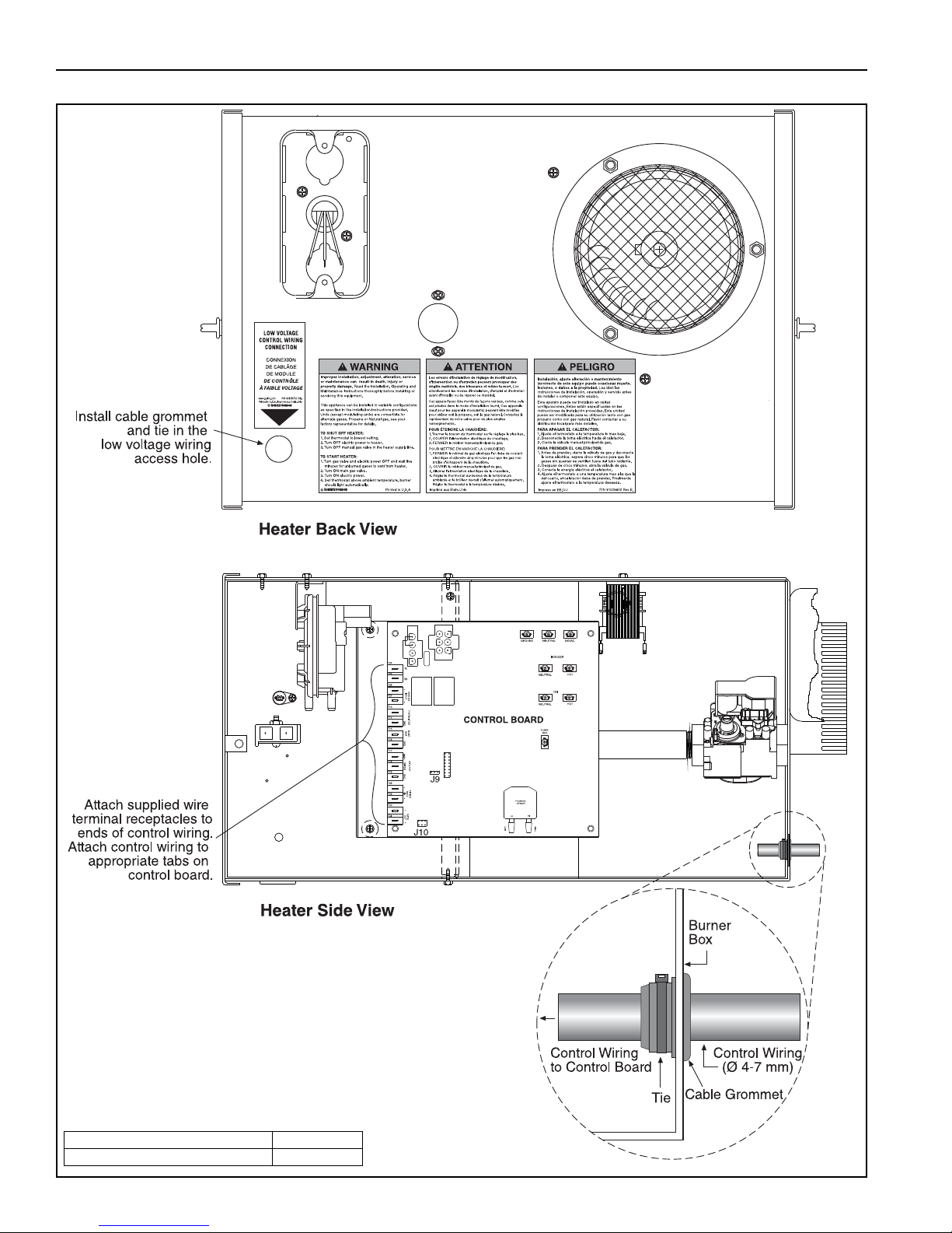
VM-SERIES INSTALLATION, OPERATION AND SERVICE MANUAL
Description Part Number
Cable Grommet with Tie 91309605
10.9 Low Voltage Control Wiring Installation
56 of 71
Page 63
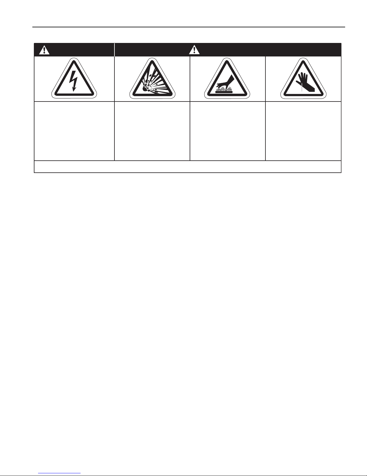
SECTION 11: OPERATION AND MAINTENANCE
SECTION 11: OPERATION AND MAINTENANCE
DANGER
Electrical Shock Hazard
Disconnect electric
before service.
Heater must be
connected to a properly
grounded electrical
source.
Failure to follow these instructions can result in death, electric shock, injury or property damage.
11.1 Sequence of Operation
The control inside the heater's control compartment
is equipped with a tri-color LED. The LED offers
comprehensive diagnostic capability. The LED
status will be referenced throughout this section.
1. When the control is powered and there is no call
for heat from external heat demand device, the
LED on the control flashes slow green; LED is
ON for the same period it is OFF.
2. On a call for heat from the heat demand device,
the heater will go to PRE-PURGE. The LED
indicates one green flash. The blower speed will
vary as the pressure switch setpoints are
verified. When the PRE-PURGE is successfully
completed, the heater will go into the
PRE-IGNITION state and power the hot surface
igniter (H.S.I.).
3. After the igniter warms up, the heater will go to
the IGNITION state. Power is supplied to the
gas valve operator, gas flows, ignites and the
flame is proven. The LED shows two green
flashes on the LED. If a flame is not sensed, the
heater will RETRY, See Item 6 below for further
details.
4. When the IGNITION state is completed, the
heater will go to WARM UP state. The unit will
fire at maximum input for 15 seconds. When the
WARM UP state is completed the device will go
into RUN state. The control board will monitor
the heat demand device and modulate the
heater input to meet the demand. The LED still
shows two green flashes.
5. When the call for heat has been satisfied, the
heater closes the gas valve. The blower
Explosion Hazard
Turn off gas supply to
heater before service.
WARNING
Burn Hazard
Allow heater to cool
before service.
Tubing may still be hot
after operation.
continues to run for a 45 second post-purge
period. After the post-purge, the heater turns
OFF and the LED on the control board flashes
slow green.
6. If flame is lost at any time during heater
operation, the heater will RETRY for ignition.
Upon RETRY the LED shows a fast yellow flash
(LED rapidly flashes). The heater will RETRY for
ignition three times. After four ignition attempts,
the heater will lockout for one hour or until reset.
To reset the heater, remove power for 10
seconds, then re-apply power. Turn heater ON
with call for heat from the heat demand device.
11.2 To Shut Off Heater
Set external heat demand dev
Turn OFF electric power to heater.
Turn OFF manual gas valve in the heater supply line.
11.3 To Start Heater
Turn gas valve and electric power OFF and wait five
minutes for unburned gases to vent from heater.
Turn ON main gas valve.
Turn ON electric power.
Set heat demand device to desired temperature.
Burner should light automatically.
11.4 Pre-Season Maintenance and Annual
Inspection
To e n s ure your safety and years of trouble-free
operation of the heating system, service and annual
inspections must be done by a contractor qualified in
the installation and service of gas-fired heating
equipment.
Turn off gas and electric supplies before performing
Cut/Pinch Hazard
Wear protective gear
during installation,
operation and service.
Edges are sharp.
ice to lowest setting.
57 of 71
Page 64
VM-SERIES INSTALLATION, OPERATION AND SERVICE MANUAL
service or maintenance. Allow heater to cool before
servicing.
Before every heating season, a contractor qualified in
the installation and service of gas-fired heating
equipment must perform a thorough safety
inspection of the heater.
For best performance, the gas, electrical, thermostat
connections, tubing, venting, suspensions and
overall heater condition should be thoroughly
inspected.
NOTE: Gas flow and burner ignition are among the
first things that should be inspected.
Please See Page 58 for suggested items to inspect.
Installation Code and Annual Inspections:
All installation and service of VAL-CO equipment
must be performed by a contractor qualified in the
installation and service of equipment sold and
supplied by Val-Co and conform to all requirements
set forth in the VAL-CO manuals and all applicable
governmental authorities pertaining to the
installation, service, operation and labeling of the
equipment.
To help facilitate optimum performance and safety,
Val-Co recommends that a qualified contractor
conduct, at a minimum, ann
ual inspections of your
VAL-CO eq uipment and perform service w here
necessary, using only replacement parts sold and
supplied by Val-Co.
The Vicinity of the Heater Do not store or use flammable objects, liquids or vapors near the heater.
Immediately remove these items if they are present.
See Page 6, Section 3.
Vehicles and Other
Objects
Maintain the clearances to combustibles.
Do not hang anything from, or place anything on, the heater.
Make sure nothing is lodged underneath the reflector, in between the tubes or
in the decorative or protective grilles (included with select models).
Immediately remove objects in violation of the clearances to combustibles.
See Page 6, Section 3.
Reflector Support reflector with reflector hanger and support strap.
Reflector must not touch tube.
Make sure there is no dirt, sagging, cracking or distortion.
Do not operate if there is sagging, cracking or distortion.
Make sure reflectors are correctly overlapped. See Page 20, Section 6.5.1.
Clean outside surface with a damp cloth.
Vent Pipe Venting must be intact. Using a flashlight, look for obstructions, cracks on the
pipe, gaps in the sealed areas or corrosion.
The area must be free of dirt and dust. Clean as required.
Remove any carbon deposits or scale using a wire brush.
See Page 31, Section 8.
Outside Air Inlet Inlet must be intact. Look for obstructions, cracks on the pipe, gaps in the
sealed areas or corrosion.
The area must be free of dirt and dust. Clean and reinstall as required.
Tubes Make sure there are no cracks.
Make sure tubes are connected and suspended securely.
See Page 12, Section 6.
Make sure there is no sagging, bending or distortion.
Clean or replace as required.
Gas Line Check for gas leaks. See Page 37, Section 9.
58 of 71
Page 65
SECTION 11: OPERATION AND MAINTENANCE
Burner Observation
Window
Blower Scroll, Wheel and
Motor
Make sure it is clean and free of cracks or holes.
Clean and replace as required.
Compressed air or a vacuum cleaner may be used to clean dust and dirt.
Burner Cup and Orifice Clear of obstructions (even spider webs will cause problems).
Carefully remove any dust and debris from the burner.
Hot-Surface Igniter Replace if cracked or broken.
Heat Demand Device:
Thermostat, Zone Sensor,
External Pot or 0-10 Vdc or
There should be no exposed wire or damage to the device or wiring.
See Page 39, Section 10.
4 - 20 mA wiring
Suspension Points Make sure the heater is hanging securely.
Look for signs of wear on the chain or ceiling.
See Page 13, Figure 11.
Decorative and Protective
Grille (optional)
The grille must be securely attached.
Check that the side reflector extensions are installed correctly and secured in
place if necessary. (Decorative grille only.)
See Page 28, Section 7.5 and Page 30, Section 7.6
Make sure shield is installed correctly and secured in place if necessary.
(Decorative grille only.) See Page 29, Section 7.5.2.
Lower Clearance Shield
(optional)
The lower shield must be securely attached.
Inspect shield support straps and lower clearance shield anchor points.
See Page 28, Section 7.4.
Make sure shield is installed correctly and secured in place if necessary.
See Page 28, Section 7.4.
Silicone Tubing Ensure tight, secure fit on all pressure fittings at gas valve, pressure switch,
pressure sensor, burner partition, and blower outlet.
Gas Valve Verify silicone tubing has a tight secure fit on "vent" fitting.
Verify that plastic cap on covering pressure regulator adjustment screw is
secure and has not been tampered with.
Do not remove plastic regulator cap or attempt to adjust valve pressure
regulator.
Verify all wiring connections.
Wall Tag If wall tag is present, make sure it is legible and acc
urate. Please contact Val-
Co or your VAL-CO independent distributor, if you need a wall tag. See Page
4, Section 2.1.
Safety Labels Product safety signs or labels should be replaced by the product user when
they are no longer legible. Please contact Val-Co or your VAL-CO independent distributor to obtain replacement signs or labels. See Page 2, Figure 1
through Page 3, Figure 2.
59 of 71
Page 66
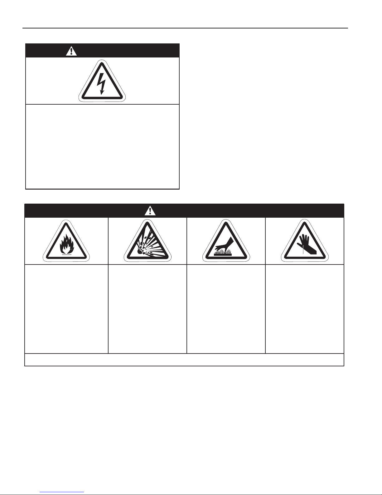
VM-SERIES INSTALLATION, OPERATION AND SERVICE MANUAL
Fire Hazard
Keep all flammable
objects, liquids and
vapors the minimum
required clearances to
combustibles away
from heater.
Some objects will catch
fire or explode when
placed close to heater.
Cut/Pinch Hazard
Wear protective gear
during installation,
operation and service.
Edges are sharp.
WARNING
Failure to follow these instructions can result in death, injury or property damage.
Burn Hazard
Allow heater to cool
before service.
Tubing may still be hot
after operation.
Explosion Hazard
Turn off gas supply to
heater before service.
SECTION 12: TROUBLESHOOTING
DANGER
Electrical Shock Hazard
Disconnect electric before service.
More than one disconnect switch may be
required to disconnect electric from heater.
Heater must be properly grounded to an
electrical source.
Failure to follow these instructions can
result in death or electrical shock.
60 of 71
Page 67

SECTION 12: TROUBLESHOOTING
12.1 Control LED
The control inside the heater's control compartment
is equipped with a tri-color LED. The LED offers
comprehensive diagnostic capability. The LED is
showing some form of status signal at all times when
the control is powered. The color of the LED
differentiates normal from error conditions as follows:
GREEN indicates normal operation.
RED indicates an error condition.
YELLOW (fast flashing) indicates a RETRY attempt.
LED NOT LIT indicates no power to control.
12.2 General LED Codes
No LED: No Power to control.
Slow Green: LED slowly flashes on and off,
indicates power to the control
board but no call for heat.
GREEN, 1 flash: Call for heat indicates the
heater is performing the safe
start pre-purge function or
H.S.I. warm-up.
GREEN, 2 flashes: Call for heat indicates the
heater is performing light off,
heater warm-up, or heater run.
GREEN, 3 flashes: *Only applicable for
thermostat control*
Gas ON - No call for heat, unit
modulating from single stage
thermostat.
AMBER, 1 flash: Call for heat when flame signal
is below 1µA
AMBER,
Fast Flashing: Heater is in RETRY mode.
RED Steady LED: Control FAILURE,
No 24 V power supply.
RED, 1 flash: Lockout- Insufficient sensed
air pressure when blower is
on.
Condition could be caused by:
• Air Side Door
• Blower
• Obstruction in
inlet or outlet
• Pressure hose fittings
• Pressure Switch
RED, 2 flashes: Lockout- Blower air pressure
reads above zero level when
blower is off.
Condition is caused by
a pressure sensor failure or
complete blockage of air
intake or exhaust vent.
RED, 3 flashes: Lockout- Flame is sensed on
when it should be off or off
when it should be on.
Could be caused by:
• Flame Rod
• H.S.I.
• Gas Supply
• 120 V Supply Polarity
• Board Fault
RED, 4 flashes: Locko
ut- Gas Valve.
Condition caused by main
valve on gas valve.
Check gas valve wiring.
AMBER, 2 flashes: Gas ON - Call for heat when
flame signal is below 1µA
AMBER, 3 flashes: *Only applicable for
thermostat control*
Gas ON - No call for heat, unit
modulating from single stage
thermostat when flame signal
is below 1µA.
RED, 5 flashes: Lockout- Board Failure.
Board must be replaced.
RED, 6 flashes: Not used.
RED, 7 flashes: Lockout- Fuse Open.
Condition could be caused by:
• Fuse blown
• High Limit Switch open a
board location J3
61 of 71
Page 68

VM-SERIES INSTALLATION, OPERATION AND SERVICE MANUAL
RED, 8 flashes: Lockout- Pressure switch
failed to operate or modulation
current was incorrect.
Condition could be caused by:
• Pressure Sensor
• Pressure Switch
(faulty or hoses reversed)
• Gas Valve Modulation Coil
• Wire Harness (6 wire)
RED, 9 flashes: Lockout- Air Supply.
Condition could be caused by:
• Blower
• Pneumatic Conections to
Pressure Sensor
• Blockage in flue or inlet
62 of 71
Page 69
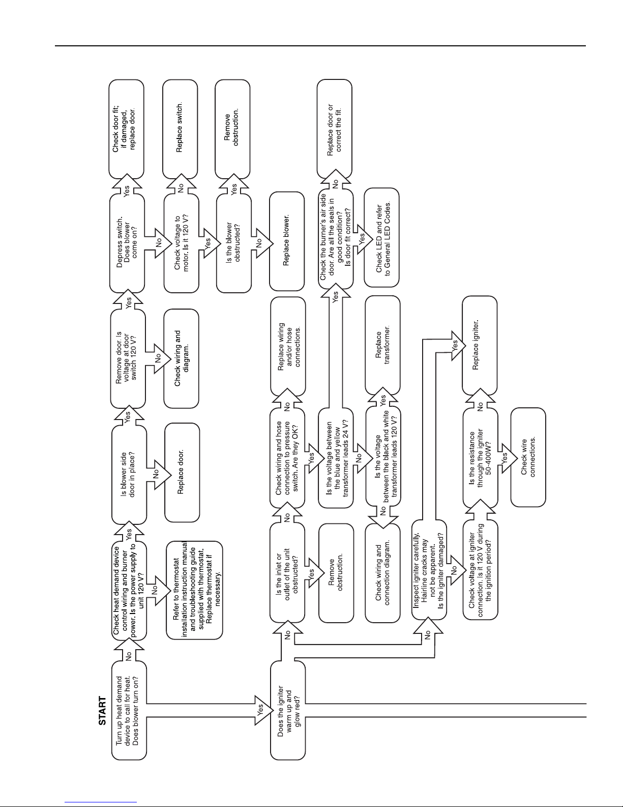
12.3 Troubleshooting Flow Chart
SECTION 12: TROUBLESHOOTING
63 of 71
Page 70
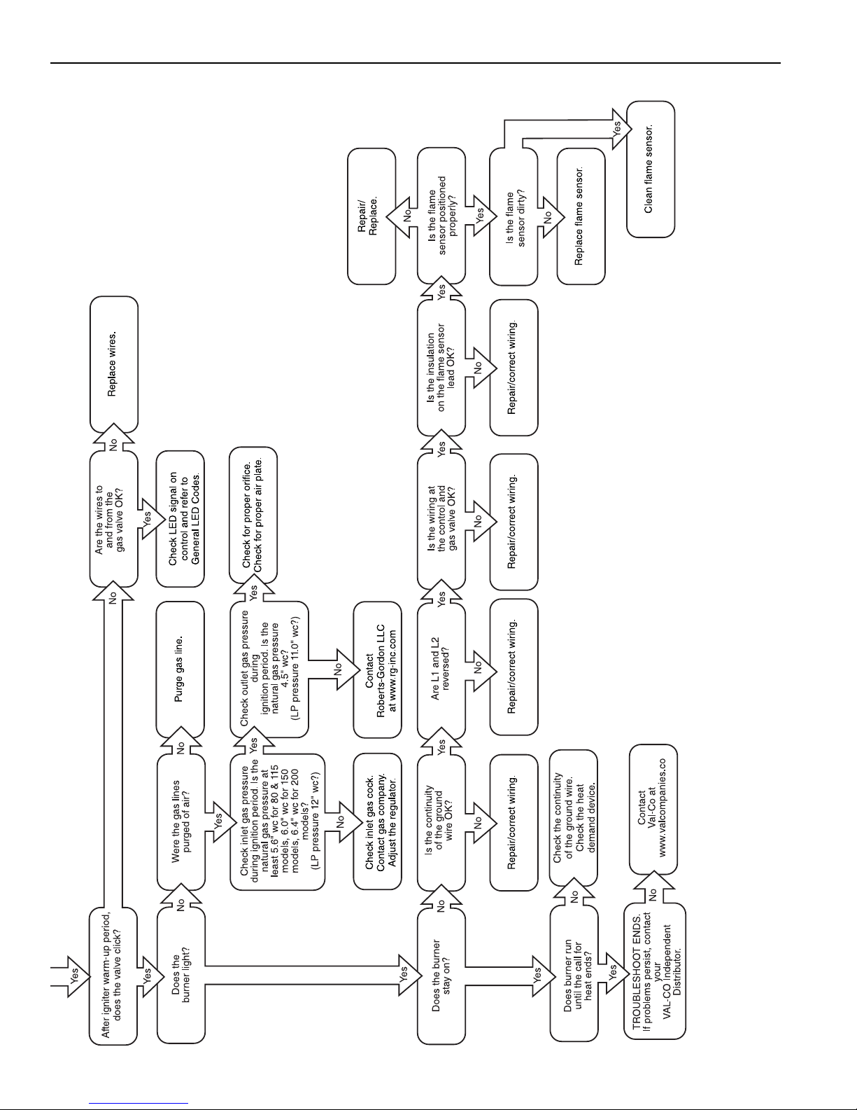
VM-SERIES INSTALLATION, OPERATION AND SERVICE MANUAL
64 of 71
Page 71
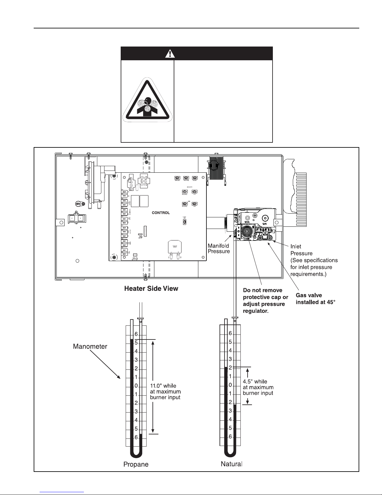
12.4 Manifold Gas Pressure Measurement
WARNING
Carbon Monoxide Hazard
Do not adjust gas valve
pressure regulator.
Do not tamper with sealed parts.
Pressure regulator is factory
calibrated for safe operation.
Failure to follow these
instructions can result in death
or injury.
SECTION 12: TROUBLESHOOTING
65 of 71
Page 72
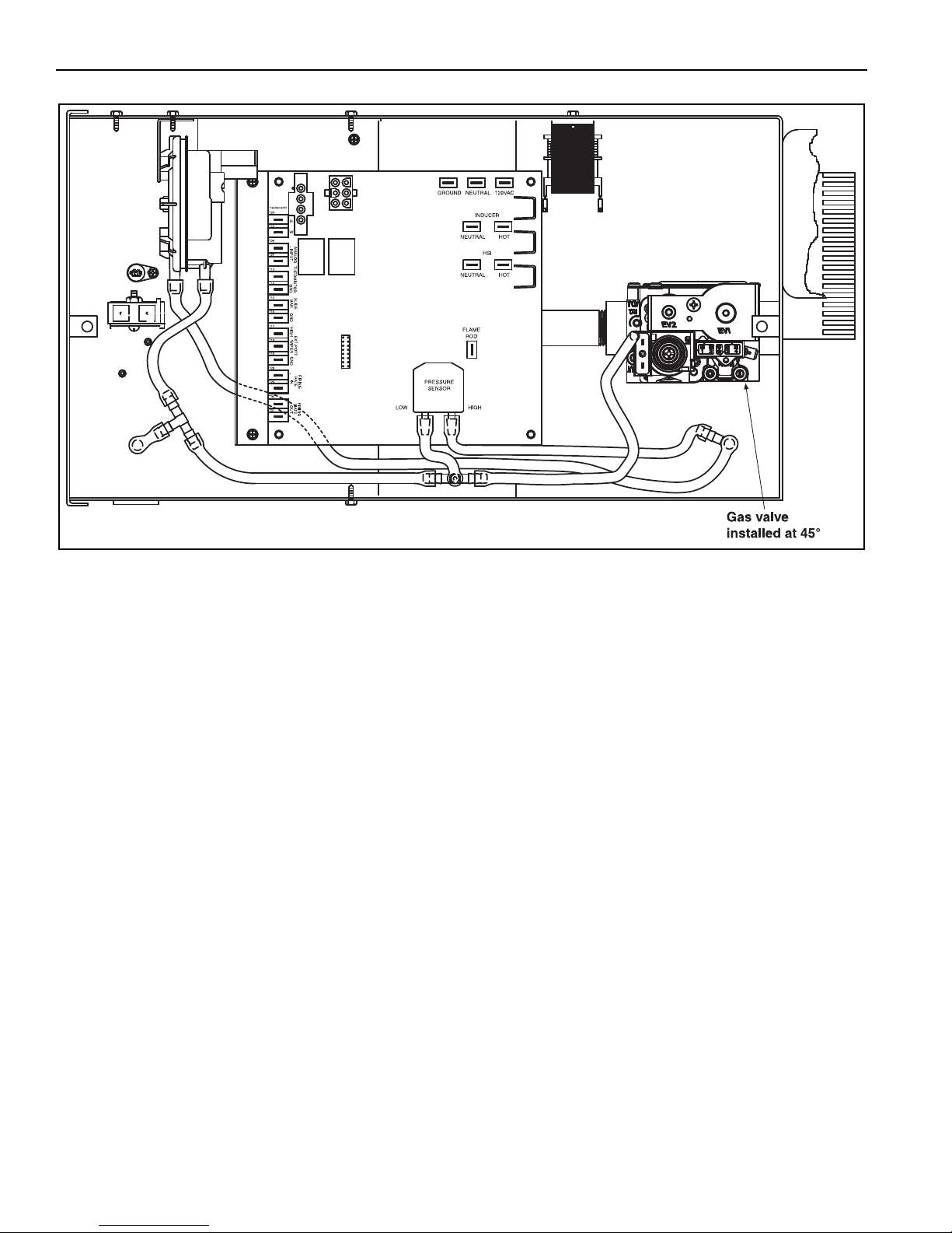
VM-SERIES INSTALLATION, OPERATION AND SERVICE MANUAL
12.5 Pneumatic Connections
66 of 71
Page 73
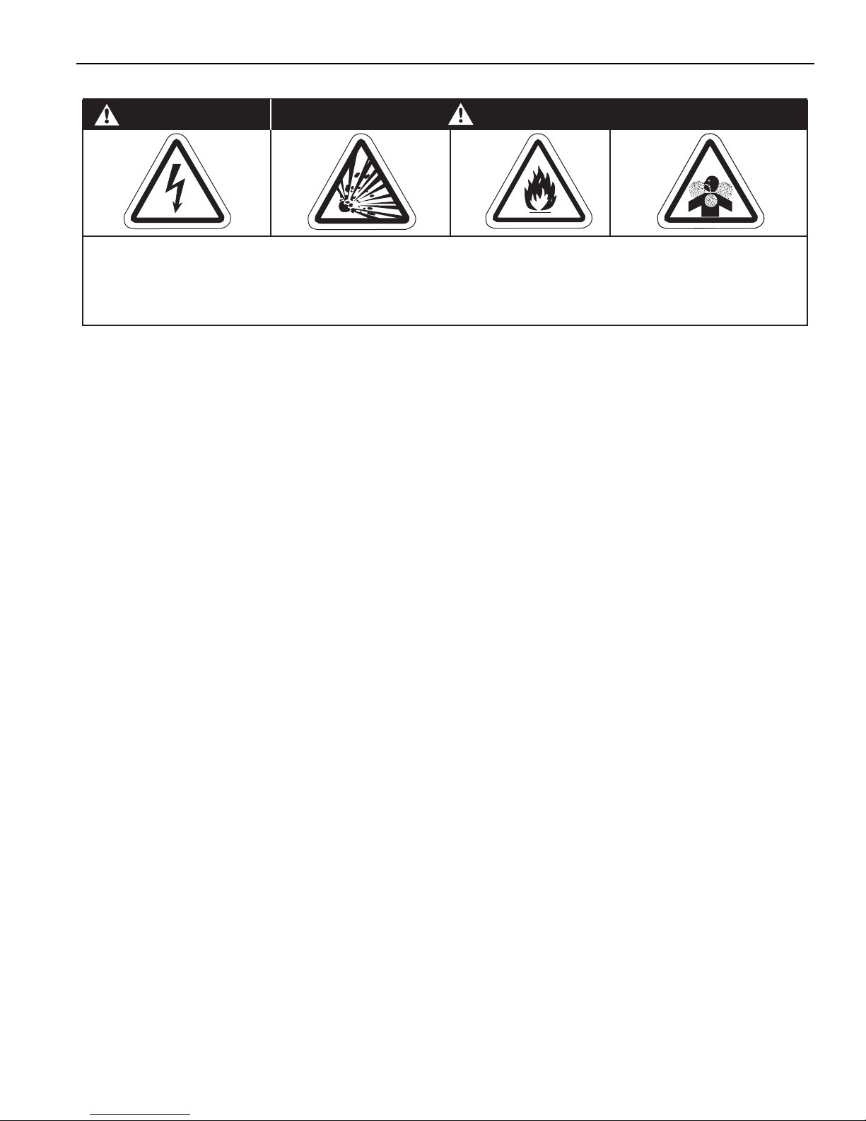
SECTION 13: REPLACEMENT PARTS
Carbon Monoxide Hazard
WARNING
Use only genuine VAL-CO replacement parts per this installation, operation and service manual.
Failure to follow these instructions can result in death, electric shock, injury or property damage.
Explosion Hazard
DANGER
Electrical Shock Hazard
Fire Hazard
SECTION 13: REPLACEMENT PARTS
67 of 71
Page 74
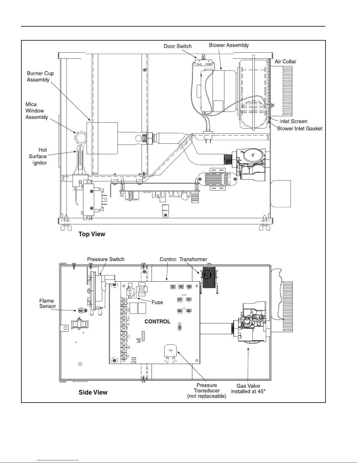
VM-SERIES INSTALLATION, OPERATION AND SERVICE MANUAL
68 of 71
Page 75
SECTION 13: REPLACEMENT PARTS
Description Part Number
Gas Valve (Natural) 90033105K
Gas Valve (LP) 90033104K
Tube Gasket 02568200
Blower Inlet Gasket (80, 115 models) 03050900
Blower Inlet Gasket (150, 200 models) 90709910
Blower Assembly (80, 115) 90708602-P
Blower Assembly (150, 200) 90709900-P
Air Collar (80, 115 models) 91911700
Air Collar (150, 200 models) 91911701
Inlet Screen (80, 115) 03050800
Inlet Screen (150, 200) 09050001
Door Switch 90436800
Burner Cup Assembly 03020100
Hot Surface Igniter 90436600K
Mica Window Assembly 02553203
Flame Sensor 90439300
Transformer 90436900K
Fuse (Control) 3 A 91321403
Pressure Switch
(80 NG, 80 LP, 115 NG, 115 LP) 90439812K
(150 NG, 150 LP, 200 NG, 200 LP) 90439803K
Control
80NG 90320109K
80LP 90320110K
115NG 90320111K
115LP 90320112K
150NG 90320113K
150LP 90320114K
200NG 90320115K
200LP 90320116K
69 of 71
Page 76
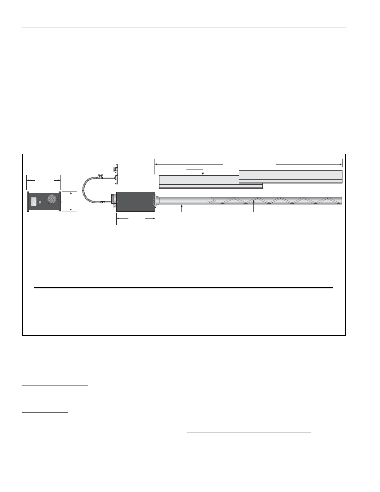
VM-SERIES INSTALLATION, OPERATION AND SERVICE MANUAL
Turbulator
(Select Models)
Side View
Reflector
17.5"
(44 cm)
Minimum Length "A"
End View
13.5"
(34 cm)
9.5"
(24 cm)
Burner Tube
Heat Input Rate
(NG)
Heat Input
Rate
(LP)
Length “A”
Recommended
Minimum Mounting Height*
Model
(Btu/h) X (1000)
Min. to Max.
(Btu/h) X
(1000)
Min. to Max.
Minimum Space Spot
VM-80 52 to 80 55 to 80 20' (6m) 12'-15' (3.6 - 4.5 m) 11' (3.3 m)
VM-115 75 to 115 78 to 115 30' (9m) 15'-20' (4.5 - 6 m) 15' (4.6 m)
VM-150 100 to 150 105 to 150 40' (12m) 20'-25' (6 - 7.6 m) 20’ (6.1 m)
VM-200 130 to 200 135 to 190 50' (15m) 25' (7.6 m) 23' (7 m)
SECTION 14: GENERAL SPECIFICATIONS
14.1 Material Specifications
14.1.1 Reflectors
.024 Aluminum
(Optional .024 Stainless Steel Type 304)
14.2 Heater Specifications
14.2.1 Control System
Modulating Gas Valve and Hot Surface Electronic
Ignition Control with Four-try, 100% shut-off,
Prepurge, Post-Purge, Auto Reset, Tri-color LED
Status/Fault Indicator.
General Specifications for the heaters are as follows:
14.3 Suspension Specifications
Hang heater with materials with a minimum working
load of 75 lbs (33 kg). See Page 13, Figure 11.
14.4 Controls Specifications
Time switches, sensors, etc. can be wired into the
electrical supply. External controls supplied as an
optional extra.
*See Page 6, Section 3 for clearances to combustibles.
GAS PRESSURE AT MANIFOLD:
Natural Gas: 4.5" wc
LP Gas: 11.0" wc
PIPE CONNECTION:
1/2" NPT (for 80 & 115 models)
3/4" NPT (for 150 & 200 models)
DIMENSIONS:
Vent Connection Size: 4" (10 cm)
Outside Air Connection Size:
5" (13 cm) for 150 & 200 models
4" (10 cm) for 80 & 115 models
Refer to figure above for dimensional information.
70 of 71
GAS INLET PRESSURE:
Natural Gas:
for 80, 115 & 150 models 5.5" wc Minimum
for 200 6.0" wc Minimum
LP Gas: 12.0" wc Minimum
ELECTRICAL RATING (ALL MODELS):
120V - 60 Hz., 4.8 A (start), 1.3 A (run)
14.0" wcMaximum
14.0" wcMaximum
14.0" wcMaximum
Page 77

SECTION 14: GENERAL SPECIFICATIONS
71 of 71
Page 78

Page 79

Page 80
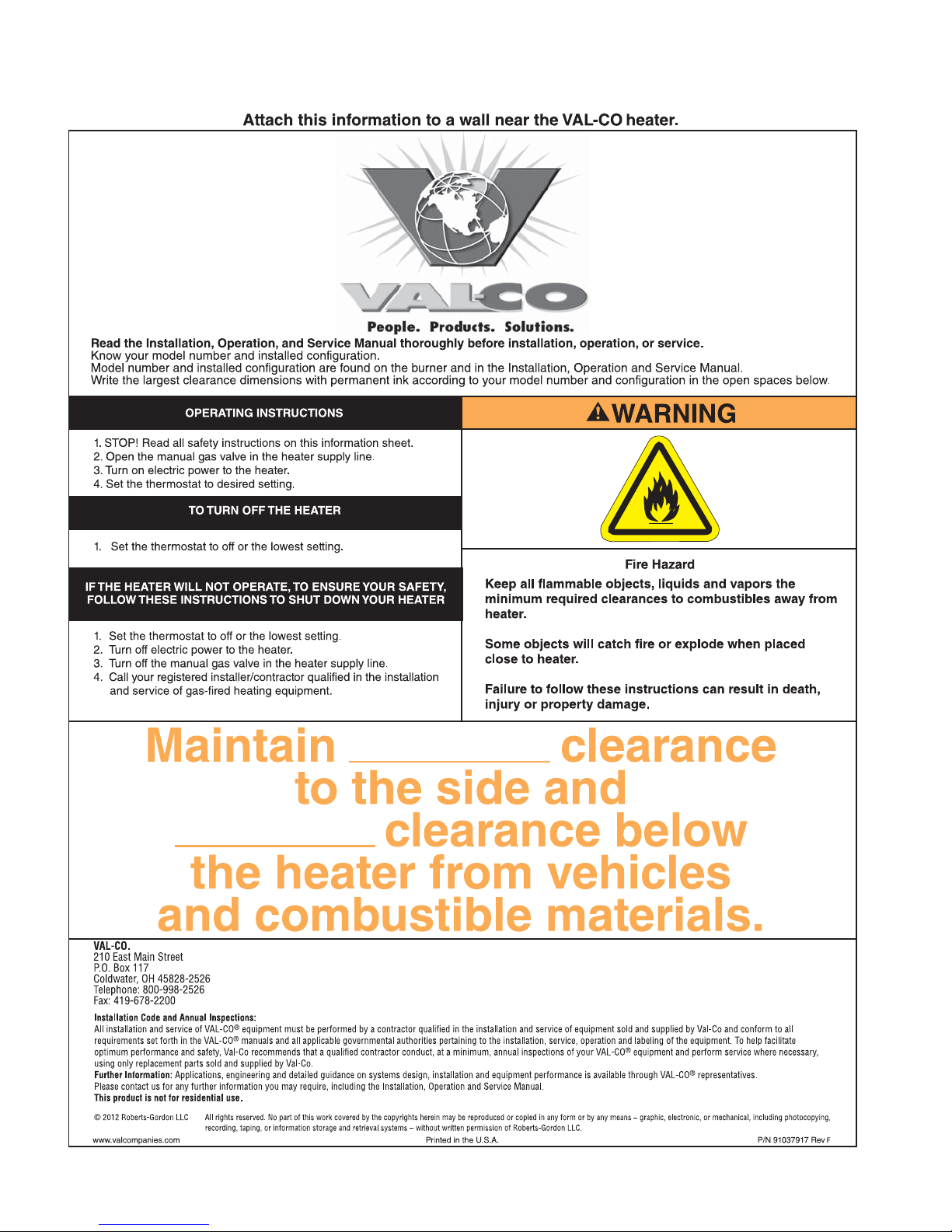
 Loading...