

Page 1
Express 50 Litres
Installation, operation and maintenance manual
Page 2

2
Contents
1. Introduction ...................................................................................................................................... 3
1.1 General .......................................................................................................................................... 3
1.2 Symbols used ................................................................................................................................ 3
1.3 Liabilities ........................................................................................................................................ 3
2. Safety ................................................................................................................................................. 4
2.1 General safety warnings ................................................................................................................ 4
2.2 Recommendations ........................................................................................................................ 4
2.3 Specic safety instructions ............................................................................................................ 4
3. Technical specications .................................................................................................................. 5
3.1 Technical data ............................................................................................................................... 5
3.2 Dimensions and connections ........................................................................................................ 6
3.3 Electrical diagram(s) ...................................................................................................................... 7
4. Description of the product .............................................................................................................. 8
4.1 General description ....................................................................................................................... 8
4.2 Operation principle ........................................................................................................................ 8
4.3 Main components .......................................................................................................................... 8
4.4 Standard delivery .......................................................................................................................... 8
5. Before installation ............................................................................................................................ 9
5.1 Installation regulations ................................................................................................................... 9
5.2 Installation requirements ............................................................................................................... 9
5.3 Choice of location .......................................................................................................................... 9
5.4 Transport ....................................................................................................................................... 9
6. Installation ........................................................................................................................................ 10
6.1 General .......................................................................................................................................... 10
6.2 Water connections ......................................................................................................................... 11
6.3 Electrical connections .................................................................................................................... 13
7. Commissioning ................................................................................................................................ 13
7.1 General .......................................................................................................................................... 13
7.2 Checklist before commissioning .................................................................................................... 13
7.3 Commissioning procedure ............................................................................................................. 13
8. Operation .......................................................................................................................................... 14
8.1 General .......................................................................................................................................... 14
9. Maintenance ...................................................................................................................................... 15
9.1 Standard inspection & maintenance operations ............................................................................ 15
10. Troubleshooting ............................................................................................................................. 16
10.1 Fault nding ................................................................................................................................. 16
11. Warranty .......................................................................................................................................... 17
11.1 General ........................................................................................................................................ 17
11.2 Warranty conditions ..................................................................................................................... 17
11.3 Water supply requirements .......................................................................................................... 17
11.4 Claims under warranty ................................................................................................................. 17
11.5 Exclusions ................................................................................................................................... 17
12. Decommissioning .......................................................................................................................... 18
12.1 Decommissioning procedure ....................................................................................................... 18
13. Spare parts ...................................................................................................................................... 20
13.1 Spare parts list ............................................................................................................................ 21
Page 3

3
1. Introduction
1.1 General
The following instructions are offered as a guide to
the user and installer. The installation must be carried
out by a competent plumbing and electrical installer in
accordance with:
� Building Regulations Part G and L
� The Building Standards (Scotland) Regulations
� The Building Regulations (Northern Ireland)
� I.E.E Wiring Regulations
� UK Water Regulations
1.2 Symbols used
In these instructions, various risk levels are employed
to draw the user’s attention to particular information. In
doing so we wish to safeguard the user, avoid hazards
and guarantee the correct operation of the appliance.
DANGER
Risk of a dangerous situation causing serious
physical injury.
WARNING
Risk of dangerous situation causing slight
physical injury.
CAUTION
Risk of material damage.
Signals important information.
1.3 Liabilities
Manufacturers liability
Our products are manufactured in compliance with
the requirements of the various applicable European
Directives.
This appliance complies with the requirements of the
CE marking directive and is Kiwa approved to show
compliance with Building Regulations (Part G, section
G3).
In the interest of UK customers, we are continuously
endeavouring to make improvements in product
quality. All the specications stated in this document
are therefore subject to change without notice.
Our liability as the manufacturer may not be invoked in
the following cases:
� Failure to abide by the instructions for using the
appliance.
� Faulty or insufcient maintenance of the appliance.
� Failure to abide by the instructions for installing the
product.
Installer's liability
The installer is responsible for the installation and the
commissioning of the appliance. The installer must
respect the following instructions:
� Read and follow the instructions given in the
manual provided with the appliance.
� Carry out installation in compliance with the
prevailing legislation and standards.
� Perform the initial start up and carry out any checks
necessary.
� Explain the installation to the user.
� If maintenance is necessary, warn the user of the
obligation to check the appliance and maintain it in
good working order.
� Give the instruction manual to the user.
� Complete the warranty registration card.
Users liability
To guarantee optimum operation of the appliance, the
user must respect the following instructions:
� Read and follow the instructions given in the
manual provided with the appliance.
� Call on qualied professionals to carry out
installation and initial start up.
� Ask your installer to explain your installation to you.
� Have your required checks and services done.
� Keep the instruction manuals in good condition and
available for future reference.
T
his appliance can be used by children
aged from 8 years and above and
persons with reduced physical sensory or
mental capabilities or lack of experience
and knowledge if they have been given
supervison or instruction concerning use of
the appliance in a safe way and understand
the hazards involved. Children shall not
play with the appliance. Cleaning and user
maintenance shall not be made by children
without supervision.
Children must be supervised to ensure they
do not play with the appliance.
Page 4

4
2. Safety
Do not connect any pressure-relief device
to the vent pipe of this water heater.
How hot water can be drained. (see page 11
for more details).
If the supply cord is damaged, it must
be replaced by the manufacturer, its service
agent or simularly qualied persons in order
to avoid a hazard.
2.1 General safety warnings
2.2 Recommendations
2.3 Specic safety instructions
WARNING
� Install only as a CISTERN FED
appliance, failure to do so will invalidate
any guarantee and may lead to a
dangerous installation.
CISTERN FED INSTALLATION
� When installed as a Cistern Fed water
heater the cold water supply must be
from a feed cistern complying with
Water Regulations Schedule 2, section
7, paragraph 16.
� A vent pipe must be connected to the
vented top of the heater. The vent pipe
must rise continuously and be arranged
to discharge into the cold water feed
cistern.
� The vent pipe must have a minimum
bore of 19mm.
� More than one conventional tap can be
supplied.
WARNING
� Only competent persons having
received adequate training are
permitted to work on the appliance and
the installation.
� Do not tamper with any of the safety
valves or controls supplied with the
appliance.
� Before any work, switch off the mains
supply to the appliance.
CAUTION
Do not operate the immersion heater until the
appliance has been lled with water.
WARNING
When handling the appliance, take appropriate
precautions for the weight of the appliance.
Weights can be found in section 3, p5.
CAUTION
Annual maintenance is recommended to be
carried out by a competent person, see section
9, page 15.
WARNING
� This appliance is supplied with a
factory temperature setting of 54°C for
optimum energy efciency. However, in
some applications to aid in the control of
legionella it may be necessary to reset
this to a higher temperature. It is the
responsibility of the installer and end
user to ensure that where applicable the
requirements of the "Approved Code of
Practice L8: The control of legionella
bacteria in water systems" are met.
Page 5

5
3. Technical specications
3.1 Technical data
Product Name
Express
50L V 3kW
Product Code 7037070
Electrical rating 3.0kW @ 240V ~ / 2.8kW @
230V ~
Weight Empty kg 21
Weight Full kg 71
Capacity (Litres) 50
Heat up time (min) 65
Maximum Design (Rated) pressure (Max. head pressure Cistern Fed) 0.2MPa (2 bar) (20 metres)
Maximum design pressure for mains fed installation 1.MPa (10 bar)
Minimum supply pressure 0.04 MPa (0.4 bar)
Insulation thickness (min)
22mm
Product Name
Express
50L V 3kW
Suppliers name or trade mark Express
Supplier’s model identier
50L V 3kW
Storage volume V in litres 50
Mixed water at 40 °C V40 in litres 83
The declared load prole M
The water heating energy efciency class of the
model
C
The water heating energy efciency in % 38.4
The annual electricity consumption in kWh 1338
Daily fuel consumption Q
elec
in kWh 6.17
The thermostat temperature setting of the water
heater, as placed on the market by the supplier
54°C
Specic pecautions that shall be taken when
the water heater is assembled, installed or
maintained and disposed of at end of life.
See pages 3 to 21
Technical parameters in accordance with European Commission regulations 814/2013 and 812/2013
Table 1: Technical data
Table 2: Technical che
Page 6
6
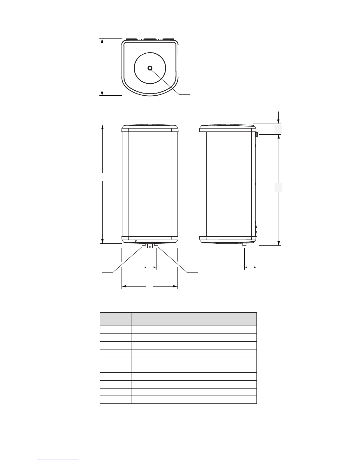
3.2 Dimensions and connections
Item 50L V 3kW
B 369mm
D 903mm
E 100mm
F 371mm
G 95mm
H OUTLET 22mm / 3/4"BSP (M)
I INLET 22mm / 3/4"BSP (M)
K
865mm
L
131mm
M
1/2" BSP female
B
D
E
F
G
H
I
K
L
M
Figure 1: General dimensions
Table 3: General dimensions table
Page 7

7
Figure 2: Wiring Diagram
SCHEMATIC DIAGRAM
RED WIRE B
TEMP
SAFETY
BLACK WIRE A
TERMINAL BLOCK
ELEMENT EARTH
(IMMERSION STUD)
L
N
E
OUTER CLADDING
L
N
THERMOSTAT ADJUSTMENT SPINDLE
FACTORY SET AT 54°C
2 1
B
A
RESET
CUT OUT
TO ELEMENT
CUT-OUT SENSOR
THERMOSTAT SENSOR
NEON
GREEN &
YELLOW
BLUE/BLACK
BROWN/RED
3.3 Electrical diagram(s)
Page 8
8
4. Description of the product
4.1 General description
This appliance is a purpose designed vented water
heater. The water heater has a stainless steel inner
vessel, which ensures an excellent standard of corrosion
resistance. The outer casing is a combination of resilient
thermoplastic mouldings and coated corrosion proofed
steel sheet. All products are insulated with CFC free
polyurethane foam to give good heat loss protection.
4.2 Operation principle
The appliance is used to heat and store hot water for
use in domestic & commercial applications.
The water is heated directly using a factory tted
electric heating element and thermostatically controlled
by an adjustable thermostat.
This appliance is vented which means that the tank
where the water is heated is vented to atmosphere and
no pressure is built up in the appliance. The appliance
can be installed in only one way, cistern fed.
A cistern fed appliance is fed from a cistern tank and
vents back into this tank through a pipe at the top of the
appliance. Multiple vented tap outlets can be used with
this installation.
4.3 Main components
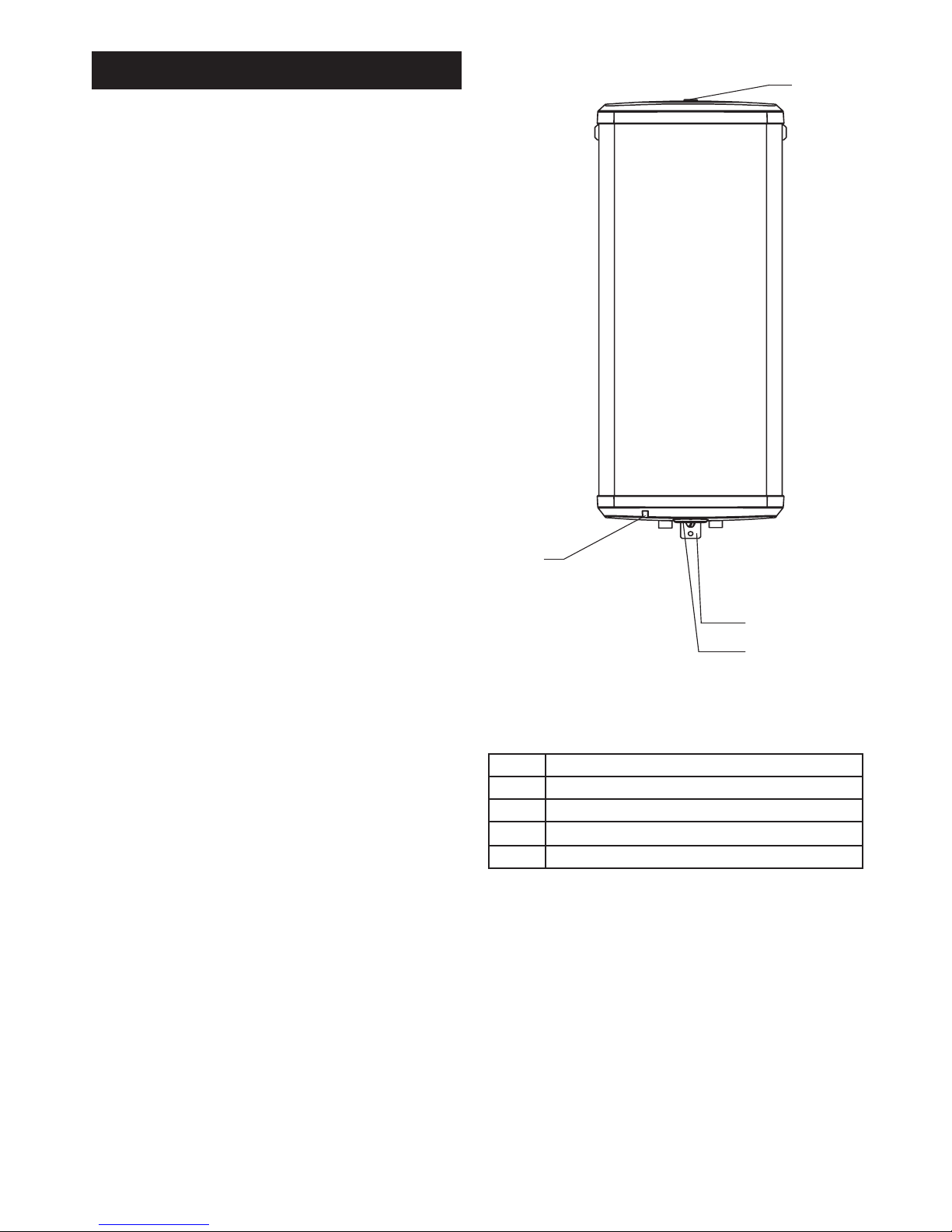
See gure 3: Main components
4.4 Standard delivery
The delivery includes:
� Water heater
� Wall mounting brackets
� Literature pack
� Instructions
� Warranty card
Please check all components are supplied in the
pack and advise your supplier if any are missing.
Figure 3: Main components
Item Description
1 Vent pipe connection for cistern fed installation
2 Wall Mounting Bracket (Lower)
3 Temperature control
4 Neon indicator
Table 4: Main components table
1
2
4
3
Page 9

9
5. Before installation
5.1 Installation regulations
5.2 Installation requirements
Water supply
It is recommended that the maximum water demand is
assessed and the water supply checked to ensure this
demand can be satisfactorily met.
� We suggest the minimum supply requirements
should be 0.04MPa (0.4 bar) pressure.
� A 15mm cold water supply is recommended.
� The higher the available pressure and ow rate the
better the system performance.
� The appliance has a maximum operating pressure
of 0.2Mpa (2 bar, 20 meteres head).
Limitations
The appliance should not be used in association with
any of the following:
� Situations where maintenance is likely to be
neglected.
� Water supplies that have either inadequate
pressure or where the supply may be intermittent.
� In areas where the water consistently contains a
high proportion of solids.
� In areas where the water supply contains chloride
levels that exceed 250mg/l.
5.3 Choice of location
The appliance must be vertically wall mounted.
Although location is not critical, the following points
should be considered:
� The appliance should be sited to ensure minimum
dead leg distances, particularly to the point of most
frequent use.
� Avoid siting where extreme cold temperatures will
be experienced. All exposed pipe work should be
insulated.
� Access to associated controls and immersion
heaters must be available for the servicing and
maintenance of the system.
� Clearance under the water heater should be at
least 300 mm to allow removal of the cover and
immersion heater.
� Ensure that the wall the appliance is to be mounted
on is capable of permanently supporting the weight
when full of water (see table 1, page 5 for weights).
5.4 Transport
Prior to installation the appliance should be transported
and stored in an upright position in its original packaging
in a dry area free from excessive damp, humidity or
frost.
Please take care when handling a packaged appliance.
The appliances are heavy and must only be moved
manually using safe working practices. The package
weights are displayed on the carton label. Once the
packaging has been removed decide on a safe lifting
method for the appliance again taking note of the
weights noted in table 1, page 5.
WARNING
Installation of the appliance must be done
by a qualied engineer in accordance with
prevailing and national regulations as listed
below.
� Building Regulations G3
� The Building Standards (Scotland)
� The Building Regulations (Northern
Ireland)
� I.E.E Electrical Regulations
� UK Water Regulations
Page 10
10
6. Installation
6.1 General
After reading the previous sections in this booklet and
choosing a suitable location for the appliance please
install, paying attention to the following water, electrical
and commissioning sections.
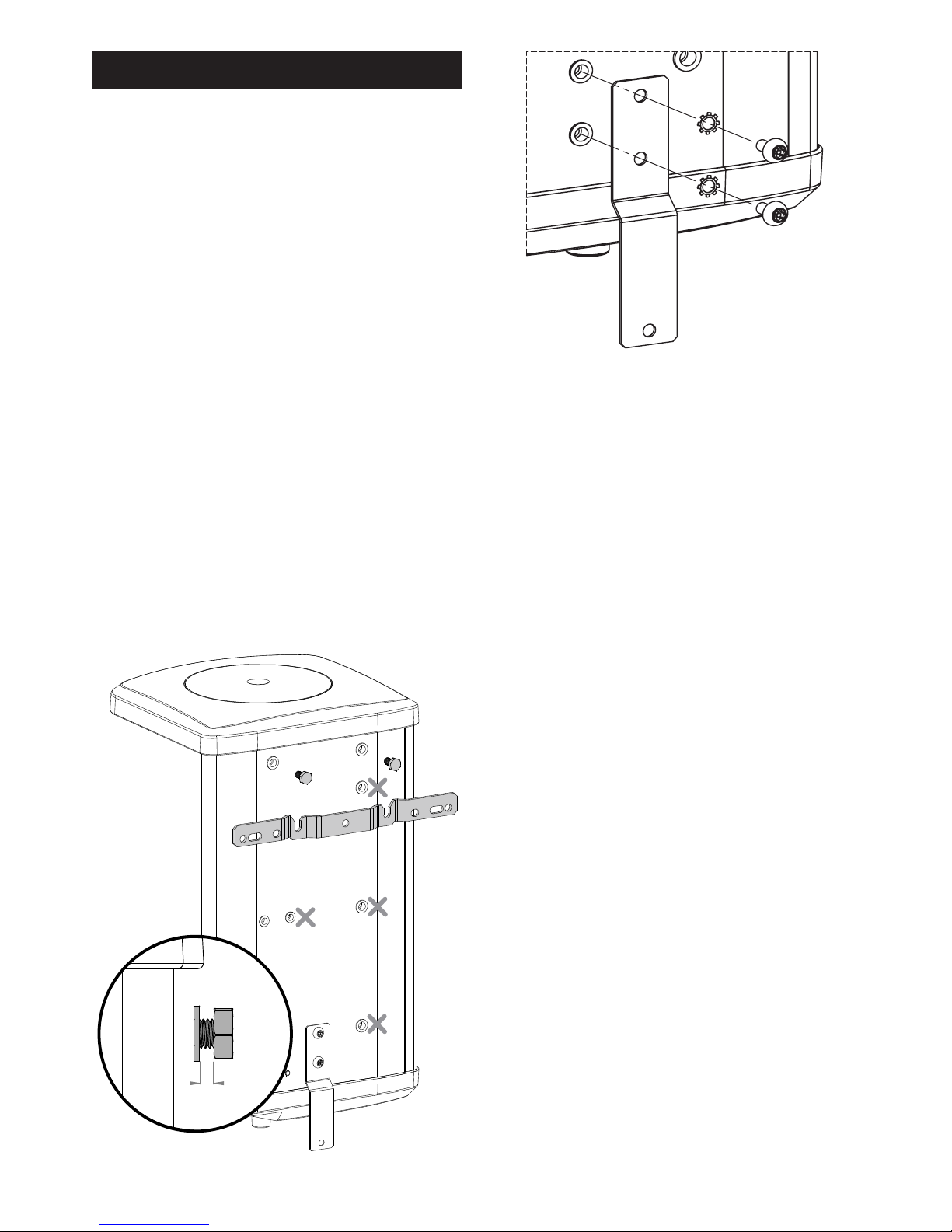
Mounting the water heater
The water heater should be mounted using the brackets
supplied following the steps stated below:
� The top bracket bolts will require mounting to the
appliance. Note the location of the bolt holes used
for the vertical appliances as well as which way up
the appliance should be mounted.
� The top bracket bolts should be screwed all the
way into the hole until they stop and stick out 8mm
as shown in gure 4 below.
� The bottom bracket will require mounting to the
casing as shown in gure 5 using the xings
supplied. This must be done before the appiance
is mounted on the wall
� Secure the top bracket to the wall using appropriate
xings. Ensure it is tted the correct way up.
� Locate the appliance top bracket bolts in the
corresponding slots in the wall bracket. Ensure
they are fully engaged and seat correctly (gure 4).
� Secure the bottom bracket to the wall.
Figure 4: Top Bracket
Figure 5: Bottom Bracket
8 ±1.5 mm
Page 11
11
6.2 Water connections
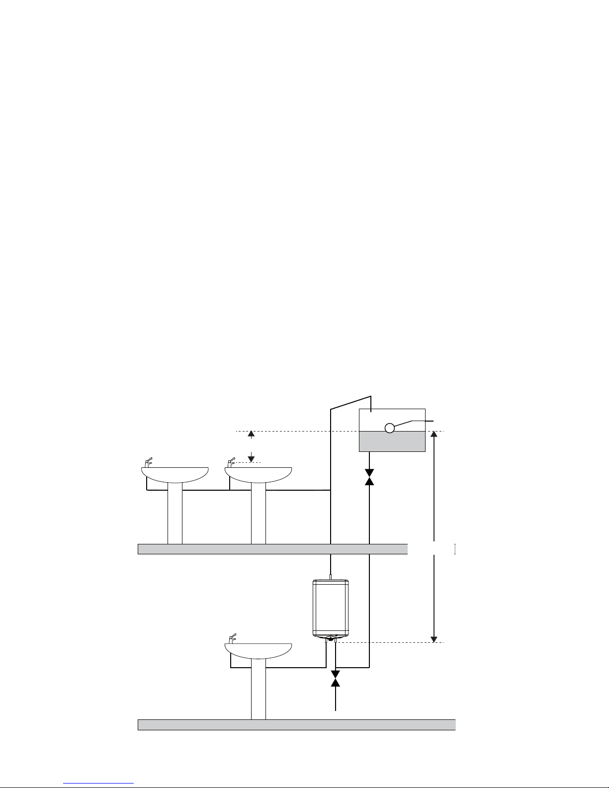
PLUMBING - CISTERN FED
� This method of installation is to be used at all
times when the outlet is connected to one or
more conventional taps. It is not recommended
for suppling a shower. Individual site demands
should be considered when choosing the number
of outlets to be served.
� A vent pipe must be connected to the outlet
connection of the heater.
� The vent pipe must have a minimum internal
diameter of 19mm.
� The vent pipe must be unobstructed, rise
continuously and be arranged to discharge over
the cold water feed cistern. DO NOT connect any
pressure relief device to the vent pipe of this water
heater.
� The cold water supply must be from a cold water
feed cistern complying with Byelaw 30. The
maximum head pressure must not exceed 20
metres (Water Regulations Schedule 2, section 7,
paragraph 16).
� It is recommended that an WRC Listed isolating
valve is tted on the cold water supply to the heater.
A drain cock should be tted on the inlet pipe to the
heater at a level lower than the appliance to allow
draining for maintenance.
� The inlet must not be connected directly to the cold
water mains supply.
� The Vent Pipe should be connected to the top of
the heater using a 1/2" BSP connection.
DRAIN
COCK
VENT
PIPE
CISTERN TANK
ISOLATING
VALVE
MINIMUM HEAD
4 METERS
MAXIMUM HEAD
20 METERS
Figure 8: Typical cistern fed installation
Page 12

12
� Check that the electrical supply is of sufcent
current rating and voltage, see Technical Data
page 5.
� A 2 metre length of exible cable is supplied
factory tted. The cable specication is H05VV-F
3G 2.5mm2. If replacing or extending the same
specication of cable should be used.
� The exible cable must be wired into an
appropriately fused switched spur.
� The conductor sheaths are colour coded as follows:
Green and Yellow EARTH
Brown LIVE (L)
Blue NEUTRAL (N)
WARNING
� Disconnect from the mains electrical
supply before removing any covers.
� Never attempt to replace the
immersion heater other than with the
recommended immersion heater.
� DO NOT bypass the thermal cut-out
in any circumstances. Ensure the two
spade terminations on the wires from
the thermostat and thermal cut-out are
pushed rmly into the corresponding
terminations on the element plate
assembly.
� All electrical wiring should be carried
out by a competent electrician and be
in accordance with the latest I.E.E,
Wiring Regulations.
� Each circuit must be protected by a
suitable fuse and double pole isolating
switch with a contact separation of at
least 3mm in both poles.
� DO NOT operate the immersion heater
until the appliance has been lled with
water.
6.3 Electrical connections
Page 13

13
7.1 General
WARNING
DO NOT operate the immersion until the
water heater has been lled with water.
7.2 Checklist before commissioning
� Check that all installation and vent pipe
requirements have been met.
� Check all water connections are tight.
� Check all electrical connections are tight.
� Check all earth bonding links are connected, tight
and un-damaged.
� Check earth continuity, short circuits, polarity and
resistance to earth.
7.3 Commissioning procedure
Cistern fed installation
� Open the highest hot outlet fed by the appliance.
� Turn on the cold water supply from the cold water
cistern
� Allow the appliance to ll until water discharges
from the hot outlet.
� Leave running to purge air and ush pipework
� Open any other hot outlets to purge air. 8.1
7. Commissioning
WARNING
� If the appliance is to be left unused
following installation and commissioning
e.g. unoccupied properties, the
appliance should be drained or regularly
ushed through with fresh mains water
once a week.
� When placing the appliance into service,
the procedure for lling the appliance
and the system checks detailed above
should be carried out.
Page 14
14
8. Operation
8.1 General
� The appliance stores water at the temperature set
on the internal adjustable thermostat. This can be
set to give temperatures in the range 10°C to 70°C.
The factory set temperature is set at 54°C.
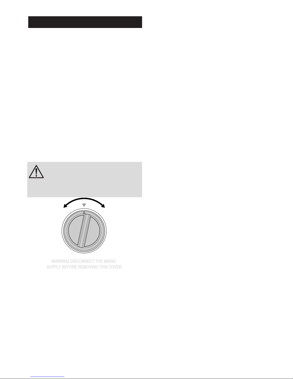
� The temperature control is underneath the cover,
please see gure 9, page 15 on how to remove.
� Turn the adjustment knob clockwise to set hotter,
or counterclockwise to set cooler.
� In hard water areas it is advised that the maximum
temperature is restricted to prevent build up of
scale.
� To avoid risk of freezing when the heater is not
in use for long periods during the winter months,
do not switch off the electrical supply and set the
thermostat to its minimum position. N.B. This will
not protect other system pipework.
� The indicator light will be illuminated when the
appliance is heating.
� To ensure the appliance continues to operate at
its optimum performance it should be periodically
maintained in accordance with the instructions
given under the section headed MAINTENANCE.
WARNING
� DO NOT bypass the thermal cut-out in
any circumstances.
COLD
HOT
Figure 9: Temperature control
� To ensure the appliance continues to operate at
its optimum performance it should be periodically
maintained in accordance with the instructions
given under the section headed MAINTENANCE.
Page 15
15
9. Maintenance
9.1 Standard inspection & maintenance
operations
To ensure the continued safe and efcient operation of
the appliance, it should be regularly maintained.
Maintenance should be carried out by a competent
person and any replacement parts used should be
authorised Heatrae Sadia spare parts.
It is recommended that maintenance is carried out
annually and should include the checks detailed in the
section below.
In hard water areas the appliance will require periodic
descaling to ensure efcient operation. To descale the
appliance:
Descaling immersion heater
CAUTION
Be careful when removing the immersion
heater as some water will be left in bottom
of appliance.
DO NOT use a sharp implement as damage
to the element surface could be caused.
DO NOT scrape element clean.
� Turn off the cold water supply and isolate the
electrical supply to the appliance.
� Attach a hosepipe to the drain cock having sufcient
length to take water to a suitable discharge point
below the level of the appliance.
� Open a hot tap close to the appliance (cistern fed
installations) and open drain cock to drain the
appliance.
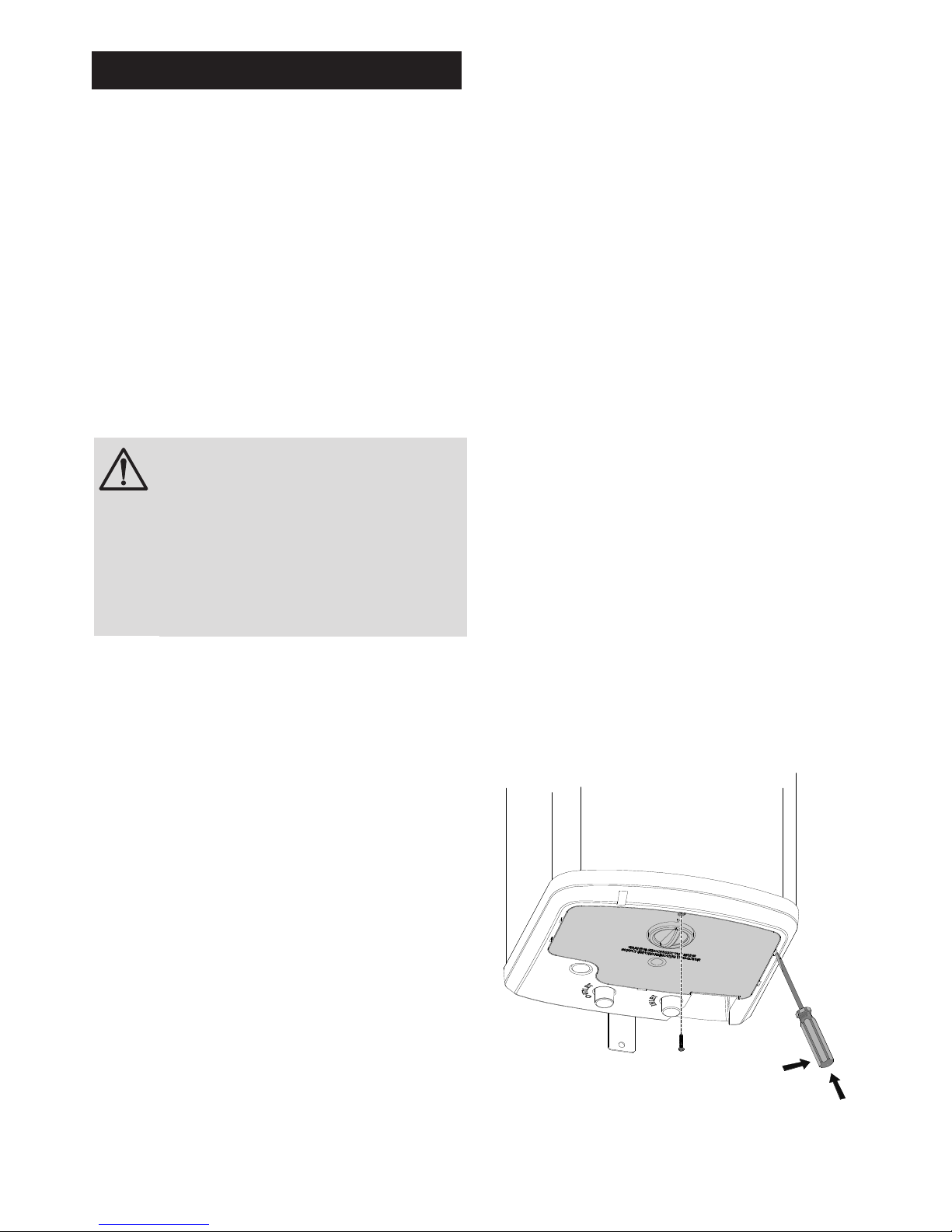
� When empty, open the cover to the immersion
heater housing. Remove the securing screw then
release the cover by carefully inserting a at bladed
screwdriver into the slots around the cover and
gently levering outwards until the catches release
(see Figure 9, page 15).
� Disconnect wiring from immersion heater terminals.
� Carefully remove the thermostat and thermal cut-out
capilliary sensors from the pocket on the immersion
heater.
� Place a suitable receptacle beneath the immersion
heater to collect any water left in the appliance.
� Unscrew immersion heater bolts and remove
immersion heater from the water heater.
NOTE: Over time the immersion heater gasket may
become stuck to the mating surface. To break the seal
there is a seperate threaded hole in the plate. Screw
one of the removed bolts into this hole to help remove
element.
� Carefully remove any scale from the surface of
the element. Remove any loose scale from the
appliance interior.
� Ensure sealing surfaces are clean and seals are
undamaged, if in doubt t a new gasket.
� Replace immersion heater ensuring correct
orientation. One of the bolt holes uses a larger bolt
to ensure the correct orientation.
� Tighten bolts.
� Fill appliance with water and check for leaks.
� Replace thermostat and thermal cut-out capillary
sensors into pocket on the immersion heater,
ensure that the thermostat is inserted rst followed
by the cut-out (see gure 2, page 7 to identify).
Ensure they are pushed fully into the pocket and
the capillary tubes are not kinked or damaged.
� Reconnect wires from the thermostat onto element,
ensuring that the terminals are correctly engaged.
� Reconnect the earth wires to the earth stud.
� Rell the appliance. When water issues from the
hot tap or spout allow to run for a short while to
purge any air and ush through the pipework.
Open successive hot taps served by the appliance
to purge any air. With all hot outlets closed check
all joints for leaks.
� Close immersion heater housing cover ensuring
the catches are pushed fully home until they
"snap" into place. Secure by replacing the screw
previously removed.
Figure 10: Cover removal
Page 16
16
10. Troubleshooting
10.1 Fault nding
Important
� Servicing should only be carried out by competent
persons in the installation and maintenance of
water heating systems.
� Any spare parts used MUST be authorised parts.
� Disconnect the electrical supply before removing
any electrical equipment covers.
� NEVER bypass any thermal controls.
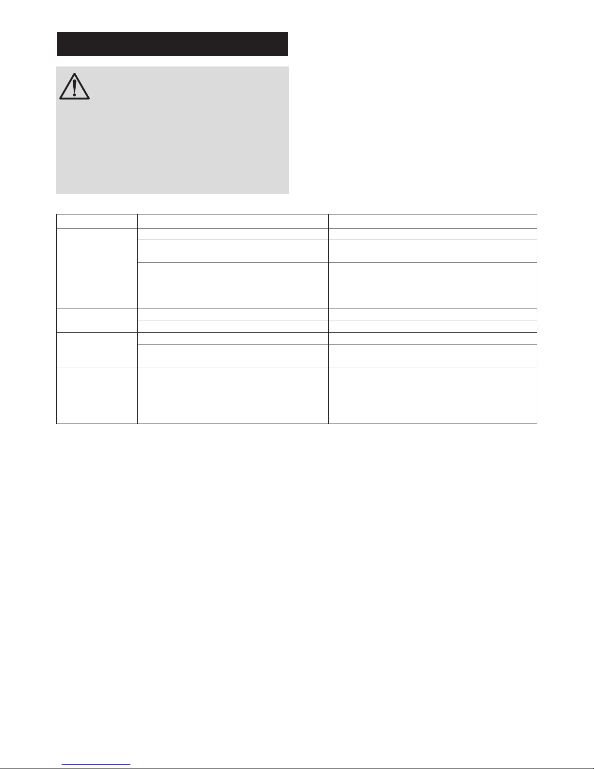
� The Fault Finding Chart (table 5, below) will enable
operational faults to be identied and their possible
causes rectied.
WARNING
DO NOT tamper with any of the safety
valves or controls supplied with the water
heater as this will invalidate any warranty.
Water contained in the water heater may
be very hot, especially following a thermal
control failure. Caution must be taken when
drawing water from the water heater.
Table 5: Fault nding chart
Spare Parts
A full range of spare parts are available for the
appliance range (table 6, page 20). Refer to the
technical data label on the appliance to identify the
model installed and ensure the correct part is ordered.
You will need to quote the serial number, which is
printed on the data label.
FAULT POSSIBLE CAUSES ACTION
Water not heating Electrical supply fault. Check electrical supply.
Thermal cut-out tripped. Check cut-out, if operated reset and check
thermostat operation. If necessary replace.
Thermostat fault. Check thermostat operation, replace if necessary.
Element fault. Check element for circuit continuity and insulation
resistance. If faulty replace.
No water ow -
General
Cold water supply not turned on. Check mains water supply is on.
Blockage in cold water supply. Check for obstructions.
No water ow
- Cistern Fed
installations
Blockage in tapset. Check for obstructions.
Cistern tank empty. Check water supply to cistern tank is turned on.
Check operation of cistern oat valve.
Water ows
gradually reduces
- Cistern Fed
installations
Cistern not lling as fast as outlet ow rate. Check water supply to cistern tank is turned on
and that the inlet ow rate is equal to outlet ow
rate. Check operation of cistern oat valve.
Vent pipe blockage. Check vent pipe for obstructions, clear as
necessary.
Page 17

17
11. Warranty
11.1 General
The Express warranty provides a high level of
customer support and peace of mind in the unlikely
event that a problem arises from a manufacturing
defect. It is supported by a nationwide team of eld-
based engineers and our own call centre.
The warranty covers appliances installed in domestic
and commercial properties for the following periods:
� Stainless steel storage vessel and connections - 2
years
� Cold water control valves supplied with the
appliance - 2 years
� Immersion heater assembly - 2 years
� Electrical controls as factory tted to the appliance
- 2 years
The warranty periods apply from the date of purchase
and include both parts (where supplied by Heatrae
Sadia) and labour.
This warranty is valid for installations within the United
Kingdom. For installations in the Republic of Ireland
please contact Potterton Myson (Ireland) Limited on
+353 (0) 1 4590870 for warranty terms and conditions
applicable. For installations outside of the United
Kingdom and the ROI please contact Heatrae Sadia
Export on +44 1603 420271 for warranty terms and
conditions applicable.
This warranty does not affect your statutory rights.
11.2 Warranty conditions
The warranty is given provided that the following
conditions have been met:
� The appliance has been installed by a competent
installer in accordance with the instructions
contained in this manual and in compliance with
all relevant laws, guidance, codes of practice and
regulations in force at the time of installation.
� The appliance has not been modied or tampered
with in any way, other than by Heatrae Sadia or
authorised engineers.
� The appliance or any part or parts of the appliance
(whether factory tted or otherwise) have not been
repaired or replaced other than by a Heatrae Sadia
authorised engineer and any replacement parts
used on the appliance are authorised Heatrae
Sadia spare parts.
� The appliance has not been subject to damage
caused by the build up of scale.
� The appliance has not been subjected to frost or
freezing temperatures.
� The appliance has not been subjected to misuse or
neglect.
� The appliance has not been subject to wilful or
accidental damage caused by your negligence.
� Regular maintenance has been carried out by a
competent person or a Heatrae Sadia authorised
engineer in accordance with the maintenance
requirements set out in this manual.
� The appliance has not been installed in areas
where the water supply contains chloride levels
which exceed 250mg/l.
� The appliance is registered within 60 days of
purchase. This can be done by telephone, online
or by using the registration form supplied with the
appliance.
� The appliance has not been affected by any cause
beyond our reasonable control including, without
limitation: an act of God, explosion, ood, re or
accident; war or civil disturbance; strike, industrial
action or stoppages of work; any form of government
intervention; a third party act or omission including
theft or malicious damage; failure by you to give
us a correct delivery address or notify us of any
change of address.
11.3 Water supply requirements
This appliance must only be used for the storage
of wholesome water. The storage of water from
supplies not meeting the requirements of the Water
Supply (Water Quality) Regulations will invalidate the
warranty. Any disinfection procedure must be carried
out in accordance with BS EN 806 and the complete
system be thoroughly ushed following application of
any disinfection solution.
11.4 Claims under warranty
In order to claim against the warranty the following
should be noted:
� Defects should be reported to Heatrae Sadia as
soon as you are aware of them. Please report any
defect to Heatrae Sadia by contacting 0344 871
1535.
� Evidence of purchase (for example a receipt) and
date of supply is submitted when making a claim.
� Access should be available, at reasonable times
and upon reasonable notice, to the appliance to
allow any inspection, repair or replacement.
� The appliance should not be removed from its
place of installation so a Heatrae Sadia authorised
engineer can assess the complete installation.
11.5 Exclusions
The following exclusions apply:
� Any third party repair or replacement costs, unless
those costs have been agreed and authorised by
Heatrae Sadia in writing prior to incurring those
costs, will not be met.
� Heatrae Sadia accepts no liability for any third
party damage, any indirect and consequential
losses and any loss of earnings, loss of business,
or losses in relation to stress and inconvenience,
howsoever caused.
Page 18

18
12. Decommissioning
12.1 Decommissioning procedure
� Isolate electrical supplies and make safe
� Isolate the water supply
� Drain the appliance
� Remove appliance
� Cap pipework
Environmental information
Products are manufactured from many recyclable
materials. At the end of their useful life they should be
disposed of at a Local Authority Recycling Centre in
order to realise the full environmental benets.
Insulation is by means of an approved CFC/HCFC free
polyurethane foam with an ozone depletion factor of
zero.
WEEE Declaration
Disposal of Waste Equipment by Users in Private
Households in the European Union.
This symbol on the product indicates that this product
must not be disposed of with your other household
waste. Instead, it is your responsibility to dispose of
your waste equipment by handing it over to a designated
collection point for the recycling of waste electrical
equipment. The separate collection and recycling of
your waste equipment at the time of disposal will help
to conserve natural resources and ensure that it is
recycled in a manner that protects human health and
the environment. For more information about where
you can drop off your waste equipment for recycling,
please contact your local city ofce, your household
waste disposal service or the company where this
product was purchased.
Page 19

19
Page 20
20
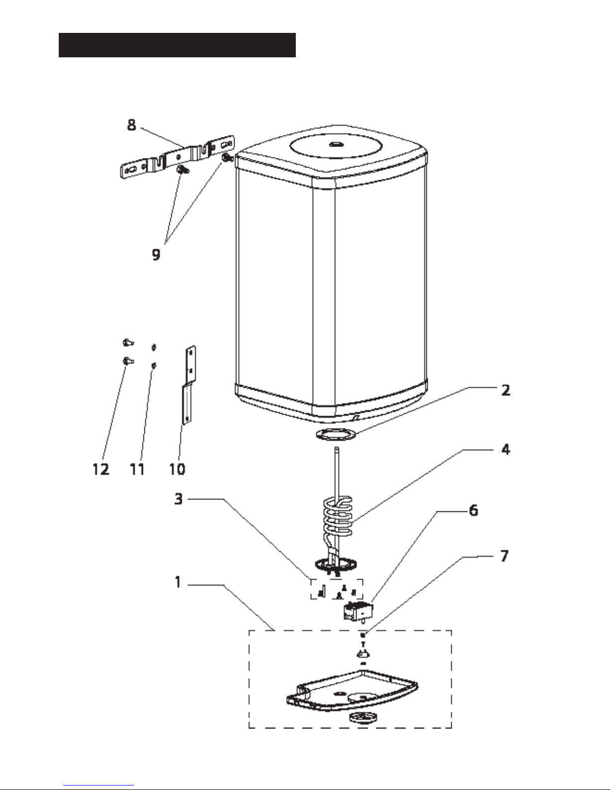
13. Spare parts
Figure 10: Spare parts
Page 21

21
13.1 Spare parts list
Item Description Part Number
1 ELECTRICAL COVER WHITE SMALL + KNOB 7037703
2 IMMERSION HEATER GASKET 95611708
3 IMMERSION HEATER FIXINGS 7037707
4 IMMERSION HEATER ASSEMBLY - 3.0kW 7037711
5 INDICATOR LIGHT BBSC (not shown) 7037724
6 THERMOSTAT / THERMAL CUT OUT BBSC FOR KNOB CONTROL 30/50 7037726
7 THERMOSTAT / THERMAL CUT OUT ADAPTER 7037738
8 WALL BRACKET VERTICAL (NO BOLTS) 7037733
9 FIXING BRACKET BOLT KIT (Appliance SIDE ONLY) 7037737
10 BRACKET FIXING BOTTOM 7034212
11 M8 EXT TOOTH LOCK WASHER A2 SS 7034210
12 BOLT SECURITY TORX M8X16 7034211
13 COMPRESSION NUTS & OLIVES (NOT SHOWN) 95607253
Table 6: Spares table
Page 22

22
Page 23

23
Page 24
Please follow us online:
Electric Water Heating Co.
2 Horsecroft Place
Pinnacles
Harlow
Essex CM19 5BT
Tel: 0845 0553811
E-Mail: [email protected]
SPD
Special Product Division
Units 9 & 10
Hexagon Business Centre
Springfield Road
Hayes
Middlesex UB4 0TY
Tel: 020 8606 3567
Parts Center
Tel: 0344 292 7057
www.partscenter.co.uk
Newey & Eyre
Unit 3-5 Wassage Way
Hampton Lovett Ind. Estate
Droitwich, Worcestershire
WR9 0NX
Tel: 01905 791500
Fax: 01905 791501
UK Spares Ltd
Unit 1155
Aztec West
Almondsbury
Bristol BS32 4TF
Tel: 01454 620500
Alternatively contact your
local supplying merchant
or wholesale branch or use
our online stockist finder at
www.interpartspares.co.uk
PRODUCT RANGE
Full specification details on all our products are available to download from our website.
To support our corporate responsibility and sustainability charters and reduce our
printed material we encourage you to download product brochures from our website.
In designing these files we have taken into account the need to access data on screen.
If you would like to receive a printed copy of our full product catalogue please call
our literature hotline on 01603 420127.
Heatrae Sadia Heating may introduce modifications to their products from time
to time. Consequently, the details given in this brochure are subject to alteration
without notice.
OUR NATIONWIDE NETWORK OF CUSTOMER SUPPORT ENGINEERS
Heatrae Sadia has its very own dedicated nationwide network of highly trained
customer support engineers so you can have peace of mind that we’re always
here to help.
SPECIFICATION ADVICE HOTLINE
t | 01603 420220 e | specifi[email protected]
AFTER SALES SERVICE
t | 0344 871 1535 e | [email protected]
w | heatraesadia.com
MADE IN
THE UK
24
2
2 YEAR
INNER
CONTAINER
WARRANTY
7037326_issue_03
 Loading...