

Heat-N-Glo SL-550TRS-AUC Installation And Operation Instructions Manual

INSTALLATION AND OPERATION
INSTRUCTIONS
MODEL: SL-550TRS-AUC
AUSTRALIAN GAS ASSOCIATION APPROVED
Approval Number 5666
THIS MANUAL MUST BE USED FOR INSTALLATION AND RETAINED
BY HOMEOWNER FOR OPERATION AND MAINTENANCE.
HEAT-N-GLO, a division of Hearth Technologies Inc.
20802 Kensington Boulevard, Lakeville, MN 55044 USA • 1-888-427-3973
This product is covered by one or more of the following patents: (United States) 4,112,913; 4,408,594; 4,422,426; 4,424,792; 4,520,791; 4,793,322;
4,852,548; 4,875,464; 5,000,162; 5,016,609; 5,076,254 5,191,877; 5,218,953; 5,328,356; 5,429,495; 5,452,708; 5,542,407; 5,613,487; (Australia)
543790; 586383; (Canada) 1,123,296; 1,297,746; 2,195,264; (Mexico) 97-0457; (New Zealand) 200265; or other U.S. and foreign patents pending.
347-900C 9/02
1
INSTALLATION AND OPERA TION INSTRUCTIONS
PLEASE READ THIS MANUAL BEFORE INSTALLING
AND USING THIS APPLIANCE.
MODEL SL-550TRS-AUC
IS AUSTRALIAN GAS ASSOCIATION
APPROVED FOR NATURAL GAS OR
PROPANE AS A BALANCED FLUE
HEATER.
Refer to the appliance data plates for gas
consumptions and pressures.
Installation of this appliance should only be
carried out by an authorized person in accordance with the manufacturer's instructions. All relevant codes and regulations laid
down by the gas piping authorities, municipal building regulations, electrical wiring
regulations and the requirements of the AGA
Gas Installation Code must be observed.
This appliance and its components are
tested and safe when installed in accordance with this Installation Manual. Report
to your dealer any parts damaged in shipment, specifically check glass condition. The
gas logs and flue system components are
in separate packages. Read all instructions
before starting installation and follow these
instructions carefully during installation to
ensure maximum benefit and safety. Failure to follow them will void your warranty and
may present a fire hazard.
The Heat-N-Glo, a division of Hearth Technologies Inc. warranty will be voided by, and
Heat-N-Glo, a division of Hearth Technologies Inc. disclaims any responsibility for the
following actions:
• Installation of any damaged heater or
flue system component
• Modification of the heater or balanced
flue system installation other than as
instructed by Heat-N-Glo, a division of
Hearth Technologies Inc.
• Improper positioning of the gas logs or
the glass door
• Installation and/or use of any component
part not manufactured or approved by
Heat-N-Glo, division of Hearth Technologies Inc., not withstanding any independent testing laboratory or other
party approval of such component part
or accessory.
IMPORTANT: Read all instructions carefully before starting installation.
Failure to follow these installation instructions may result in a possible fire
hazard and will void the warranty. Save this Manual for future reference.
Copyright 2002
Heat-N-Glo, a division of Hearth Technologies Inc.
20802 Kensington Boulevard, Lakeville, MN 55044
Printed in U.S.A.
2

TABLE OF CONTENTS
1.0 Installation Instructions........................................................................................ 5
u
1.1 Introduction.................................................................................................. 6
1.2 Flue System Approvals and Installation ........................................................ 8
1.3 Connecting the Gas Supply........................................................................ 21
1.4 Fan ........................................................................................................... 21
1.5 Finishing ................................................................................................... 23
1.6 Installer Testing .......................................................................................... 24
1.7 Log Placement .......................................................................................... 25
2.0 Operating Instructions ...................................................................................... 27
2.1 Safety and Lighting Information .................................................................. 27
2.2 Safety Information...................................................................................... 28
u
2.3 Lighting Instructions ................................................................................... 29
2.4 Fan Operation ........................................................................................... 30
3.0 Servicing and Maintenance.............................................................................. 30
3.1 Removal of Covers for Servicing................................................................ 31
3.2 Removal of Components for Service.......................................................... 31
3.3 Parts Replacement.................................................................................... 31
3.4 Adjustments and Replacement Parts ......................................................... 31
u
3.5 Troubleshooting......................................................................................... 32
u
4.0 Replacement Parts .......................................................................................... 36
Limited Warranty.............................................................................................. 38
u = Contains updated information.
3
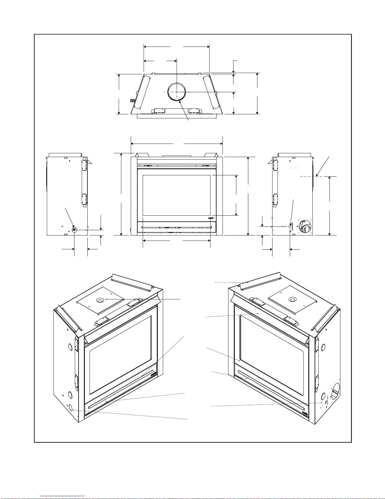
12-7/8
1/2
23-3/8
6-7/8
3-1/2
31
16-1/8
26-3/8
36
(REAR FLUE
CENTER LINE)
327[ ]
25-3/4
653[ ]
14[ ]
GAS
LINE
ACCESS
2-1/8
55[ ]
5
129[ ]
15-7/8
402[ ]
32-1/2
827[ ]
6 5/8 (168)
(TOP FLUE COLLARS)
913[ ]
671[ ]
8-3/4
223[ ]
408[ ]
[ ]
789
16-3/8
415[ ]
90[ ]
ELECTRICAL
ACCESS
174[ ]
COLLARS
8 5/8 (219)
593[ ]
u
FIGURE 1. Diagram of SL-550TRS-AUC
TOP STANDOFFS
FLUE COLLARS
HOOD
DATA BADGE
& LABELS
DRESS
GUARD
BOTTOM GRILLE
COVER
GAS
CONTROLS
ELECTRICAL
ACCESS
GAS LINE
ACCESS
4
1.0 INSTALLATION INSTRUCTIONS
1/2” MIN. (13mm)
C
3” MIN. (76mm)
BDE
In planning the installation for the heater it is necessary to determine where the unit is to be installed, the
type of flue system to be used (straight out, corner, or
elevated), and whether optional accessories (wall
switch or remote control) are desired. Gas supply piping should also be planned. Refer to the appliance data
plate on the base pan of the heater for all gas pressures and input rate information.
The heater can be mounted on any of the following
surface:
1. A flat surface (minimum 6mm base).
2. Four (4) corner supports.
(Example: Four (4) concrete masonry blocks). These
supports must be positioned so they contact all four
(4) perimeter edges on the bottom of the unit.
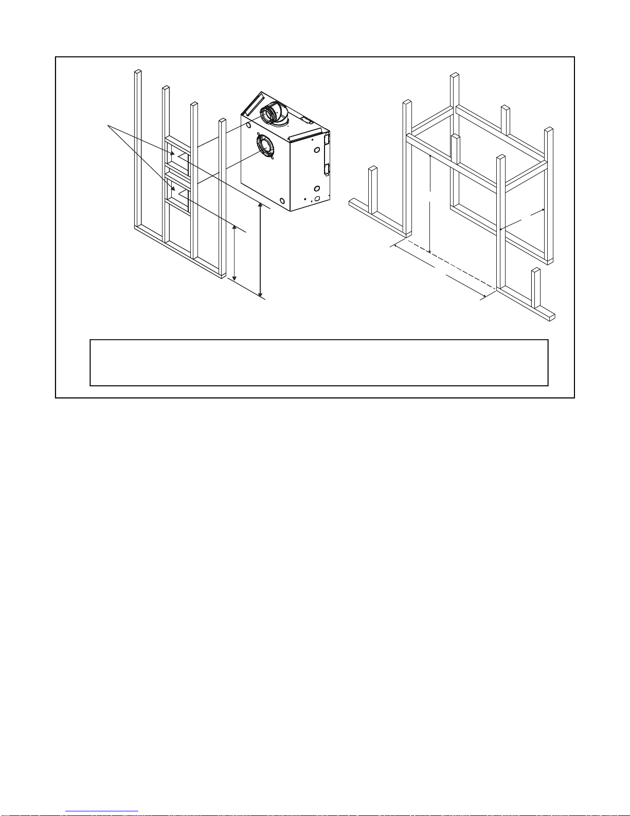
Heater framing can be built before or after the heater is
set in place. Framing should be positioned to accommodate wall covering and heater facing material. The
heater framing should be constructed of 2" X 4" (51 x
102mm) lumber or heavier. The framing headers may
rest on the heater standoffs. Refer to Figure 2 and Figure 3 for heater and framing reference dimensions.
Minimum Clearances
from the Fireplace to Combustible Materials
Inches mm
Glass Front ......................................36 ........ 914
Floor ..................................................0........... 0
Rear ................................................. 1/2 ........ 13
Sides ............................................... 1/2 ........ 13
Top .................................................1 1/2 ....... 38
Ceiling* .............................................31 ........ 787
*The clearance to the ceiling is measured from the top
of the unit, excluding the standoffs (see Figure 27).
Minimum Clearances
from the Vent Pipe to Combustible Materials
Inches mm
Vertical Sections............... 1................. 25
Horizontal Sections
Top ...................................... 3................. 75
Bottom................................ 1................. 25
Sides .................................. 1................. 25
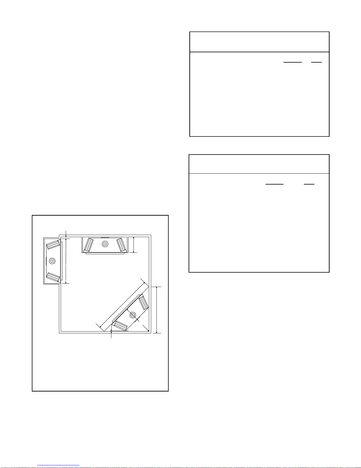
A
A B C D E
37 16 1/4 29 3/8 41 1/2 58 3/4
(940mm) (418mm) (746mm) (1054mm)(1492mm)
NOTE: DIMENSIONS SHOWN WITH THE SIDES, BACK
AND/OR CORNERS OF THE UNIT TOUCHING THE WALL.
Figure 2. Fireplace Dimensions, Locations, and
Space Requirements
At Wall Firestops
Top ................................... 2 1/2.............63.7
Bottom.............................. 1/2 ............... 13
Sides .................................. 1................. 25
For minimum clearances, see the direct vent termination clearance in Figures 19 and 24.
5
ABC
FLUE
FRAMING
HOLE
D
E
*NOTE: The center of
the framing hole is one
inch (254mm) above
the center of the
horizontal flue pipe.
Model A B C D E*
SL-550TRS-AUC 37" 33 1/2" 16 1/4" 36 1/2" 24 3/8"
(940mm) (851mm) (418mm) (927mm) (619mm)
u
FIGURE 3. Framing Dimensions
CAUTION: Measure heater dimensions, and verify
framing methods and wall covering details before framing construction begins.
1.1 INTRODUCTION
This model is designed to operate with all combustion air being siphoned from the outside of the building and all exhaust gases expelled to the outside of
the building.
WARNING: THIS UNIT IS NOT FOR USE WITH
SOLID FUEL.
These units MUST use the flue termination described
The framing headers may rest on
the fireplace stand-offs.
Framing should be constructed
of 2 X 4 lumber or heavier.
in the flueing section of the manual.
The control system for these models are a millivolt type.
It consists of a gas control valve/variable regulator, a
standing pilot/thermopile/thermocouple, a piezo ignitor, and an ON/OFF switch. The controls are located
behind the lower grille. Access to the controls is gained
by rotating the grille down. See Figure 1.
Minimum inlet gas supply pressure for purpose of input adjustment is 4.5 inches w.c. (1.13kPa) for natural
gas and 11 inches w.c. (2.75kPa) for propane. Manifold (outlet) pressures should be set at 3.5 inches w.c.
(.8kPa) for natural gas models and 9.6 inches w.c.
(2.40kPa) for propane models.
6

T = Flue terminal M = Gas meter Shading indicates prohibited
I = Mechanical air inlet P = Electricity meter or fuse box areas for flue terminals
a - Below eaves, balconies or other projections: MIN. CLEARANCE (mm)
Appliances to 50 MJ/h input ................................................................................................ 300
Appliances over 50 MJ/h input............................................................................................500
b - From the ground or above a balcony .....................................................................................300
c - From a return wall or external corner .....................................................................................500
d - From a gas meter (M)...........................................................................................................1000
e - From an electricity meter or fuse box (P) ............................................................................... 500
f - From a drain or soil pipe ........................................................................................................ 150
g - Horizontally from any building structure (unless appliance approved
for closer installation) or obstruction facing a terminal ......................................................... 500
h - From any other flue terminal, cowl, or combustion air intake...............................................500
j - Horizontally from an openable window, door, non-mechanical air
inlet, or any other opening into a building, with the exception of
sub-floor ventilation:
Appliances up to 150 MJ/h input.........................................................................................500
Appliances over 150 MJ/h input........................................................................................ 1500
k - From a mechanical air inlet, including a spa blower .........................................................1500
n - Vertically below an openable window, non-mechanical air
inlet or any other opening into a building, with the exception of ................................. See table
sub-floor ventilation ............................................................................................................ below
CLEARANCES 'n' (mm)
Space heaters All other appliances
Up to 50 MJ/h
input
150 500 1000 1500
NOTES: 1. All distances are measured vertically or horizontally along the wall to a point
in line with the nearest part of the terminal.
2. Prohibited area below electricity meter or fuse box extends to ground level.
3. See clause 5.13.6.6 for restrictions on a flue terminal under a roofed area.
4. See Appendix J, Figure J1(a) and J2(a) for clearances required from a flue
terminal to a LP Gas cylinder. A flue terminal is considered to be a source of ignition.
MINIMUM CLEARANCES REQUIRED FOR BALANCED FLUE TERMINALS
OR THE FLUE TERMINALS OF OUTDOOR APPLIANCES
FIGURE 4
UP to 50 MJ/h
input
Over 50 MJ/h &
up
to 150 MJ/h
7
Over 150 MJ/h
input
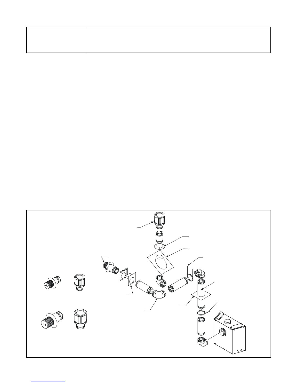
TABLE 1
TERMINATION
WALL FIRESTOP
ROOF FLASHING
HORIZONTAL PIPE
MODEL
SL-550TRS-AUC
DVK-01DA & SLK-01DA HORIZONTAL TERMINATION CAP
DVK-TVCD & SLK-991DA VERTICAL TERMINATION CAP
1.2 FLUE SYSTEM APPROVALS
These models have flue starting collars on both the top
and the back of the unit. Depending upon the installation, decide which ONE set of starting collars will be
used to attach the flue system. The starting collar sealing
cap must remain on the starting collar NOT used.
These models use SL-D-series direct flue components
when using the TOP flue collars and D-series direct
flue components when using the REAR flue collars.
WARNING: YOU MUST NOT MIX D-SERIES AND
SL D-SERIES COMPONENTS IN ANY FLUE
SYSTEM CONFIGURA TION.
Approved flue system components are labeled for
identification. NO OTHER FLUEING SYSTEMS OR
COMPONENTS MAY BE USED. Detailed installation
instructions are included with each flue termination kit
and should be used in conjunction with this manual. Figure
5 below shows flue system components and terminations.
Identifying Flue Components
The flue systems installed on this gas fireplace may
include one, two, or three 90° elbow assemblies. The
relationships of vertical rise to horizontal run in flue
configurations using 90° elbows MUST BE strictly
FLUE TERMINATION APPROVALS
adhered to. The rise to run relationships are shown in
the flueing drawings and tables on the next few pages.
If a 90° elbow is first attached to the unit, the maximum
horizontal run is 2 feet (610mm).
WARNING: THIS GAS APPLIANCE AND FLUE AS-
SEMBLY MUST FLUE DIRECTL Y TO THE OUTSIDE
AND MUST NEVER BE ATTACHED TO A CHIMNEY
SERVING A SEP ARATE SOLID FUEL BURNING APPLIANCE. EACH GAS APPLIANCE MUST USE A
SEPARATE FLUE SYSTEM-COMMON FLUE SYSTEMS ARE PROHIBITED.
CAUTION: UNDER NO CONDITION SHOULD
COMBUSTIBLE MATERIAL BE CLOSER THAN 3
INCHES (2 1/2 INCHES (64MM) AT WALL FIRESTOPS) FROM THE TOP OF THE PIPE OR 1-INCH
TO THE SIDES AND THE BOTTOM FOR HORIZONTAL
SECTIONS OF THIS FLUE SYSTEM. VERTICAL
SECTIONS OF THIS SYSTEM REQUIRE A MINIMUM OF 1-INCH (25MM) CLEARANCE TO COMBUSTIBLE MATERIALS ALL AROUND THE PIPE.
For alternative installations, other than depicted, contact your dealer for further information.
Refer to Figure 4 for required clearances to flue terminals.
VERTICAL
TERMINATION
HORIZONTAL
Flue system termination kits
D-SERIES
DVK-01D
SL D-SERIES
SLK-01DA
DVK-TVCD
SLK-991DA
FIGURE 5 Flue Components and Terminations
90 DEGREE
ELBOW
CEILING
FIRESTOP
Flue system components
STORM COLLAR
SUPPORT
PIPE LENGTH
WALL BRACKET
8
¾
”
m
)
5 ¾”
(146mm)
DV-90
D
(18
8 ½
2
16mm)11 5/8(295mm
)
/8 (219mm
)
1
5/16 (303mm
)
7 3
7
m
/
D
8
m
V-4
6 5/3
2
(
156
m
m
)
(
5 7
/
(14
8
9
m
m
)
)
8 5
11
8
D
DV-
3
6
D
DV-12D
4
7
(
1
¾”
.2m
)
(
908
35
m
DV-09D
11 ¾”
(298mm)
8 ¾”
DV-06D
(222mm)
NOTE: PIPES OVERLAP 1 3/8 INCHES (35MM) AT EACH JOINT.
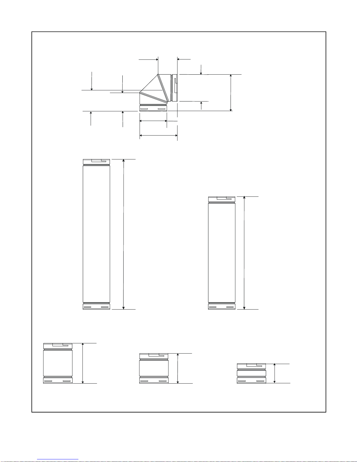
FIGURE 6 D-Series Balanced Flue Component Specifications
(5-inch (127mm) inner pipe / 8 5/8-inch (219mm) outer pipe)
9
6 ½
SL-17/24D
(432-610mm)
SL-12/17D
(165mm)
6 3/8
(162mm)
6 5/8
(168mm)
6 3/8
(162mm)
SL-90D
6 ½
(165mm)
9 5/8
(244mm)
9 5/8
(244mm)
5 ¾
(146mm)
(222mm)
8 ¾
SL-06D
6 5/8
(168mm)
(305-432mm)
12-17
11 ¾
(298mm)
(603mm)
23 ¾
SL-12D
35 ¾
(908mm)
17-24
47 ¾
(1213mm)
SL-09D
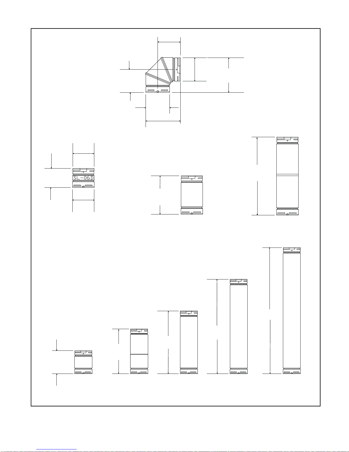
NOTE: PIPES OVERLAP 1 3/8 INCHES (35mm) AT EACH JOINT.
FIGURE 7 SL D-Series Balanced Flue Component Specifications
(4-inch (102mm) inner pipe / 6 5/8-inch (168mm) outer pipe)
SL-24D SL-36D SL-48D
10
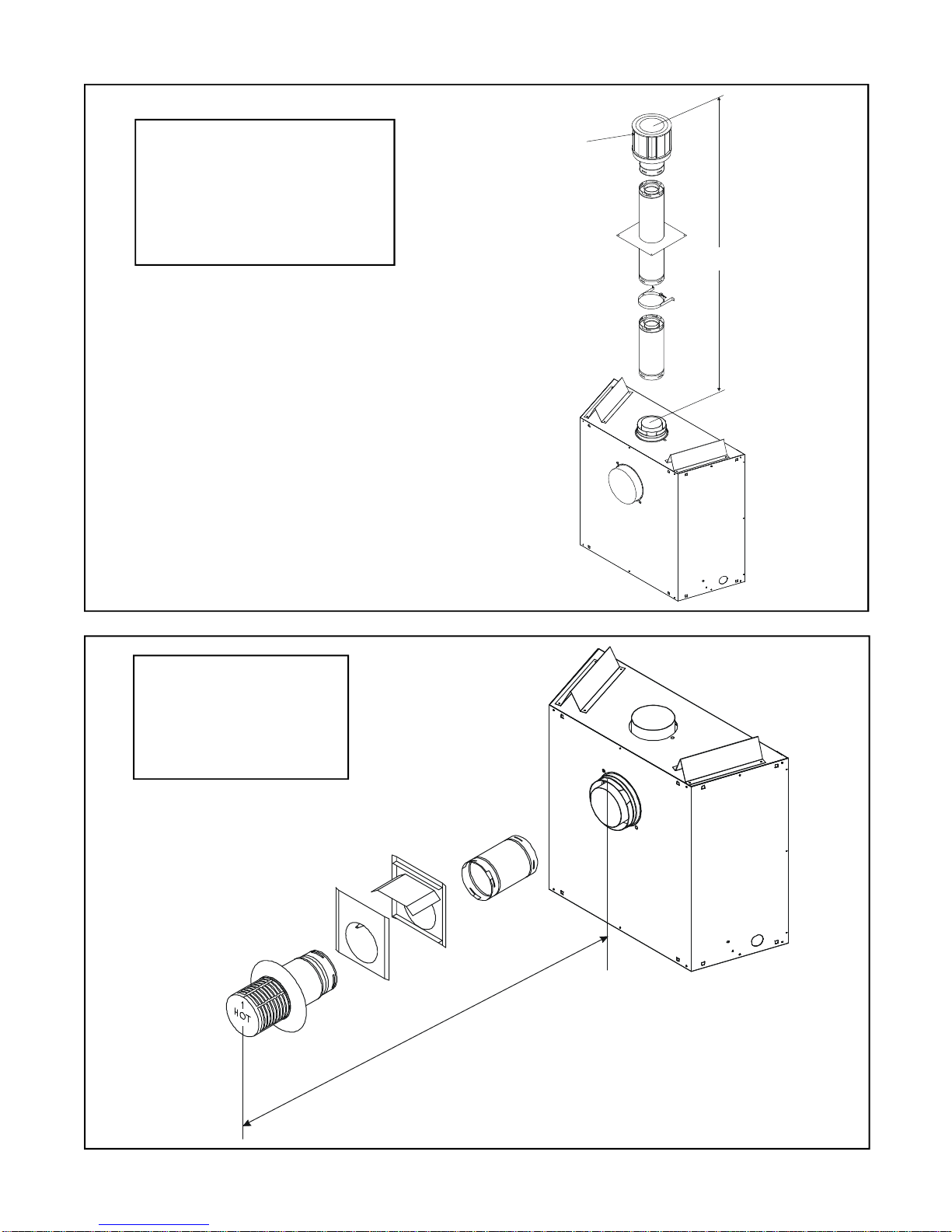
FIGURE 8
V
VERTICAL FLUEING
V
FT. (M)
30' MAXIMUM (9.1M)
USE SL D-SERIES COMPONENTS ONL Y.
CAP
STRAIGHT OUT HORIZONTAL
FLUEING
H
Max. Run
24" (610mm)
H
USE D-SERIES COMPONENTS ONL Y.
FIGURE 9
11
USE SL D-SERIES
H
V
COMPONENTS
ONL Y.
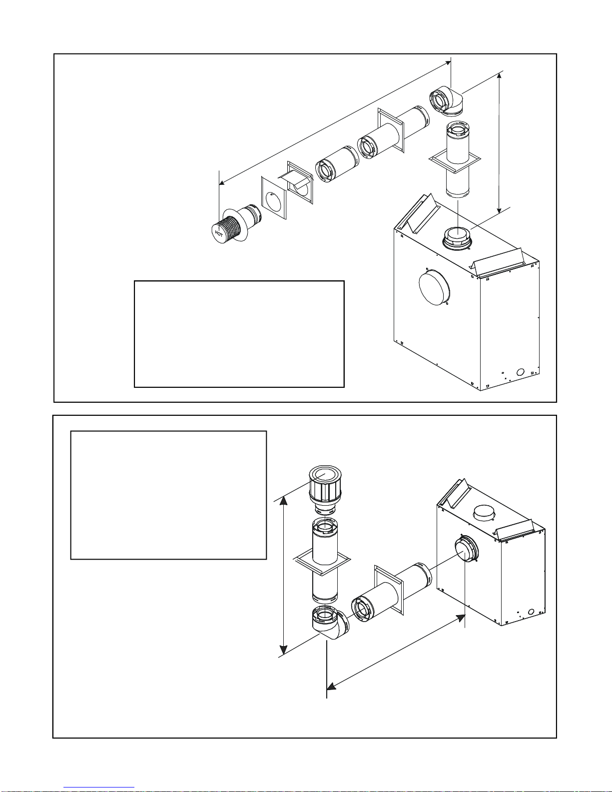
FLUEING WITH ONE (1) 90° ELBOW
V H
FT. (M) FT. (M)
1' MIN.(.3M) 2' MAX.(.6M)
2' MIN.(.6M) 4' MAX.(1.2M)
3' MIN.(.9M) 8' MAX.(2.4M)
4' MIN.(1.2M) 10' MAX.(3M)
V + H = 30' (9.1M)
FIGURE 10
FLUEING WITH ONE (1) 90o ELBOW
V (FT.) H (FT.)
1' MIN. (.3M) 3' MAX. (.9M)
2' MIN. (.6M) 6' MAX. (1.8M)
3' MIN. (.9M) 9' MAX. (2.7M)
4' MIN. (1.2M) 12' MAX. (3.7M)
V+H =30' MAX. (9.1M) H= 12' MAX. (3.7M)
USE D-SERIES
COMPONENTS
ONL Y.
FIGURE 11
V
H
12
 Loading...