

Heat-N-Glo ATS-AUST Installation And Operation Instruction Manual
INSTALLATION AND OPERATION
INSTRUCTIONS
MODEL: ATS-AUST
AUSTRALIAN GAS ASSOCIATION APPROVED
AGA Approval Number 5543
THIS MANUAL MUST BE USED FOR INSTALLATION AND RETAINED
BY HOMEOWNER FOR OPERATION AND MAINTENANCE.
HEAT-N-GLO, a division of Hearth Technologies Inc.
6665 W. Hwy 13 Savage, MN 55378, USA (612)890-8367
This product is covered by one or more of the following patents: (United States) 4,112,913; 4,408,594; 4,422,426; 4,424,792; 4,520,791; 4,793,322;
4,852,548; 4,875,464; 5,000,162; 5,016,609; 5,076,254 5,191,877; 5,218,953; 5,328,356; 5,429,495; 5,452,708; 5,542,407; 5,613,487; (Australia) 543790;
586383; (Canada) 1,123,296; 1,297,746; 2,195,264; (Mexico) 97-0457; (New Zealand) 200265; or other U.S. and foreign patents pending.
491-900-C 1/99

INSTALLATION AND OPERATION INSTRUCTIONS
PLEASE READ THIS MANUAL BEFORE INSTALLING AND USING THIS
APPLIANCE.
MODEL ATS-AUST IS AUSTRALIAN GAS ASSOCIATION APPROVED FOR
NATURAL GAS OR PROPANE AS A BALANCED FLUE HEATER.
Refer to the appliance data plates for gas consumptions and pressures.
Installation of this appliance should only be carried out by an authorized person
in accordance with the manufacturers instructions. All relevant codes and regulations laid down by the gas piping authorities, municipal building regulations,
electrical wiring regulations and the requirements of the AGA Gas Installation
Code must be observed.
This appliance and it's components are tested and safe when installed in accordance with this Installation Manual. Report to your dealer any parts damaged in
shipment, specifically check glass condition. The gas logs and flue system components are in separate packages. Read all instructions before starting installation and follow these instructions carefully during installation to ensure maximum benefit and safety . Failure to follow them will void your warranty and may
present a fire hazard.
The Heat-N-Glo Fireplace Products, Inc. warranty will be voided by , and Heat-NGlo Fireplace Products, Inc. disclaims any responsibility for the following actions:
• Installation of any damaged heater or flue system component
• Modification of the heater or balanced flue system Installation other than as
instructed by Heat-N-Glo Fireplace Products, Inc.
• Improper positioning of the gas logs or the glass door
• Installation and/or use of any component part not manufactured or approved by Heat-N-Glo Fireplace Products, Inc., not withstanding any independent testing laboratory or other party approval of such component part
or accessory.
IMPORTANT: Read all instructions carefully before starting installation. Failure to follow these instal-
lation instructions may result in a possible fire hazard and will void the warranty .
Save this Manual for future reference.
Copyright 1999, Heat-N-Glo Fireplace Products, Inc., 6665 W. Hwy 13, Savage, MN 55378 Printed in U.S.A.
1

TABLE OF CONTENTS
1.0 Installation Instructions.................................................................................... 7
1.1 Introduction............................................................................................... 7
1.2 Flue System ............................................................................................. 7
1.2.1 Flue System Approvals................................................................... 7
1.2.2 Connecting the Flue Pipe ............................................................... 8
1.3 Connecting the Gas Supply...................................................................... 8
1.4 Fan ........................................................................................................... 9
1.5 Surround Installation................................................................................. 9
1.6 Finishing ................................................................................................. 11
1.7 Log Installation ....................................................................................... 11
1.8 Installer Testing....................................................................................... 11
2.0 Operating Instructions ................................................................................... 12
2.1 Safety and Lighting Information .............................................................. 13
2.2 Safety Information................................................................................... 13
2.3 Lighting Instructions................................................................................ 14
2.4 Fan Operation......................................................................................... 15
3.0 Servicing and Maintenance........................................................................... 15
3.1 Removal of Covers for Servicing ............................................................ 16
3.2 Removal of Components for Service ...................................................... 16
3.3 Parts Replacement ................................................................................. 16
3.4 Adjustments and Replacement Parts ..................................................... 16
3.5 Troubleshooting...................................................................................... 17
4.0 Replacement Parts........................................................................................ 21
Limited Warranty............................................................................................ 24
2
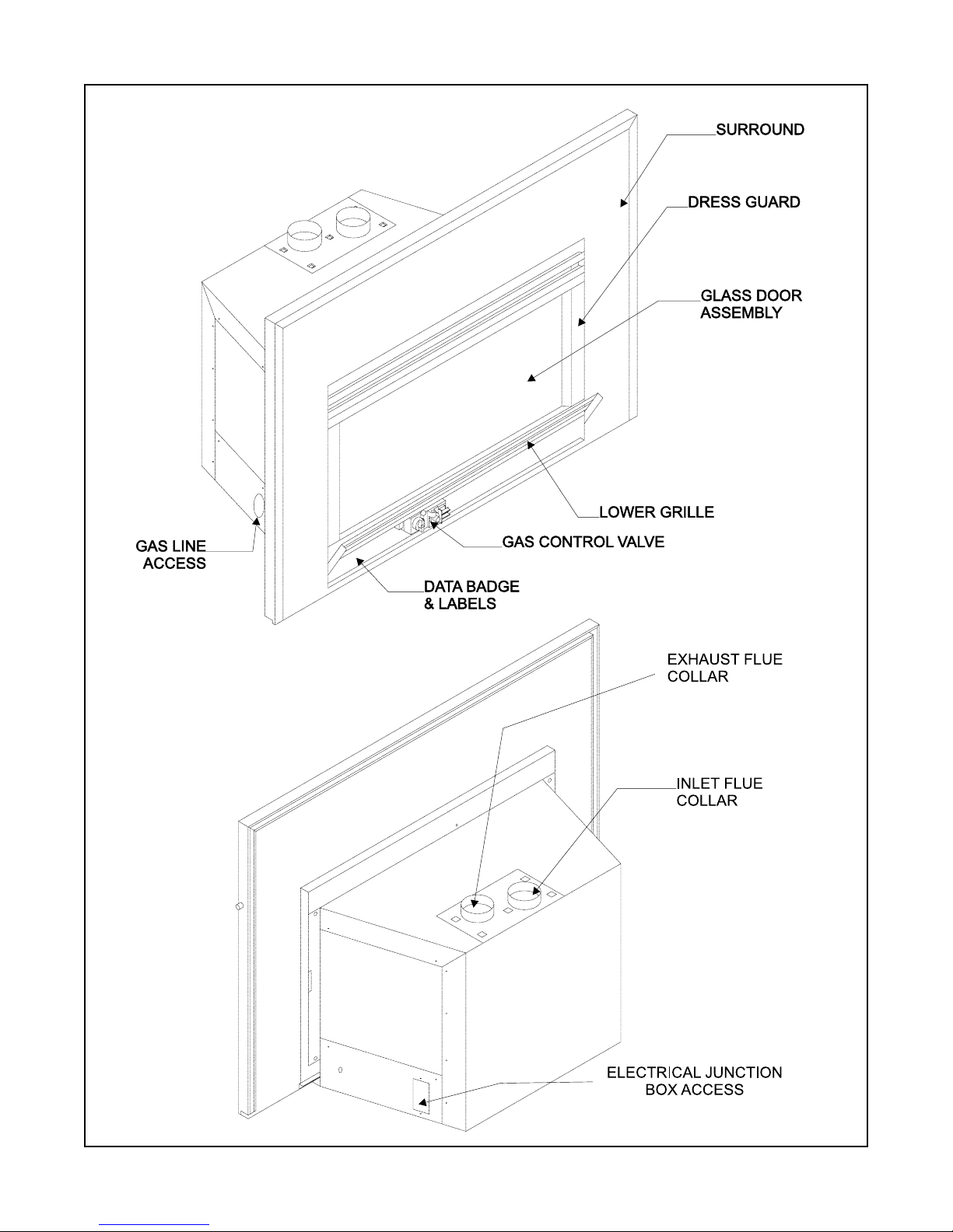
FIGURE 1
3
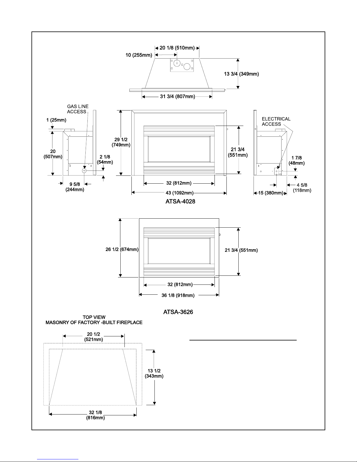
MINIMUM FIREPLACE OPENING
WIDTH: 32 1/8" (816mm)
DEPTH: 13 1/2" (343mm)
HEIGHT : 20 1/2" (521mm)
NOTE: If exhaust collar on insert and fireplace
damper do not line up, add 4 inches (102mm) to
minimum fireplace opening height to accommodate
bends in vent pipe.
FIGURE 2
4
MODEL FLUE TERMINATION APPROVAL
ATS-AUST SLK-991DA VERTICAL TERMINATION CAP
TABLE 1
WARNING: THE EXHAUST PIPE
MUST ONL Y BE CONNECTED TO THE
EXHAUST STARTING COLLAR OF
THE UNIT AND THE CENTER COLLAR
OF THE TERMINA TION CAP .
THE INLET AIR PIPE MUST ONL Y BE
CONNECTED TO THE INLET AIR
COLLAR OF THE UNIT AND A TT ACHED
TO THE INLET AIR COLLAR OF THE
TERMINA TION CAP .
FIGURE 3
5
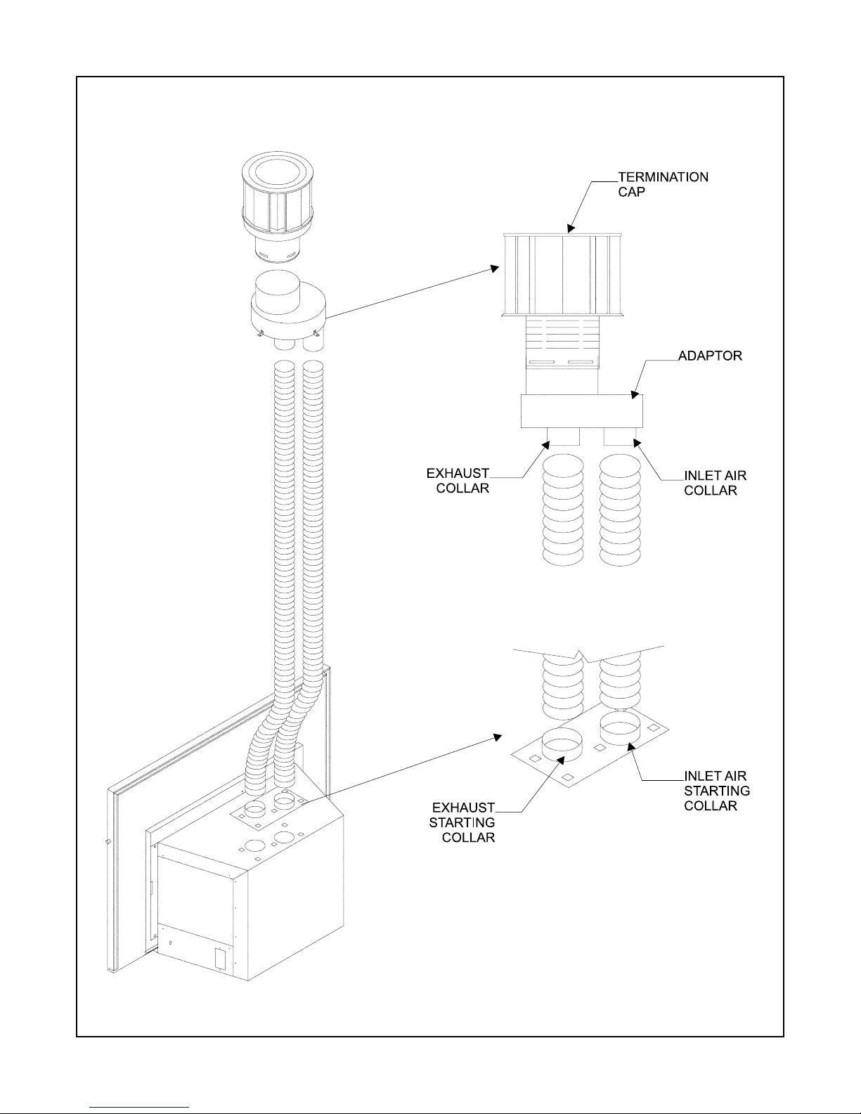
FIGURE 4
FIGURE 5
6

1.1 INTRODUCTION
This model is designed to operate with all combustion
air being siphoned from the outside of the building and
all exhaust gases expelled to the outside of the building. This model is designed to be installed in a masonry fireplace or factory built fireplace. These units
CANNOT be recessed inside combustible construction.
Minimum dimensions of the masonry or factory-built
fireplace into which these models can be installed, are
32 1/8-inches (816mm) width x 13 1/2 -inches (343mm)
depth x 20 1/2 inches (521mm) height.
WARNING: THIS UNIT IS NOT FOR USE WITH SOLID
FUEL.
WARNING: THIS GAS FIREPLACE AND FLUE
ASSEMBLY MUST BE FLUED DIRECTLY TO THE
OUTSIDE AND MUST NEVER BE ATTACHED TO A
CHIMNEY SERVING A SEPARATE SOLID FUEL
BURNING APPLIANCE. EACH GAS APPLIANCE
MUST USE A SEPARATE FLUE SYSTEM.
CAUTION: Prior to connecting the flue system to
the unit, read sections:
1.3 Connecting the Gas Supply
1.4 Accessory Fan
1.2 FLUE SYSTEM
These units MUST use the flue termination described
in the flueing section of the manual.
The control system for these model are a millivolt type.
It consists of a gas control valve/variable regulator, a
standing pilot/thermopile/thermocouple, a piezo ignitor,
and an ON/OFF switch. The controls are located behind the lower grille. Access to the controls is gained
by rotating the grille up. ON/OFF switch is located on
the front surround. See Figure 1.
Minimum inlet gas supply pressure for purpose of input
adjustment is 4.5 inches w.c. (1.13kPa) for natural gas
and 11 inches w.c. (2.75kPa) for propane. Manifold
(outlet) pressures should be set at 3.2 inches w.c.
(.80kPa) for natural gas models and 9.6 inches w.c.
(2.40kPa) for propane models.
In planning the installation for the insert it is necessary
to determine where the unit is to be installed, and
whether optional accessories (wall switch, thermostat,
or remote control) are desired. Gas supply piping
should also be planned. Model ATS-AUST has a factory installed fan.
This model is designed to be installed in a masonry or
factory-built fireplace. The separate 3-inch (76mm) combustion air and exhaust pipes must be run up through
the chimney and terminated vertically. Horizontal flue
terminations MUST NOT be done.
Before starting installation of flue kits, the installer should
read the Gas Fireplace Instructions and the Flue Kit
Instructions to ensure that a proper flue installation is
completed.
Consult your local Building Codes before beginning the
installation.
1.2.1 FLUE SYSTEM APPROVALS
T able 1 and Figures 3-5 show the flue termination caps
and systems approved for use with these models. Approved flue system terminations are labeled for identification. 3-inch (76mm) diameter listed flexible aluminum or stainless steel gas flue is used for both the
incoming combustion air and exhaust flue pipes. NO
OTHER FLUEING SYSTEMS OR COMPONENTS MA Y
BE USED. Detailed installation instructions are included
with each flue termination kit and should be used in
conjunction with this manual.
HORIZONTAL FLUEING
The flue system on this model CANNOT be terminated
horizontally .
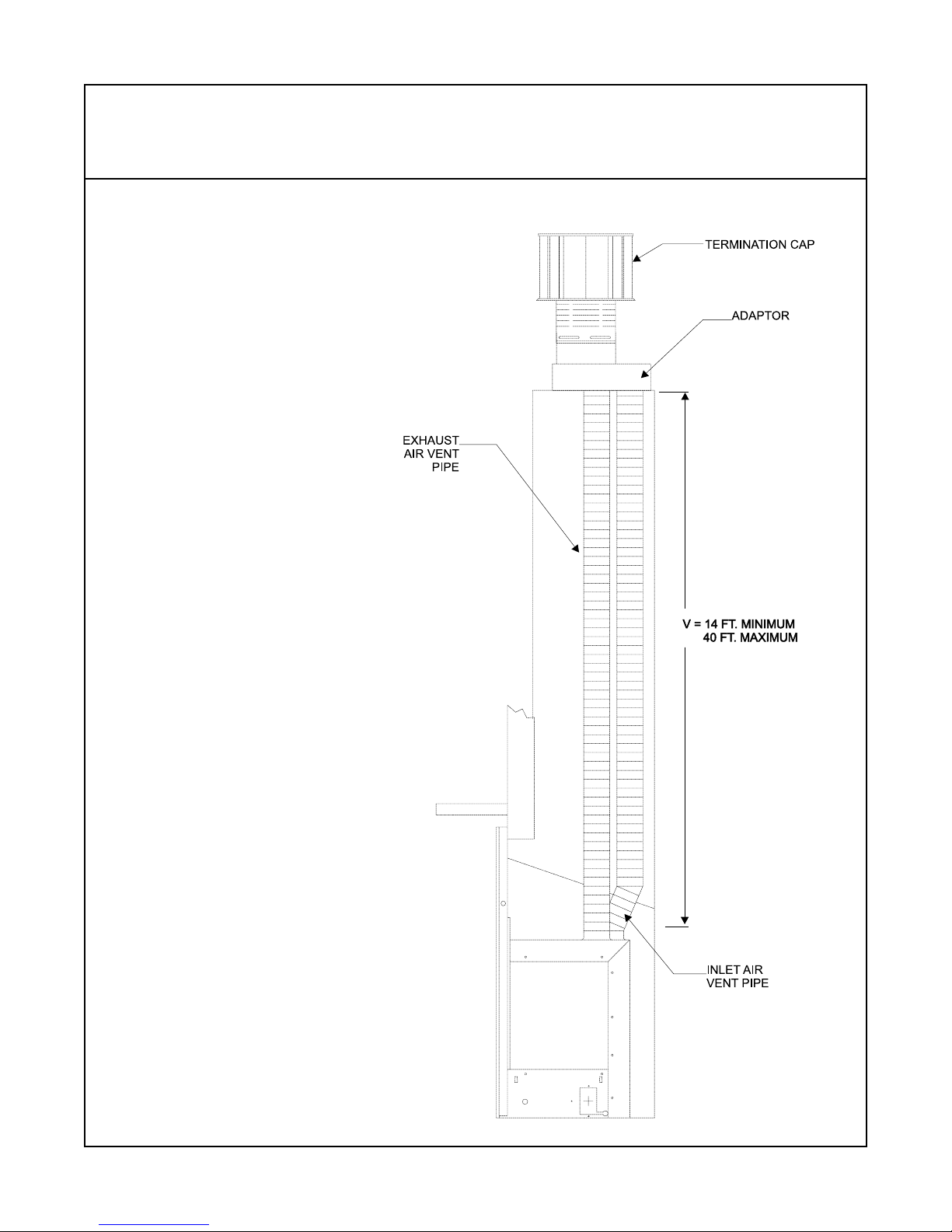
VERTICAL FLUEING
The flue pipes MUST be connected to the proper collars on the unit AND the exhaust flue pipe MUST be
connected to the termination cap or the unit will not
operate. The combustion air flue pipe MUST be connected to the termination cap.
NOTE: The minimum vertical rise (exhaust flue) is
14 feet (3.5M) and the maximum vertical rise is 40 feet
(10M). These dimensions are measured from the starting collars of the unit to the end of the last section of
flue pipe (See dimension V in Figure 3).
A vertical flue termination system installed on this
model will include one (1) length of 3-inch (76mm)
flexible flue pipe for the combustion air, one (1) length
of 3-inch (76mm) flexible flue pipe for the exhaust, one
(1) pipe-to-cap adaptor , and one (1) SLK-991DA V ertical T ermination Kit.
7
 Loading...