

Heat-N-Glo 6000TRS-AU Installation And Operation Instructions Manual
INSTALLATION AND OPERATION INSTRUCTIONS
MODEL: 6000TRS-AU
AUSTRALIAN GAS ASSOCIATION APPROVED
AGA APPROV AL NUMBER 5668
THIS MANUAL MUST BE USED FOR INST ALLATION AND RET AINED
BY HOMEOWNER FOR OPERA TION AND MAINTENANCE.
HEAT-N-GLO, a division of Hearth Technologies Inc.
20802 Kensington Boulevard, Lakeville, MN 55044, USA 1-888-427-3973
This product is covered by one or more of the following patents: (United States) 4,112,913; 4,408,594; 4,422,426; 4,424,792; 4,520,791; 4,793,322;
4,852,548; 4,875,464; 5,000,162; 5,016,609; 5,076,254 5,191,877; 5,218,953; 5,328,356; 5,429,495; 5,452,708; 5,542,407; 5,613,487; (Australia)
543790;586383; (Canada) 1,123,296; 1,297,746; 2,195,264; (Mexico) 97-0457; (New Zealand) 200265; or other U.S. and foreign patents pending.
1
392-900D 10/02
INST ALLA TIONAND OPERA TION INSTRUCTIONS
PLEASE READ THIS MANUAL BEFORE INSTALLING AND
USING THIS APPLIANCE.
MODEL 6000TRS-AU
IS AUSTRAL IA N GA S ASSOCIATION
APPROVED FOR NA TURAL GAS OR PROP ANE
ASA BALANCED FLUE HEATER.
Refer to the appliance data plates for gas consumptions and pressures.
Installation of this appliance should only be carried
out by an authorized person in accordance with the
manufacturers instructions. All relevant codes and
regulations laid down by the gas fitting authorities,
municipal building regulations, electrical wiring regulations, and the requirements of the AGA Gas Instal lation Code must be observed.
This appliance and its components are tested and
safe when installed in accordance with this Installation Manual. Report to your dealer any parts damaged in shipment, specifically check glass condition.
The gas logs and flue system components are in separate packages. Read all instructions before starting
installation and follow these instructions carefully during installation to ensure maximum benefit and safety .
Failure to follow them will void your warranty and may
present a fire hazard.
The Heat-N-Glo warranty will be voided by , and HeatN-Glo disclaims any responsibility for the following
actions:
• Installation of any damaged heater or flue system
component
• Modification of the heater or balanced flue system
installation other than as instructed by Heat-N-Glo.
• Improper positioning of the gas logs or the glass
door
• Installation and/or use of any component part not
manufactured or approved by Heat-N-Glo, not withstanding any independent testing laboratory or
other party approval of such component part or
accessory.
IMPORTANT : Read all instructions carefully before starting installation.
Failure to follow these installation instructions may result in a possible fire
hazard and will void the warranty . Save this manual for future reference.
Copyright 2002 • Printed in U.S.A.
2

TABLE OF CONTENTS
1.0 INSTALLATION INSTRUCTIONS. ...................................................................4
1.1 Locating the Heater .....................................................................................5
1.2 Framing the Heater......................................................................................6
1.3 Flue System Approvals and Installations.......................................................8
1.4 Connecting the Gas Supply..........................................................................16
1.5 Fan .............................................................................................................17
1.6 Mantel Clearances ......................................................................................18
1.7 Log Placement ............................................................................................19
1.8 InstallerTesting............................................................................................21
2.0 OPERATING INSTRUCTIONS. ........................................................................ 21
2.1 Safety and Lighting Information ....................................................................23
2.2 Sa fety Infor mati on........................................................................................23
2.3 Lighting Instructions .....................................................................................24
2.4 Fan Operatio n .............................................................................................25
3.0 SERVICI NG AND MAINTENANCE. .................................................................25
3.1 Remov al of Covers f or Servicing..................................................................26
3.2 Removal of Components for Service............................................................26
3.3 Parts Replacement......................................................................................26
3.4 Adjustments and Replacement Parts ...........................................................26
3.5 Troubleshooting ...........................................................................................27
4.0 REPLACEMENT PARTS. ................................................................................31
Limit ed Warra nty ...............................................................................................33
= Contains updated information.
3

1.0 INSTALLATION INSTRUCTIONS
When planning a heater installation, it’s necessary
to determine:
• Where the unit is to be installed.
• The vent system configuration to be used.
• Gas supply piping.
• Electrical wiring.
• Framing and finishing details.
14-1/4”
(361mm)
9”
(228mm)
• Whether optional accessories—devices such as a
fan, wall switch, or remote control—are desired.
If the heater is to be installed on carpeting or tile, or on
any combustible material other than wood flooring, the
heater should be installed on a metal or wood panel
that extends the full width and depth of the heater.
28-3/8”
(722mm)
21”
(534mm)
27”
(686mm)
(58mm)
2-1/4”
6-3/4”
(173mm)
GAS LINE
ACCESS
38”
(965mm)
36-1/8”
(917mm)
36-1/8”
(917mm)
41”
(1043mm)
TOP
STANDOFFS
GLASS
DOOR
DATA BADGE/LABELS
ELECTRICAL
ACCESS
3-5/8”
(94mm)
8-7/8”
(225mm)
STANDOFFS
GAS LINE
ACCESS
FIGURE 1. Diagram of the 6000 Series
GAS CONTROLS
AND SWITCHES
ELECTRICAL
ACCESS
4
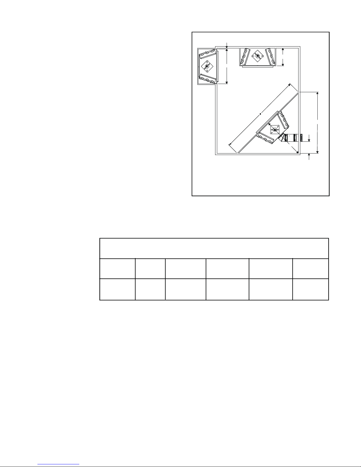
1.1 Locating the Heater
The diagram (See figure 2) shows space and clearance
requirements for locating a heater within a room.
Clearance Requirements
The top, back, and sides of the heater are defined by
stand-offs.
The minimum clearance to a perpendicular wall
extending past the face of the heater is one inch (25
mm).
1”MIN. (25mm)
B
A
D
For 6000 Series Models, the back of the heater may
be recessed 21-1/2 inches (546 mm) into combustible
construction.
Minimum Clearances from the Heater to
Gl as s Back of Sides of Top of
Front Floor Heater Heater Heater Ceiling
36 inches 0 1/2 inch 1/2 inch 3-1/2 inches 31 inches
(914 mm) (13 mm) (13 mm) (89 mm) (787 mm)
AB C D E
42 22 49
(1066mm) (559mm) (1254MM) (1773mm) (2570mm)
FIGURE 2. Heater Dimensions, Locations,
and Space Requirements
11/32 6925/32 9823/32
Combustible Materials
C
20”(508mm)
5
Minimum Clearances from the Flue Pipe to
Combustible Materials
For Vertical
For Horizontal Sections Se ctions At Wall Firestops
Top Bottom Sides Top Bottom Sides
3 inches 1 inch 1 inch 1 inch 2-1/2 inches 1/2 inch 1 inch
(75 mm) (25 mm) (25 mm) (25 mm) (63.7 mm) (13 mm) (25 mm)
For minimum clearances, see the direct vent termination
clearance diagrams on page 7.
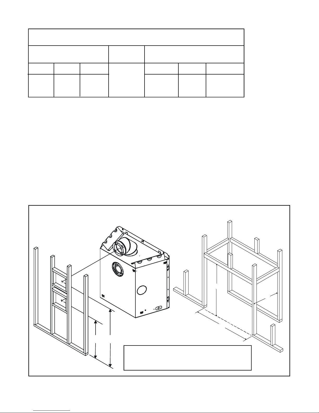
1.2 Framing the Heater
Framing can be built before or after the heater is set in
place. Framing should be positioned to accommodate
wall coverings and heater facing material. The diagram
below shows framing reference dimensions.
CAUTION: MEASURE HEATER DIMENSIONS AND
VERIFY FRAMING METHODS AND WALL COVERING DETAILS, BEFORE FRAMING CONSTRUCTION
BEGINS.
The framing
headers may rest
on the heater
stand-offs.
Framing should be constructed of
2 X 4 lumber or heavier.
B
C
A
E D
A BCD E
42" 38-1/2" 22" 26-7/8" 41 1/2"
(1066mm) (978mm) (559mm) (6837mm) (1054mm)
FI GUR E 3. Framing Dimensions
6
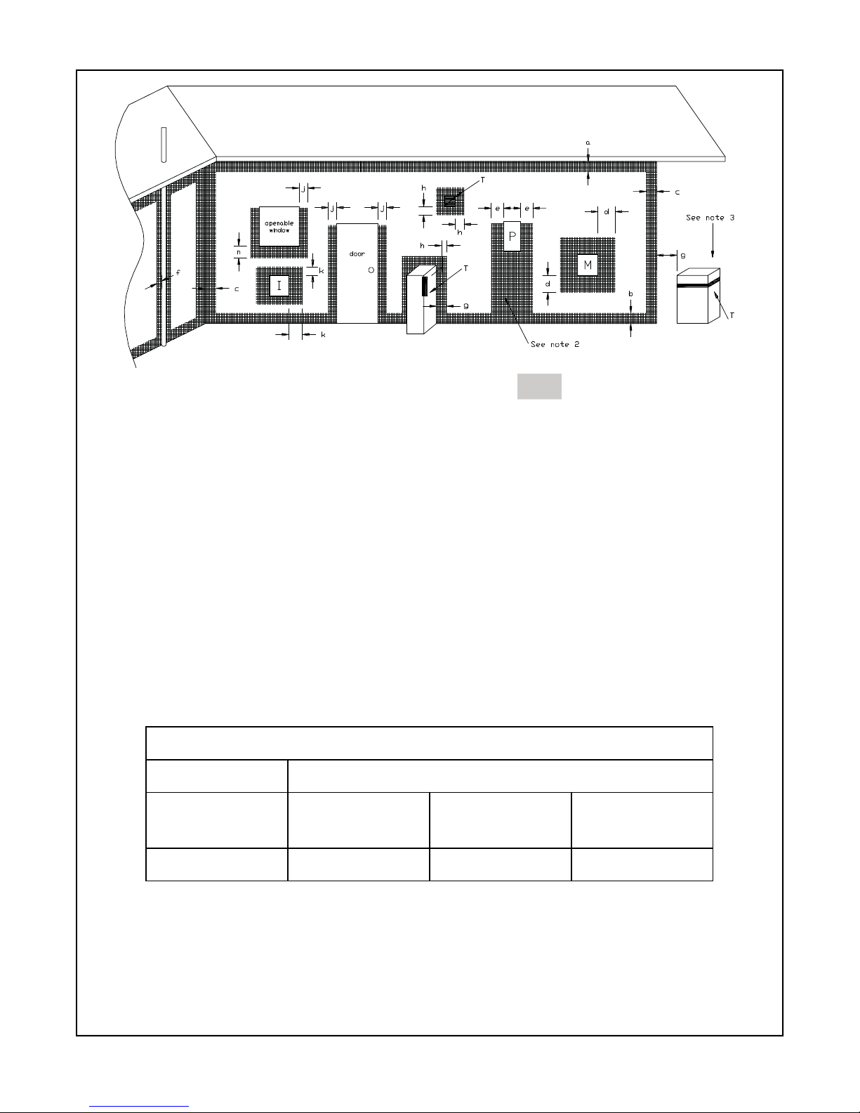
T = Flue terminal M = Gas meter Shading indicates prohibited
I = Mechanical air inlet P = Electricity meter or fuse box areas for flue terminals
a - Below eaves, balconies or other projections: MIN. CLEARANCE (mm)
Appliances up to 50 MJ/h input...........................................................................................300
Appliances over 50 MJ/h input............................................................................................ 500
b - From the ground or above a balcony .....................................................................................300
c - From a ret urn w all o r exte rnal corn er ..................................................................................... 50 0
d - From a gas mete r (M) ........................................................................................................... 1000
e - From an electricity meter or fuse box (P) ............................................................................... 500
f - From a drain or soil pipe ........................................................................................................1 50
g - Horizontally from any building structure (unless appliance approved
for closer installation) or obstruction facing a terminal ......................................................... 500
h - From any other flue terminal, cowl, or combustion air intake ...............................................500
j - Horizontally from an openable window, door, non-mechanical air
inlet, or any other opening into a building, with the exception of
sub-floor ventilation:
Appliances up to 150 MJ/h input.........................................................................................500
Appliances over 150 MJ/h input........................................................................................1500
k - From a mechanical air inlet, including a spa blower .........................................................1500
n - Vertically below an openable window, non-mechanical air
inlet or any other opening into a building, with the exception of ................................. See table
sub-floor ventilation ............................................................................................................ below
CLEARANCES 'n' (mm)
Space heaters All other appliances
Up to 50 MJ/h
input
150 500 1000 1500
NOTES:
FIGURE 4.
1. All distances are measured vertically or horizontally along the wall to a point
in line with the nearest part of the terminal.
2. Prohibited area below electricity meter or fuse box extends to ground level.
3. See clause 5.13.6.6 for restrictions on a flue terminal under a roofed area.
4. See Appendix J, Figure J1(a) and J2(a) for clearances required from a flue
terminal to a LP Gas cylinder. A flue terminal is considered to be a source of ignition.
MINIMUM CLEARANCES REQUIRED FOR BALANCED FLUE TERMINALS
OR THE FLUE TERMINALS OF OUTDOOR APPLIANCES
UP to 50 MJ/h
input
Over 50 MJ/h &
to 150 MJ/h
7
up
Over 150 MJ/h
input
MOD EL FLUE TERMINATION APPROV A LS
6000TRS-AU DVK-01DA, DVK-TVCD
TABLE 1
DVK-01TRD
1.3 FLUE SYSTEM APPROVALS AND
INST A LL ATIONS
This model is approved to use D-Series flue pipe components. A DVK-01DA or DVK-01TRD Termination Cap
must be used to terminate vent systems in a horizontal
position. A DVK-TVCD vertical Termination Cap must be
used to terminate vent systems in a vertical position.
Figures 5 through 14 show the flue systems approved
for use with these models. Approved flue system components are labeled for identification.NO OTHER FLUE
SYSTEMS OR COMPONENTS MAY B E USE D. Detailed
installation instructions are included with each flue termination kit and should be used in conjunction with this
manual.
WARNING: THIS GAS APPLIANCE AND FLUE ASSEMBL Y MUST BE FLUED DIRECTL Y TO THE OUTSIDEAND MUST NEVER BE A TTACHEDTO A CHIMNEY SERVINGA SEP A RA TE SOLID FUEL BURNING
APPLIANCE. EACH GAS APPLIANCE MUST USE A
SEPARATE FLUE SYSTEM-COMMON FLUE SYSTEMS ARE PROHIBITED.
CAUTION: UNDER NO CONDITION SHOULD COMBUSTIBLE MAT ERIAL BE CLOSER THAN 3 INCHES
(2 1/2 INCHES AT WALL FIRESTOPS) FROM THE
TOP OF THE 8 5/8-INCH PIPE OR 1-INCH TO THE
SIDESAND THE BOTTOM FOR HORIZONTAL SECTIONS OF THIS FLUE SYSTEM. VERTICAL SECTIONS
OF THIS SYSTEM REQUIRE A MINIMUM OF 1-INCH
CLEARANCE TO COMBUSTIBLE MATERIALS ALL
AROUND THE 8 5/8 - INCH PIPE.
For alternative installations, other than depicted, contact your dealer for further information.
Refer to Figure 4 for required clearances to flue terminals.
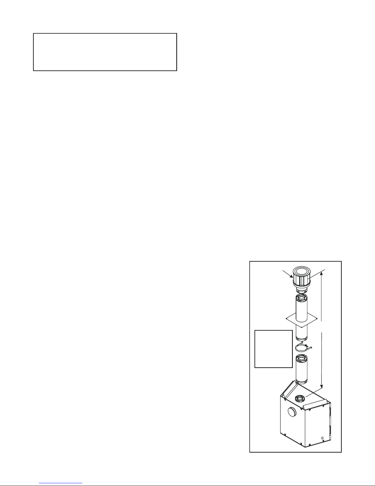
STRAIGHT UP VERTICAL FLUE SYSTEM
Figure 5 shows straight up vertical flue system approved
for use on this model.
Figures 7 through 14 and their corresponding tables
show examples of vent configurations using elbows.
The relationships of vertical rise to horizontal run in
vent configurations using elbows MUST be strictly adhered to.
NOTE: TWO 45-DEGREE ELBOWS MAY BE USED
IN PLACE OF ONE 90 -DEGREE ELBOW.
CAUTION: DO NOT INSTA LL A 45-DEGREE ELBOW
DIRECTLYTO THE HEATER FOR A CORNER INSTALLATION. USE TWO 90-DEGREE ELBOWS.
ONE (1) 90-DEGREE ELBOW
Figures 6 and 7 show an installation using one (1) 90degree elbow . Dimension V is listed asMINIMUM ver-
tical dimensions and dimension H is listed as corresponding MAXIMUM horizontal dimensions.
TWO (2) 90-DEGREE ELBOWS
Figures 9 and 10 show examples of possible installations using two (2) 90-degree elbows. Dimension V is
listed as MINIMUM vertical dimensions, dimension H
is listed as MAXIMUM beginning horizontal dimensions, and dimension H+H
is listed as corresponding
1
TOTAL MAXIMUM horizontal dimensions.
THREE (3) 90-DEGREE ELBOWS
Figures 12 through 14 show examples of possible installations using three (3) 90-degree elbows. Dimensions V are listed MINIMUM first vertical dimensions
and dimensions H are listed as beginning MAXIMUM
horizontal dimensions. Dimensions H+H
1
CAP
andH+H1+H2 are
listed as TOTAL
MAXIMUM horizontal dimensions. Dimensions V+V
listed as TOTAL
MAXIMUM vertical dimensions.
1
are
V
V
MAX. RUN
36 FT .
(10.9m)
STRAIGHT OUT HORIZONTA L FLUE SYSTEM
Figure 6 shows straight out horizontal flue systems approved for use on this model.
ELBOWS
The flue systems installed on this gas heater may also
include one (1), two (2), or three (3) 90 - degree elbow
assemblies.
FIGURE5
8
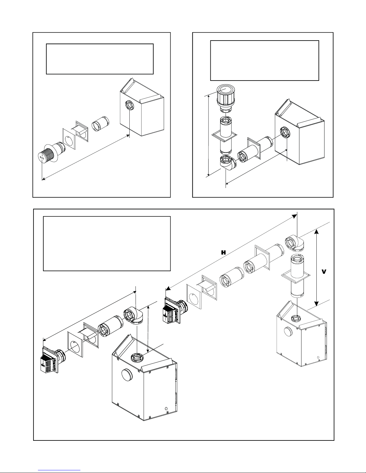
HH
V
MIN. RUN MAX. RUN
13.1" (331mm) 24" (610mm)
H
V H
1´ MIN. (305 mm) 2´ MAX. (610 mm)
2´ MIN. (610 mm) 4´ MAX. (1.22 M)
3´ MIN. (914 mm) 6´ MAX. (1.86 M)
4´ MIN. (1.22 M) 8´ MAX. (2.48 M)
24´ MAX. (7.3 M) 8´ MAX. (2.48 M)
V
H
FIGURE 6. Straight Out Horizontal Flueing
V (FT.) H ( FT.)
1' MIN. (305mm) 4' MAX. (1.22m)
2' MIN. (610mm) 8' MAX. (2.4m)
3' MIN. (914mm) 12' MAX. (3.7m)
4' MIN. (1.22m) 16' MAX. (4.9m)
V+H= 24’ MAX. (7.3m) H = 8' MAX. (2.4m)
H
FI GU RE 7 . Flueing with One 90° Elbow
FI GU RE8. Flueing with One 90° Elbow
NOTE: For corner installations: A 6-inch (152mm)
section of straight pipe may need to be attached to
the fireplace before a 90
o
elbow , to allow the vent
pipe to clear the top standoffs.
NOTE: If a 90o elbow is first attached to the unit,
the maximum horizontal run is 3-feet (914mm).
9

V FT.) H (FT.) H+H1(FT.)
1' MIN. (350mm) 2' MAX. (610mm) 4' MAX. (1.22m)
2' MIN. (610mm) 2' MAX. (610mm) 8' MAX. (2.48m)
3' MIN. (914mm) 4' MAX. (1.22m) 12' MAX. (3.72m)
4' MIN. (1.22m) 6' MAX. (1.8m) 16' MAX. (4.9m)
20' MAX. ( 6.1m) 6' MAX. (1.8m) 16' MAX. (4.9m)
H
1
V
H
FIGURE 9. Flueing with Two 90° Elbows
V FT. H + H1 (FT.)
1' MIN. (30 5m m) 4' MAX. (1.22m)
2' MIN. (6 1 0m m) 8' MAX. (2.4m)
3' MIN. (914m m) 12' MAX. (3.7m)
4' MIN. (1.22m) 16' MAX. (4.9m)
V+H+H
V+V
= 36' MAX.(10.9m)
1
+H= 36' MAX.(10.9m)
1
H+H1 =
16' MAX. (4.9m)
FIG U RE10 . Flueing with Two 90° Elbows
10
 Loading...