

Page 1
He
at
N
et
firmware version
Also read and follow:
3187269
This manual is intended only for use by a qualified heating installer/technician. Read and follow this manual, all
supplements and related instructional information provided with the boiler. Install, start and service the boiler only
in the sequence and methods given in these instructions. Failure to do so can result in severe personal injury,
death or substantial property damage.
Do not use the boiler during construction. Construction dust and particulate, particularly drywall dust, will cause
contamination of the burner, resulting in possible severe personal injury, death or substantial property damage.
The boiler can only be operated with a dust-free air supply. Follow the instruction manual procedures to duct air to
the boiler air intake. If the boiler has been contaminated by operation with contaminated air, follow the instruction
manual guidelines to clean, repair or replace the boiler if necessary.
Affix these instructions near to the boiler. Instruct the building owner to retain the instructions for future use by a
qualified service technician, and to follow all guidelines in the User’s Information Manual.
SHC-IOM-1
Smith
Modulating Hot Water Boilers
Series
®
manual
Control adjustment and operation
instructions for Smith
1.38
This instruction manual applies only to Smith
firmware version 1.38.
Smith Series Hot Water Boiler
Installation and Operating
Instructions
Page 2

TABLE OF CONTENTS
HeatNet Control REV 1.38-1
TABLE OF CONTENTS
TABLE OF CONTENTS .............................................................................................................................. 2
Introduction ................................................................................................................................................ 4
T
HE SMTIH-SERIES HEATNET CONTROL
Features & Specifications ......................................................................................................................... 6
F
EATURES OVERVIEW
........................................................................................................................................................................ 6
Specifications ............................................................................................................................................ 7
Components & Accessories ..................................................................................................................... 8
SETUP & OPERATION ............................................................................................................................... 9
B
ASIC MULTI BOILER SYSTEM OPERATION
M
IXED BOILER TYPES USING PRIORITY SETS
M
IXED BOILER SYSTEM OPERATION
S
TART/STOP PRIORITY CONDITIONS
S
ELECTING MIXED BOILERS
M
IXED SYSTEM EXAMPLES
B
ASE LOADING, RELAY CONTROL
S
ETTING UP BASE LOADING
.............................................................................................................................................................. 13
................................................................................................................................................................ 13
............................................................................................................................................................... 18
.............................................................................................................................................. 4
............................................................................................................................................ 9
..................................................................................................................................... 10
................................................................................................................................................... 10
.................................................................................................................................................. 11
..................................................................................................................................................... 17
Heating Control Methods ........................................................................................................................ 20
H
EATING METHOD
H
EATING METHOD
H
EATING METHOD
H
EATING METHOD
H
EATING METHOD
O
PERATING LIMIT
I
NPUT PRIORITIES
H
EATING METHOD 1
H
EATING METHOD 2
H
EATING METHOD 3
H
EATING METHOD 4 AA INPUT
H
EATING METHOD 5
1 ......................................................................................................................................................................... 20
2 ......................................................................................................................................................................... 20
3 ......................................................................................................................................................................... 20
4 ......................................................................................................................................................................... 20
5 ......................................................................................................................................................................... 20
............................................................................................................................................................................. 20
............................................................................................................................................................................ 20
HEAT DEMAND .............................................................................................................................................. 21
STAGE C
4-20
MODBUS
ONTROL
MA CONTROL
.......................................................................................................................................................... 22
COMMUNICATIONS
T1-T2 ................................................................................................................................... 22
.............................................................................................................................................. 22
.............................................................................................................................. 22
Using The 4-20mA Input (OPTIONAL) .................................................................................................... 23
Circulator Pump Options ........................................................................................................................ 24
Auxiliary Function Options ..................................................................................................................... 25
Outdoor Reset .......................................................................................................................................... 25
Sensors .................................................................................................................................................... 26
Security .................................................................................................................................................... 26
Diagnostics .............................................................................................................................................. 26
Communications ...................................................................................................................................... 26
Page 2
Page 3

TABLE OF CONTENTS HeatNet Control REV 1.38-1
Failsafe Modes ......................................................................................................................................... 26
FAILSAFE REQUIREMENTS: ....................................................................................................................................................... 26
Domestic Hot Water Methods ................................................................................................................. 28
DHW METHOD 1: DHW T
DHW METHOD 1A: DHW H
DHW METHOD 1B: C
DHW METHOD 2: DHW H
DHW METHOD 3: S
DHW METHOD 4: DHW
ANK SENSOR INPUT
EATING
ONLY
OMBO
DHW
AND SPACE HEATING USING A
EADER SENSOR INPUT
PACE HEATING WITH
USING DIRECT CONTROL
................................................................................................................................ 28
USING A SINGLE BOILER OR A
............................................................................................................................. 30
DHW O
VERRIDE
............................................................................................................................ 31
............................................................................................................... 30
DHW MASTER
MASTER B
AND MEMBER BOILER(S) EMPLOYING
OILER AND MEMBER BOILER(S) EMPLOYING
H-NET ... 28
H-NET ............. 29
Stack Temperature Monitoring ............................................................................................................... 31
Wiring Connections ................................................................................................................................. 33
Calibration ................................................................................................................................................ 44
Log Entry .................................................................................................................................................. 45
Default Settings & Menu Item Descriptions — SETUP .......................................................................... 46
Default Settings & Menu Item Descriptions — ADVANCED SETUP ..................................................... 50
MODBUS Communications ..................................................................................................................... 54
Troubleshooting ...................................................................................................................................... 61
Smith HeatNet Control Run Screen ........................................................................................................ 65
* Status Information ................................................................................................................................... 3
S
TATUS INFORMATION SCREENS
.......................................................................................................................................................... 3
Smith HeatNet Control Menu Tree — Smith Version 1.38 ..................................................................... 68
Smith HeatNet Control Advanced Menu Tree — Smith Version 1.38
........................................................ 69
Worksheet ................................................................................................................................................ 70
Thermistor Resistance/Temperature Table ............................................................................................ 73
Status Screen Fault Display .................................................................................................................... 75
Line 4 Log Entries: .................................................................................................................................. 78
Information contained in this publication regarding device applications and the like
is provided only for your convenience and may be superseded by updates. It is
your responsibility to ensure that your application meets with your specifications.
SMITH MAKES NO REPRESENTATIONS OR WARRANTIES OF ANY KIND
WHETHER EXPRESS OR IMPLIED, WRITTEN OR ORAL, STATUTORY OR
OTHERWISE, RELATED TO THE INFORMATION, INCLUDING BUT NOT
LIMITED TO ITS CONDITION, QUALITY, PERFORMANCE,
MERCHANTABILITY OR FITNESS FOR PURPOSE.
http://www.smithboiler.com/
Page 3
The Smith name and logo, Hydrotherm name and logo, Mestek name and
logo, HeatNet, and H-Net name and logo are registered trademarks of
Mestek, Incorporated in the U.S.A. and other countries.
BACnet is a registered trademark of ASHRAE. LonWorks is a registered
trademark of Echelon Corporation. All trademarks mentioned herein are
property of their respective companies.
© 2010, Mestek Technology Incorporated, Printed in the U.S.A., All
Rights Reserved.
Page 4

FEATURES & SPECIFICATIONS HeatNet Control REV 1.38-1
Introduction
The S
MITH
HeatNet Control
The Smith HeatNet boiler control is designed to provide the
Smith Water boilers with an integrated boiler management
system on every boiler. Steam Boiler control is not currently
available. The Smith HeatNet control provides for optimized
heating efficiency without the need for a “wall mount
control”. Since the Smith modular control method is based
on digital communications (Heat-Net), analog control
signals are not required. Although the use of analog control
signals is still supported (4-20mA control loops and 0-10vdc
(20mA minimum) control voltages), a higher level of
control precision, repeatability, and feedback is gained with
digital communications control.
With the HeatNet control, optimized heating efficiency is
accomplished by setting the Modulation Maximum (ModMax) setting to exploit the inverse efficiency curve. This
value can be adjusted so that as each boiler is added, it
operates at its maximum turndown. This allows the
maximum number of boilers to operate at their lowest
inputs, until all boilers are firing. Once all boilers are firing,
full range modulation control is allowed. An outdoor reset
function is also provided to assist in the optimized heating
efficiency of the Smith boilers.
The Smith boiler with the HeatNet control, can be operated
in multiple ways:
A. As a stand-alone boiler.
B. A boiler in a Boiler Network using the HeatNet (H-
Net ™) protocol.
C. A member boiler controlled by a boiler management
system with multiple input control methods.
The primary purpose of the control is to maintain the boiler
water temperature at the supply or the header sensor using a
target setpoint. While performing this task, the control also
monitors dedicated external limits in a limit string and
provides an orderly shutdown and fault indication in the
event of a tripped limit. The monitored limits include a
HIGH LIMIT AQUASTAT, LOW WATER CUTOFF, GAS
PRESSURE, FLOW, IGNITION CONTROL fault, GAS
VALVE alarm, VARIABLE FREQUENCY DRIVE alarm,
and other optional or user selectable limits.
The HIGH LIMIT circuit is independent of the
control and shuts down the ignition control and
the boiler if the control board or other
component of the boiler was to malfunction.
The control will continue to function and report
the fault, but its ability to control the boiler will
end.
Each Smith boiler employing this control can function as
either a master or a member. This allows one boiler (Master)
to be in control of target temperature. The other boilers
(Members) only respond to the commands issued by the
Master. If using an external control, all boilers can be setup
as members. The following will define the roles of master
and member.
Master
A boiler becomes a master when a temperature sensor is
connected to the J10 “SYS/DHW HEADER” terminals. The
sensor is auto-detected.
The master senses and controls the common system
header/loop water temperature using a system setpoint. It uses
any boilers it finds (over the H-Net communications cable) to
accomplish this. It can also monitor the Outside Air (OA)
temperature to provide outdoor reset functionality. Only one
master is allowed in a system.
When operating as a master, the boiler provides a control
method using a PID algorithm to regulate water temperature.
This algorithm allows a single boiler (Master), or multiple
(Master + Member) boilers.
Figure 1
The control algorithm is based upon a Heat Band, at the
center of which is the setpoint. While below the Heat Band,
boilers are staged on and modulated up until the Heat Band
is entered. Once in the Heat Band, modulation is used to
maintain setpoint. Boilers are shut down only when the top
of the Heat Band is breached. Timers are also used to
prevent short cycling.
While staging the boilers on, a modulation clamp
ADVANCED SETUP:MOD MAX – LAST FIRE is used
to hold the boilers at a lower fire rate until the last boiler is
fired. Once the last boiler fires the modulation clamp is
removed and all boilers are allowed to fire above this
clamped percentage to 100%. This “boiler efficiency” clamp
is defaulted to 70% and thus limits all of the boilers
individual outputs to 70% until the last boiler fires. All
running boilers modulate up and down together, always at
the same modulation rate. As a general rule, this percentage
should be no lower than twice the minimum turndown to
minimize short cycling.
the system, the Master boiler employs an ADAPTIVE
MODULATION algorithm to prevent over firing of the
system. The Master communicates over the H-Net to view
Heat band
BOILERS
UPPER HEAT
BAND LIMIT
SETPOINT
LOWER HEAT
BAND LIMIT
WATER
TEMPERATURE
STAGED
OFF
Boilers Staged
ON
Time
When additional boilers are needed to achieve setpoint in
Page 4
Page 5

FEATURES & SPECIFICATIONS HeatNet Control REV 1.38-1
the exact status of each Member boiler. When a new boiler
is added, the Master boiler adjusts the system modulation
rate lower to compensate for the BTUs that will be
introduced by the newly added boiler. This adjustment
occurs when the newly added Member boiler enters its ON
CALL state (default setting). This can be changed to PILOT
when the new boiler is called using the menu: ADVANCED
SETUP:ADAPTIVE MOD:DROP DOWN. Once the
Main Valve (on the newly added boiler) is opened, and the
DELAY RELEASE timer equals zero, the PID algorithm is
allowed to control the system modulation. Setting the
DELAY RELEASE timer will allow some “soak” time of
the newly added boiler before releasing modulation control
to the PID.
The ADAPTIVE MOD menus are disabled on a
Member boiler, but are still visible.
Member
If a “SYS/DHW HEADER” sensor is not connected to J10, a
boiler always defaults to the role of Member.
The Member boiler can operate as part of a multi-boiler
system or as a stand-alone unit.
In a multi-boiler system the Member typically receives its
command signals from a designated Master-boiler. It is also
capable of receiving inputs from an external control system.
The boiler responds to these signals, to start/stop the burner,
and/or to modulate the firing rate. The outlet water
temperature is also monitored. If the outlet temperature
approaches the operating limit temperature setpoint
(adjustable), the boilers firing rate is limited and its
modulation value is reduced to minimize short-cycling. If the
operating limit is exceeded, or if an interlock trips, the boiler
is shut down. When connected with a network cable, in a
Master/Member role, the Members' status is interrogated by
the Master boiler.
In a stand-alone installation the Member typically receives its
command signals internally and operates based upon the outlet
water temperature input and the established settings in the
menu (Local Set-point) to start/stop the burner, and/or to
modulate the firing rate. If the operating limit is exceeded, or
if an interlock trips, the boiler is shut down. As in a multiboiler system, a stand-alone Member boiler is also capable of
receiving inputs from an external control system.
When using the H-Net network cable in a Master/Member
system, the system setpoint is sent from the Master as a digital
signal, along with the modulation value to control firing rate.
It also receives its command to start or stop over the H-Net
cable. Also, the SYSTEM CLOCK only needs to be set on the
MASTER. The Master will then set the time on all member
boilers.
If not using the H-Net protocol (cable), an external control can
send a 4-20ma signal along with a 4-20ma enable signal to
control the firing rate or setpoint. The boiler may also be
treated as a 2-stage boiler or an ON-OFF boiler using the
dedicated T-inputs.
Page 5
Page 6

FEATURES & SPECIFICATIONS HeatNet Control REV 1.38-1
Features & Specifications
1. Five levels of external control inputs, including
modulation and staging that provide application
flexibility.
2. Digital Communications Control (analog 4-20ma and 0-
10vdc control supported, but not required).
a. Boiler to Boiler : HeatNet (H-Net)
b. Building Management System (MODBUS,
Optional BACnet or LonWorks) to Boiler
3. Distributed control using the HeatNet (H-Net) protocol
for up to 16 boilers. Eliminates the need for “wall
mounted” controls.
4. Analog Control 4-20ma and 0-10vdc (20mA minimum
current) signals supported.
5. System/Boiler operating status text display
6. Interlock, Event, and System logging with a time
stamp.
7. Advanced PID algorithm optimized for the Smith-
Series boilers.
8. (5) Dedicated temperature sensor inputs for: Outside
Air Temperature, Supply (Boiler Outlet) Temperature,
Return (Boiler Inlet) Temperature, Header (Common
System Supply) Temperature, and a Stack sensor for
monitoring stack temperature conditions
9. Automatically detects the optional temperature sensors
on power up.
10. Menu driven calibration and setup menus with a bright
(Adj.) 4 line Vacuum Fluorescent Display.
11. (8) Dedicated 120vac interlock monitors (selectable),
and 8 dedicated 120vac system monitors used for
diagnostics and providing feedback of faults and system
status.
12. Multiple circulator pump control modes.
13. Combustion Air Damper control with proof time,
support for a common combustion air damper.
14. USB/RS485 network plug-in to allow firmware updates
or custom configurations.
15. Optional BACnet or LonWorks interface.
16. Alarm Relay dry contacts, and Audible Alarm.
17. Runtime hours, and Cycles(based on Main Valve
Open).
18. Outdoor Air Reset with programmable setpoint and
ratio.
19. Time of Day clock to provide up to (4) night setback
temperatures.
20. Failsafe mode when a Building Management System is
controlling setpoint. If communications is lost, the
boiler/system automatically transfers to local boiler
setpoint control.
21. Rotation Methods(Lead-Lag): True Rotation (based on
boiler runtime)is default. First On First Off (FOFO),
and Last On First Off (LOFO) is an optional
programmable setting.
22. Programmable password protection to secure the
programmable settings.
23. Heat exchanger delta T limiting feature. If the
temperature across the heat exchanger is greater than
40F, a menu selection can set to one of (2) modes. (1.)
The input rate is reduced to half of the called for rate.
(2.) The boiler will shut down, but when the Delta
temperature across the heat exchanger drops by 10 °F
the boiler will restart.
24. Low inlet temperature warning if return water
temperature drops below 130°F.
25. Remote 4-20mA setpoint control using a mapped
setpoint range to the 4-20mA control signal.
26. Freeze Protection allowing automatic starting of
boiler(s) using (2) Failsafe modes.
27. Adaptive Modulation. When additional boilers are
called, the Master adjusts all boilers fire rates to
compensate.
28. Mixed boiler types in a system.
29. Support for Domestic Hot Water (DHW) using a 10k
Sensor or a dry contact input from a tank thermostat.
30. Domestic Hot Water relay for use with a pump or
valve.
31. On-board power and socket for Protocessor
BACnet/LonWorks module.
32. HI/LO relay control option from connector J4
33. Stack temperature Warning at 550F and the fire rate
limited to ½ rate at 700F
34. Base Loading of (1) boiler.
Page 6
Page 7

FEATURES & SPECIFICATIONS HeatNet Control REV 1.38-1
Specifications
Control Microprocessor based PID modulating control (NOT a safety limit )
Environment -40 F to 140 F, <90% RH non-condensing
Input Power 24 VAC, 500 ma
Relays System Pump, Damper, Circulator, Alarm, DHW Pump 8A 250 VAC resistive
K8 on J4.1 &.2 for Base Loading and Dual Fuel 1/4 Amp
AC Interlocks 24 VAC – 120 VAC input
Control Inputs AA, Heat Demand, 4-20ma Enable, OA override, T1-T2 (dry contact inputs)
4-20mA, 0-10 VDC (20mA source current)
Dimensions Board: 9” wide: 6” high : 2” deep, Enclosure: 11 ¾” wide: 10” high : 5” deep
Temperature Sensors NTC thermistor, 10K @ 77 F, ,+/- 1 F; 1k PT RTD
USB 1.0
RS485 MODBUS Modbus RTU
Boiler-to-Boiler HeatNet (H-Net)
Network Optional LonWorks, BACnet available bridge to MODBUS port
Page 7
Page 8

FEATURES & SPECIFICATIONS HeatNet Control REV 1.38-1
Components & Accessories
Part Number Component
Smith-Series Control Board
02-4278 Graphics Display Board
02-3926 Temperature probe (bullet type, 1x.250 inch) ACI/10K-CP-BP
02-4283 Supply, Header, Return Sensors ACI 10k-CP-I-NW
02-4285 Sensor with well ACI CP-I-2.5”
02-4286 Sensor with well ACI CP-I-4”
02-4281 Strap-on sensor ACI 10k-CP-S
02-4280 Outside Air Sensor with Housing ACI 10k-CP-O
Installation & Operation Manual
40-5409 RJ45 Communications Cable Assembly, 25 feet
40-5411 Ribbon Cable Assembly (Display Control)
58-1833 10k ohm Calibration Resistor
40-5408 USB Cable Assembly, 6ft
60-5631 Terminal Block Screwdriver
Contact Factory MODBUS to BACnet bridge
Contact Factory MODBUS to LonWorks bridge
Page 8
Page 9

SETUP & OPERATION HeatNet Control REV 1.38-1
Master
Members
SETUP & OPERATION
Basic Multi Boiler System Operation
For boiler system setup/installations please
refer to Refer to the 2008 ASHRAE
Handbook, CH12 or later revision.
A basic multi boiler system typically uses boilers of the
same size and type. With HeatNet, this includes (1) Master
and (1-15) Member boilers. The boilers are connected
together using an H-Net communications cable effectively
creating (1) boiler. This allows the system heating BTUs to
be distributed amongst all of the boilers. (See: Error!
Reference source not found., Error! Reference source
not found., page Error! Bookmark not defined.). Error!
Reference source not found., Error! Reference source
not found., page Error! Bookmark not defined.).
Figure 2
A basic multi boiler system can be configured using the
boiler menus to create custom systems/features. These
features are best described in the section: Default Settings
& Menu Item Description, page 46. Along with these
menu items are hardware support for many
auxiliary functions.
Once the system has been properly setup (all default menu
values used and HeatNet addresses assigned), the system is
enabled by placing the REMOTE/LOCAL switch to the
LOCAL position on the Master boiler. All Member boilers
must have their respective switches in the REMOTE
position. Once the Master boiler’s Heat Demand input
(LOCAL switch) closes, the system is operational and will
fire as many boilers as it needs to maintain the header water
temperature’s setpoint.
When a boiler is to be fired in a multi boiler system (header
water temperature is below the heating band), the Master
checks the HeatNet boilers it has available. Then the Master
checks if a Lead Boiler is to be used (LEAD BOILER > 0).
The Master boiler then looks at which type of firing rotation
it has selected: LOFO, FOFO, TRUE (runtime), or MIXED.
In our example we will use the TRUE (runtime) rotation
since it is the default.
Basic multiple boiler system
1 to 15 boilers total
The Master now checks all of the runtimes to determine
which boiler has the least runtime based on the MIN
RUNTIME setting in ADVANCED SETUP:FIRING
MODE:. The MIN RUNTIME setting is the minimum
runtime interval in hours that is used to compare boiler to
boiler runtimes.
Once the boiler to fire has been determined, the Master
sends the command over the H-Net cable to fire that boiler
and resets the ADD BOILER delay timer to prepare for the
next boiler to fire. If the header water temperature is still
below the heating band and the ADD BOILER delay timer
has counted down to 0, the process is repeated until the
header water temperature enters the heating band.
When a boiler receives a command to fire it:
1. Enables the System Pump Relay and waits for the
System Flow Prove switch to make in the interlock
string (J5B.1).
2. Next, the interlock string is checked for any other
tripped interlocks (J5A & J5B). Also, the High Limit,
Ignition Control, Gas Valve Prove (Optional), and any
hardware faults (sensors, etc…) are checked before
continuing.
3. If all interlocks are good, and if the combustion air
damper is used, the K5 combustion air damper relay is
enabled. The damper prove switch is then monitored for
closure.
4. The local pump relay K6 is now energized and the
proof of flow is monitored for closure on J5B.7.
5. With all interlocks good, the boiler start relay K1
energizes and provides a signal to terminal 6 of the
ignition control.
6. The ignition control then begins an ignition cycle by
first energizing its blower relay. The H-Net control then
sets the blower VFD to the Pre-purge speed.
7. The ignition control then waits for the air switch to
close by monitoring its terminal 7.
8. Once the pre-purge time expires on the ignition control,
it closes its pilot valve relay causing the H-Net control
to adjust the blower to the ignition speed and attempt to
light the pilot.
9. If the pilot is successful, the ignition control energizes
its main gas valve relay and starts its trial for main
flame (UV scanner).
10. Once the main flame is proven, the H-Net control holds
the fire rate at low fire for the MODULATION
DELAY time period. After this time expires, the PID
modulation is then allowed to modulate the boiler and
places the boiler in the running state.
Page 9
Page 10

SETUP & OPERATION HeatNet Control REV 1.38-1
As boilers are added to the system the ADVANCED
SETUP:ADAPTIVE MOD:DROP DOWN menu
determines when the modulation rate drops down to
compensate for the newly added BTUs. For the drop
down to be active one boiler needs to be running when a
new boiler is added (see: Introduction: Smith HeatNet
Control: Master).
If all boilers are firing, the modulation rate is allowed to
go to 100%. If all boilers are not firing, the modulation is
limited to the MOD-MAX clamp value. The MODMAX clamp is used to keep the boilers running as
efficiently as possible. The following Mixed Boiler
System Operation: Selecting Mixed Boilers section
outlines this with examples.
Once the header water temperature is in the band, only
the modulation rate is used to achieve the target setpoint.
The system will then maintain setpoint until the load
demand increases or decreases.
As the load decreases, the header water temperature will
start approaching the top of the band. The PID now
lowers the modulation rate to the boilers while trying to
keep the temperature within the heating band. If the
system is now delivering too many heating BTUs, the
water temperature will cross the top of the heating band.
When the header water temperature first exits the top of
the heating band, the runtimes of the boilers are again
checked for the one with the most runtime. The selected
boiler will then turn off immediately and a shed boiler
delay timer will be loaded with the SHED BOILER
delay time. This time will need to expire before the next
boiler will stop, but only if the header water temperature
remains above the heating band. This timer is used to
allow the header water temperature to settle back into the
band when a boiler is stopped. When a boiler is stopped
there is a fixed rate of BTUs (Min Fire) that will be
removed (PID discontinuity to modulate from Min Fire
to 0 BTUs on a boiler). The timer allows for this
immediate large discontinuous loss of BTUs.
This cycle will continue until the call for heat is removed
or the Warm Weather Shutdown feature is enabled.
Mixed Boiler Types Using
Priority Sets
Using the Basic Multi Boiler System Operation, a MIXED
boiler priority method may be added to control condensing,
non-condensing, base load, or other boiler SETs in a system
together. These sets compose a system which provides for
optimal performance and economy.
A boiler set can be constructed by simply setting the firing
priority on each boiler (to be in a set) at the same priority.
Setting all (example) condensing boilers to the highest
priority of 1, and then setting all (example) non-condensing
boilers to a priority of 2, will create (2) sets of boilers, one
condensing and the other non-condensing. Once this is
done, the priority 1 set of condensing boilers will have a
firing order that has a higher priority and is independent of
the other non-condensing set with the lower priority. The
boiler set with the highest priority can then be fired based on
a conditional settings menu. The lower priority set will
follow.
Mixed Boiler System Operation
Starting Boilers:
When a boiler is to be fired (water temp is below the heating
band), the Master checks the HeatNet boilers it has
available. The Master boiler then looks at which boilers are
returning priority firing status (set on a boiler in:
(ADVANCED SETUP:SYSTEM:BOILER
TYPE:PRIORITY : 1). If the Start condition for the Priority
1set is met (ADVANCED SETUP:FIRING MODE:
MODE: MIXED:SET FIRST (example), the Master or
Member boiler that is configured as PRIORITY 1, with the
lowest runtime, will be fired FIRST (example).
As long as the start condition for Priority 1 is met, all
boilers in the PRIORITY 1 set will fire based on runtime.
Once all boilers in the PRIORITY 1 set have fired, the
PRIORITY 2 set of boilers will fire based on runtime.
If the Start condition changes and/or is not met (such as
with: OA T or RET temp), the PRIORITY 2 set of boilers
will fire first/next based on runtime. This has the effect of
flipping the priority of the sets.
Stopping Boilers:
When a boiler is to be stopped (water temp is above the
heating band), the Master checks the HeatNet boilers it has
available. The Master boiler then looks at which boilers are
returning priority firing status (set on a boiler in:
(ADVANCED SETUP:FIRING MODE: MODE:
MIXED:SET LAST(example) If the Stop condition for
Priority 1 is met, the Master or Member boiler that is
configured as PRIORITY 1 with the highest runtime will be
stopped LAST (example). As long as the stop condition and
SHED DELAY time are met, all remaining PRIORITY 1 set
of boilers will stop based on runtime. If the Stop condition
changes and/or is not met (such as with: OA T or RET
temp), the PRIORITY 2 set of boilers will stop first/next
based on their highest runtime.
A boiler’s firing priority can be designated as such in:
“ADVANCED SETUP:SYSTEM:BOILER TYPE:FIRING
PRIORITY : 1” menu on each boiler. A priority of ‘1’ is the
highest priority, a ‘2 the lowest (default is always 2).
Page 10
Page 11
OPTIONAL FEATURES HeatNet Control REV 1.38-1
S E T : O A T < 1 5 ° F
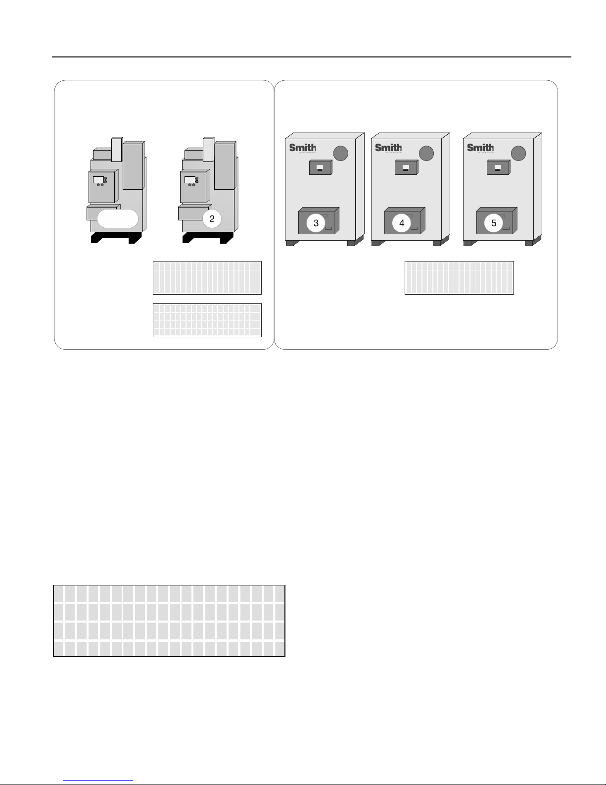
Figure 3
FIRING MODE menu
(master boiler only)
BOILER TYPE menu
(all boilers in set)
Mixed Boilers: Example: Condensing/Non-Condensing
Master
PRIORITY 1
Condensing (Set)
>MODE MIXE D
MIN R UN TI ME: 10HR s
MIN O FF TIME: 0s
PREDICT S TART: YES
>FIRING PR IORITY :1
BTU I N 2000,000
CONDENSING YES
MASS MEDIUM
Non-Condensing (Set)
BOILER TYPE menu
(all boilers in set)
PRIORITY 2
>FIRING PR IORITY :2
BTU I N 2000,000
CONDENSING NO
OIL D IR EC T FIR E X XX
In the example Mixed Boilers: Condensing/NonCondensing., condensing boilers and non-condensing
boilers are used, but other combinations may also be used.
Another example could use (2) small boilers and set them to
Priority 1 and then use (3) larger boilers and set them to
Priority 2. Using these priority settings (with the conditions
menu), the small boilers can run first during the shoulder
months (Spring and Fall) and the larger boilers can fire last
during the colder Winter season (base loading set).
Before the MIXED method can be used, the firing mode on
the Master boiler must be set to MIXED. ADVANCED
SETUP:FIRING MODE: MODE: MIXED. Pressing the
SELECT key when the cursor is pointing to MIXED will
enter the conditions menu. The START and STOP
conditions for starting and stopping the priority boiler set
may be configured here. Temperatures are adjustable.
S T A R T P R I O R I T Y 1
> S E T : F I R S T
S T O P P R I O R I T Y 1
Start/Stop Priority Conditions
The following is an example using mixed
condensing and non condensing boilers:
FIRE FIRST
Condensing boilers may be configured to fire first (set to
PRIORITY 1) when:
1. The Return water temperature is below 140F and
condensing occurs. (The Master’s return water sensor
would need to be moved to the header return.)
2. The Outside Air Temperature is above a setpoint
determined by the system configuration. This setpoint
ensures that the more efficient condensing boilers run
first during shoulder months (Spring and Fall) when
minimal heating is required. Below this setpoint, larger
boilers should be brought on first to “base load” the
system.
3. Greater efficiency is required.
Once the conditions menu has been entered, the firing order
and stop order of the priority 1 boiler set can be selected
based on up to (3) conditions in the conditional settings
menu. All conditional settings apply to the priority 1 boiler
set. When the conditional settings do not apply to the
priority 1 set, the conditional settings will apply to the
priority 2 boiler set.
Page 11
STOP FIRST
Condensing boilers may be configured to stop first (set to
PRIORITY 1) when:
1. The Return water temperature is above 140F and
condensing is minimized, thus leaving the larger lower
cost boilers running to carry the load.
Page 12

SETUP & OPERATION HeatNet Control REV 1.38-1
S E T :
L A S T
2. The Outside Air Temperature is below an adjustable
setpoint determined by the system configuration. This
setpoint ensures that the larger non-condensing boilers
run during the coldest months when maximum heating
is required. Above this setpoint smaller condensing
boilers should be brought on first to run the system as
efficiently as possible.
3. Maximum heating is required
START PRIORITY 1 SET SELECTIONS
(Always the lowest runtime first):
The condensing boiler set (Priority 1) has a
higher Priority to fire when one of these
conditions is met. Values are adjustable.
FIRST: The condensing boilers (Priority 1) are always
started FIRST
OA T > 15F: The condensing boilers (Priority 1) are
started when the OA temperature is greater than the Mixed
Boiler Outdoor Air Temperature setting.
RET < 140F: The condensing boilers (Priority 1) are
started when the Return water temperature is less than the
Mixed Boiler Return temperature setting (This may not
applicable in most configurations since the local return
temperature on the Master is used to provide a difference
temperature across the heat exchanger. However, the return
temperature sensor may be moved on the Master to provide
system return temp if the difference temp is not required).
STOP PRIORITY 1 SET SELECTIONS
(Always the highest runtime first):
The condensing boiler set (Priority 1) has a
higher Priority to stop when one of these
conditions are met. Values are adjustable.
LAST: The condensing boilers (Priority 1) are always
stopped LAST.
OA T < 15F: The condensing boilers (Priority 1) are
stopped first when the OA temperature is less than Mixed
Boiler Outdoor Air Temperature.
RET > 140F: The condensing boilers (Priority 1) are
stopped first when the Return water temperature is greater
than the Mixed Boiler Return temperature. (This may not
applicable in most configurations since the local return
temperature on the Master is used to provide a difference
temperature across the heat exchanger. However, the return
temperature sensor may be moved on the Master to provide
system return temp if the difference temp is not required)
Start/Stop settings
Any combination of Start Conditions and Stop Conditions
can be used to optimize the mixing of condensing (Priority
1) and non-condensing boilers (Priority 2) for best
performance/economy.
The default settings for the start and stop conditions of the
condensing set are:
S T A R T P R I O R I T Y 1
> S E T : F I R S T
S T O P P R I O R I T Y 1
The default start setting always starts the condensing boilers
(Priority 1 example) first, except for the lead boiler setting.
The lead boiler will always start first if enabled, unless
there is a boiler already running (this includes a Member
boiler in LOCAL). The default stop condition setting always
stops the condensing boilers (Priority 1) last.
If prolonging the life of the heat exchanger(s) on noncondensing boilers is very important, consider starting the
condensing boilers (KN series) when the return water
temperature is below 140F.
The return water temperature sensor would
need to be moved from the Master’s return
inlet to the system return. The EXCHGR
DELTA may need to be adjusted in
SETUP:AUX FUNCTIONS:HEAT
EXCHANGER to prevent the Master from
going to ½ input when a high DELTA T is
reached.
This method would lead to the non-condensing boilers
carrying the load when the system temperature
stabilizes above 140F, since non-condensing boilers
will start first with the Return water temperature is >
140F. The condensing boilers can then be stopped first
when the RET water temperature is above the 140F.
Remember, any combination of the Start and Stop
conditions may be applied for best performance and
economy in the system.
Base load boilers can also be mixed in the same way as
condensing and non-condensing boilers. The base load
boiler(s) can be prioritized in one set (example, Priority
2) and non-base load boilers (Priority 1). The non-base
load boilers can then be set to fire first and once they
are all firing, the base load boiler would fire.
To minimize the cycling of a large base load boiler,
consider using the stop condition. Change it to the OA
T < 15F (Outside Air Temperature) condition. This
setting may be used to stop the priority 1 boiler set
when the OA T drops below the OA T setpoint, thus
leaving the large base loaded boiler on and shutting off
Page 12
Page 13

SETUP & OPERATION HeatNet Control REV 1.38-1
System
Effective
MOD
MOD
the condensing boilers first. This is also true when
using the OA T setting to start the priority 1 boiler set
when the OA T is above the start setpoint. To use
temperatures as start and stop conditions, the system
design temperatures must be known.
Selecting Mixed Boilers
There are a few factors to consider when choosing which
type of boilers to use in a mixed system. These factors
need to be considered when boilers are added or shed.
When BTUs are introduced into the system by adding
boilers, the amount of introduced BTUs should be
smooth (linear). If these factors are not considered,
discontinuity in BTUs may occur when boilers are added
and as a result, short cycling will occur.
1. Turndown: This is the ratio of minimum fire rate
to maximum fire rate: Example: a 20% minimum
modulation = 5:1 turndown (100%mod / 20% mod).
A (1) million BTU boiler = 200,000 BTUs
minimum input.
2. MOD MAX CLAMP: This value determines the
maximum modulation % at which the boilers will
fire to until all available boilers are firing.
3. Total System BTUs.
4. Desired Effective Turndown. This is the lowest
firing rate of the system relative to the maximum
firing rate of the system. The larger the value, the
lower the BTUs that can be delivered to a light load.
5. Piping.
In order to achieve the high effective
turndown, smaller boilers are required
(plumbing considerations need to be
considered here due to differing flow/volume
characteristics through the large and small
boilers).
Example Systems:
Figure 4
MMBTU
3.5 9:1 70%
13.8 12:1 70%
23.1 15:1 70%
With the traditional Non-Mixed boiler system, the effective
turndown increases by the turndown ratio for every boiler
added. The min fire rate is equal to the minimum BTUs that
can be delivered to the system.
Number of boilers * Turndown Ratio = Effective System
Turndown: 5 * 3:1 = 15:1.
With the mixed boiler system, a lower minimum fire
rate/BTU can be delivered to the system by using small
boilers with larger boilers. Condensing and NonCondensing of different sizes can also be mixed as
illustrated in Figure 5 - Mixed Boiler System chart.
Non-Mixed Boiler System
Turndown
MAX
MB/MW 4:1
28A-W-5, 28A-W-5,
28A-W-5
28A-W-11, 28A-W-11,
28A-W-11, 28A-W-11
28A-W-18, 28A-W-18,
28A-W-18, 28A-W-18,
28A-W-18
Mixed System:
High System Turndown
Condensing/Non-Condensing
The following examples are of mixed boiler systems with
high effective system turndown, fault tolerance, and
condensing/non-condensing applications. When boiler types
are the same, the system turndown is limited to the boiler’s
min input and fault tolerance is always present. When the
system has mixed boiler types, consideration needs to be
taken on what types can be mixed properly to achieve a high
system turndown and provide some fault tolerance.
Fault tolerance allows for one boiler in the Priority 1 system
to fail and any boiler(s) in the Priority 2 system to fail and
still provide near linear (continuity) BTU response when
adding boilers. This is illustrated in the following examples
using the Boiler System Response graphs.
The Smith Mixed Boiler System (examples) is
advantageous in providing low BTU input for light loads
and high BTUs for heavy loads. The effective system
turndown minimizes short cycling when light loads are
present by assigning smaller boilers to Priority 1, running
them first, and then stopping them last.
Figure 5
System
MMBTU
3.5 29:1
6.46 32:1
11.12 28:1
13.25 33:1
Mixed Boiler System
Effective
Turndown
MAX%
*54
86%
*47
62%
*57
87%
*67
99%
Priority 1
5:1
KN6, KN6
KN20, KN20
KN20, KN20
KN20, KN20
Priority 2
3:1
28A-W-5, 28A-W-5
28A-W-9, 28A-W-9
28A-W-14, 28A-W-14
28A-W-18, 28A-W-18
* The MOD MAX% column has (2) numbers for the MOD
MAX %. The first # does not allow for redundancy while
the second # does. Redundancy provides for continuity in
BTUs when a new priority boiler is added and one is offline.
If one of the priority boilers goes offline and redundancy is
not provided for, short cycling will occur due to
discontinuity in BTUs. The second # allows for redundancy
so one of the priority boilers can be taken offline with no
discontinuity. This will be explained more in the following
examples.
When selecting the Priority 1 boiler(s) for a high effective
system turndown, the BTU Min Input is selected first. (See:
Page 13
Page 14

SETUP & OPERATION HeatNet Control REV 1.38-1
Min Input
Mod Max
Mod Max
Mod Max
Mod Max
KN2 KN4 KN6 KN10
KN20
KN30
Max
Min Input
Mod Max
Mod Max
Mod Max
Mod Max
KN BOILER BTU CHART ). Next, the MOD-MAX value of
this Priority 1 boiler needs to be greater than:
Mod MAX % =
(Priority 1 ‘s Min Input + Priority 2 ‘s Min Input)
Max Input of the Priority 1 boiler
The reason for this is keep the continuity of BTUs linear
without a BTU bump (discontinuity) when boilers are added
or shed. This is illustrated in the Boiler System Response 2
graph.
If redundancy is not required, the min inputs of the Priority
1 boilers may be summed to lower the Mod Max % value so
smaller priority 1 boilers can be used. The sum of the min
inputs would then need to be divided by the sum of the Max
Input of the Priority 1 boilers. The effect of this would
create a higher turndown. See: EXCEPTION NOTES:
Mod MAX % =
( ((Priority 1 Min) * (#Priority 1’s)) + Priority 2 Min)
Max Input of Priority 1 boiler * (#Priority 1’s)
Example: (2) KN6s, (2) 28A-W-5s
Redundancy: (120 + 385)/600 = 84%
No Redundancy: (120 * 2) + 385)/(600*2) =52%
EXCEPTION NOTES:
1. Mixing more than two different size/type boilers
becomes more complex than the scope of this manual
and is not recommended.
2. If using more than one Priority 1 boiler and the
calculated value is <
Priority 1Min * 2
Priority 1 Max Input
Use this result Plus note 3 vakue as the MOD MAX %.
3. Always add a few % (3-5%) to the calculated MOD
MAX % value to allow a guard band (tolerance).
4. If boilers are of different sizes, try to use larger priority
2 boilers.
5. If the calculated Mod MAX % value is greater than
99%, the combination can not be used since short
cycling will occur.
Figure 6
Max Input
Smith Boiler Btu Chart (MBH)
3:1
80%
70%
60%
50%
28A-W-5 28A-W-9 28A-W-14 28A-W-18
1156 2232 3563 4629
385 744 1187 1543
925 1785 2850 3703
809 1562 2494 3240
693 1338 2137 2777
578 1116 1781 2314
Figure 7
Input
5:1
80%
70%
60%
50%
KN Boiler Btu Chart (MBH)
200 400 600 1000 2000 3000
40 80 120 200 400 600
160 320 480 800 1600 2400
140 280 420 700 1400 2100
120 240 360 600 1200 1800
100 200 300 500 1000 1500
Once the Priority 1 and Priority 2 boilers are selected, they
can be multiplied in each priority set to achieve the desired
system design BTUs. If the # of boilers becomes a large
number, a Priority 1 boiler with a higher Min Input may
need to be selected.
While considering the MOD-MAX value, the lower the
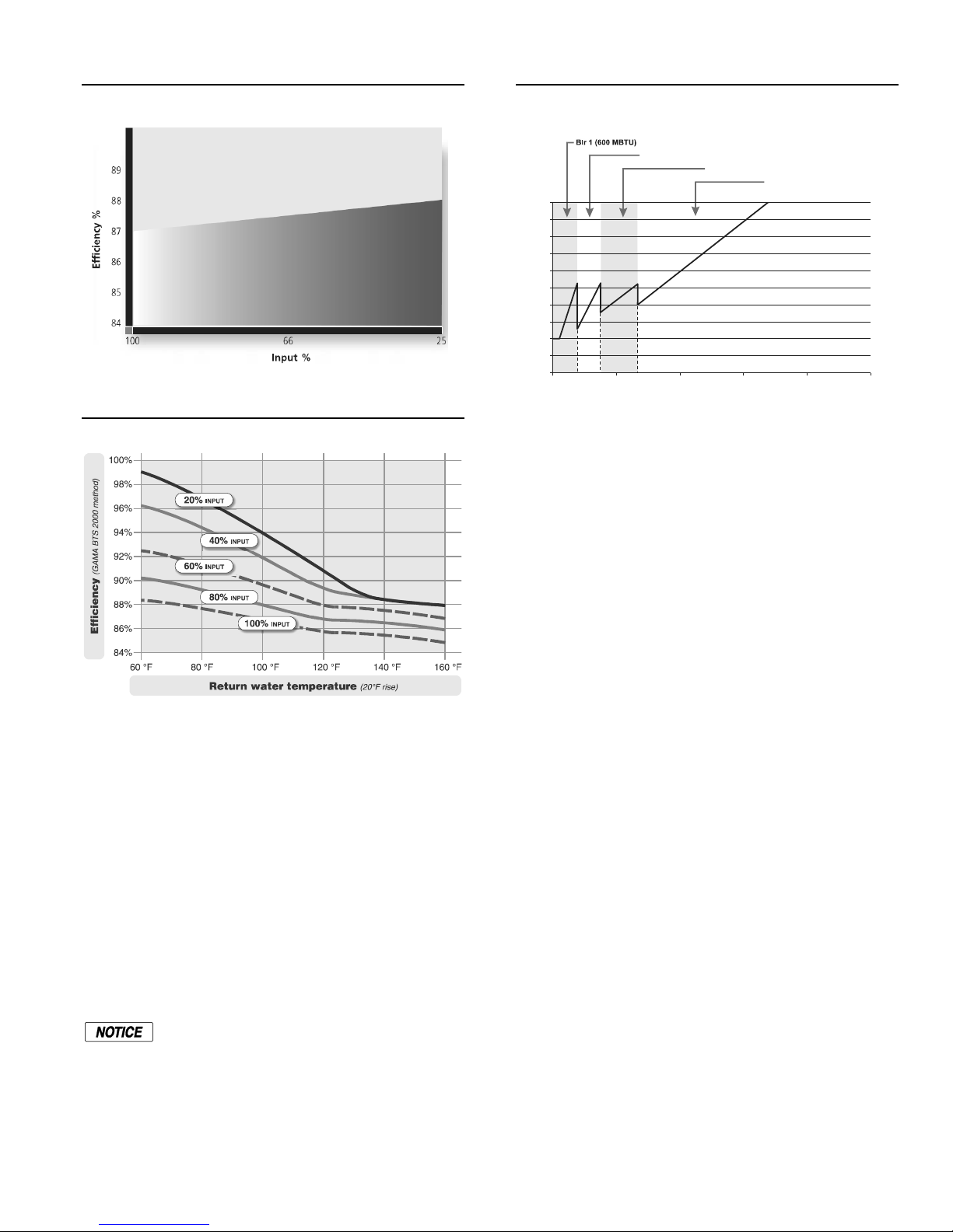
MOD-MAX the greater the combustion efficiency since it
effectively limits the input rate. The Typical Efficiency of
Non-Condensing Boilers chart can help illustrate how the
MOD-MAX value can affect the efficiency by limiting the
input until all boilers have fired. Non-condensing boiler
efficiency is relatively flat compared with condensing as
illustrated in the Typical Efficiency of Condensing Boiler
graph.
Page 14
Page 15
SETUP & OPERATION HeatNet Control REV 1.38-1
I
n
p
u
t
,
%
Figure 8
Typical efficiency of non -condensing boilers
Figure 8
(GAMA BTS2000 method)
In the first row of Figure 5 – The Mixed Boiler System table
KN6s are set as Priority 1 and 28A-W-5’s set as Priority 2.
With a MOD MAX of 54%, each KN6 can run to 324M
(648M total) before a 28A-W-5 is called ON (Add Delay
timer set long enough). Once both KN6s are running and the
28A-W-5 is called on and running, all (3) boilers will drop
to a total of the ~625M BTUs: The sum of the KN6, KN6,
and 28A-W-5. About 22% KN modulation: (.22* 600M) +
(.22* 600M) + (.33* 1.156MM) or: ~132M +~132M +
~385M = ~650M and operate at higher combustion
efficiencies. 22% is roughly between the top two lines on
the Typical Efficiency of Condensing Boilers chart for the
KN’s. The 33% is the minimum firing rate for the 28A-W-
5.
Typical efficiency of condensing boilers
‘~’ is defined as approximate
Figure 9
Boiler System Response 1
(2) KN6’s, (2) 28A-W-5’s
Blr 1+2 (1200 MBTU)
1.00
0.90
0.80
0.70
0.60
0.50
0.40
0.30
0.20
0.10
0.00
0 1,000,000 2,000,000 3,000,000 4,000,000 5,000,000
System Load , Btu/Hr
Blr 1+2+3 (2356 MBTU)
Blr 1+2+3 +4 (3512 MBTU)
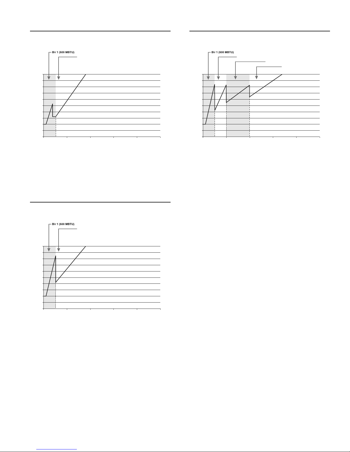
Figure 9 - Boiler System Response 1 chart illustrates how
each boiler (in the example) is brought on and fires to 54%,
drops to a lower fire rate and then adds the next boiler
(vertical dashed lines). Once all boilers are firing, the
modulation is released allowing all boilers to fire to 100%.
So, for the first 1270 MBTH of load, the combustion
efficiency is maximized by running the boilers from low to
middle input rates.
Now if a (2) boiler system using (1) KN6 with (1) 28A-W-5
and MOD-MAX set to 54, the KN6 would fire to 324
MBTUs and wait for the 28A-W-5 (Figure 10 - Boiler
System Response 2 graph). Once the 28A-W-5 fired, the
modulation would drop down and the input rate would jump
to 505 MBTUs, 385M (28A-W-5 @ 33%) + the 120M
(KN6 @ 20%). The system load was looking for 324
BTUs, but there would be 181 MBTUs more than needed.
The PID algorithm would then compensate for the large
discontinuity (over fire bump) in BTUs and the 28A-W-5
would shut off (short cycle). This discontinuity is observed
in the graph below, (Figure 10 - Boiler System Response 2
graph) where the jump from the KN6 @54% to the firing of
the 28A-W-5 is apparent.
Page 15
Page 16
SETUP & OPERATION HeatNet Control REV 1.38-1
I
n
p
u
t
,
%
I
n
p
u
t
,
%
I
n
p
u
t
,
%
Figure 10
Boiler System Response 2
(1) KN6’s, (1) 28A-W-5’s, 54% Mod-Max
Blr 1+2 (1756 MBTU)
1.00
0.90
0.80
0.70
0.60
0.50
0.40
0.30
0.20
0.10
0.00
0 1,000,000 2,000,000 3,000,000 4,000,000 5,000,000
System Load , Btu/Hr
To correct this would require the KN6 to set the MODMAX to roughly 85% (Boiler System Response 3) in order
to have a linear BTU transfer when the 28A-W-5 is added
(fired).
Figure 11
(1) KN6’s, (1) 28A-W-5’s, 85% Mod-Max
Boiler System Response 3
Blr 1+2 (1756 MBTU)
1.00
0.90
0.80
0.70
0.60
0.50
0.40
0.30
0.20
0.10
0.00
0 1,000,000 2,000,000 3,000,000 4,000,000 5,000,000
System Load , Btu/Hr
A system employing redundancy, where (1) Priority 1 is
allowed to be taken offline is shown in the Boiler System
Response 4 chart. The example system uses (2) KN6s and
(2) 28A-W-5s. Two of the KN6s are treated as one when
adding the min inputs of the Priority 1 set.
Figure 12
Boiler System Response 4
(2) KN6’s, (2) 28A-W-5’s, 85% Mod-Max
Blr 1+2 (1200 MBTU)
1.00
0.90
0.80
0.70
0.60
0.50
0.40
0.30
0.20
0.10
0.00
0 1,000,000 2,000,000 3,000,000 4,000,000 5,000,000
System Load , Btu/Hr
Blr 1+2+3 (2356 MBTU)
Blr 1+2+3 +4 (3512 MBTU)
The mixed system may also have boilers with condensing
and non-condensing types as has been illustrated. The
reason for creating a mixed system is primarily to control
the system cost.
In summary, the system should be tuned using the boiler
selection charts and the MOD-MAX value so that boilers
are brought on and fired in their respective efficiency curve
while maintaining continuity in BTUs. Since selecting the
Priority 1 boiler is integral to the fault tolerance of the
system, it is important to note any discontinuities in BTUs if
a Priority 1 boiler fails when multiple Priority 1 boilers are
used.
Page 16
Page 17

SETUP & OPERATION HeatNet Control REV 1.38-1
Master
Base Loading, Relay Control
The control has the ability to control (1) base load boiler
using the K8 Relay contacts on J4 terminals 1 & 2. In order
to connect to this plug, (2) wires are required and connected
to J4. Base Loading via relay requires these (2) flying leads.
These (2) wires then make up the Normally Open contacts.
The solid state relay K8, with contact connections on J4.1 &
J4.2 has a rating of: 0.1 to 1 Amp.
If the base load boiler is of the modulating type, a 0-10VDC
signal is also provided on J4 pins 4- and 7+. Two additional
wires will need to be added to the J4 pins at 4- & 7+. Pin 7
is the + output of the 0-10VDC transmitter, and pin 4 is the
– output. This modulating control signal is used to modulate
the base load boiler along with the HeatNet boilers in
parallel. The ADAPTIVE MOD does not function in
lowering the modulation rate when the base load boiler is
added. The PID will adapt to the newly fired base load
boiler and lower its modulation rate when the increase in
water temperature is observed.
Figure 13
BASE LOADING menu
(master boiler only)
SYSTEM menu
( )master boiler only
Enable the base load feature by setting
1. ADVANCED SETUP:SYSTEM:OPTION to BASE
LOAD. This sets the OPTION Relay to be used as
control for a Base Load Boiler.
2. The ADVANCED SETUP:BASE LOAD BOILERS:
BASE LOAD BOILERS: to 1. Currently only allows
(1) base load boiler.
3. The START & STOP qualifier condition to the method
discussed below.
Base loading with Smith Boilers
HeatNet Enabled 28A
>BASE LOAD BOILERS:1
START>MOD 95
STOP FIRST
DELAY TIME 10mins
>BOILER TYPE
LOAD FIRMWARE
OPTION: BASE LOAD
Base load
Non - HeatNet
4. The DELAY TIME to the amount of time required after
the start qualifier condition has been met to start the
boiler.
If a MINIMUM OFF time of the Base Load boiler is
needed, the Base Load boiler will share the MIN OFF TIME
of the boiler controlling it. If the base load boiler was
running and shuts off, the MIN OFF TIME will need to
expire before the boiler can start again. Once this time
expires, the DELAY TIME also needs to expire to start the
boiler. This will help in minimizing short cycle conditions
and can be set at: ADVANCED SETUP:FIRING MODE:
MODE:MIN OFF TIME.
Preferred Example Base Load:
A modulating base load boiler that can accept a 0-10VDC
control signal such as the Smith 28 series is preferred. A
135 ohm input for the base load boiler will need a converter
from 0-10VDC to 135 ohm if using KNs as the primary
HeatNet boiler. The Smith HeatNet control has the 135 ohm
feature built in.
Using the Smith HeatNet control on one Smith series boiler
can allow a second Smith series boiler or other boiler type to
be controlled using the base load feature.
http://www.Smithboiler.com/
If the base load boiler is not of the modulating type,
stopping the Base Load boiler will require that the size of
the Base Load boiler in BTUs is known relative to the
HeatNet boilers. Boiler selection is ideally; having more
total BTUs in the HeatNet boilers than total BTUs of the
Base Load boiler. This will prevent short cycling. Example:
(4) 2 million BTU HeatNet boilers = 8 million BTUs and
(1) 6 million BTU Base Load boiler.
When all (4) HeatNet boilers are running @ 99%, the Base
Load boiler is called on (demand is approx. 8 million
BTUs). As the Base load boiler comes on it introduces 6
million BTUs and the HeatNet boilers modulate down to
25% for a total output of 2 million BTUs and running at
high efficiency. The HeatNet boilers can now modulate to
the load from 1.6 million BTUs (20% mod) to another 8
million BTUs.
Not Preferred Example Base Load:
Example of having a larger Base Load boiler that is not
of the modulating type: If there is a 6 Million BTU Base
Load boiler running with (3) 2 million BTU HeatNet
boilers, a short cycling situation will arise when the (3) 2
million BTU boilers are running @ 99% and the Base Load
boiler is called on. At this point there is a need for
approximately 6 million BTUs. The (3) smaller boilers will
then modulate down to low fire. At this point, the (3)
smaller boilers need to shut off or the Base load boiler needs
to shut off. There is no overlap. A selection for stopping the
boiler now needs to be determined. Setting the Stop
Page 17
Page 18
SETUP & OPERATION HeatNet Control REV 1.38-1
qualifier; Modulation to 40% or a low fire rate will shut the
Base Load boiler off and allow the (3) smaller boilers to
modulate up again (short cycle of the Base Load boiler; Use
the Delay Timer and Min OFF timer). The Stop qualifier;
OA T > xxF may also be used if the system design
temperature is known. Then let the Base Load boiler cycle
Figure 14
Base Load Relay Wiring
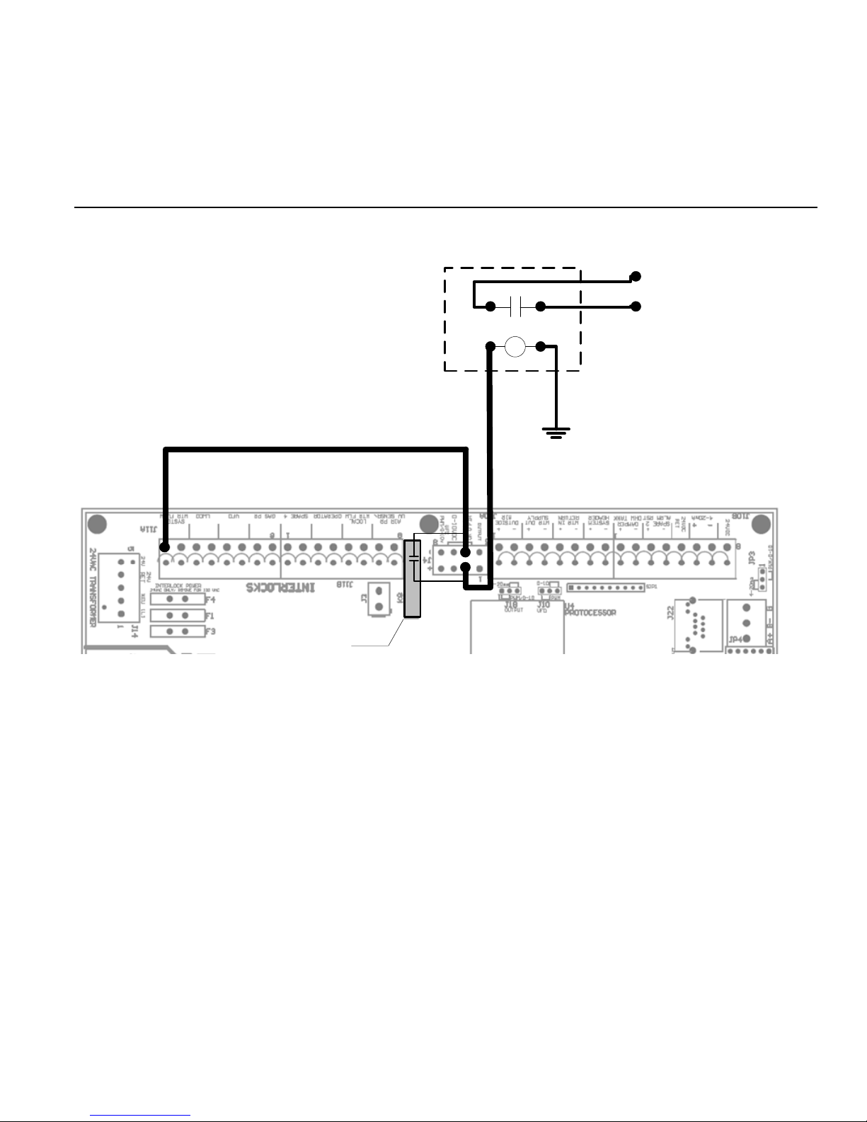
1. First ensure that the ADVANCED
SETUP:SYSTEM:OPTION: is set to BASE
LOAD. The Base Load Relay (K8) will not be
enabled/used unless this is selected.
2. Now, The ADVANCED SETUP:BASE
LOAD:BASE LOAD BOILERS: must be set to 1.
3. When the START condition in the BASE
LOAD BOILERS menu is met, the K8 relay will
close. But, only when the DELAY TIME under
the BASE LOAD BOILERS menu expires.
24 VAC
off its limits, whether a 2 stage, Hi/Lo, or modulating boiler.
The default setting is for the Base Load boiler to stop first
once the water temperature exceeds the top of the heating
band.
Base Load RIB Relay
Enable Input on
Base Load Boiler
24 VAC Return, or
Chassis Ground
Base Load Relay
Page 18
Page 19

OPTIONAL FEATURES HeatNet Control REV 1.38-1
Setting up base loading
The base load boiler is controlled using a set of contacts to
enable it (location J4). Enabling/Disabling this relay contact
can be done using any combination of (3) qualifiers to start
the boiler and (4) to stop the boiler. These qualifiers are:
1. Modulation %:
a. START menu item: The relay contact will close
when the MOD % from the Master boiler exceeds
this value. ADVANCE SETUP:BASE LOADING:
START>MOD
b.
STOP menu item
when the MOD % from the Master boiler falls
below this value.
LOADING: STOP<MOD
If the START>MOD value is set to a value
higher than the ADVANCED SETUP:MOD-
MAX: all boilers will be firing before this
modulation rate is reached. This will ensure
that all available boilers are firing before the
base load boiler relay is enabled.
c. Setting the : STOP<MOD to a % value slightly above
the min fire rate % of the system will ensure that the
base load boiler will stop before the first condensing
boiler stops. This is due to the Modulation rate being
close to the min modulation rate before the water
temperature exceeds the top of the heating band.
2. Outside Air Temperature:
a. START menu item: The relay contact will close to
enable the boiler when the OA T read from the
Outside Air Temperature sensor (if Equipped) falls
below this temperature. ADVANCE SETUP:BASE
LOADING: START< OA T
b. STOP menu item: The relay contact will open to
disable the boiler when the OA T read from the
Outside Air Temperature sensor (if equipped) rises
above this value. ADVANCE SETUP:BASE
LOADING: STOP> OA T
: The relay contact will open
ADVANCE SETUP:BASE
3. Return Water Temperature
4.
a.
START menu item
to enable the boiler when the RET read from the
Return Water Temperature sensor (if Equipped)
falls below this temperature.
SETUP:BASE LOADING: START> RET
b.
STOP menu item
to disable the boiler when the RET temperature
read from the Return Water Temperature
sensor (if Equipped) rises above this
temperature.
LOADING: STOP< RET
:
FIRST
a.
STOP menu item
to disable the boiler when the temperature
exceeds the heating band. This gives the result
of stopping the Base Load boiler First. Default
setting.
: The relay contact will close
ADVANCE
: The relay contact will open
ADVANCE SETUP:BASE
: The relay contact will open
Delay Time
The DELAY TIME is also included to hold off starting the
boiler until the delay time is met. Once the start condition
qualifier term is met, the DELAY TIME will start counting
down. When the time expires, the base load relay contacts
will close. ADVANCE SETUP:BASE LOADING:DELAY
TIME. It is adjustable in a range of: 0 to 60 minutes.
Base Load Failsafe
If there are no boilers available to fire (offline or faulted) and
there are no boilers in local override, and there is a call for
heat, The J4 Base Load relay will close. If a boiler becomes
available and needs to fire, the Base Load boiler will remain
firing until the temperature exceeds the band. This is provided
to keep the system from entering a no heat situation.
If the OA T qualifier is used as the Start and
Stop qualifier, ensure that there is at least a few
degrees difference for hysteresis.
Page 19
Page 20

OPTIONAL FEATURES HeatNet Control REV 1.38-1
Heating Control Methods
An overview of the (5) methods for controlling the Smith
series boiler are presented here. They are outlined in more
detail at the end of this section. See Error! Reference source
not found., page Error! Bookmark not defined., through
Error! Reference source not found., page Error!
Bookmark not defined..
Heating Method 1
The first method is to use the Smith Series boiler in its standalone modulating method. This method uses a PID algorithm
to maintain a setpoint and is enabled using the HEAT
DEMAND input. Closing a relay contact or switch across the
HEAT DEMAND input will cause the Master boiler to
control all member boilers using H-Net.
A member boiler may also be controlled by the HEAT
DEMAND input (LOCAL mode). The member boiler will
then ignore commands from the Master and maintain its
LOCAL SETPOINT at the supply sensor.
Heating Method 2
The second method is to view the Smith boiler as two
separate boilers or as a HIGH/LOW boiler using T1 & T2.
Heating Method 3
The third method is to allow a remote 4-20 ma or 0-10 VDC
signal to control the firing rate (modulation) of the boiler
using the 4-20ma input, along with the 4-20ma REMOTE
ENABLE input.
Short cycling may occur when a firing rate is
sent to a member boiler that would cause the
supply temperature to rise high enough to trip
the operating limit (low flow rate). After the
supply temperature falls, the boiler would
restart and the process may continue. A
member boiler would use its supply (outlet)
sensor to protect itself from short cycling by
limiting the firing rate coming from the Master.
This occurs in the event that the member’s
supply temperature increases above the
(OPERATE LIMIT- OPERATE LIMIT
BAND).
Operating Limit
When the master boiler or an external control input is used to
control a member boiler (i.e. AA, T1-T2, 4-20ma, H-Net), a
software operating limit on the member boiler will be used to
limit the maximum output of the member boiler. This
operating limit can be adjusted in the
SETUP:SETPOINTS:OPERATING LIMIT.
There is also an associated operating limit band that must be
set in conjunction with the operating limit to help prevent this
LIMIT from being reached. Its purpose, is to limit the output
of the boiler as it approaches the operating limit. If the band is
set to 10 degrees, then for every degree that it approaches the
operating limit, the maximum output will be lessened by 10%.
With a band of 20 degrees, for every degree that it approaches
the band, the maximum output will be lessened by 5%. You
can think of this operating limit as a smart aquastat which
prevents the High Limit from tripping. This method
minimizes boiler short cycling when using external inputs.
The minimum setting is 1 degree and effectively turns the
limit band OFF. The default setting is 20F.
Heating Method 4
The fourth method turns the boiler ON and OFF @ 100%
modulation using the AA terminal.
Heating Method 5
The fifth method uses an RS485 digital communications cable
with the MODBUS protocol. The boiler is controlled by
writing and reading registers using MODBUS commands. A
bridge module may also be used to convert BACnet or
LonWorks protocols to MODBUS.
Page 20
Input Priorities
The Smith-Series control inputs are prioritized so that
multiple levels of external control can be employed at the
same time. This means that if we are firing the boiler with a
low Priority input and a higher Priority input is called for, the
boiler will now fire at the higher Priority input. When the high
Priority input is removed, the boiler will revert back to the
lower Priority input that is still being called.
Priority 1
The AA terminal has absolute control, and if used, will
always fire the boiler at 100% output, regardless of any other
input. The 4-20mA input may be raised to this Priority using
ADVANCED SETUP: 4-20mA INPUT:PRIORITY.
Priority 2
The HEAT DEMAND input is the next, and provides the
means to operate the boiler in LOCAL MODE when an
external control is not present, has failed, or needs to be
Page 21

OPTIONAL FEATURES HeatNet Control REV 1.38-1
enabled or disabled. A member can override the H-Net
commands using this input.
Priority 3
If a HeatNet (H-Net) Network cable is connected between
boilers, and one is configured as a MASTER (requires
HEADER sensor), then the MEMBER boilers will be
controlled over the network by the MASTER.
Priority 4
The 4-20ma/0-10VDC input in tandem with the 4-20ma
REMOTE ENABLE input is next. Any signal over 4.02ma or
2.01VDC will start and operate the boiler if the REMOTE
ENABLE is closed.
Priority 5
The lowest Priority is using the boiler as (2) stages
HIGH/LOW. These are the T1 and T2 inputs.
Each of these control methods will now be explained in more
detail:
Heating Method 1
HEAT DEMAND
Closing a relay contact, switch, or jumper across the HEAT
DEMAND input will enable this method. This method allows
operation as a setpoint control. As a setpoint control, the
Master (defined by having a common system supply header
sensor), on the H-Net network can command the boiler fire
rate of all Member boilers. The Master can call as many
boilers that it has available (boilers are auto-detected over the
H-Net cable by the Master) to meet its SYSTEM
SETPOINT. The H-Net cable must be connected and will
cause the amber light on the communications board to flash.
The amber light indicates an H-Net master is broadcasting
control information and a system heartbeat.
The AA terminal, the FAILSAFE mode active, 4-20ma at
PRIORITY:HIGHEST, and the HEAT DEMAND input
(LOCAL) on a Member, are the only inputs that will override
the H-Net control.
Figure 15
Master Boiler
The MASTER boiler controls the system using a PID
algorithm. Once the boiler is started, a PID algorithm is used
to produce a modulation percentage value from 0-100%. This
percentage is converted to a PWM, (P)ulse (W)idth
Heat Demand Input
MASTER: Close contact to control all boilers and run at system setpoint.
MEMBER: Close to run at LOCAL setpoint
(M)odulation or 0-10VDC signal by each boiler. The
temperature of the water is maintained by sending this signal
to the Mod Motor, which in turn controls the damper position
and fuel rate. providing the firing rate control.
Member boiler(s)
A Member (lacking a common system supply header sensor)
boiler may also be controlled by the HEAT DEMAND input
(LOCAL mode). The member boiler will then ignore
commands from the Master and maintain its own LOCAL
SETPOINT at its supply sensor. This can be viewed as a
manual override on a member boiler. Be sure to observe the
proper use of a Common System Damper (See: AUXILIARY
FUNCTION OPTIONS section) and any system pumps or
system common interlocks.
Features of the HEAT DEMAND input include:
1. The control is designed to predict when to start and
stop the boiler and keep the setpoint in, or as close to
the control band as possible. If PREDICTIVE
START is enabled, the boiler may start when it is in
the band and not below it. This will help to maintain
a more accurate temperature relative to the setpoint.
See also: ADVANCED SETUP:FIRING
MODE:PRDICTIVE START: to disable this feature.
2. The control can also use the Outdoor Reset feature.
This feature allows the setpoint to be changed
automatically based on the outside air temperature. If
this feature is used, the control input: OR OVR
(OUTDOOR RESET OVERRIDE), can be used to
override the Outdoor Reset feature and run from the
local setpoint. A contact closure on the ‘AA’ input
can also override this method.
3. The Setpoint can be controlled remotely using the 4-
20ma setpoint control function.. This function translates a
4-20ma control signal to a setpoint mapped between 50F
and 220F. These (2) temperatures are adjustable to
provide a setpoint range. The minimum start current is
also adjustable between 3.71 and 5ma. The setpoint
control feature is used in conjunction with the REMOTE
ENABLE input on J12A. This feature is enabled in the
SETPOINTS menu as:
SETPT SOURCE 4-20ma
Page 21
Page 22
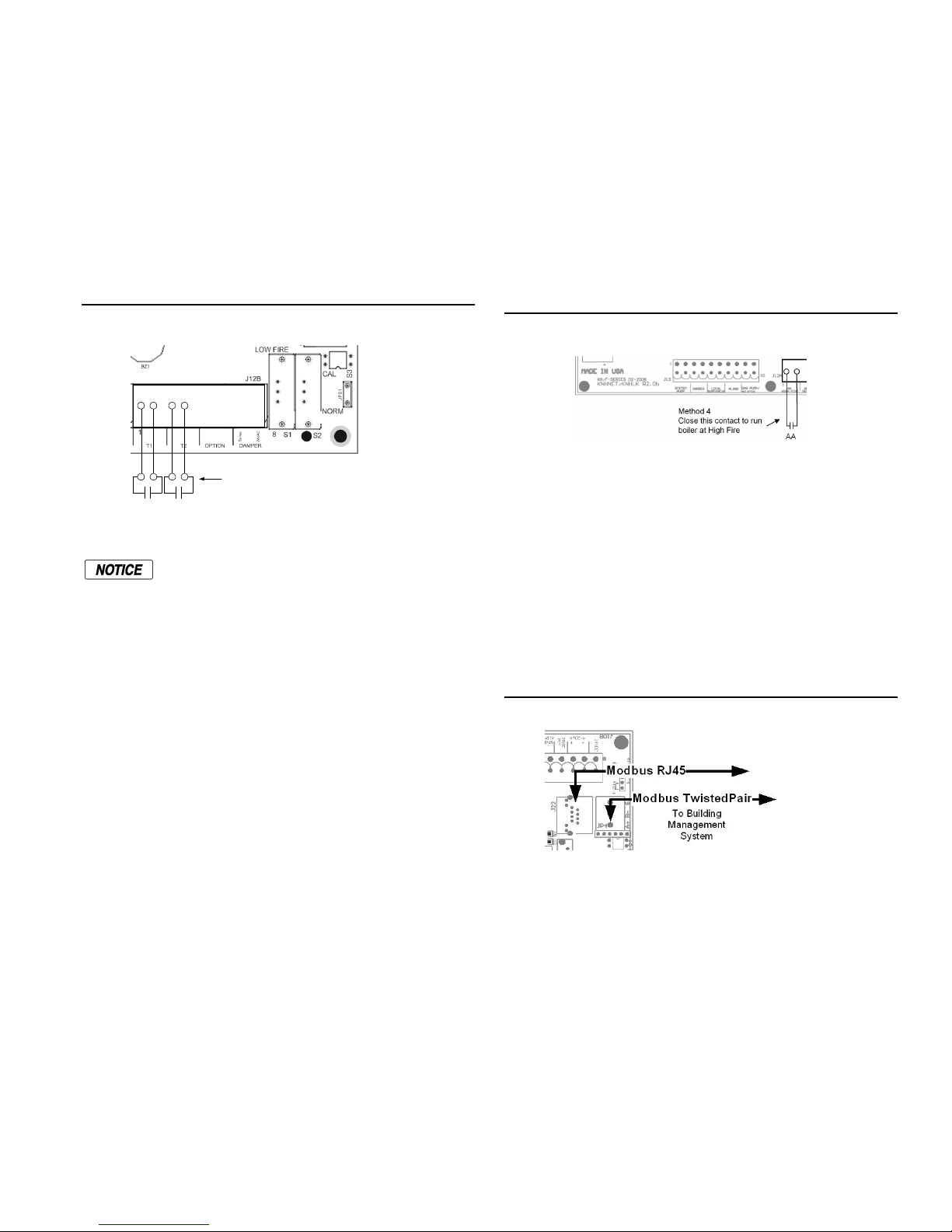
CONTROL METHODS HeatNet Control REV 1.38-1
Heating Method 2
STAGE Control T1-T2
1. Closing only one of these contacts tells the boiler to
operate at MINIMUM FIRE.
2. Closing the other contact will fire the boiler at
MAXIMUM output (the same rate as closing the AA
input).
Figure 16
The AA, HEAT DEMAND (LOCAL) input, the H-Net, the 420ma input will all override the stage control inputs
Stage Control Input
T1 T2
The maximum output of the boiler is based on
the MAX VFD setting in the calibration mode
and not the nameplate rating.
Method 2: LOW FIRE, HIGH FIRE
Close contacts here
Heating Method 3
4-20ma Control
Placing a current source between the + and – 4-20ma inputs
will allow remote control of the boilers firing rate. An
adjustable starting milliamp current signal here will start and
then fire the boiler at the minimum fire rate. See:
ADVANCED SETUP:4-20mA INPUT.
See section OPTIONAL FEATURES Using the 4-20ma input
for extensive detail.
A 20mA signal will fire the boiler at the maximum firing rate,
a 4 mA signal at the minimum rate. This means that a 20%
(4mA) input signal is required to start the boiler, but if the
boiler is classified as having example:4:1 turn down ratio, the
boiler can only be fired as low as 25% of output. Any signal
between 20% and 25 %, will fire the boiler at the minimum
fire rate of 25%. If the MINIMUM setting of the boiler is set
above the example: 4:1 turndown of 25% (such as 33%), a
control signal change between 25% and 33% will not change
the boilers firing rate. Once the control signal rises above the
MINIMUM fire rate, the control signal will then affect control
of the boilers fire rate.
The AA terminal, the HEAT DEMAND, and the H-Net
NETWORK are the only inputs that will override the 4-20ma
input.
Heating Method 4
AA Input
HIGH FIRE input Control: The AA input will fire the boiler
at HIGH fire (maximum output of the boiler). No other inputs
can override this input.
Figure 17
AA – High Fire Input
Heating Method 5
MODBUS communications
The fifth method uses an RS485 digital communications cable
with the MODBUS protocol to control the boiler using the HNet network. The Boiler or Boiler network will run as in
Method 1, but instead of the HEAT DEMAND input, a
software form of the HEAT DEMAND input is used (40001:
Boiler/System Enable/Disable). See: MODBUS
COMMUNICATIONS section. The MODBUS protocol
allows writing and reading registers using MODBUS
commands.
Figure 18
The System Setpoint Timer also needs to be loaded
periodically to allow the H-Net system to fallback to Method
1 in the event communications is lost from the Building
Management System (BMS). This feature can be disabled in
the ADVANCED SETUP:COMMUNICATIONS menu.
MODBUS Connections
Page 22
Page 23
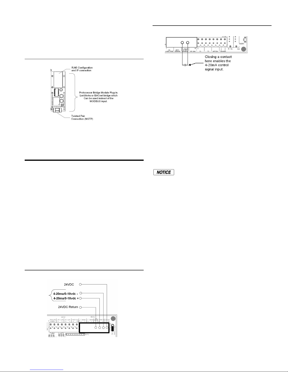
OPTIONAL FEATURES HeatNet Control REV 1.38-1
Protocessor option
An optional BACnet or LonWorks bridge module can be used
to connect the MODBUS network to a BACnet or LonWorks
network.
Figure 19
This method allows enabling and disabling the boiler or HNet system, changing setpoints, reading boiler(s) status, or
temperatures remotely using digital commands. See the
section: MODBUS Communications.
Using the 4-20mA Input
The 4-20ma input is designed to operate per the ISA-50.1
standard. It will support Type 2, Type 3, and Type 4
Transmitter/Receiver circuits.
The Type 2 and Type 3 circuit may use the supplied
+24VDC and 24VDC RET connections (J10B) to power a
remote transmitter. The –mA terminal will need to have a
jumper connected to the adjacent 24VDC RET terminal to
reference the signal ground.
With the type 4 configuration, multiple boilers (up to 5),
may be connected in series using the –ma +ma –ma +ma
scheme (no jumper to 24VDC RET). This allows one 420ma transmitter to control multiple boilers. A free-floating
250 ohm resistor is viewed by the BMS (or external
control’s) 4-20ma transmitter across the + and –4-20ma
terminals with this method.
Figure 20
MODBUS Connections
(OPTIONAL)
4-20mA Connections
Figure 21
The 4-20 ma input uses a 250 ohm sense resistor to convert
the current to a voltage from 1 to 5 volts DC for the control to
use. For this reason, a 1-5 VDC control voltage may also be
used across the 4-20mA +/- input, but it still needs to supply
the necessary current, i.e. 20mA. This resistor is located on
the bottom side of the control board. When a 4.02 mA
(adjustable) signal is sensed, the boiler will initiate a start
sequence and fire the boiler at its minimum setting if the
REMOTE ENABLE input is closed. This is typically 33%(3:1
turndown) or 25%(4:1 turndown) of the boilers output.
If jumper shunt JP3 is set to the PWM/0-10 position, the 420mA input will accept a 0-10 VDC signal (that can source
20mA). The operating range will be from 2-10 VDC or twice
what was previously stated for the 1-5 VDC functionality. To
convert a 0-10VDC signal to mA, divide by 500 (ohms).
If using a remote panel with a relay and a 4-20 mA transmitter
for operation, connect the 4-20mA transmitter output from the
remote panel to the member boilers using the floating 250
ohm method (type 4). The relay contacts on the remote panel
will then be connected to the associated 4-20mA REMOTE
ENABLE inputs on the associated boiler(s).
Setpoint Control functionality can be implemented remotely
using the 4-20mA input. This function translates a 4 to 20mA
control signal to a setpoint mapped from 50F to 220F. The
feature is enabled in the SETPOINTS menu as: SETPT
SOURCE 4-20mA.
ADVANCED SETUP:4-20mA INPUT. Also, when
selecting; SETUP:SETPOINTS:SETPOINT SOURCE and
selecting 4-20mA, the 4-20mA INPUT menu will be
automatically entered.
The current at which the boiler will start can be selected. It is
adjustable from 3.7mA to 5mA. Hysteresis of .1mA is always
in effect. So, if the starting mA = 4.10mA the boiler will start
when the control current applied achieves the value of
4.10mA. The boiler must drop .1mA below this to turn OFF,
4-20mA Enable Connection
Due to the inability of control voltage methods
(1-5, 2-10 VDC) to reject noise, the use of the
4-20mA control current is recommended. The
control voltage methods may be less expensive,
but are the least stable. If using a 0-10VDC
control signal, a source current of 20mA is
required.
Page 23
Page 24

OPTIONAL FEATURES HeatNet Control REV 1.38-1
in this example 4.00mA. This hysteresis value is not
adjustable.
When using the 4-20mA setpoint control, a band may be set at
which the 4-20mA signal will operate over. The lower
setpoint is defined as 4mA SETPOINT and the upper setpoint
is defined as 20mA SETPOINT. The 4mA SETPOINT is
linked to the BOILER START x.xxmA where this starting
current is the lower setpoint. So if the 4mA SETPOINT is set
to 130F and the 20mA SETPOINT is set at 180F the band will
be established. Once a starting control current of BOILER
START 4.1mA is applied, and the 4-20 REMOTE ENABLE
INPUT is closed, the boiler will start and the setpoint will be
set to 130F. If a control current of 10mA is applied, the boiler
will track on a linear slope towards the 20mA SETPOINT
settling at a SETPOINT of ~149F. As the current increases to
20mA, the SETPOINT will indicate 180F. The Default setting
is 4mA SETPOINT: 50F, and 20ma SETPOINT 220F.
Anytime a new firmware version is uploaded to
the control, these values return to these
defaults.
If using the direct modulation mode by applying a 4-20mA
current, only the BOILER START x.xx setting applies.
The 4-20 mA input can also be set to HIGH PRIORITY. This
can be set in menu: ADVANCED SETUP:4-20mA INPUT.
This allows a member boiler to be taken offline and directly
modulated by an external control. If the Master is using it for
heating and the 4-20mA is set to HIGH PRIORITY, an
external control can now output a 4-20mA signal which will
take over the boiler’s fire rate. This is typically used for DHW
control.
Circulator Pump Options
The control has provisions for a system pump and a local
pump/valve. This is to allow for primary/secondary loop
configurations. The system circulator pump is implemented
using the K4 relay and normally open contacts at J13
marked SYSTEM PUMP.
The pumps require motor contactors to isolate
the on-board relay contacts. The on-board
relays should never be used to energize pumps
directly.
Figure 22
Pump Connections
Operator
System Pump
Combustion Air Damper Local Pump/Valve
The System Circulator Pump is supported by (2) modes and
a special feature.
DHW Pump/Valve
Alarm
1. The first mode will allow the circulator pump to remain
on, unless the control’s outside high air temperature
setting has been met when using OUTDOOR AIR
RESET.
2. The second mode will allow the circulator pump to be
turned on whenever there is a call for heat (any control
input). This mode will stop the circulator pump when the
call for heat is lost and the pump post purge time has
been satisfied.
The summer pump jog is a special feature that can be
selected when the system is in Warm Weather Shutdown
(OUTDOOR RESET). The jog allows the system circulator
pump to run for the pump purge time once a week. It can be
set to any day of the week and will occur at 12:01 AM.
The system flow proving switch is implemented using
System Water Flow on J5B. If a local flow switch is
connected to the WTR FLW LOCAL interlock, the HeatNet
control will wait up to 240 seconds to prove flow. This time
is adjustable under SETUP:PUMP OPTIONS. The default
flow proving time is 10 seconds. It can be increased to allow
slower valves to open before flow is established. If flow is
interrupted after it has been established, an error will be
displayed and the boiler will cycle OFF. As long as there is
a call for heat, every 10 minutes the circulator pump will try
to re-establish flow and start the boiler again.
The Local Circulator Pump is supported by (3) modes and
(2) features.
1. The first mode allows the circulator pump to remain
on, unless the control’s outside high air temperature
setting has been met when using Warm Weather
Shutdown.
2. The second mode will allow the circulator pump to be
turned on whenever there is a call for heat (any control
input). This mode will stop the circulator pump when
the call for heat is lost and the pump post purge time
has been satisfied.
3. The third mode works much the same as mode 2, but it
allows the inlet sensor (RETURN) to be used with the
outlet sensor (SUPPLY) to keep the pump on until a
delta (difference) temperature is met. A return
temperature sensor is required for this mode, because
the delta temperature (SUPPLY – RETURN) measured
is across the boiler. In this mode, the post purge time is
also used. After the delta temp has been met, the post
purge time needs to expire before the pump is turned
off. This mode works much the same as mode 2.
PUMP/VALVE OPTION: This is a special feature of the
local circulator pump to prevent deadheading water flow
when all boilers are off. When this feature is enabled, the
master boiler will enable its local circulator pump/valve
when NO boilers are running. If boilers are running in
LOCAL override and not controlled by H-NET, but are
Page 24
Page 25
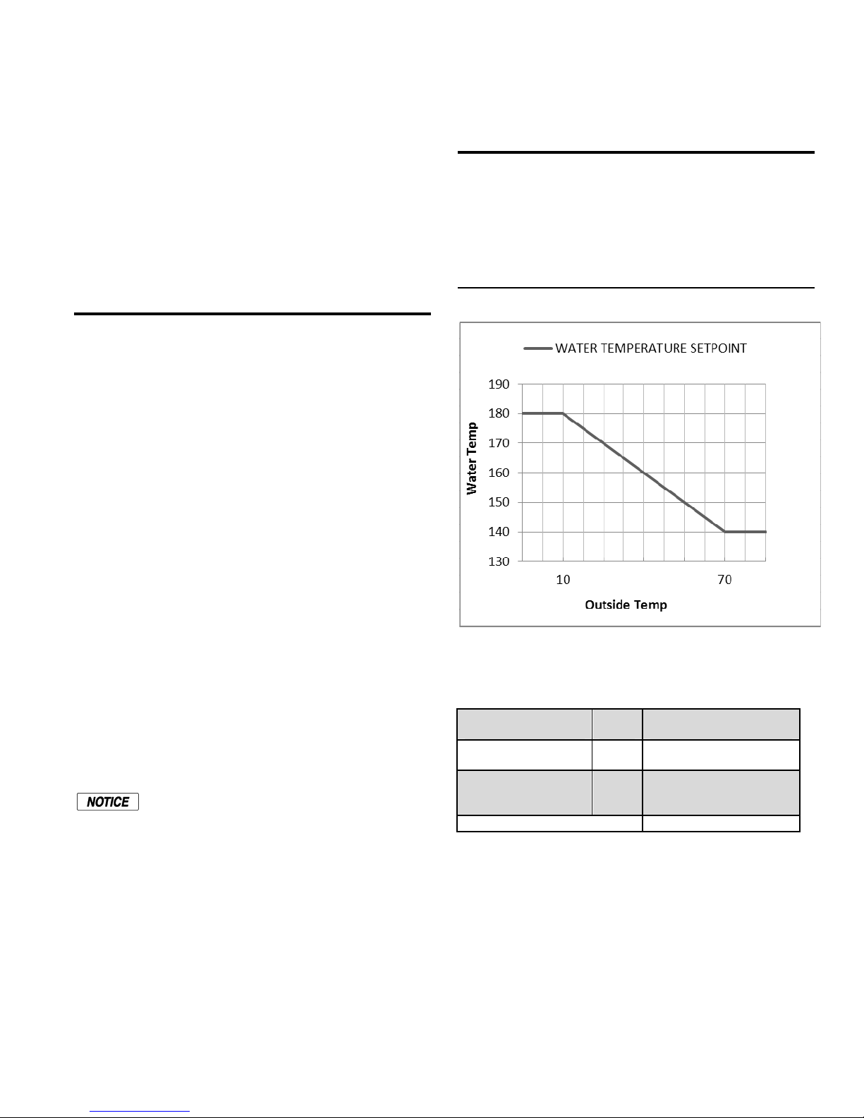
OPTIONAL FEATURES HeatNet Control REV 1.38-1
WATER TEMP
180°F
Water temp @
visible to H-NET, the pump(s) on these boilers are presumed
ON. In this situation, the master will not enable its circulator
pump/valve unless it is running.
Another feature of the HeatNet Control is to control a local
(primary) pump using a Variable Frequency Drive. This
feature may be required when a secondary system pump is
also variable speed. To enable this feature: SETUP:PUMP
OPTIONS:LOCAL PUMP PUMP/VALVE
OPTION:LOCAL PUMP VFD: ON. Setting this Option to
ON will map the 0-10VDC control signal on J4 pins 7+ and
4- to the modulation rate. (2) wires need to be run from J4.7+
and J4.4- to the VFD’s input connection
Auxiliary Functions
Relay K5 and the terminal J13 is used to control a combustion
air damper. The input J12B is used to detect the dry contact
proof switch from the damper. A proof time of up to 4
minutes can be set before the boiler can start or an alarm
condition will occur. The Combustion Damper can be setup in
the SETUP:AUX FUNCTIONS menu.
The Master boiler controls the system damper, so in the event
this damper fails to open, the system will not start. If the
Master boiler’s system damper fails, then no call for heat will
be made to the member boiler(s).
Each member boiler can control its own damper and is
independent of the Master boiler when a call for heat is made
to the member. This allows for separate dampers for each
member boiler. They can be wired to J12B terminals 7 and 8.
If a common system damper is used (controlled by the Master
boiler), each individual boiler must prove that the combustion
air damper is open when it is placed in LOCAL. This may be
done using J12B terminal 7on the all boilers wired to the
damper’s prove switch. Terminal 7 is the sense input and
terminal 8 is 24 VAC. Connecting a wire to terminal 8 is not
recommended.
See Figure 35, Common System Damper Wiring, Page 42.
A separate/independent 24 VAC source is
recommended to be used for the damper prove
switch when a common system damper is used.
If you use terminal 8 to supply power from the
Maste,r and the Master is powered OFF, no
boiler will be allowed to fire due to the loss of
power through the prove switch. A backup
boiler will also need to have the damper relay
contacts wired in parallel with the Master for
when the Master is powered OFF.
A second wire on the Master J12B terminal 7 is then
connected. The other end of this wire is then run to the first
Member boiler J12B terminal 7. If another member boiler is
present, a second wire can be connected to the first member
boiler J12B terminal 7 and the other end connected to the
other boiler J12 terminal 7. This method can be continued if
additional boilers are present. This input must be selected in
the SETUP:AUX FUNCTIONS:COMBUST AIR DAMPER
menu.
Outdoor Reset
The Outdoor reset feature allows the water setpoint
temperature to change dynamically with the outside air
temperature. It also provides an adjustable temperature that
shuts the boiler/boiler system down when the outside
temperature rises above it.
Figure 23
Outdoor Reset Curve, Typical
The above chart shows how the water temperature setpoint
changes with the Outside air temperature. The four values of
180, 10 and 140, 70 are the default values:
LOW OA TEMP
WATER TEMP
HIGH OA TEMP
WWS Setpoint 72°F Outside air temperature
WARM WEATHER SD=ON If set to ON here
10°F
140°F
70°F
outside air temp
Water temp @
outside air temp
where Warm Weather
Shutdown occurs
The chart depicts what the water temperature setpoint will
equal with a corresponding outside air temperature. At an
outside temperature of 10F and below, the water temperature
setpoint will be limited to 180F. With an outdoor temperature
of 70F and above, the water temperature will be limited to
140F. The water temperature setpoint will track along the
charts plotted line with corresponding outside temperatures.
The OR OVR (Outdoor Reset Override) input on J12A can be
used to override this Outside Air Setpoint and maintain the
water setpoint at the LOCAL or SYSTEM SETPOINT value
Page 25
Page 26

OPTIONAL FEATURES HeatNet Control REV 1.38-1
when a contact is closed across this input. This can be used as
a Domestic Hot Water demand input.
Another function of the OUTDOOR RESET is the
Winter/Summer mode ( (W)arm (W)eather (S)hutdown).
With the WWS SETPOINT set to 72F and WARM
WEATHER SD set to ON, the boiler/system will enter
summer shutdown when the Outside Air temperature rises
above 72F. While in this state, the OR OVR input on J12A
can be used to bring the boiler/system on to maintain the
water setpoint at the LOCAL or SYSTEM SETPOINT value.
During WWS operation, the System pump will not be enabled
just the Local pump unless the SETUP:SYSTEM
PUMP:OVR ENAB IN WWS is set to ON. This is the System
Pump priority mode. When SETUP:SYSTEM PUMP:OVR
ENAB IN WWS is set to OFF, the system pump will not
come on while in WWS with the OR OVR override input
closed.
Sensors
The Smith HeatNet control supports a standard 10K
thermistor (Type ACI/10K-CP). These sensors can be
calibrated to the control by entering the sensor menu and
placing a precision 10k resistor on an input.
Immersion sensors must have wells.
Security
A password can be used to lock out control and setup features.
It can be enabled, but is shipped in the disabled state.
Diagnostics
The Smith HeatNet control can display and identify faults in a
meaningful way. If an interlock trips, it will be indicated in
the main screen display, along with an audible alarm
(mounted on control board) and a set of relay contacts will
close. A record of this, with a time stamp, will also be entered
into the log as an aide in the diagnosis of the event. The log
can be downloaded and a histogram used to display the data.
If using Modbus, BACnet, or LonWorks, software flag bits in
registers are available.
Open and shorted sensors are checked continuously, so that in
the event of a sensor failure, the system shuts down and the
alarm relay is closed.
If a pump fails (flow switch required), or the flow switch
fails, the boiler will cycle the start condition every 10 minutes
in an attempt get the boiler restarted.
The damper fails to open and never closes its proof switch, a
retry algorithm will attempt a retry. Every 10 minutes the
damper relay will cycle and try to open the damper again.
If the H-Net control closes the last interlock string connected
to the ignition control and the ignition control never closes its
Blower Relay, the H-Net control will wait 2 minutes. The HNet control will then retry for the duration of the local pump
post purge time and then retry the ignition sequence. During
this time “retry strt” will be displayed in the status screen.
After (5) attempts the H-Net control will lock out and display
call service.
Communications
The Smith HeatNet control has the ability to communicate
using the MODBUS protocol with a building management
system. Most registers and functions are available for
MODBUS access. Access is allowed using the RS485
MODBUS PORT connecter.
An optional BACnet or LonWorks bridge module can be used
to connect the MODBUS network to a BACnet or LonWorks
network. See Heating Method 5 control.
Failsafe Modes
Failsafe Modes have been added to help protect systems from
no heat conditions. When using one of these modes ensure
that you connect any DAMPER control, or system pump
control to safely allow operation with the assumption that
the MASTER boiler or BMS system is DOWN. (See Figures
35 and 36)
FAILSAFE REQUIREMENTS:
1. Since the Member boiler that will be assigned the
Failsafe duty will always turn the system pump ON, this
boiler should not be used for DHW heating. If the Master
controls the system pump, then the Failsafe Member
boiler would need to control the system pump in parallel
with the Master boiler. Wire the System Pump contacts in
parallel with the Master.
2. If the combustion air damper is used as a common system
damper, the Failsafe boiler should be wired to control the
damper in parallel with the Master boiler.
3. The Failsafe boiler should have the LOCAL SETPOINT
set to the same setpoint temperature as the Master
boiler’s SYSTEM SETPOINT.
Be aware that the boiler may start without a call-for-heat
in the FAILSAFE MODES. FAILSAFE MODES can be
accessed through the:
SETUP:AUX FUNCTIONS:FAILSAFE MODES
Page 26
Page 27

OPTIONAL FEATURES HeatNet Control REV 1.38-1
The following are types of Failsafe
conditions.
1. Building Management System Failure
If a BMS system is controlling the setpoint and enabling
the boiler system, a timer is provided to allow operation
of the system in the event that communications are lost
with the BMS system. The HeatNet boiler system will
run locally if communications is lost and this timer
expires due to the lack of being updated.
The system setpoint timer and system setpoint work in
tandem to externally control (i.e. a BMS - building
management system) the operating setpoint. The setpoint
(countdown) timer should be loaded with a timeout value
(in seconds) prior to writing the system setpoint. When
the timer reaches zero, the control assumes that the BMS
is no longer operating and the local setpoint (saved on the
control) is reloaded. If the setpoint timer is not written, a
default timeout value of 60 seconds is assumed. The
timer is automatically reloaded with the default value
when a setpoint is written.
The BMS mode is always on and no menu
item is available.
2. Heat HeatNet Communications Lost
SETUP:AUX FUNCTIONS:FAILSAFE MODES:
H-NET COMM LOST:
This mode allows a member boiler to run in LOCAL if
the communications link via the H-NET cable is lost.
This includes the MASTER boiler losing its Control
board, Communications board, or the power on the
MASTER is switched OFF. When this MODE is set to
ON, and if the member boiler loses it’s link (heartbeat
packet over the H-NET cable) to the MASTER Boiler,
this MEMBER will fire to the LOCAL setpoint.
The heartbeat packet over the H-NET cable
needs to be lost for 10 minutes
This mode may be used by the MASTER or MEMBER
boiler, and can be used as a type of freeze protection. In
this mode you may select which Sensor you wish to
monitor, or you may opt to turn this mode OFF. If you
select a sensor, you may then associate it with a
temperature at which the boiler will turn ON. Once the
temperature at this sensor falls below the LOW TEMP
temperature the boiler will start and fire to its LOCAL
setpoint. Once the Boiler reaches it’s setpoint it will turn
OFF.
4. Using the base load relay.
If there are no boilers available to fire (offline or faulted)
and there are no boilers in local override, and there is a
call for heat, The J4 Base Load relay will close. If a
boiler becomes available and needs to fire, the Base Load
boiler will remain firing until the temperature exceeds the
band. This is provided to keep the system from entering a
no heat situation.
Additional Features
1. Support for Domestic Hot Water using a temperature
sensor or a dry contact from a tank thermostat. Also, a
separate relay contact for a DHW pump or Valve is
provided.
2. On-Board HeatNet and Modbus connections. A second
terminal connector for daisy chaining the H-Net
connections when using shielded wire.
3. Low fire hold switch for ease in calibrating.
4. A ‘U’ shaped socket system for mounting the
Protocessor module. No other wiring connectors are
required when connecting BACnet & LonWorks, other
than the BACnet or LonWorks network cable.
5. Option input for special features. Support for Dual Fuel
using a switch located on J12B terminals 5 & 6.
This MEMBER boiler will continue to run at the LOCAL
setpoint until H-NET communications from the MASTER
boiler is re-established.
Ensure that this Member boiler’s Damper and System
pump control are configured correctly with the assumption
that the Master is not powered. Also ensure that any other
System settings related to outside air temperature sensing
and system interlocks are set to provide safe operation.
3. Low Temperature Protection
LOW TEMP:OFF, SUPPLY, HEADER,
DHW, or RETURN
Page 27
Page 28
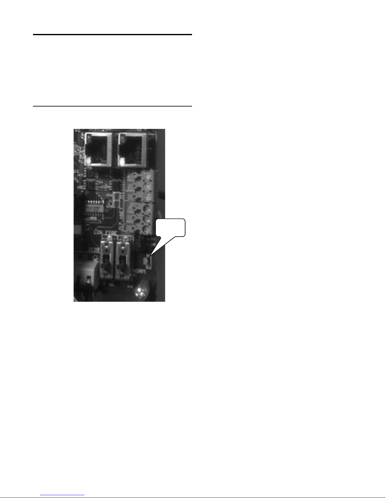
OPTIONAL FEATURES HeatNet Control REV 1.38-1
JPS1
Domestic Hot Water Methods
The HeatNet control supports Domestic Hot Water control
using (4) methods. When using the Domestic Hot Water
methods, the wire jumper, JPS1 on each control board
providing Domestic Hot Water, must be cut to limit the
boiler’s maximum output temperature of 200F. Refer to the
wiring Figures for control input and output locations.
Figure 24
Jumper JPS1
Jumper JPS1
temperature setting (DHW DIFF). Boilers are started as long
as the tank’s water temperature is below the (DHW
SETPOINT – DHW DIFF). The first boiler is started
immediately. The next boiler(s) is started after the ADD
BOILER DELAY time expires. Boilers are not added when
the temperature is above the (DHW SETPOINT – DHW
DIFF) and below the DHW SETPOINT. Once the DHW
SETPOINT is reached all boilers shut off. This limits the tank
temperature to the setpoint + post purge time of the DHW
pump.
Setting up this method is done via the menus in:
SETUP:DOMESTIC HOT WATER.
1. Connect a 10k thermistor from the DHW tank’s
sensor well to J10B terminals 1 & 2 on the DHW
MASTER, or stand alone boiler. Wire any pump
or valve from the DHW Pump relay (normally
open) contact to control flow of the heating water
into the tank’s coil.
2. Next, enter the DOMESTIC HOT WATER menu.
When prompted for DHW BOILER?, enter NO.
We will enter YES when we are finished entering
all parameters
3. Change the DHW SETPOINT to the desired
target temperature of the water in the tank. Once
the control determines there is a call for DHW,
the DHW SETPOINT is loaded and the Master
boiler will target this new setpoint.
The following Domestic Hot Water setup information will
include a walkthrough using the menus.
DHW METHOD 1: DHW Tank Sensor
Input
DHW METHOD 1a: DHW Heating ONLY using a
Single Boiler or a DHW MASTER and Member
boiler(s) employing H-Net
This method utilizes a 10k thermistor connected to the DHW
Sensor input of a DHW MASTER, or a stand alone boiler,
and a DHW tank WITHOUT a HEADER sensor. It requires a
DHW setpoint and other parameters to be set. This method is
used when the water temperature in the tank needs to be no
greater than the setpoint, with little overshoot of temperature.
One of its limitations is that it may short cycle. It functions
much in the same way a tank thermostat works.
This method works with (2) settings. A target tank water
setpoint (DHW SETPOINT) and a start/add boiler
4. Now, change the DHW DIFF to the desired
differential. This setting corresponds to the
minimum water temperature required in the tank.
DHW heating will be initiated when the DHW
tank’s water temperature is below the DHW
SETPOINT – DHW DIFF.
5. How long the temperature of the tank stays below
the (DHW SETPOINT – DHW DIFF) is used to
determine when boilers are started along with the
ADD BOILER DELAY.
6. Scroll down to USE SENSOR? Press the
SELECT key and select YES, then press the
SELECT key again. This will allow the boiler to
control the tank temperature using its sensor.
7. Press the DOWN arrow key again to position the
cursor beside the menu item DHW PRIORITY?.
Setting this value to YES will turn OFF the
system pump when the DHW mode is active.
Setting this value to NO leaves the system pump
on.
8. Press the DOWN arrow again and the menu item
POST PURGE should appear. This is the time
that the DHW pump relay remains energized after
the DHW SETPOINT has been satisfied. Once
the tank has reached setpoint all boilers will shut
off. Using the POST PURGE time to dump the
boiler’s heat into the tank may heat the tank
Page 28
Page 29

OPTIONAL FEATURES HeatNet Control REV 1.38-1
above the setpoint temperature. Care should be
taken here.
9. Press the DOWN arrow again and the menu item:
DHW MASTER?, will be displayed. If this item is
set to YES, once the DHW MASTER receives a
HEAT DEMAND signal, it will call other boilers
it has available using H-Net. Setting to NO,
requires no Heat Demand signal, and will only
enable the single boiler when the DHW Tank
Temperature drops below (DHW SETPOINT –
DHW DIFF).
DHW MASTER? YES is to be only be used
WITHOUT a Header Sensor
10. Finally, go to DHW BOILER?. Select YES. If
JPS1 has not been cut, a message will appear
instructing to do so. Once this is done, the stand
alone boiler will control the temperature in the
tank, or the DHW Master will control the
temperature in the tank using as many boilers as
it has available on H-Net.
DHW BOILER? Does not need to be set to
YES on MEMBER boilers, only the DHW
MASTER or on a stand alone boiler
providing DHW.
JPS1 MUST be cut on all boilers providing
DHW.
3. Change the DHW SETPOINT to the desired
target temperature of the water in the tank. Once
the control determines there is a call for DHW,
the DHW SETPOINT is loaded and the Master
boiler will target this new setpoint.
4. Now, change the DHW DIFF to the desired
differential. This setting corresponds to the
minimum water temperature required in the tank.
DHW heating will be initiated when the DHW
tank’s water temperature is below the DHW
SETPOINT – DHW DIFF.
5. Since the same the ADD BOILER DELAY time
is used for space heating and DHW, how long
the temperature of the tank stays below the
(DHW SETPOINT – DHW DIFF) has to be
considered when setting the ADD BOILER
DELAY.
6. Scroll down to USE SENSOR? Press the
SELECT key and select YES, then press the
SELECT key again. This will allow the boiler to
control the tank temperature using its sensor.
7. Press the DOWN arrow key again to position the
cursor beside the menu item DHW PRIORITY?.
Setting this value to YES will turn OFF the
system pump when the DHW mode is active.
Setting this value to NO leaves the system pump
on.
DHW METHOD 1b: Combo DHW and Space
Heating using a MASTER Boiler and Member
boiler(s) employing H-Net
This method utilizes a 10k thermistor connected to the DHW
Sensor input of a MASTER boiler, a DHW tank AND a
HEADER sensor. This Method works the same as DHW
METHOD 1a, but also has the ability to provide space
heating.
Setting up the DHW portion of this method is done via the
menus in: SETUP:DOMESTIC HOT WATER. For
information on setting up the space heating portion of the
method Refer to Heat Demand Control Method 1 located in
the CONTROL METHODS section on page 22.
1. Connect a 10k thermistor from the DHW tank’s
sensor well to J10B terminals 1 & 2 on the
MASTER, and connect a Header Sensor to the
SYSTEM HEADER input. Wire any pump or
valve from the DHW Pump relay (normally open)
contact to control flow of the heating water into
the tank’s coil.
2. Next, enter the DOMESTIC HOT WATER menu.
When prompted for DHW BOILER?, enter NO.
We will enter YES when we are finished entering
all parameters
8. Press the DOWN arrow again and the menu item
POST PURGE should appear. This is the time
that the DHW pump relay remains energized after
the DHW SETPOINT has been satisfied. If there
is no HEAT DEMAND signal, once the tank has
reached setpoint all boilers will shut off, and the
post purge time will begin. If there is a HEAT
DEMAND Signal when the tank has reached
setpoint, the boilers will continue running to
provide space heating, and the DHW pump relay
will be de-energized immediately. Using the
POST PURGE time to dump the boiler’s heat into
the tank may heat the tank above the setpoint
temperature. Care should be taken here.
9. Press the DOWN arrow again and the menu item:
DHW MASTER?, will be displayed. Set it to NO
for this DHW Method.
NOTE: This DHW Method requires no Heat
Demand signal to control the temperature in the
tank. As soon as the DHW Tank Temperature
drops below (DHW SETPOINT – DHW DIFF) a
boiler will be enabled.
NOTE: DHW MASTER? YES is only to be
used WITHOUT a Header Sensor. When both a
Header Sensor and a DHW Tank Sensor are
installed, because it has a HEADER Sensor, the
Boiler will recognize itself as a MASTER.
When DHW BOILER? is also set to YES, the
Page 29
Page 30

OPTIONAL FEATURES HeatNet Control REV 1.38-1
MASTER will automatically call on other boilers
when the DHW Tank Temperature drops below
(DHW SETPOINT – DHW DIFF) even when no
Heat Demand signal is present. However, the
MASTER will only enable boilers for space
heating in response to a Heat Demand signal.
10. Finally, go to DHW BOILER?. Select YES. If
JPS1 has not been cut, a message will appear
instructing to do so. Once this is done, the
MASTER boiler will control the temperature in
the tank using as many boilers as it has available
on H-Net.
DHW BOILER? Does not need to be set to
YES on MEMBER boilers, only the
MASTER boiler.
JPS1 MUST be cut on all boilers providing
DHW.
DHW METHOD 2: DHW Header
Sensor Input
1. This method will control a tank temperature when
the tank temperature setpoint needs to be
maintained for extended periods with minimal
cycling. Multiple boilers can be used via the HNet, as this method employs the same PID
algorithm as for space heating. For this method, a
tank temperature band needs to be tolerated.
JPS1 MUST be cut on all boilers providing DHW
to ensure the maximum output temperature of all
boiler is limited for DHW operation.
2. Use the Heat Demand Control Method 1
located in the CONTROL METHODS section on
page 22. Instead of placing the Header sensor in
the Header pipe, place it in a well in the tank.
The temperature at which boilers are staged ON,
and then OFF is controlled by the
SETUP:BOILERS:HEAT BAND differential.
This can be understood by referring to the
INTRODUCTION section on the MASTER in
the beginning of this manual.
This differential has the added effect of heating
the tank above the tank’s setpoint temperature. If
the tank setpoint is set to 140F and the heat band
is set to 10F, then the tank temperature will rise
to 145F before the first boiler turns off (setpoint
=140F +/-heat band/2). With (2) boilers running,
the SHED BOILER DELAY time could add to
the tank temperature. So, to ensure that all boilers
are shut off at the upper point of the heat band,
set the SHED BOILER DELAY time to 0. This
will effectively turn off all boilers at the upper
heat band point of: (example) 145F.
Now, there is one more thing to consider, the
pump’s post purge time. Dumping the heat from
all boilers (that were running) using a pump post
purge cycle will have an effect on the tank’s
water temperature. Consider this when
establishing the local pump’s POST PURGE
TIME.
3. Connect the Local Pump relay contact on J13 to
enable the DHW pump. Set its post purge time to
dump the boiler’s heat into the tank when the
boiler shuts off. Be aware that this may heat the
tank above the setpoint’s upper heat band
temperature.
4. Enable the system by placing the
LOCAL/REMOTE switch on the Master to the
LOCAL position.
DHW METHOD 3: Space Heating
with DHW Override
This method is for controlling DHW utilizing a tank
thermostat connected to a Master or Member boiler.
This method can be used instead of the 10k thermistor
sensor. When the thermostat contact closes across the
input OA OVR (J12A .7 & .8), the control will sense
this closure and enter the DHW heating mode.
In this mode, the boiler will fire to 100% and be
regulated by the OPERATE LIM setting located in
SETUP:SETPOINTS. The OP LIM BAND can be
used to keep the boiler from short cycling too much
by limiting the firing rate as it approaches the
OPERATE LIM.
1. Wire the dry contact from the thermostat on the
tank to the input on J12A terminal 7 & 8. Also, at
this time wire any pump or valve from the DHW
Pump relay (normally open) contact (J13
terminals 9, 10) to control flow of the heating
water into the tank’s coil.
2. Enter the DOMESTIC HOT WATER MENU.
When prompted for DHW BOILER?, enter NO.
We will enter YES when we are finished entering
all parameters
Follow the same steps as used to program the 10k
thermistor sensor method, but when asked to
USE SENSOR?, select NO.
Set the DHW MASTER to NO. A thermostat
can only control (1) boiler. H-Net is not available
with a thermostat on the tank.
Go to the DHW BOILER?, enter and select
YES. The Master or Member will now control
the temperature in the tank.
Page 30
Page 31
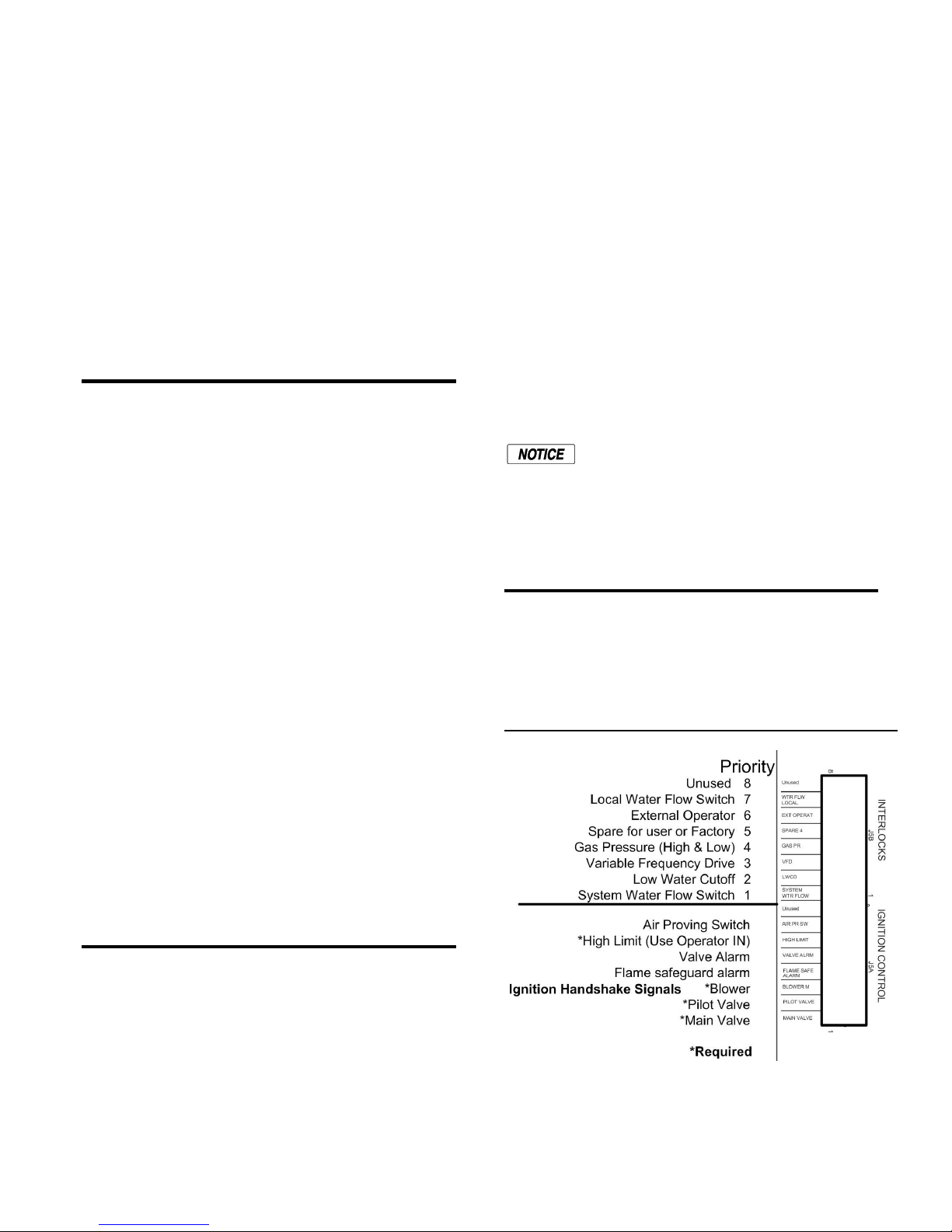
OPTIONAL FEATURES HeatNet Control REV 1.38-1
DHW METHOD 4: DHW using
Direct Control
The 4-20 mA input can be set to the HIGH(est) PRIORITY.
This can be set in menu: ADVANCED SETUP:4-20mA
INPUT. This allows a member boiler to be taken offline and
directly modulated by an external control.
If the Master is using it for heating and the 4-20mA is
set to HIGH PRIORITY, an external control can now
output a 4-20mA signal which will take over the
boiler’s fire rate and override all other heating
demand inputs. This is typically used for DHW
control.
Dual Fuel Option
The OPTION control input allows for optional functions. This
input designated as the ‘OPTION” input (J12B terminals 5 &
6) can be used as a programmed input. The menu:
ADVANCED SETTINGS:SYSTEM:OPTION,
can be used to set the DUAL FUEL option if equipped. It
assigns the K8 relay contacts on J4.1 &.2 to this function if
not using the Base Load Option.
The Dual Fuel option functionality is the same for a Master or
Member.
1. When the Option input switch is open, the Solid State
Relay (K8) has its contacts open on J4, between pins 1
and 2. FUEL 1
2. When the Option input is closed, the control detects a
change on this input and stops the boiler (if running).
3. Once the boiler stops, K8’s contacts close. This allows
the Fuel relay to energize and change the fuel. The
message FUEL CHNG will be displayed in the Status
Line. FUEL 2
4. If there is still a call for heat, the boiler restarts.
5. If the Option input now opens, the change is detected and
the cycle repeated.
A warning message appears when the Stack Temperature
exceeds 550F. The Alarm relay does not close and no
action is taken. The message is the only indication. Service
is usually required or needs to be scheduled (cleaning and
checkup).
An alarm message appears when the stack temperature
exceeds 700F. The alarm contact also closes to indicate a
problem with the boiler. The next thing that happens is the
boiler is limited to firing at ½ it’s called for rate. In
order to clear the alarm condition the Stack temperature
must fall below the warning temperature of 550F. This will
also remove the firing rate limit restriction.
A high Stack Temperature indicates that heat energy from
the combustion process is not being transferred efficiently
to the water. Overall boiler efficiency is reduced and
damage to the boiler could result. At this point action
should be taken immediately to correct the problem.
An additional function has also been included
to help protect the boiler. AUX
FUNCTIONS:HEAT EXCHANGER:LOW
TEMP HOLD is used to hold the boiler at the
low fire rate until the return temperature
exceeds the set value. The default is 130F, but
can be increased to 160F
Interlock Selection
The Smith HeatNet control allows selection of interlocks
to monitor. An interlock can be monitored by connecting a
wire from the point after the interlock to the appropriate
terminal on J5 of the control board.
Figure 25
Interlocks
Stack Temperature
The Smith HeatNet control monitors the stack temperature
and sets a warning or an alarm message in the event that
the Stack Temperature exceeds a predefined threshold. The
Stack Temperature is monitored since it is a good indicator
of the boilers health. The sensor that measures this
temperature is a 1k ohm RTD type sensor which can
handle the higher temperatures of the flue gas.
As an example: To connect the Local Water Flow switch to J5
first identify the normally open contact on the flow switch.
Next, attach a wire to this point. Now, run the wire through a
rigid conduit to the control and connect the wire to “J5B,
Page 31
Page 32

OPTIONAL FEATURES HeatNet Control REV 1.38-1
WTR FLW LOCAL”. Push the black latching lever on J5B
down to secure the wire.
Now, go to the keypad and hold down the ESC key until the
menus appear (about 5 seconds). Using the arrow keys,
position the arrow next to ADVANCED SETUP and press the
ENTER key. Now, using the DOWN arrow key, scroll down
until the SYSTEM menu appears. Press the ENTER key.
Again, press the ENTER key to enter the CONFIGURE
INTERLOCKS menu. Use the DOWN or UP arrow keys to
select LOCAL FLOW. Press the ENTER key to change the
setting to “ON” using the Arrow keys. The interlock is now
enabled and will detect and prove Local Water Flow. Press
the ESC key (4) times to return to the Main Screen.
If an interlock input is used it will be set to ON. If not used,
set it to OFF. When an interlock is not made and it is set to
ON, a message will be displayed along with a warning. The
boiler/system will not start or will stop running until the
interlock fault condition clears.
Firmware Loading
The HeatNet control supports a flash drive for loading
firmware. This is in addition to the loading of firmware
through the USB port.
Firmware versions can use either the flash drive port for
uploading, or the USB port along with a pc/laptop
computer.
Firmware files must be stored in a directory on the flash
drive in: \Firmware. The firmware files need to be placed
in this directory. As an example:
Once the files are placed on the flash drive, press and
hold the BACK key for 5 seconds to enter the Setup
menus. Select the ADVANCED SETUP: SYSTEM:
LOAD FIRMWARE. Select YES using the arrow
keys and press the SELECT key. Select YES when
asked, ARE YOU SURE?, and press the SELECT key.
When SOURCE is displayed, select USB DRIVE and
press the SELECT key. A message will be displayed to
ensure to REMOVE USB CABLE, if it is connected.
After the SELECT key is pressed, PLEASE WAIT…
will be displayed to check that the cable has been
removed.
Now, INSERT USB DRIVE will be displayed. Plug
the flash drive into J6. Press the SELECT key.
PLEASE WAIT… will be displayed as the control
reads the flash drive. The firmware file names will be
displayed on the top line. Cycle through the files on the
flash drive using the arrow keys. When the file to
download appears on the top line, press the SELECT
key to begin download/update.
The LOADING: xxxxxx message will appear and a
number will increment as the file is loaded. Once the
file finished loading, a series of beeps will acknowledge
this. Next, a chirping will be heard which indicates the
process of burning the new firmware code into the
control’s microcontroller. During this time the power
can not be lost/cycled or the firmware will become
corrupt. If this does occur, a laptop/pc will be required
to load the firmware via the USB port.
Once the new Firmware is loaded the ADVANCED
SETUP menu needs to be entered and then the LOAD
DEFAULTS menu. Select the FACTORY RESET and
select YES twice to load the factory defaults. The Flash
Drive does not automatically load the default settings as
the PC/Laptop loading does.
Page 32
Page 33
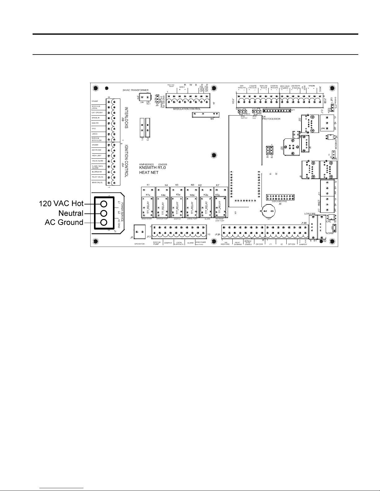
WIRING CONNECTIONS HeatNet Control REV 1.38-1
Wiring Connections
Figure 26
Power Connections
Page 33
Page 34
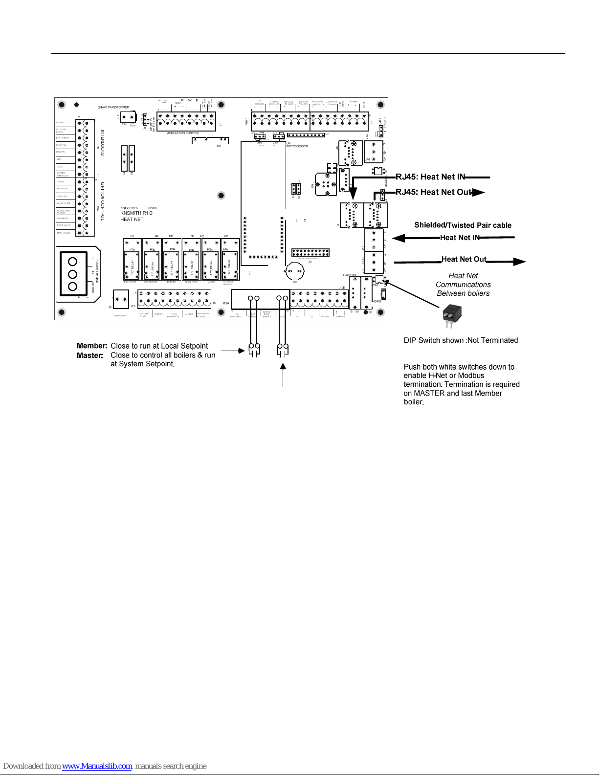
WIRING CONNECTIONS HeatNet Control REV 1.38-1
Figure 27
L
1
L
2
A
C
G
N
D
Heating Method 1 H-Net Master/Member
0
-
1
O
0
U
V
T
P
D
U
C
1
8
1
1
3
J
1
J
1
4
I
N
T
E
R
L
O
J
5
B
C
K
S
1
8
I
G
N
I
T
I
O
N
C
O
J
N
5
A
T
R
O
L
L
1
P
O
W
E
R
S
L
E
2
R
V
I
C
E
A
C
G
N
D
3
m
-
h
2
o
r
5
e
3
p
1
m
r
u
o
J
f
F
F
3
1
Y
A
L
E
R
_
7
7
T
Y
Y
A
A
L
L
E
E
R
R
_
_
7
7
7
7
T
T
T
Y
A
L
E
R
_
7
7
T
0
-
1
O
0
U
V
T
P
D
U
C
T
J
1
0
A
J
4
J
J
1
1
6
9
201
9
2
Y
Y
A
A
L
L
E
E
R
R
_
_
7
7
7
T
U
7
2
6
T
1
2
4
R
2
V
E
4
D
V
T
C
D
C
J
0
3
1
1
-
0
0
P
/
J
B
M
1
W
P
a
m
2
0
2
1
-
4
J
2
2
J
4
D
5
D
0
2
J
6
J
8
J
e
C
s
A
n
V
e
4
S
2
G
-
B
+
A
4
S
S
U
B
D
O
M
1
Y
1
2
J
2
J
G
-
B
+
1
A
1
J
1
G
T
E
N
-
H
B
+
7
1
A
J
3
S
1
S
P
J
Close this contact to override the Outdoor
Reset slope and run at the Domestic Hot
Water Setpoint.
The DHW Pump NO contact will also close.
Page 34
Page 35
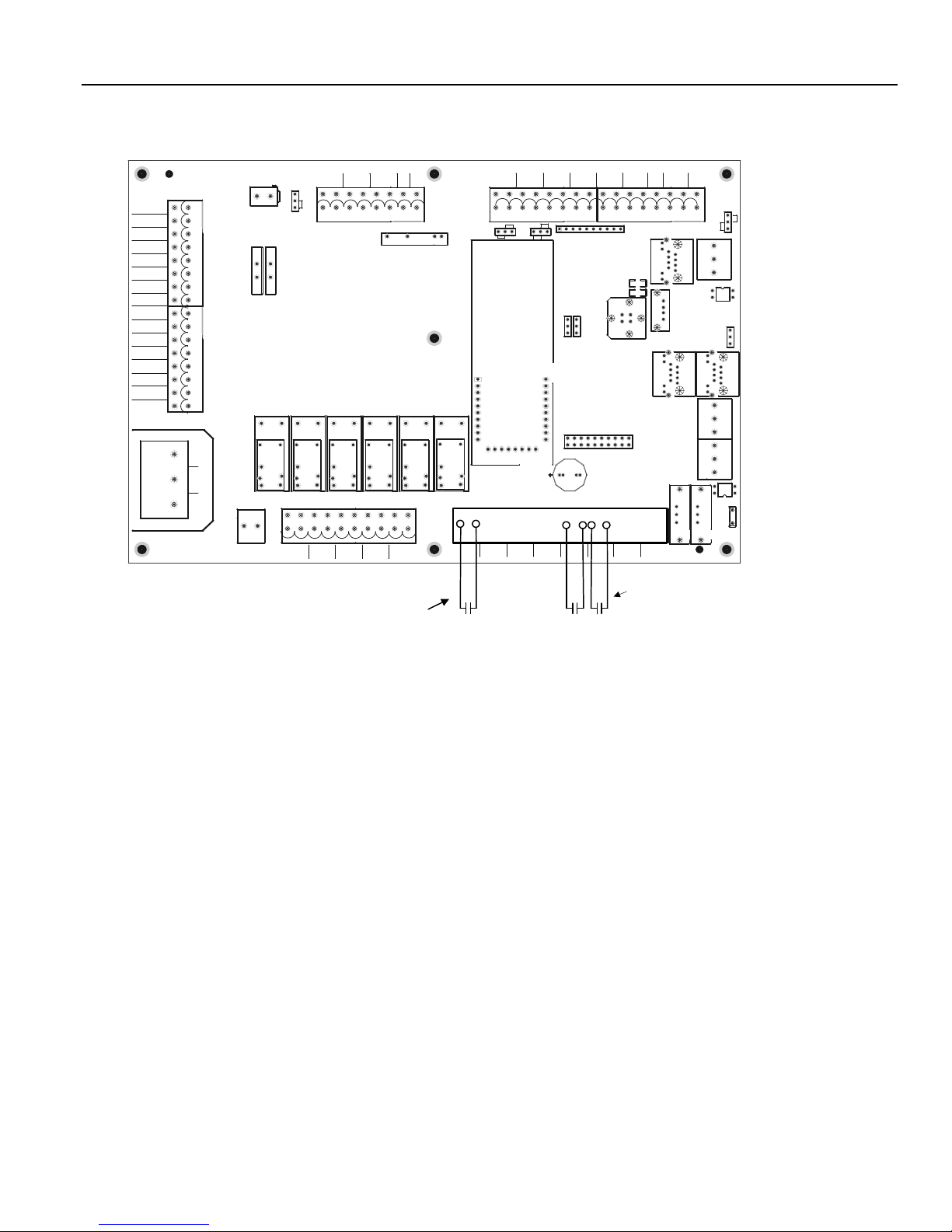
WIRING CONNECTIONS HeatNet Control REV 1.38-1
Figure 28
Unused
WTR FLW
LOCAL
EXT OPERAT
SPARE 4
GAS PR
VFD
LWCO
SYSTEM
WTR FLOW
Unused
AIR PR SW
HIGH LIMIT
VALVE ALRM
FLAME SAFE
ALARM
BLOWER M
PILOT VALVE
MAIN VALVE
L1
L2
AC GND
Heating Method 2 and 4: AA-High Fire and High/Low Master or Member Boiler
0-10VDC
8
1
1
3
8
L1
L2
AC GND
J1
24VAC TRANSFORMER
INTERLOCKS
1
IGNITION CONTROL
J5AJ5B
POWER SERVICE
1
J3
OPERATOR
HI/LO NO
1
J14
24V
24V
RET
F3
F1
KN/F-SERIES
KNSMITH R1.0
HEAT NET
K1
K1a
BOILR START
J13
1
1
2
3
J5
Jumper 2-3
for 135 ohm
02-2008
K4
K4a
T77_RELAY
T77_RELAY
1
SYSTEM
DAMPER
PUMP
Method 4
Close this contact to run
boiler at High Fire
1 AMP
4-20mA
+
MODULATION CONTROL
K5 K6
K5a
T77_RELAY
LOCAL
PUMP/VALVE
0-10VDC
OUTPUT
OUTPUT
W BR
-
J4
K8
K7
K2
K7a
K2a
K6a
T77_RELAY
T77_RELAY
T77_RELAY
DHW PUMP/
ALARM
AUX STATUS
Aux Status/
ALARMLOCAL PUMPDAMPERSYSTEM PUMP
DHW PUMP
10
J12A
AA
AA
AIR
WTR OUT OUTSIDE
-+-+
1
J10A
0-10
4-20ma
1
PWM/0-10
PWM
1
J18
J10
OUTPUT
VFD
U26
4-20mA/
HEAT
0-10v
DEMAND
ENABLEHIGH FIRE
WTR IN
U4
PROTOCESSOR
1
1
J16
J19
19
1
BZ1
8811
HEADER RETURN SUPPLY
SYSTEM
-+-+
20
2
DISPLAY/KEYPAD
DHW TANK
DAMPER
-
+-+
1
SIP1
J20
J9
T2T1OR OVR
OPTION
Method 2
Stage Control Inputs:
Stage 1, Stage 2
1 2
ALRM RST
SPARE 2
Sense
DAMPER
J22
D4
D5
RET
J8
J12B
24VDC
LOW FIRE
24VAC
+ -
4-20mA
24VDC
8
J10B
JP3
1
PWM/0-10
4-20ma
J12
G
JP4
A+ B-
S4
J6
S1
MODBUS
Y1
J21
J2
G
A+ B-
J11
1
G
HNET
A+ B-
J17
CAL
S3
JPS1
NORM
S2
Page 35
Page 36
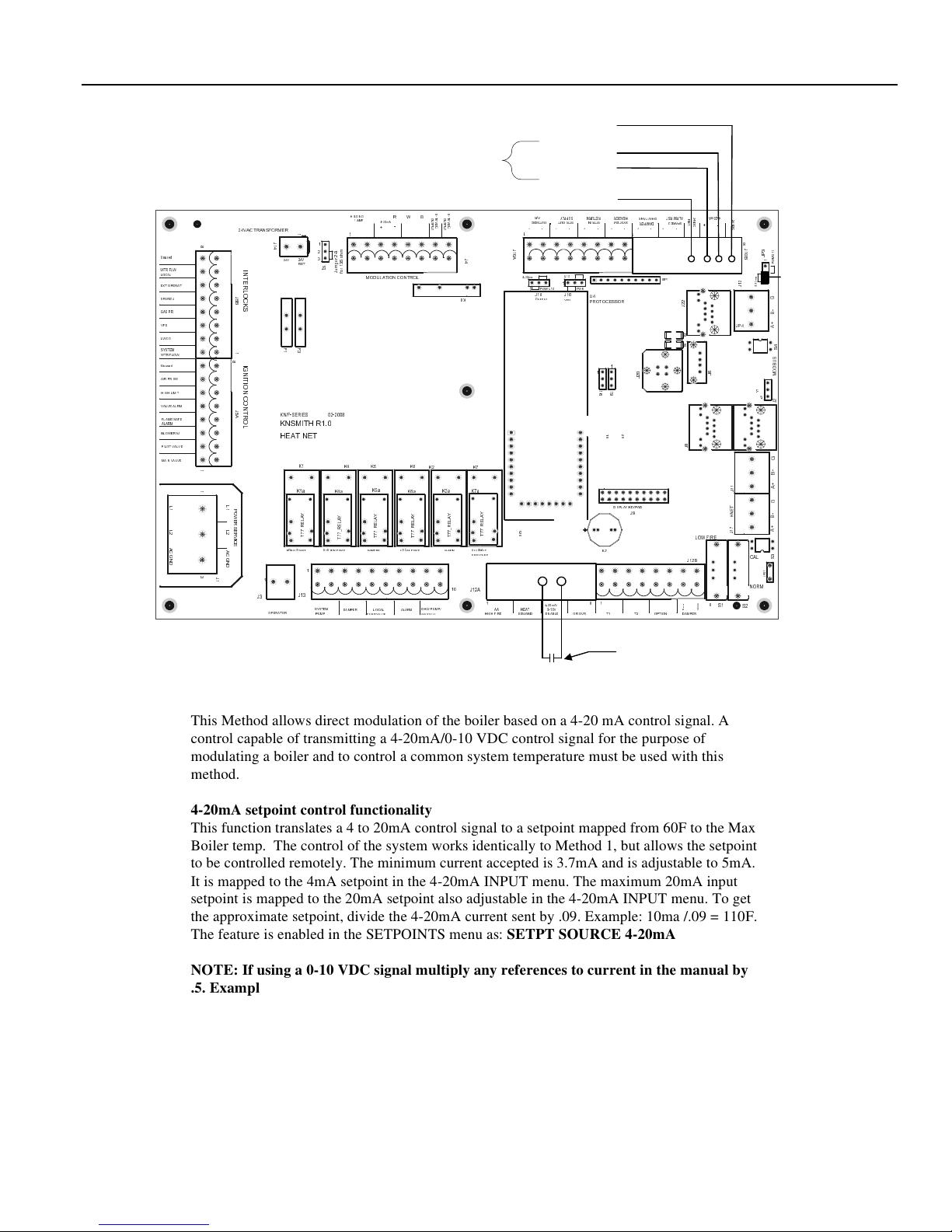
WIRING CONNECTIONS HeatNet Control REV 1.38-1
Figure 29
Heating Method 3 – 4-20mA
24 VDC
Unused
WTR FLW
LOCAL
EXT OPERAT
SPARE 4
GAS PR
VFD
LWCO
SYSTEM
WTR FLOW
Unused
AIR PR SW
HIGH LIMIT
VALVE ALRM
FLAME SAFE
ALARM
BLOWER M
PILOT VALVE
MAIN VALVE
L
1
L
2
A
C
G
N
D
J
1
0
A
Y
A
L
E
R
_
7
7
T
AA
4-20 mA/0-10 V DC 4-20mA/0-10 VDC +
24 VDC Return
AIR
WTR OUTOUTSIDE
-+-+
1
0-10
4-20ma
1
PWM/0-10
J18
OUTPUT
4-20mA/
ENABLEHIGH FIRE
PWM
J10
VFD
0-10v
DEMAND
1
U
2
6
HEAT
HEADERRETURNSUPPLY
SYSTEM
WTR IN
-+-+
1
U4
PROTOCESSOR
1
0
1
2
J
J
J
1
1
6
9
201
9
2
1
DISPLAY/KEYPAD
J9
BZ1
8811
T2T1OR OVR
Closing a contact
DAMPER
OPTION
ALRM RST
DHW TANK
+-+
SIP1
4-20mA
2
4
R
2
V
4
E
SPARE 2
D
V
T
C
D
+ -
8
J
LOW FIRE
C
A
V
4
2
C
8
J
0
1
3
1
-
0
P
0
/
B
J
M
1
W
P
Jumper in this
a
m
0
2
2
1
-
4
J
position: 4-20mA
G
-
B
+
JP4
A
4
S
S
U
B
D
6
J
S1
O
M
1
Y
1
2
J
2
J
G
-
B
+
1
A
1
J
1
G
T
E
N
-
H
B
+
7
1
A
J
3
CAL
S
1
S
P
J
NORM
S2
-
2
2
J
4
D
5
D
J12B
e
s
n
e
S
DAMPER
Modulation Control Input
0
0
-
HI/LO NO
1 AMP
4-20mA
3
m
-
h
2
o
r
5
e
3
p
1
m
r
u
o
J
f
K4
Y
A
L
E
R
_
7
7
T
DAMPER
1
MODULATION CONTROL
K5 K6
K5a
LOCAL
PUMP/VALVE
+
Y
A
L
E
R
_
7
7
T
24VAC TRANSFORMER
8
I
N
T
E
R
L
O
J
C
5
B
K
S
1
8
I
G
N
I
T
I
O
N
C
O
N
J
T
5
A
R
O
L
1
1
L
1
P
O
W
E
R
S
E
L
2
R
V
I
C
E
A
C
G
N
D
3
J
1
1
J3
OPERATOR
1
J
1
4
24V
24V
RET
F
F
3
1
KN/F-SERIES
KNSMITH R1.0
HEAT NET
K1
K1a
Y
A
L
E
R
_
7
7
T
BOILR START
1
J13
SYSTEM
PUMP
1
2
3
J5
02-2008
K4a
-
1
1
O
O
W BR
0
0
U
U
V
V
T
T
D
D
P
P
-
U
U
C
C
T
T
J
4
K8
K7
K2
K7a
K2a
K6a
Y
Y
A
A
L
L
E
E
R
R
_
_
7
7
7
7
T
T
DHW PUMP/
ALARM
AUX STATUS
Aux Status/
ALARMLOCAL PUMPDAMPERSYSTEM PUMP
DHW PUMP
10
J12A
here enables the
4-20mA control
signal input.
This Method allows direct modulation of the boiler based on a 4-20 mA control signal. A
control capable of transmitting a 4-20mA/0-10 VDC control signal for the purpose of
modulating a boiler and to control a common system temperature must be used with this
method.
4-20mA setpoint control functionality
This function translates a 4 to 20mA control signal to a setpoint mapped from 60F to the Max
Boiler temp. The control of the system works identically to Method 1, but allows the setpoint
to be controlled remotely. The minimum current accepted is 3.7mA and is adjustable to 5mA.
It is mapped to the 4mA setpoint in the 4-20mA INPUT menu. The maximum 20mA input
setpoint is mapped to the 20mA setpoint also adjustable in the 4-20mA INPUT menu. To get
the approximate setpoint, divide the 4-20mA current sent by .09. Example: 10ma /.09 = 110F.
The feature is enabled in the SETPOINTS menu as: SETPT SOURCE 4-20mA
NOTE: If using a 0-10 VDC signal multiply any references to current in the manual by
.5. Example: 5ma * .5 = 2.5 VDC
Page 36
Page 37
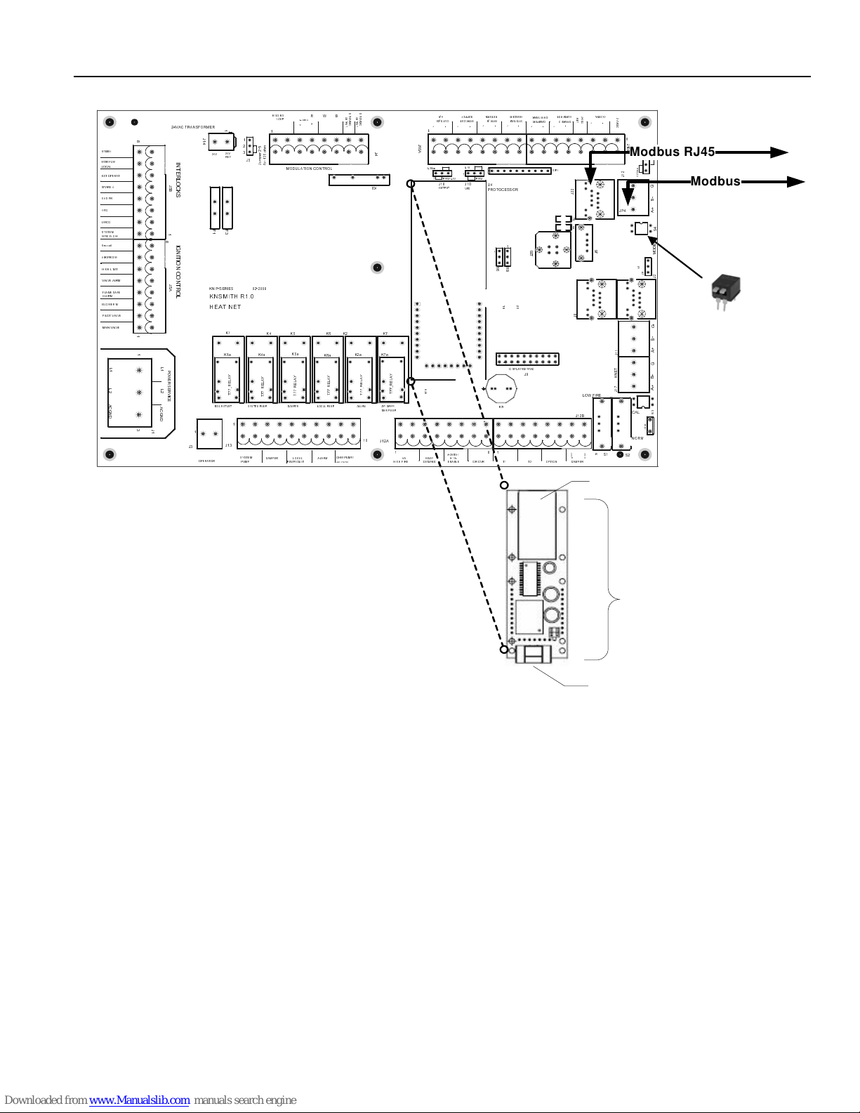
WIRING CONNECTIONS HeatNet Control REV 1.38-1
Figure 30
Unused
WTR FLW
LOCAL
EXT OPERAT
SPARE 4
GAS PR
VFD
LWCO
SYSTEM
WTR FLOW
Unused
AIR PR SW
HIGH LIMIT
VALVE ALRM
FLAME SAFE
ALARM
BLOWER M
PILOT VALVE
MAIN VALVE
L
1
L
2
A
C
G
N
D
Heating Method 5 MODBUS (Optional BACnet or LonWorks bridge)
0
0
-
-
1
HI/LO NO
1 AMP
4-20mA
3
m
-
h
2
o
r
5
e
3
p
1
m
r
u
o
J
f
K4
Y
A
L
E
R
_
7
7
T
DAMPER
1
MODULATION CONTR OL
PUMP/VALVE
+
K5 K6
K5a
Y
A
L
E
R
_
7
7
T
LOCAL
24VAC TRANSFORMER
8
I
N
T
E
R
L
O
J
C
5
B
K
S
1
8
I
G
N
I
T
I
O
N
C
O
N
T
J
5
R
A
O
L
1
1
L
1
P
O
W
E
R
S
E
L
R
2
V
I
C
E
A
C
G
N
D
3
J
1
1
J3
OPERATOR
1
J
1
4
24V
24V
RET
F
F
3
1
KN/F-SERIES
KNSMITH R1.0
HEAT NE T
K1
K1a
BOILR START
J13
1
2
3
J5
02-2008
K4a
Y
A
L
E
R
_
7
7
T
1
SYSTEM
PUMP
1
O
O
W BR
0
0
U
U
V
V
T
T
D
D
P
P
-
U
C
U
C
T
T
J
4
K8
K7
K2
K7a
K2a
K6a
Y
Y
Y
A
L
E
R
_
7
7
T
DHW PUMP/
ALARM
AUX STATUS
A
A
L
L
E
E
R
R
_
_
7
7
7
7
T
T
Aux Status/
ALARML OCAL PUMPDAMPERSYSTEM PUMP
DHW PUMP
10
J12A
AIR
WTR OUTOUTSIDE
WTR IN
-+-+
1
J
1
0
A
0-10
4-20ma
1
PWM/0-10
1
U
2
6
HEAT
AA
DEMAND
PWM
J18
J10
OUTPUT
U4
VFD
PROTOCESSOR
1
J
1
6
BZ1
8811
4-20mA/
0-10v
ENABLEHIGH FIRE
1
J
1
9
9
1
DISPLAY/KEYPAD
HEADERRETURNSUPPLY
SYSTEM
-+-+
1
201
2
J9
T2T1O R OVR
ALRM RST
DHW TANK
DAMPER
+-+
SIP1
0
2
J
OPTION
4-20mA
2
4
R
2
V
E
4
D
5
D
J12B
T
8
J
D
C
LOW FIRE
C
A
V
4
2
+ -
4
V
D
C
2
1
J
JP4
6
J
1
1
J
T
E
N
H
7
1
J
S1
8
J
1
0
3
1
0
-
P
0
B
/
J
M
1
W
Modbus RJ45
P
a
m
0
2
-
4
1
Y
1
2
J
1
CAL
1
S
P
J
NORM
S2
Modbus
G
-
Shielded or Twisted
B
+
pair w ire to Building
A
Managem ent Sys tem
4
S
S
U
B
D
O
M
2
J
G
DIP Switch shown :Not
-
B
Terminated
+
A
G
Push both white switches dow n to
-
B
enable B ACnet, Lonw orks, or
+
A
Modbus termination.
3
S
SPARE 2
-
2
2
J
e
s
n
e
S
DAMPER
RJ45 Configuration
and IP connection
NOTE: D o not plug th e Protocessor
There are pin headers located on the control (‘U’ s haped) that
the Protocessor bridge module plugs in directly. Align the
module in with po wer on o r
Protoces sor module may be d amaged .
sockets on the Protoc essor with the pin he aders on the
control, then press into place. All power for the bridge is
supplied by the version 2.x control. Co mm unication from the
Protocessor bridge to the H-N et control is also handled
through the socke ts.
Next, connect the BACnet or LonW ork s network cable to th e
Protocessor B ridg e Module Plug-in.
LonWorks or BACnet bridge w hich
Can be used instead of the
MODBUS input.
Protocessor module or configure the bridge using the
software tools. Once connected use the DIP switch to enable
termination.
Shieded or Twisted Pair
Connecti on (MSTP/
LonWorks)
Additional Bulletins and Instructions for Configuring BACnet or LonWorks are available on the website.
Page 37
Page 38
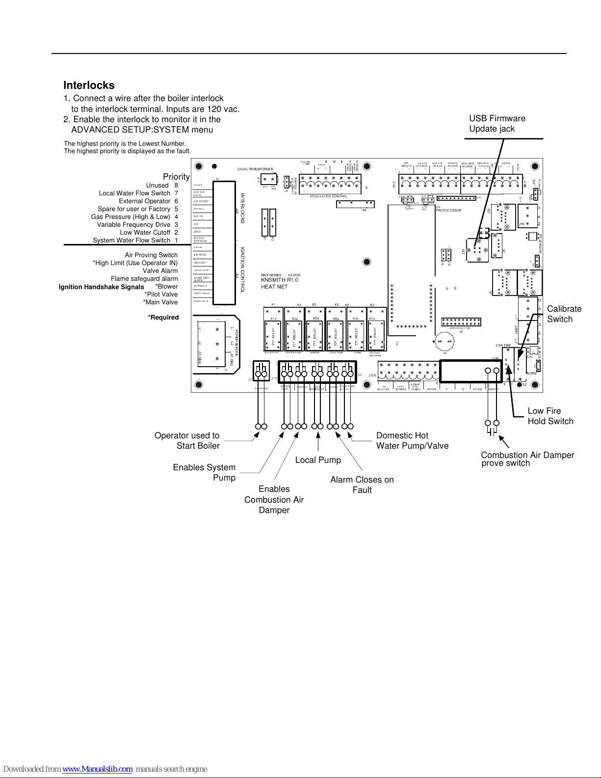
WIRING CONNECTIONS HeatNet Control REV 1.38-1
Figure 31
Interlocks
1. Connect a wire after the boiler interlock
to the interlock terminal. Inputs are 120 vac.
2. Enable the interlock to monitor it in the
ADVANCED SETUP:SYSTEM menu
The highest priority is the Lowest Number.
The highest priority is displayed as the fault.
Ignition Handshake Signals
Relays, Interlocks and Boiler Status
Priority
Unused
Local Water Flow Switch
External Operator
Spare for user or Factory
Gas Pressure (High & Low)
Variable Frequency Drive
Low Water Cutoff
System Water Flow Switch
*High Limit (Use Operator IN)
Air Proving Switch
Valve Alarm
Flame safeguard alarm
*Blower
*Pilot Valve
*Main Valve
*Required
Unused
8
WTR FLW
7
LOCAL
EXT OPERAT
6
SPARE 4
5
GAS PR
4
VFD
3
LWCO
2
SYSTEM
WTR FLOW
1
Unused
AIR PR SW
HIGH LIMIT
VALVE ALRM
FLAME SAFE
ALARM
BLOWER M
PILOT VALVE
MAIN VALVE
L
1
L
2
A
C
G
N
D
8
1
1
3
24VAC TRANSFORMER
J
5
B
1
8
J
5
A
L
1
P
O
W
E
R
L
S
2
E
R
V
I
C
A
E
C
G
N
D
J
1
I
N
T
E
R
L
O
C
K
S
I
G
N
I
T
I
O
N
C
O
N
T
R
O
L
J3
J
1
4
24V
F
1
KN/F-SERIES
KNSMITH R1.0
HEAT NET
K1a
BOILR START
1
OPERATOR
USB Firmware
Update jack
0
0
-
HI/LO NO
1 AMP
02-2008
3
m
-
h
2
o
r
5
e
3
p
1
m
r
u
o
J
f
K4
K4a
Y
A
L
E
R
_
7
7
T
DAMPER
4-20mA
1
MODULATION CONTROL
K5 K6
K5a
Y
A
L
E
R
_
7
7
T
LOCAL
PUMP/VALVE
1
1
2
3
24V
RET
J5
F
3
K1
Y
A
L
E
R
_
7
7
T
1
J13
SYSTEM
PUMP
-
W BR
O
1
O
1
0
0
U
U
V
V
T
T
+
-
P
P
D
D
U
U
C
C
T
T
J
4
K8
K7
K2
K7a
K2a
ALARM
K6a
Y
A
L
E
R
_
7
7
T
DHW PUMP/
AUX STATUS
Y
Y
A
A
L
L
E
E
R
R
_
_
7
7
7
7
T
T
Aux Status/
ALARMLOCAL PUMPDAMPERSYSTEM PUMP
DHW PUMP
10
J12A
AIR
WTR OUTOUTSIDE
-+-+
1
J
1
0
A
0-10
4-20ma
1
PWM/0-10
1
J18
J10
OUTPUT
VFD
U
2
6
4-20mA/
HEAT
AA
DEMAND
0-10v
ENABLEHIGH FIRE
PWM
U4
PROTOCESSOR
8811
WTR IN
1
J
1
6
1
J
1
9
9
1
DISPLAY/KEYPAD
BZ1
HEADERRETURNSUPPLY
SYSTEM
-+-+
201
2
J9
ALRM RST
4-20mA
2
DHW TANK
R
4
2
V
4
SPARE 2
E
DAMPER
D
V
T
+ -
C
2
2
J
4
D
5
D
8
J
J12B
e
s
n
e
S
DAMPER
LOW FIRE
C
A
V
4
2
D
C
8
0
J
1
3
-
1
0
P
/
0
J
M
B
W
1
P
a
m
2
0
2
1
-
4
J
G
-
B
+
JP4
A
4
S
S
U
B
D
6
J
S1
O
M
1
Y
1
2
J
2
J
G
-
B
Calibrate
+
1
A
1
J
T
E
N
H
7
1
J
Switch
1
G
-
B
+
A
3
CAL
S
1
S
P
J
NORM
S2
-
+-+
1
SIP1
0
2
J
T2T1OR OVR
OPTION
Low Fire
Hold Switch
Operator used to
Start Boiler
Enables System
Pump
Local Pump
Alarm Closes on
Enables
Domestic Hot
Water Pump/Valve
Combustion Air Damper
prove switch
Fault
Combustion Air
Damper
Page 38
Page 39
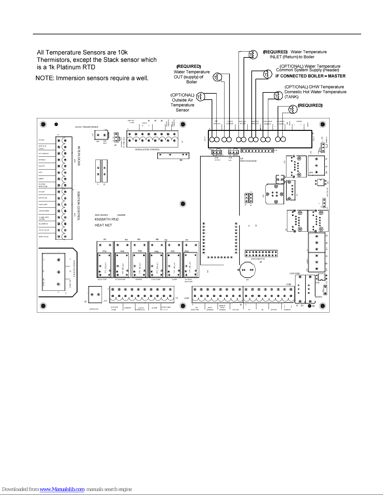
WIRING CONNECTIONS HeatNet Control REV 1.38-1
Figure 32
8
1
1
L
1
L
2
A
C
G
N
D
3
Temperature Sensors
1
J
1
4
I
N
T
E
R
L
O
J
C
5
B
K
S
F
F
3
1
8
I
G
N
I
T
I
O
N
C
O
N
T
J
5
R
A
O
L
L
1
P
O
W
E
R
S
E
L
R
2
V
I
C
E
A
C
G
N
D
J
1
1
Y
A
L
E
R
_
7
7
T
0
0
-
-
1
1
O
O
0
0
U
U
V
V
T
T
D
D
P
P
U
C
U
C
T
T
3
m
-
h
2
o
r
5
e
3
p
1
m
r
u
o
J
f
J
4
J
1
0
A
0
2
J
J
J
1
1
6
9
201
9
2
4
R
V
E
D
T
C
2
2
J
4
D
5
D
8
J
2
4
V
D
C
J
1
0
3
1
0
-
P
0
B
/
J
M
1
W
P
a
m
0
2
2
1
-
4
J
G
-
B
+
A
4
S
S
U
B
D
6
J
O
M
1
Y
1
2
J
2
J
G
-
B
1
1
2
1
Y
Y
Y
Y
Y
A
L
E
R
_
7
7
T
A
A
L
L
E
E
R
R
_
_
7
7
7
7
T
T
A
A
L
L
E
E
R
R
_
_
7
7
T
U
7
2
7
6
T
J
T
E
N
H
7
1
J
+
A
1
G
-
B
+
A
3
S
1
S
P
J
e
C
s
A
n
V
e
4
S
2
Page 39
Page 40
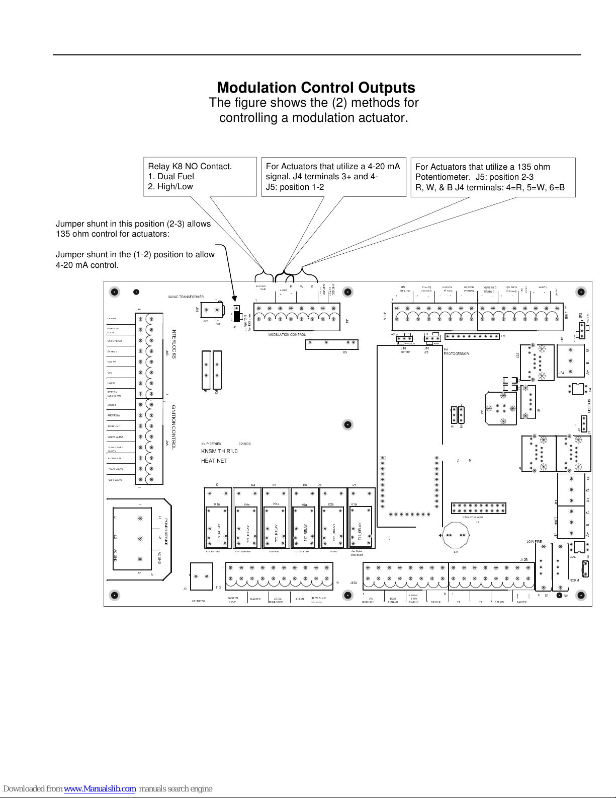
WIRING CONNECTIONS HeatNet Control REV 1.38-1
Figure 33
Controlling the Mod Motor
Modulation Control Outputs
The figure shows the (2) methods for
controlling a modulation actuator.
Relay K8 NO Contact.
1. Dual Fuel
2. High/Low
Jumper shunt in this position (2-3) allows
135 ohm control for actuators:
Jumper shunt in the (1-2) position to allow
4-20 mA control.
24VAC TRANSFORMER
J
1
4
I
N
T
E
R
L
O
C
K
S
I
G
N
I
T
I
O
N
C
O
N
T
R
O
L
24V
F
1
KN/F-SERIES
KNSMITH R1.0
HEAT NET
BOILR START
1
J3
OPERATOR
Unused
WTR FLW
LOCAL
EXT OPERAT
SPARE 4
GAS PR
VFD
LWCO
SYSTEM
WTR FLOW
Unused
AIR PR SW
HIGH LIMIT
VALVE ALRM
FLAME SAFE
ALARM
BLOWER M
PILOT VALVE
MAIN VALVE
L
2
A
C
G
N
D
8
J
5
B
1
8
J
5
A
1
1
L
1
L
1
P
O
W
E
R
S
E
L
R
2
V
I
C
E
A
C
G
N
D
3
J
1
For Actuators that utilize a 4-20 mA
signal. J4 terminals 3+ and 4J5: position 1-2
0
0
-
-
1
ALARM
1
O
O
W BR
K6a
Y
A
L
E
R
_
7
7
T
K2
DHW PUMP/
AUX STATUS
0
0
U
U
V
V
T
T
D
D
P
P
C
C
U
U
T
T
J
1
0
J
4
K8
K7
K7a
K2a
Y
A
L
E
R
_
7
7
T
Aux Status/
ALARMLOCAL PUMPDAMPERSYSTEM PUMP
DHW PUMP
10
J12A
A
Y
A
L
E
R
_
7
7
T
AA
HI/LO NO
1 AMP
4-20mA
+
1
24V
RET
F
3
K1
K1a
Y
A
L
E
R
_
7
7
T
1
J13
SYSTEM
PUMP
1
1
2
3
m
-
h
2
o
3
r
5
e
3
p
1
m
J5
r
u
o
J
f
02-2008
K4
K4a
Y
A
L
E
R
_
7
7
T
DAMPER
-
MODULATION CONTROL
K5 K6
K5a
Y
A
L
E
R
_
7
7
T
LOCAL
PUMP/VALVE
For Actuators that utilize a 135 ohm
Potentiometer. J5: position 2-3
R, W, & B J4 terminals: 4=R, 5=W, 6=B
U
2
6
HEAT
DEMAND
AIR
WTR OUTOUTSIDE
J18
OUTPUT
PWM/0-10
4-20mA/
ENABLEHIGH FIRE
-+-+
0-10
1
PWM
J10
U4
VFD
PROTOCESSOR
0-10v
8811
1
4-20ma
1
HEADERRETURNSUPPLY
DHW TANK
SYSTEM
WTR IN
1
1
J
J
1
1
6
9
9
1
DISPLAY/KEYPAD
BZ1
DAMPER
-+-+
+-+
1
SIP1
0
2
J
201
2
J9
T2T1OR OVR
OPTION
ALRM RST
4-20mA
2
4
R
V
E
SPARE 2
D
T
C
-
2
2
J
4
D
5
D
8
J
+ -
2
4
V
D
C
8
J
1
0
3
0
1
-
P
B
0
/
J
M
1
W
P
a
m
0
2
2
1
-
4
J
G
-
B
+
JP4
A
4
S
S
U
B
D
6
J
O
M
1
Y
1
2
J
2
J
G
-
B
+
A
1
G
-
B
+
A
3
CAL
S
1
S
P
J
NORM
S2
e
s
n
e
S
DAMPER
J12B
LOW FIRE
C
A
V
4
2
1
1
J
T
E
N
H
7
1
J
S1
Page 40
Page 41
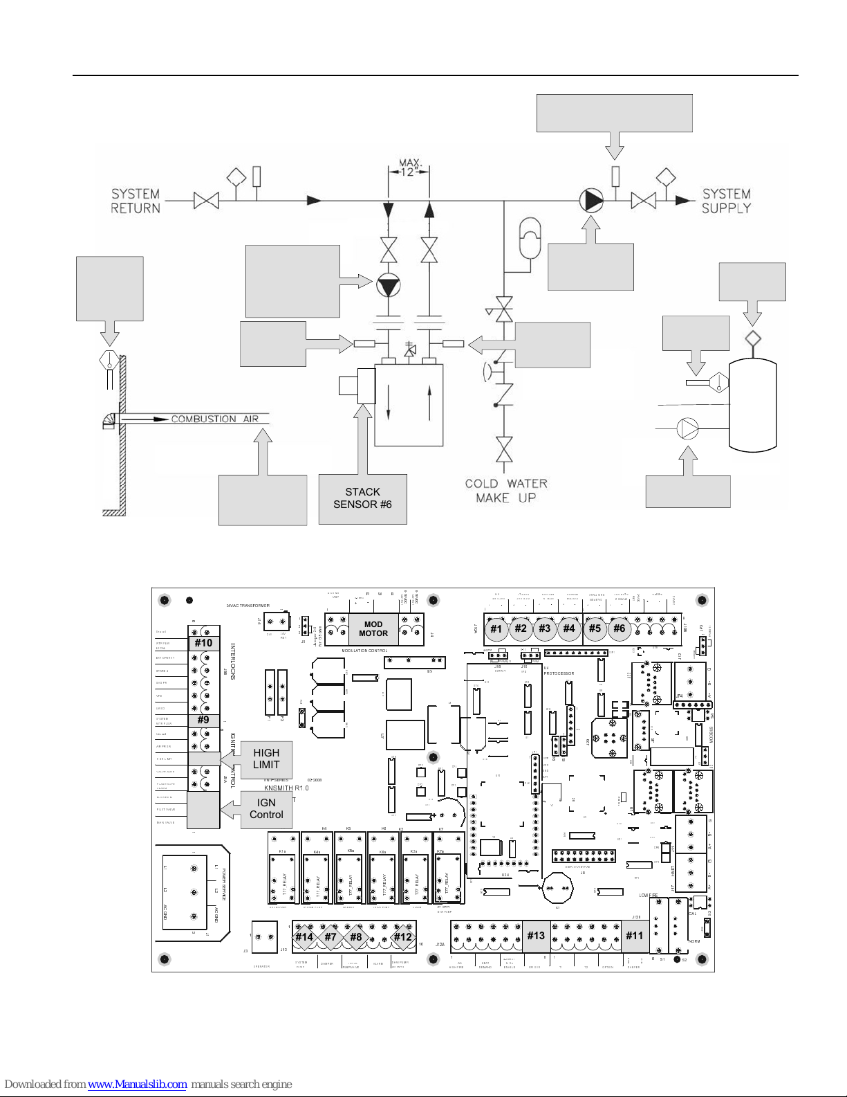
WIRING CONNECTIONS HeatNet Control REV 1.38-1
Figure 34
OUTDOOR
SENSOR
North Away
From Exhaust
#1
Typical Single Boiler System
LOCAL PUMP
ENABLE #8
FLOW PROVE
#10
RETURN
SENSOR
#3
COMBUSTION
AIR DAMPER
ENABLE #7
PROVE #11
STACK
SENSOR #6
BOILER
HEADER SENSOR
(Determines Master Boiler) #4
SYSTEM PUMP
ENABLE #14
FLOW PROVE #9
SUPPLY
SENSOR
#2
DHW RETURN
DHW SUPPLY
DHW TANK
AQUASTAT
#13
DHW TANK
SENSOR #5*
DHW TANK
DHW PUMP
ENABLE #12
0
0
-
Unused
WTR FLW
LOCAL
EXT OPERAT
SPARE 4
GAS PR
VFD
LWCO
SYSTEM
WTR FLOW
Unused
AIR PR SW
HIGH LIMIT
VALVE ALRM
FLAME SAFE
ALARM
BLOWER M
PILOT VALVE
MAIN VALVE
-
1
-
MOD
1
O
O
W BR
0
0
U
U
V
V
T
T
D
D
P
P
C
C
U
U
T
T
J
4
U16
U17
DHW PUMP/
AUX STATUS
K8
L1
CP1
CP4
RP2
CP2
CP3
C35
U13
K7
K2
K7a
K2a
Y
Y
A
A
L
L
E
E
R
R
_
_
7
7
7
7
T
T
Aux Status/
ALARMLOCAL PUMPDAMPERSYSTEM PUMP
DHW PUMP
10
J12A
U
2
4
1
1
U
U
7
K6a
Y
A
L
E
R
_
7
7
T
ALARM
HI/LO NO
1 AMP
4-20mA
24VAC TRANSFORMER
8
I
N
#10
T
E
R
L
O
C
J
5
K
B
S
1
#9
8
I
G
N
I
T
I
O
N
C
O
N
T
J
R
5
A
O
L
1
1
L
1
L
2
A
C
G
N
D
L
1
P
O
W
E
R
S
E
L
R
2
V
I
C
E
A
C
G
N
D
3
J
1
J
1
4
HIGH
LIMIT
IGN
Control
1
J3
OPERATOR
1
24V
24V
RET
F
F
3
1
KN/F-SERIES
KNSMITH R1.0
HEAT NET
K1
K1a
Y
A
L
E
R
_
7
7
T
BOILR START
1
#14
J13
SYSTEM
PUMP
1
2
3
J5
R
V
1
02-2008
K4a
+
1
3
m
-
h
2
o
r
e
p
m
u
J
5
3
1
r
o
f
K4
Y
A
L
E
R
_
7
7
T
MOTOR
MODULATION CONTROL
0
9
C
9
3
C
6
9
C
K5 K6
K5a
Y
A
L
E
R
_
7
7
T
#7 #8 #12
LOCAL
DAMPER
PUMP/VALVE
AIR
WTR OUTOUTSIDE
-+-+
1
J
1
0
A
#2 #3 #4 #5 #6
#1
0-10
4-20ma
1
PWM/0-10
1
U22
U14
C
9
7
U20
U
3
5
U
2
6
PWM
J18
J10
OUTPUT
VFD
U10
U2
U1
JP1
1
U15
CLK
Y2
U6
U34
WTR IN
U4
PROTOCESSOR
U18
1
1
J
J
1
1
6
VPP
9
VCC
GND
DAT
9
Y3
1
BZ1
U27
201
R
P
1
2
DISPLAY/KEY PAD
HEADERRETURNSUPPLY
SYSTEM
-+-+
1
1
JP2
U3
J9
#13
8811
4-20mA/
HEAT
AA
DEMAND
0-10v
ENABLEHIGH F IRE
T2T1OR OVR
ALRM RST
-
SPARE 2
2
2
J
4
D
5
D
U
3
2
J12B
#11
e
s
n
e
S
DAMPER
R
E
T
U
2
3
8
J
RP3
2
4
V
D
C
+ -
LOW FIRE
C
A
V
4
2
4-20mA
2
4
V
D
C
8
J
1
0
3
1
0
-
P
B
0
/
J
M
1
W
U19
P
a
m
0
2
2
1
-
4
J
G
-
B
+
JP4
A
4
0
3
U
6
J
U31
U33
CP6
CP5
S1
S
S
U
B
D
8
2
O
U
M
1
Y
1
2
J
2
J
G
-
B
+
1
A
1
J
1
G
T
E
N
-
H
B
+
7
A
1
J
3
CAL
S
1
S
P
J
NORM
S2
DHW TANK
DAMPER
+-+
SIP1
U8
U9
0
2
J
d
a
e
B
.
g
o
r
P
U12
U21
U
2
5
OPTION
Page 41
Page 42
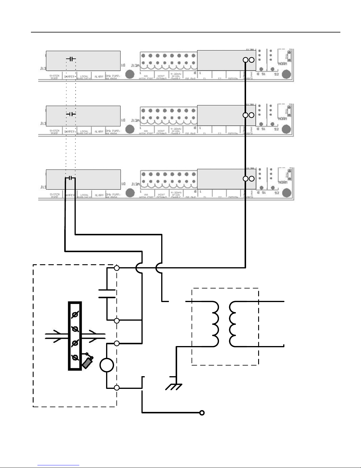
WIRING CONNECTIONS HeatNet Control REV 1.38-1
Figure 35
Common System Damper Wiring
MEMBER BOILER 2
Connection if Member
boiler is running as
Failsafe
DAMPER
Prove Switch
MEMBER BOILER 1
MASTER BOILER
NOTE: Ensure that the
Combustion Air Damper is enabled
on all Boilers for use.
SETUP MENU:AUX FUNCTIONS
24 VAC
DAMPER
DAMPER
Page 42
Enable
24 VAC Ret
Mains
DAMPER 24 VAC
Transformer
Connect to 24 VAC
Return on each Boiler
Page 43
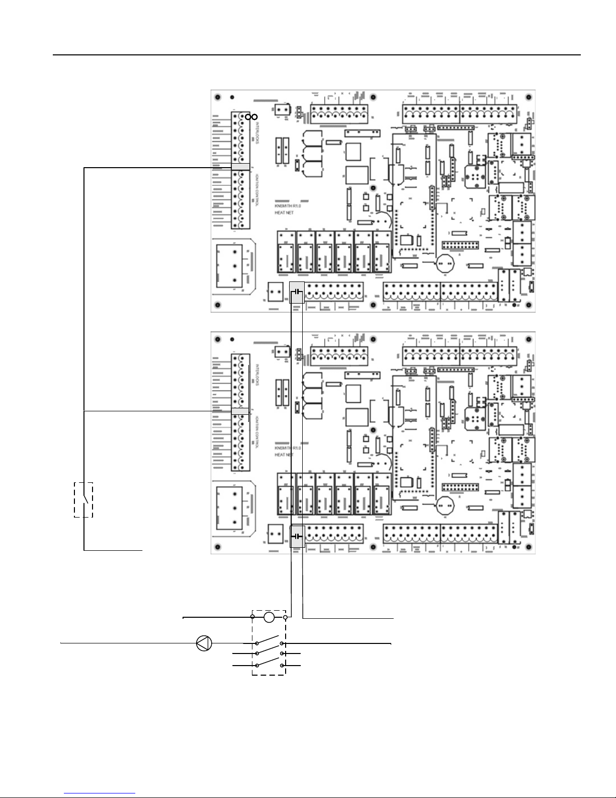
WIRING CONNECTIONS HeatNet Control REV 1.38-1
Figure 36
Failsafe Common System Pump Wiring
System Flow Prove
MEMBER BOILER 1
System Flow Prove
120VAC AFTER
FLOW SWTICH
System Flow
Prove Switch
120VAC
System Pump Voltage Return
120 Return
System Pump
MASTER BOILER
120VAC
System Pump Voltage Feed
Ph2
Ph3
System Pump
Contactor
Page 43
Page 44

CALIBRATION HeatNet Control REV 1.38-1
Calibration
A detailed startup and walkthrough of the calibration and HNet setup is provided in the Programming Examples
manual.
The calibration of the Smith-Series
boiler should only be performed by a
licensed technician.
To enter the calibration menus, place the S2 switch on the
main control board to the CAL position.
Be sure to set this switch back to NORM when the
calibration is complete, otherwise no external control inputs
will work (except T1-T2), the display will always indicate
CALIBRATE and some of the runtime temperatures will
not be displayed.
The MIN VFD setting, the MAX VFD setting, and the
Ignition setting can be adjusted in the calibration displays.
The values can be changed while running ONLY IN
MINIMUM FIRE (any, but only one of the T inputs
closed). Prior to ignition, the values may be changed, but
the blower will not operate.
Press the arrow keys until MIN VFD is shown in the
display, along with the minimum percentage value at
which the boiler is to run at min fire. While in Standby
(no call for heat on inputs), the minimum percent may be
preset. To set the minimum rate while running, any (1),
and only (1) of the (T) inputs must be closed in order to
set the boiler to MINIMUM fire. Press the ENTER key
for approximately 1 second. The Percentage value will
start flashing, indicating that it can be adjusted. Adjust
the Minimum value to the desired setting using the arrow
keys. The Minimum setting is clamped to its lowest rated
setting and cannot be adjusted below this. Once you are
done with this setting, press the ENTER key until the
value stops flashing. The new setting is now saved.
Page 44
Page 45

COMMUNICATIONS HeatNet Control REV 1.38-1
Log Entry
The Smith HeatNet control contains a log that records the
major activity (events) in the operation of the boiler. This
activity includes interlock faults, boiler starting and
stopping events, power cycles, misc. faults, and types of
calls-for-heat (control inputs). Setting the time clock to an
accurate time and date is very useful when events are
recorded, since the control will time stamp each snapshot. If
the system is configured to run with HeatNet, then only the
Master boilers SYSTEM TIME needs to be entered. The
Master will then set the time on all Member boilers.
The log is primarily used as a troubleshooting and
diagnostic tool, but may be used as a performance tool to
view run time cycles. Refer to the Control Pro Software on
the Smith website:
An event in time of the boiler’s state is presented via
multiple screens. Each screen event can be stepped through
using the arrow keys.
The top line displays the time and date the event occurred.
In the top right corner, the event # is displayed so that easy
indexing can be done using the arrow keys. The second line
displays the Water temperature of the boiler’s output
(supply) and the Setpoint temperature. The third line
displays the Outside Air temperature, and the Modulation
%. The bottom line is used to record the control state of the
boiler.
Figure 37
http://www.Smithboiler.com/
Log Entry Display
The control state is defined as the Boiler(s) that is
running, the Circulator Pump state, and the ignition
condition (Main Valve, Pilot Valve, Blower, and the
Ignition alarm). The # of boilers that are displayed is
limited to 7 if the boiler is the MASTER. If boilers #8 and
up need to be viewed, the Boiler Control Pro software
will need to be used. The Last 2 characters on the fourth
line indicate the heating mode the control is in. The
modes are:
NC = No Call for Heat
HD = Heat Demand (MASTER and Local modulation
control using PID control, MASTER and
MEMBER)
RM = Remote Modulation from 4-20ma input
HF = High Fire from ALL T-inputs closed or the AA
input
1T = Low Fire from any 1 T-input closed (Low Fire
or High Fire)
2T = Mid Fire from any 2 T-inputs closed (Low fire or
High Fire)
OP = Option input Active
HT = H-Net Control using the Heat-Link
communications cable
The bottom line is also used to indicate an interlock or
limit that has tripped. It may also indicate a sensor that
has failed. When this occurs, the normal bottom line in
the display is not visible, and the sensor fault is displayed.
For details on messages that appear on the fourth line: See
Appendix B.
H2O 1 2 7 °F
Outside Air
Temperature
OA
Boiler 1 On
Boiler 2 On
Boiler 3 On
: 0 5 : 4 2 P
3
6 5 °F
- - - - - -
1
Boiler 7
P = Circulator Pump
S = System Pump
D = DHW Pump
M = Main Valve open
Time
Stamp
1 0 / 1 4
SET
MOD%
P
(Ver 2.x control )
P = Pilot Valve open
M
PB
Event
1 3
1 4 0 °F
5 7
H HD
H= Honeywell Alarm
B = Blower ON
number
Water Setpoint
Modulation PWM %
NC = No Call for Heat
HD = Heat Demand
RM = Remote Mod 4-20ma
HF,1T, 2T, 3T = T-inputs Fire Rates
HT = H-NET Control
Page 45
Page 46
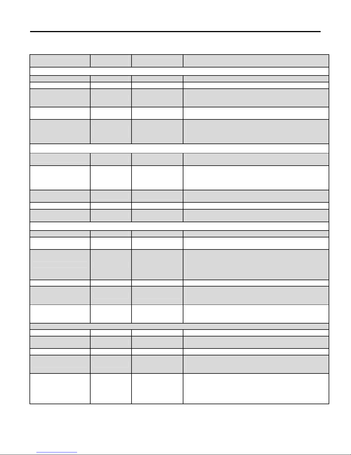
DEFAULT SETTINGS & MENU ITEM DESCRIPTIONS HeatNet Control REV 1.38-1
DEFAULT
DESCRIPTION
PUMP OPTIONS
Default Settings & Menu Item Descriptions — SETUP
MENU
VALUE
RANGE
BOILERS
# OF BOILERS 1 (1-16) If operating as a member.
LEAD BOILER # 0 (0-16) # of first boiler to run, determines the fire order in rotation. A
# of first boiler to run, determines the fire order in rotation. A
LEAD BOILER # 0 (0-16)
HEAT BAND
HNT M (M-16)
30 °F (2 -50°F)
0 disables the Lead Boiler function. Firing Mode determines
lead.
Differential temp around setpoint used to stage boiler(s)
OFF/ON
This line displays the boilers auto detected by H-Net. While
M is the Master boiler the numbers are the H-Net address of
each boiler from
2–16.
SETPOINTS
LOCAL SETPT
OPERATE LIMIT
LOCAL SETPT
OP LIM BAND
SETPT SOURCE AUTO
160 °F (40-220 °F)
215 °F (45-230 °F)
160 °F (40-220 °F)
20 °F (1-50°F)
AUTO
4-20mA
Local setpoint used to maintain temperature of SETPT
SOURCE
When running as a member, boiler shuts off when supply
temperature reached.
Boiler restarts at lower temp of OP LIM BAND or 10F
whichever is lower
Local setpoint used to maintain temperature of SETPT
SOURCE
Limits external input % when in (OP LIM - OP LIM BAND)
AUTO = Local/ System/ WWS Setpoint is used
4-20mA input is mapped to a setpoint.
OUTDOOR AIR RESET
OA RESET OFF Outdoor reset ratio (boiler water temp/outside air temp).
WARM WEATHER SD NO
WWS SETPOINT
SET OA SETPOINTS
WATER TEMP
At
HIGH OA TEMP
WATER TEMP
At
LOW OA TEMP
68 °F (40 – 100 °F)
140 °F (60 – 150 °F)
10 °F (-35 – 40 °F)
If set to YES, the boiler /system shuts down when the
temperature exceeds the WWS SETPOINT.
Temperature at which boiler shuts down, operation is below
this.
If boiler is running using either OA RESET or WWS and the
OA OVR input is closed the OA RESET slope is overridden
and runs at local setpoint until OA OVR input opens.
Boiler water temp setpoint when OA temp is at HIGH
OATEMP These four setpoints determine the OA reset
slope.
Header/Supply setpoint when OA Temp is at LOW OA TEMP
SYSTEM PUMP
POST PRGE TIME 2 minutes (2-60min)
ALWAYS ENABLED OFF ON/OFF ON = Pump never shuts off.
SUMMER PUMP JOG OFF
OVR ENAB IN WWS OFF ON/OFF
Page 46
ON/OFF
MON-SUN
Time in minutes to keep system circ. pump on after boiler
stops
Used with Outdoor Reset, Jogs pump for POST PRGE time
when system is in summer shutdown. Jog once a week
@12:00 AM.
Priority mode for the system pump while in Warm Weather
hutdown. ON: The system pump is allowed to run in WWS
when the OR OVR override input is closed. When set to
OFF, the system pump will not come on while in WWS with
the OR OVR override input closed.
Page 47

DEFAULT SETTINGS & MENU ITEM DESCRIPTIONS HeatNet Control REV 1.38-1
NIGHT SETBACK
OPTIONS
LOG/RUNTIME
LOCAL PUMP
DELTA TEMP ENAB OFF
DELTA TEMP 10 °F
POST PRGE TIME 2 minutes (1-60min) Time in minutes to keep local circ. pump on after boiler stops
ALWAYS ENABLED OFF Pump never shuts off.
PUMP/VALVE
OPTIONS
MASTER
PUMP/VALVE
REMAINS ON: OFF ON/OFF
LOCAL PUMP VFD OFF ON/OFF
FLOW PROVE 10s 10-240 sec
SETBACK ENTRY 1 (1 – 4) Four setbacks to adjust setpoint during a time period
ENTRY IS OFF Enable or disable the use of this setback
SETBACK
START DAY MON Day of the week to begin setback or a day range
TIME 12:00AM Time to begin setback
END DAY MON Day of the week to end the setback or a day range
TIME 12:00AM Time of the day to end the setback
20 °F (0 – 50 °F)
(2 - 50°F)
ON: Use Delta temperature to shut pump off when
temperature across boiler is less than DELTA TEMP setting.
ON: The master boiler will keep its pump/valve on when no
boilers are running. Prevents deadheading the system flow.
ON: Outputs a 0-10VDC or 4-20mA signal from J4 pins 1 & 5
that is proportional to the fire rate of the boiler. Connect to a
VFDcontrolling a Local pump.
This is an adjustable flow proving time to allow slower valves
to open before proving flow.
Temporarily subtracts this temp from the setpoint
TEMP SCALE
KEY CLICK ON Beeps when a key is pressed
SKIP PASSWORD ON Disables the Password
BRIGHTNESS 50% (25, 50,75,100)
RUN HOURS
DATA LOG ENTRY Displays the current entry in the data log
SIZE Displays the current size of the log in entries
BOILER CYCLES
°
F
(F or C) Fahrenheit scale is default
Four levels of display brightness, lower for longer life of the
display
Displays runtime hours. Total time the main valve has been
open.
Displays completed boiler cycles. Incremented when the
main valve turns OFF after it has been ON. Does not include
attempts to light.
Page 47
Page 48

DEFAULT SETTINGS & MENU ITEM DESCRIPTIONS HeatNet Control REV 1.38-1
AUX FUNCTIONS
COMBUST AIR
DAMPER
The LINKED/COMMON setting allows one common damper
to be used and controlled by the Master Boiler. All Member
boilers must
IN USE? YES
LINKED/COMMON
INDEPENDENT
have their damper prove inputs wired as per
Reference source not found., Error! Reference source
not found.
Section:
INDEPENDENT: Individual dampers are in controlled by their
respective boiler.
If set to YES, then OUTPUT RELAY K5 can be used to
control a combustion air damper. The Master can control a
common system damper or an individual damper. Members
control their respective damper independent of the Master.
Relay K5 is used to enable the combustion air damper. See
Error! Reference source not found., Error! Reference
source not found.
Needs to Prove the damper is open.
There are (2) inputs that may be used for the Combustion Air
INPUT:
PROOF TIME 2:00 (0 – 4min)
ALARM SILENCE
ALARM SILENCE IN
USE?
INPUT = J10B SPARE 2
FAILSAFE MODES
RUN IN LOCAL IF:
H-NET COMM LOST
LOW TEMP OFF
TEMP < 40F
J10B
DAMPER
YES
OFF
40 °F 35-200 °F
Damper. The first is located at J10B terminals 1 and 2
(legacy compatibility). The second input is located at J12B
terminals 7 and 8.
This is the proving time in minutes for the combustion air
damper prove switch. It is sensed at SPARE 1 on J10B or
J12B Pin 7. If J10B is used (legacy), Sensor #5 must be set
to ON/OFF in the sensors menu in order to detect the prove
switch being made. If the damper faults, a retry will occur
every 10 minutes in attempt to open the damper.
If Using J12B in a common damper configuration, wiring is
done beginning with the Master boiler. J12B Pins 7,8 are
connected to the prove switch of the combustion damper. Pin
8 is supplying 24 VAC and pin 7 is the sense input. A second
wire is connected to J12B pin 7 of the Master and the other
end connected to the first member boilers J12B pin 7. If
another member boiler is present, connect another wire to
the J12B Pin 7 terminal of the first member and the other end
to the second member boiler J12B pin 7. Continue this
method for each additional boiler.
This menu allows the configuration of the Alarm Silence
switch. It can be disabled so that the Alarm Silence switch
can not silence the alarm until the alarm is cleared; ALARM
SILENCE = NO. The default value is to enable the ALARM
SILENCE switch.
This setting allows the Alarm Switch to be looked at using
another input. This input should not be changed, but allows
for custom configurations to resolve conflicts.
If this entry is set to ON and the Member boiler does not see
any communications coming from the Master boiler, this
boiler will run in LOCAL. The boiler will continue to run in
LOCAL until communications is re-established or this entry is
set to OFF.
This entry may be set to one of the temperature sensors:
SUPPLY, HEADER, RETURN, or turned OFF (default). If
this entry is set to a sensor and the temperature falls below
TEMP, the boiler will automatically start and run the water
temperature up to the LOCAL Setpoint and then shut OFF.
This is the temperature that the selected sensor must fall
below for the boiler to start.
Error!
, page
Error! Bookmark not defined.
. Also see
Optional Features: Auxilliary Function Options
, page
Error! Bookmark not defined.
.
Page 48
Page 49

DEFAULT SETTINGS & MENU ITEM DESCRIPTIONS HeatNet Control REV 1.38-1
DEFAULT
DOMESTIC HOT WATER
SYSTEM CLOCK
MENU
HEAT EXCHANGER
ALARM TYPE: WARNING
EXCHR DELTA T
LIM-> HALF RATE YES
LOW TEMP HOLD
VALUE
40 °F
130 °F 130 – 160 °F
RANGE DESCRIPTION
This setting determines the way in which the control reacts
when the differential temperature across the heat exchanger
exceeds the specified maximum differential temperature. The
default alarm condition is a WARNING. The WARNING state
will allow the boiler to keep functioning and display a warning
message and a timestamp in the status screen when the
maximum differential temperature is exceeded. If FAULT is
selected, the boiler will shut down and act as if an interlock
has tripped. After the Delta T has dropped by 10F the boiler
will restart if the demand is still present.
This is the maximum differential temperature the heat
per Boiler
exchanger can see before the ALARM TYPE is applied. This
value can not be changed and is defined for each boiler size.
Limit to Half Rate: When set to YES, and the maximum
differential temperature (delta T) has been exceeded, the fire
rate called for is cut in half. In other words: if we are calling
for 80% modulation and have exceeded the delta T, the
boiler will only fire at 40%. The delta T needs to drop 10F
below the maximum delta T to reset this limit. The message “
½ INPUT” will be displayed on a member boiler and a Master
Boiler will display the Modulation % for the system even
though it is running at ½ of this rate. This method helps
protect the heat exchanger from damage due to excessive
delta T’s. If this Master boiler is running
The boiler will be held in low fire until the return temperature
exceeds the set value. The default is 130F, but can be
increased to 160F
DHW BOILER? NO
DHW SETPOINT
DHW DIFF
USE SENSOR? NO
DHW PRIORITY NO
POST PURGE 120s 0-600 secs
DHW MASTER? NO
TIME
DAY OF WEEK
MONTH
DAY
YEAR
PRESS SEL TO SAVE
160 °F 40 – 200 °F
5 °F 1- 30 °F
Setting this value to YES enables the Boiler/System for DHW
operation. DHW settings are only looked at if set to YES.
Setpoint that the boiler/system will target when a call for
DHW.
DHW SETPOINT – DHW DIFF : if DHW water temperature is
less than this temperature, the Boiler/System will enter DHW
Heating mode. Once the DHW SETPOINT is reached, DHW
mode is exited.
If this entry is set to YES, the DHW 10k Sensor is looked to
for controlling DHW water temperature. If set to NO, A
thermostat is used.
If the DHW PRIORITY is set to YES, then when there is a
call for DHW, the system pump shuts off. If NO, the system
pump stays on.
This is the time that the DHW relay remains on after the
DHW call ends.
This parameter can only be used if USE SENSOR? is set to
YES, and there is NO Header sensor Present..
If set to YES, this boiler becomes the DHW Master Boiler
and will use HeatNet to control member boilers based on the
DHW Sensor, DHW SETPOINT, and DHW DIFF. If set to
NO, only this boiler will run in DHW mode.
This time needs to be entered at first turn-on and inthe event
that power has been lost for more than 3 days. The time is
only required for an accurate log entry time-stamp and fault
time stamp.
The SEL key must be pressed after all time values have
been entered to save all time values at once.
Page 49
Page 50

DEFAULT SETTINGS & MENU ITEM DESCRIPTIONS HeatNet Control REV 1.38-1
DISTRIBUTED CTRL
This is no
MODULAR BOILER SET
Default Settings & Menu Item Descriptions — ADVANCED SETUP
CONTROL H-Net Displays method of operation: HeatNet (H-Net)
Auto detected, based on the HEADER sensor.
H-Net MASTER YES
H-NET ADDRESS 255 (2 –16) The local address is the address of a member device.
MODBUS ADDRESS 1 (1 – 247)
ADD BOILER DELAY 10mins (0 – 15min)
SHED BOILER DELAY 2mins (0-15min)
MODULATE DELAY
TIME
MOD MAX – LAST
FIRE
10 secs (0 – 60min)
70% (25 – 100%)
If the HEADER sensor is present and is set to TYPEZ, the
Smith-Series control is run as a H-Net MASTER (YES).
If the HEADER sensor is not TYPEZ, H-Net MASTER = NO.
The MODBUS address is for communicating with Laptop,
PC, or other MODBUS capable device. It is the 2nd
communication port reserved for host control.
This is the delay time in 30sec intervals, before starting a
new boiler. Boiler #1 is started immediately after a call for
heat. If a second boiler needs to start, the ADD BOILER
DELAY will need to expire before starting.
This is the delay time in 30 second intervals, before stopping
a boiler. A boiler is stopped immediately when the top of the
heat band is exceeded. If a second boiler needs to stop, the
SHEDBOILER DELAY will need to expire before stopping.
This is the time the boiler remains in min-fire before it
relinquishes control to the modulation % signal.
This value represents the maximum % of input on the boilers
if all the available boilers are not firing. Once all boilers are
firing, this clamp is removed and all boilers are allowed to
modulate up to 100%. When this value is limiting the input an
‘*’ is displayed and the “INPUT CLAMP” message is
displayed in the STATUS screen. This value is derived by:
multiplying twice the minimum fire rate of the boiler with the
least turndown (2* turndown(20% 5:1, 25% 4:1, 33% 3:1)). In
mixed boiler size configurations, more than (2) boilers in a
system, or when “bumps” in the temperature occur as boilers
are added and subtracted, this value may need adjustment.
The adjustments will help produce smooth temperature
control when each boiler is started and stopped. This method
ensures that, once a new boiler starts to fire, and holds its
fire rate at the minimum setting, it does not add its BTU
output to a boiler already firing at 100%. The boilers can not
be fired starting @ 0%, but start at a minimum (example:
20%) and introduce a minimum amount of BTUs into the
system. Section: SETUP & OPERATION
Page 50
Page 51

DEFAULT SETTINGS & MENU ITEM DESCRIPTIONS HeatNet Control REV 1.38-1
ADAPTIVE MOD
FIRING MODE
temperature band. It also minimizes temper
If MODulation MODE is set to ADAPTIVE on the Master
boiler, the Master lowers the system modulation rate of all
currently running boilers before a newly started boiler enters
the Main Valve state. Upon entering the Main Valve state of
MOD MODE ADAPTIVE
DROP DOWN ON CALL
DELAY RELEASE 0s
MODE TRUE
MIN RUNTIME 10 (1-255)
MIN OFF TIME 0 (0-10m)
PREDICT START: YES YES/NO
a newly fired boiler, the Master waits the DELAY RELEASE
time before allowing the PID to resume modulation control.
With MOD MODE set to ORIG KN, The Master boiler keeps
firing at the current modulation rate when a new boiler is
added and lets the PID adjust modulation rate accordingly.
If drop down is set to ON PILOT and MOD MODE =
ADAPTIVE, and when a newly added boiler starts, the
system waits until it enters its PILOT state before bring the
system modulation down. This allows for the system to
prepare for the new energy that is to be introduced. If DROP
DOWN is set to immediately, the system modulation is
lowered as soon as the newly added boiler is called.
Once the Main Valve opens on the newly added boiler and
the MOD MODE = ADAPTIVE the Master waits this amount
of time before releasing the PID to control modulation. This
allows for the newly added boiler to accumulate some soak
time.
LOFO: Boilers are fired Last On, First Off starting with Lead
Boiler
FOFO: Boilers are fired First On, First Off
TRUE: Boilers are fired based on the runtime they report
back to the Master boiler. Boilers with the least runtime are
fired first and boilers with the most runtime are stopped first.
MIXED: Different types of boilers can be mixed in a system
and fired based on (2) Priority sets. Boilers are started and
stopped with in the Priority sets based on their runtime
hours.
When the firing rotation is based on runtime, this value
represents the interval in hours of runtime before rotation
occurs. Boiler to Boiler.
This is the time in minutes that the boiler must remain OFF
before it can be fired again.
YES: Predicts the boiler restart point in the heating band
while the temperature of the boiler is drifting down through
the band. The
purpose of this is to ensure the temperature remains in the
Page 51
Page 52
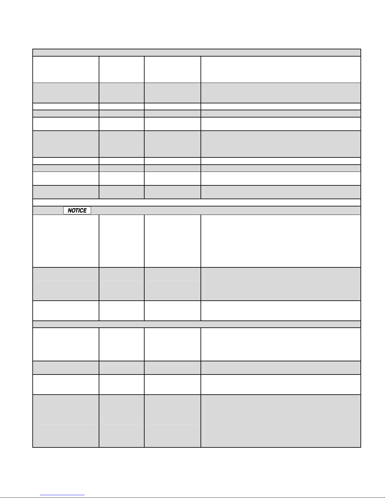
DEFAULT SETTINGS & MENU ITEM DESCRIPTIONS HeatNet Control REV 1.38-1
BASE LOAD BOILERS
SENSORS
4–20mA INPUT
This setting works in conjunction with the ADVANCED
BASE LOAD
BOILERS:
0 0-1
(START>MOD,
START >MOD
START<OA T,
START>RET)
START>MOD 100% (20–100) The base load relay K8 will close when the Modulation is >%.
START<OA T (40–140) The base load relay K8 will close when the OA temp is > T
START>RET (60–150F)
(FIRST,
STOP FIRST
STOP<MOD,
START>OA T,
START>RET)
STOP<MOD 20% (20–100) 20% (20–100) The base load relay K8 will open when the Modulation is <%.
STOP>OA T (40–100F) The base load relay K8 will open when the OA temp is > T.
STOP<RET (60–150F)
DELAY TIME 0 (0–60 minutes)
SETUP: SYSTEM:OPTION setting BASE LOAD. Currently
only (1) base load boiler is supported using relay K8 on the
Version 2.x control.
Used in Conjunction with DELAY TIME.
The base load relay K8 will close when the Return temp is >
T.
The base load relay K8 will open when the Return temp is <
T.
This setting allows a wait time before firing the base load
boiler once the start condition is met.
Sensors can only be changed when there is no call for heat. The boiler must be in STANDBY.
SENSOR #
TYPE
CALIBRATE
4mA SETPOINT
20mA SETPOINT
50 °F 50-220 °F
220 °F 50-220 °F
BOILER START 4.11mA 3.71-5.0mA
PRIORITY NORMAL
The first (4) sensor #’s are reserved as: OUTSIDE AIR,
water SUPPLY outlet, water RETURN inlet, and system
HEADER temperature. If the HEADER sensor is used
(TYPEZ), that boiler performs the tasks of the MASTER
boiler. If the HEADER sensor is set to NONE, its function is
the MEMBER. The remaining (2) sensors perform as user
selections and provide functions such as: Combustion Air
Proving.
There are (4) sensor types:
NONE = do not use this sensor
TYPEZ = 10k thermistor
ON/OFF = 5 volts supplied out to detect a contact/switch
closure.
Placing a precision 10k (TYPEZ) precision resistor across
the sensor input selected allows calibration of the sensor
input.
When using 4-20mA setpoint control in
SETPOINTS:SETPOINT SOURCE. This is the temperature
when a 4ma signal is applied and is tied to the BOILER
START mA. The Setpoint will then be mapped from 4mA –
20mA and example default of: 50-220F
This is the setpoint temperature when a 20mA signal is
applied.
This is the current value which will start the boiler. There is a
.1mA hysteresis value. So if the Boiler starts at 4.11mA it
shuts off a 4.01mA.
If the Priority is set to NORMAL, the boiler responds to its
HEAT DEMAND inputs in the Priority that is outlined in the
Control Methods section. If the PRIORITY is set to
HIGHEST, The 4-20ma input responds at the highest Priority
level (same as the AA input). This method may be used by
an external control to override the HeatNet control and fire
the boiler using this external control (external control
override). This allows for complex DHW control systems.
Page 52
Page 53
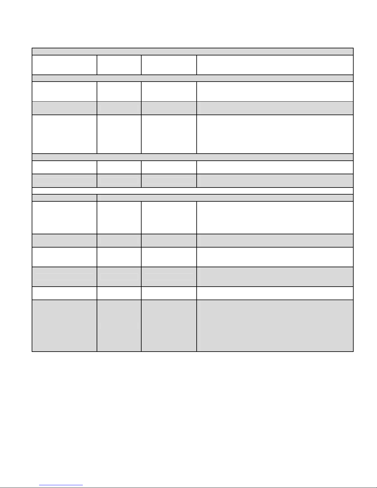
DEFAULT SETTINGS & MENU ITEM DESCRIPTIONS HeatNet Control REV 1.38-1
PASSWORD
COMMUNICATIONS
LOAD DEFAULTS
SYSTEM
Provides a limited access for security, though restoring
AAAAAA
system defaults will reset the password to the value
“AAAAAA”
1200, 2400,
BAUD 19200
DATA FORMAT 8E1
SETPOINT TIMER YES
FACTORY CAL?
FACTORY RESET? NO
BOILER TYPE
FIRING PRIORITY: 2 1 or 2
BTU IN 2000,000
CONDENSING YES
OIL DIRECT FIRE NO
LOAD FIRMWARE NO
OPTION: NO OPTION
4800, 9600,
19200, 38400
8E1, 8N1,
8N2, 8O1
NO OPTION
DUAL FUEL
BASE LOAD
This is the Baud rate for serial communication from the
MODBUS port. Selectable from 1200, 2400, 4800, 9600,
19200, 38400.
8 bits -Even Parity -1 stop bit, valid settings: 8E1, 8N1, 8N2,
8O1
If set to ‘YES”, the setpoint timer is enabled and requires a
periodic update of its value to keep from timing out and
retuning control to the
H-Net control. If set to “NO”, MODBUS always has control
and on a loss of MODBUS communications, H-Net does not
assume control.
Selecting YES will load just the factory calibration values:
MIN VFD, MAX VFD and IGN VFD.
Selecting YES will load all factory defaults except the
Calibration values, HeatNet, and Modbus addresses.
There are (2) Priority settings used by the MIXED boiler
rotation algorithm. Priority 2 is the default and lowest priority.
Priority 1 is the highest priority. A Priority may be assigned
to a set of boilers which fires and rotates based on time and
is independent of the other Priority set.
This is the BTU input rating of the boiler. This value is not
used with this version and is displayed only for reference.
This defines a boiler as condensing or non-condensing. This
value is not used with this version and is displayed only for
reference and future applications.
Selecting YES will skip the
sequence and display PRE PURGE until the
opens.
Answering YES deletes the existing Firmware and allows a
firmware update.
When set to DUAL FUEL, input T3/ RESERVED, OPTION
input is used to control the DUAL FUEL OPTION relay via K8
contacts on J4.2 &.6. When set to NO OPTION the input
T3/RESERVED, OPTION relay K8 on J4.2 &.6 is inactive.
When set to BASE LOAD, the Option Relay K8 on J4.2 &.6
is used as an enable contact for a base load boiler. The J4.1
&.5 0-10vdc/4-20mA output is used to modulate the base
load relay if it is of the modulating type.
PILOT
stage of the ignition
MAIN
valve
Page 53
Page 54

COMMUNICATIONS HeatNet Control REV 1.38-1
Figure 38
Description
Valid
in case of BMS failure. If the setpoint timer
MODBUS Communications
The Smith-Series control can be controlled using Modbus commands to Enable/Disable the boiler/system. A connection to
the Console Modbus Port on the Communications board is required. The Master Boiler assumes the role of MEMBER, RTU,
192Kb, 8 bits, Even Parity, 1 stop bit, when connected to a BMS (Building Management System).
The Member Boilers should not be connected to a BMS system other than to view Read Only addresses. Refer to
http://www.smithboiler.com/ website for greater detail on communicating with Modbus, BACnet, or LonWorks protocols.
MODBUS Input/Output Variables (Read/Write)
Address Name Raw Data Type Scale
Heat Demand/Request. Setting the state
40001 HeatDemand 1 bit unsigned ---
40002 SetpointTimer 16 bit unsigned ---
40003 Setpoint 8 bit unsigned 1.0
40004 OAResetEnable 1 bit unsigned --- Enables/Disables outdoor air reset mode.
member of this variable will put the boiler
in heating mode.
System Setpoint Timer
The system setpoint timer and system
setpoint work in tandem to externally
control (i.e. a BMS - building management
system) the operating setpoint. The
setpoint (countdown) timer should be
loaded with a timeout value (in seconds)
prior to writing the system setpoint. When
the timer reaches zero, the control
assumes that the BMS is no longer
operating and the local setpoint (saved on
the control) is reloaded. This is a failsafe
feature used to help safeguard the system
is not written, a default timeout value of 60
seconds is assumed.
System Setpoint (see
SetpointTimer
)
Values/Range
0 = no heat demand
1 = heat demand
0 – 65535 seconds
40 - 220 °F
0 = disabled
1 = enabled
40005 OARSetpoint 8 bit unsigned 1.0
40006 OARHighWaterTemp 8 bit unsigned 1.0
40007 OARHighAirTemp 8 bit unsigned 1.0 High outdoor air temperature setpoint. 50 – 90 °F
40008 OARLowWaterTemp
40009 OARLowAirTemp 8 bit signed 1.0 Low outdoor air temperature setpoint. -35 – 40 °F
40010 SetMonth 8 bit unsigned ---
40011 SetDay 8 bit unsigned ---
40012 SetYear 8 bit unsigned ---
Page 54
8 bit unsigned 1.0
Outdoor air reset setpoint. Temperature at
which boiler shuts down.
Boiler water temperature setpoint when
outdoor air temperature is at the high
outdoor air temperature setpoint
(OARHiAirTemp).
Header/Supply temperature setpoint when
outdoor air temperature is at the low
outdoor air temperature setpoint
(OARLoAirTemp).
Set real time clock – month (
Set real time clock – day (
Set real time clock – year (
see SetClock
see SetClock
see SetClock
)
)
40 – 100 °F
60 – 150 °F
70 – 220 °F
0 (January) - 11
)
(December)
1 – 31
0 – 99
Page 55
COMMUNICATIONS HeatNet Control REV 1.38-1
Figure 38
Description
Valid
Figure 39
R
aw Data
MODBUS Input/Output Variables (Read/Write)
Address Name Raw Data Type Scale
40013 SetHour 8 bit unsigned ---
40014 SetMinute 8 bit unsigned ---
40015 SetSecond 8 bit unsigned ---
40016 SetWeekday 8 bit unsigned ---
40017 SetClock 1 bit unsigned ---
Set real time clock – hour (
Set real time clock – minute (
Set real time clock – second (
SetClock
Set real time clock – weekday (
SetClock
Set (write) the real time clock.
Do Not Write more than once per minute
To write the real time clock, the system
variables (SetMonth, SetMonth, SetDay,
SetYear, SetHour, SetMinute, SetSecond,
SetWeekday) must first be loaded with the
correct date and time. Then, a 1 must be
written to the state portion of this system
variable to write the new date and time to
the system clock.
)
)
see SetClock
see SetClock
see
see
Values/Range
)
)
1 (Monday) - 7
0 = no action
1 = set/write the
0 – 23
0 – 59
0 – 59
(Sunday)
clock
MODBUS Input Variables (Read Only)
Address Name
30001 BoilersOn
30002 Modulation
30003 HeaderTemp
30004 SupplyTemp
30005 ReturnTemp
30006 OutsideTemp
30007 Spare1
30008 Spare2
30009 Month
30010 Day
30011 Year
30012 Hour
30013 Minute
30014 Second
30015 Weekday
30016 Boiler01Status1 16 bit --- Boiler (1 – 16) status flags. These See the “BoilerStatus1”
Type
8 bit
unsigned
8 bit
unsigned
16 bit
signed
16 bit
signed
16 bit
signed
16 bit
signed
16 bit
signed
16 bit
signed
8 bit
unsigned
8 bit
unsigned
8 bit
unsigned
8 bit
unsigned
8 bit
unsigned
8 bit
unsigned
8 bit
unsigned
Scale Description Valid Values/Range
The number of boilers currently
--running.
0.01 Current system modulation level. 0 – 100 %
0.01 Header / System temperature. 32 – 250 °F
0.01 Supply temperature. 32 – 250 °F
0.01 Return temperature. 32 – 250 °F
0.01 Outside air temperature. -40 – 250 °F
--- Raw A/D value from spare 1 input. -32768 to 32767
--- Raw A/D value from spare 2 input. -32768 to 32767
--- Real time clock month.
--- Real time clock day. 1 – 31
--- Real time clock year. 0 – 99
--- Real time clock hour. 0 – 23
--- Real time clock minute. 0 – 59
--Real time clock second. 0 – 59
--Real time clock weekday. 1 (Monday) – 7 (Sunday)
0 – 16
0 (January) - 11
(December)
Page 55
Page 56
COMMUNICATIONS HeatNet Control REV 1.38-1
Figure 39
R
aw Data
MODBUS Input Variables (Read Only)
Address Name
30017 Boiler01Status2 unsigned bits indicate the state of the
30018 Boiler02Status1
30019 Boiler02Status2
30020 Boiler03Status1
30021 Boiler03Status2
30022 Boiler04Status1
30023 Boiler04Status2
30024 Boiler05Status1
30025 Boiler05Status2
30026 Boiler06Status1
30027 Boiler06Status2
30028 Boiler07Status1
30029 Boiler07Status2
30030 Boiler08Status1
30031 Boiler08Status2
30032 Boiler09Status1
30033 Boiler09Status2
30034 Boiler10Status1
30035 Boiler10Status2
30036 Boiler11Status1
30037 Boiler11Status2
30038 Boiler12Status1
30039 Boiler12Status2
30040 Boiler13Status1
30041 Boiler13Status2
30042 Boiler14Status1
30043 Boiler14Status2
30044 Boiler15Status1
30045 Boiler15Status2
30046 Boiler16Status1
30047 Boiler16Status2
30048 Boiler01RuntimeHigh16
30049 Boiler01RuntimeLow16
30050 Boiler02RuntimeHigh16
30051 Boiler02RuntimeLow16
30052 Boiler03RuntimeHigh16
30053 Boiler03RuntimeLow16
30054 Boiler04RuntimeHigh16
30055 Boiler04RuntimeLow16
30056 Boiler05RuntimeHigh16
30057 Boiler05RuntimeLow16
30058 Boiler06RuntimeHigh16
30059 Boiler06RuntimeLow16
30060 Boiler07RuntimeHigh16
30061 Boiler07RuntimeLow16
30062 Boiler08RuntimeHigh16
30063 Boiler08RuntimeLow16
30064 Boiler09RuntimeHigh16
30065 Boiler09RuntimeLow16
30066 Boiler10RuntimeHigh16
30067 Boiler10RuntimeLow16
30068 Boiler11RuntimeHigh16
30069 Boiler11RuntimeLow16
30070 Boiler12RuntimeHigh16
30071 Boiler12RuntimeLow16
30072 Boiler13RuntimeHigh16
30073 Boiler13RuntimeLow16
30074 Boiler14RuntimeHigh16
Type
16 bit
unsigned
Scale Description Valid Values/Range
and “BoilerStatus2” Tables
24VAC interlocks, ignition circuit,
and various other conditions. See
the values column for a list of
conditions.
Boiler01 = Master
Boiler02 = Member01
…
Boiler16 = Member15
---
Boiler (1 – 16) Runtime seconds
High (Upper) and Low (Lower) 16
bit counters. To get the actual
runtime for any given boiler (##),
the high and low 16 bit counters
must be combined (concatenated)
into a single 32 bit counter as:
Boiler##RuntimeHigh16:Boiler##R
untimeLow16
Example
Boiler01Runtime =
(Boiler01RuntimeHigh16 * 65536)
+
Boiler01RuntimeLow16
Boiler01 = Master
Boiler02 = Member01
…
Boiler16 = Member15
0 – 4294967295 seconds
below.
Page 56
Page 57
COMMUNICATIONS HeatNet Control REV 1.38-1
Figure 39
R
aw Data
MODBUS Input Variables (Read Only)
Address Name
30075 Boiler14RuntimeLow16
30076 Boiler15RuntimeHigh16
30077 Boiler15RuntimeLow16
30078 Boiler16RuntimeHigh16
30079 Boiler16RuntimeLow16
30080 Boiler01Status3
30081 Boiler02Status3
30082 Boiler03Status3
30083 Boiler04Status3
30084 Boiler05Status3
30085 Boiler06Status3
30086 Boiler07Status3
30087 Boiler08Status3
30088 Boiler09Status3
30089 Boiler10Status3
30090 Boiler11Status3
30091 Boiler12Status3
30092 Boiler13Status3
30093 Boiler14Status3
30094 Boiler15Status3
30095 Boiler16Status3
30096 Boiler01SupplyTemp
30097 Boiler02SupplyTemp
30098 Boiler03SupplyTemp
30099 Boiler04SupplyTemp
30100 Boiler05SupplyTemp
30101 Boiler06SupplyTemp
30102 Boiler07SupplyTemp
30103 Boiler08SupplyTemp
30104 Boiler09SupplyTemp
30105 Boiler10SupplyTemp
30106 Boiler11SupplyTemp
30107 Boiler12SupplyTemp
30108 Boiler13SupplyTemp
30109 Boiler14SupplyTemp
30110 Boiler15SupplyTemp
30111 Boiler16SupplyTemp
30112 Boiler01ReturnTemp
30113 Boiler02ReturnTemp
30114 Boiler03ReturnTemp
30115 Boiler04ReturnTemp
30116 Boiler05ReturnTemp
30117 Boiler06ReturnTemp
30118 Boiler07ReturnTemp
30119 Boiler08ReturnTemp
30120 Boiler09ReturnTemp
30121 Boiler10ReturnTemp
30122 Boiler11ReturnTemp
30123 Boiler12ReturnTemp
30124 Boiler13ReturnTemp
30125 Boiler14ReturnTemp
30126 Boiler15ReturnTemp
30127 Boiler16ReturnTemp
30128 Boiler01CyclesHigh16
30129 Boiler01CyclesLow16
30130 Boiler02CyclesHigh16
30131 Boiler02CyclesLow16
30132 Boiler03CyclesHigh16
Type
16 bit
unsigned
16 bit
signed
16 bit
signed
16 bit
unsigned
Scale Description Valid Values/Range
Boiler (1 – 16) stage control input
---
0.01
0.01
---
flags. These bits indicate the state
of the stage control inputs. See
the values column for a list of
conditions.
Boiler (1 – 16) supply temperature
(if available). See BoilerStatus2 to
determine if the sensor is present.
Boiler01 = Master
Boiler02 = Member01
…
Boiler16 = Member15
Boiler (1 – 16) return temperature
(if available). See BoilerStatus2 to
determine if the sensor is present.
Boiler01 = Master
Boiler02 = Member01
…
Boiler16 = Member15
Boiler (1 – 16) Cycles High
(Upper) and Low (Lower) 16 bit
counters. To get the actual cycle
count for any given boiler (##), the
high and low 16 bit counters must
See the “BoilerStatus3”
Table below.
32 – 250 °F
32 – 250 °F
0 – 4294967295
Page 57
Page 58
COMMUNICATIONS HeatNet Control REV 1.38-1
Figure 39
R
aw Data
Figure 40
Bit Description
Valid Values/Range
MODBUS Input Variables (Read Only)
Address Name
30133 Boiler03CyclesLow16 be combined (concatenated) into a
30134 Boiler04CyclesHigh16
30135 Boiler04CyclesLow16
30136 Boiler05CyclesHigh16
30137 Boiler05CyclesLow16
30138 Boiler06CyclesHigh16
30139 Boiler06CyclesLow16
30140 Boiler07CyclesHigh16
30141 Boiler07CyclesLow16
30142 Boiler08CyclesHigh16
30143 Boiler08CyclesLow16
30144 Boiler09CyclesHigh16
30145 Boiler09CyclesLow16
30146 Boiler10CyclesHigh16
30147 Boiler10CyclesLow16
30148 Boiler11CyclesHigh16
30149 Boiler11CyclesLow16
30150 Boiler12CyclesHigh16
30151 Boiler12CyclesLow16
30152 Boiler13CyclesHigh16
30153 Boiler13CyclesLow16
30154 Boiler14CyclesHigh16
30155 Boiler14CyclesLow16
30156 Boiler15CyclesHigh16
30157 Boiler15CyclesLow16
30158 Boiler16CyclesHigh16
30159 Boiler16CyclesLow16
Type
Scale Description Valid Values/Range
single 32 bit counter as:
Boiler##CyclesHigh16:Boiler##Cyc
lesLow16
Example
Boiler01Cycles =
(Boiler01CyclesHigh16 * 65536) +
Boiler01CyclesLow16
Boiler01 = Master
Boiler02 = Member01
…
Boiler16 = Member15
MODBUS — BoilerStatus Flags
0 Pilot Valve 0 = closed, 1 = open
1 Blower Running 0 = off, 1 = running
2 Ignition Alarm 0 = ok, 1 = alarm
3 Valve Alarm 0 = ok, 1 = alarm
4 High Limit 0 = ok, 1 = tripped
5 Air Prove Switch 0 = open, 1 = closed
6 RESERVED (FACTORY)
7 Software Operator 0 = off, 1 = on
8 Header Sensor not Detected 0 = detected, 1 = not detected
9 Supply Sensor not Detected 0 = detected, 1 = not detected
10 Return Sensor not Detected 0 = detected, 1 = not detected
11 Outside Sensor not Detected 0 = detected, 1 = not detected
12 System Pump 0 = off, 1 = on
13 Combustion Air Damper 0 = off, 1 = on
14 Master Boiler 0 = member, 1 = master
15 Boiler Detected (at this address) 0 = not detected, 1 = detected
Page 58
Page 59
COMMUNICATIONS HeatNet Control REV 1.38-1
Figure 41
Bit Description
Valid Values/Range
MODBUS — BoilerStatus2 Flags
0 Disabled 0 = enabled, 1 = disabled
1 Heat Demand 0 = no demand, 1 = demand (1)
2 Alarm 0 = ok, 1 = alarm
3 Failed 0 = ok, 1 = failed
4 Member Error 0 = ok, 1 = error
5 Boiler Running 0 = off, 1 = running
6 Pump Running 0 = off, 1 = running
7 Spare 3 Interlock 0 = open, 1 = closed
8 LWCO Interlock 0 = open, 1 = closed
9 VFD Interlock 0 = open, 1 = closed
10 Gas Prove Interlock 0 = open, 1 = closed
11 Spare 4 Interlock 0 = open, 1 = closed
12 Operator Interlock 0 = open, 1 = closed
13 Water Prove (Flow) Interlock 0 = open, 1 = closed
14 UV Sensor Air Prove Interlock 0 = open, 1 = closed
15 Main Valve 0 = closed, 1 = open
This BoilerStatus2 Heat Demand Flag is a combination of the Heat Demand input and the Modbus Heat Demand (40001).
Page 59
Page 60

COMMUNICATIONS HeatNet Control REV 1.38-1
Figure 42
Bit Bit Bit
MODBUS — BoilerStatus3 Flags
0 AA High Fire 0 = off, 1 = on
1 Heat Demand (Local Override) 0 = off, 1 = on (1)
2 4-20ma Remote Enable 0 = off, 1 = on
3 Outdoor Air Reset Override 0 = off, 1 = on
4 T1 0 = off, 1 = on
5 T2 0 = off, 1 = on
6 T3 0 = off, 1 = on
7 T4 0 = off, 1 = on
8 reserved for future use ---
9 reserved for future use ---
10 reserved for future use ---
11 reserved for future use ---
12 reserved for future use ---
13 reserved for future use ---
14 reserved for future use ---
15 reserved for future use ---
This BoilerStatus3 Heat Demand Flag is Heat Demand input. On member boilers, this indicates a “Local Override”.
Page 60
Page 61

TROUBLESHOOTING HeatNet Control REV 1.38-1
Troubleshooting
This section is included as an aide to help troubleshoot
problems with the setup and operation of the boiler. See
Appendix A for additional fault messages.
Situation:
Nothing happens when the power switch is turned
on.
1. Check For 120 VAC on the Service connector J1. Verify
the line power is connected as per wiring diagram. The
Power switch light (ON - Position) should illuminate if
this is wired correctly. If the light does not illuminate on
the power switch, ensure that J14 is connected to the main
board and the power switch.
2. If the Ignition Control is active, but the front panel display
is inactive check:
a. Cable and cable polarity from the control board to the
display.
b. J14 on control board. 120vac is routed from here to
the transformer. The transformer returns 24vac to
power the control.
c. Check for 120vac on the primary of the transformer
and 24vac on the secondary. If one of the 24vac
interlocks has been shorted to ground or the 24vac
output is low, the transformer may be damaged or a
24vac circuit may be miss-wired.
The H-Net control is equipped with resettable
fuses on the power input circuit. Wiring power
incorrectly to the unit will cause these fuses to
open. Once the incorrect wiring is corrected,
the fuses should reset themselves in less than 5
minutes.
Situation:
The display is displaying random characters or the
control keeps resetting.
There may exist a grounding problem with the controller or
one of the boilers, pumps, contactors or other devices
connected to it. If all grounding is correct, there may be an
issue with radiated or induced electrical noise (interference).
This may be caused by, arcing across a contactor's contacts
when starting a pump motor, or a large electrical load. It may
also be caused by, the ignition transformer being improperly
grounded, or the spark gap set incorrectly.
1. Attempt to identify the noise source:
2. What is the boiler/controller trying to do at the time of the
failure?
3. Is the boiler on the same circuit as the noise source? (the
boiler should have isolated power.)
4. Are shielded sensor wires used? (Ensure the shields are
grounded only at the boiler control end.)
5. Are any sensors or sensor wires located near a
transmitting antenna? (Move sensor)
Situation:
There are no heating boilers on.
1. Check the settings for WWS SETPOINT, WARM
WEATHER SHUTDOWN; if the outdoor air temperature
is above the WWS SETPOINT and WARM WEATHER
SHUTDOWN is set to YES, the circulator pump relay
will be locked out and the heating boilers will not fire.
Figure 10
f the water temperature is within the heating band around
the setpoint, boilers will not come on. The water
temperature must fall below the lower band limit to begin
firing boilers.
Situation:
You get the error message for the Combustion Air
Damper.
1. The prove switch for the combustion air damper is not
closing. Check to make sure the dampers are being
controlled by the output relay. Also check to make sure
the prove switch is wired and working properly.
2. If you are not using the combustion air damper then it
needs to be disabled in the AUX FUNCTIONS menu.
Situation:
Unable to change the # of Boilers in the BOILERS
menu.
1. In H-Net method, the Smith-Series control auto-detects
the boilers in the system and adjusts the # of boilers
accordingly.
2. Using H-NET, if the # of Boilers is not being adjusted
properly to the actual amount of boilers in the system,
check each boiler. There can only be (1) master boiler, but
there can be up to 15 member boilers. Currently, a total of
16 boilers in a system.
Page 61
Page 62

TROUBLESHOOTING HeatNet Control REV 1.38-1
Situation:
The boilers menu only indicates 1 boiler, but there
are member boilers connected and the amber light
blinks on all of the boilers communication’s jacks.
1. Ensure that the latest version of firmware is installed on
all boilers. All boilers in a system must have the same
firmware revision.
2. Ensure the proper termination is set on the Master and the
last Member boiler.
Situation:
You get the error message – WATER FLOW SWITCH
or WAITING FOR FLOW.
1. If the control does not sense a closed circuit at input
connection, WTR FLW. Check to make sure the circuit
for the circulator pump is correct, that the pump is being
energized, and that the flow prove switch is working
properly.
2. If there is no flow prove switch, the Local Flow interlock
can be disabled in the CONFIGURE INTERLKs menu.
Situation:
Only the MASTER boiler Fires, but the system has
many boilers and is using H-Net.
1. In order for the MASTER boiler to act as a MASTER, the
header sensor must be set to TYPEZ, and there must be a
header sensor present. At power-up, the header sensor is
auto detected. If the temperature of the header sensor at
power-up is greater than –25 °F and less than 240 °F it is
considered a valid sensor. The boiler will default to the
MEMBER mode if the temperature is not in this range
and can only be run locally or by external inputs.
a. If the LOAD FACTORY DEFAULTS has been used
to restore all the default settings, the header sensor
has been set to NONE. This needs to be set as stated
in 1, and the header sensor will need to be replaced or
the temperature brought into a valid range. A power
cycle of the boiler will detect the sensor if it is in the
range as stated in 1.).
b. The H-Net needs a communications cable daisy-
chained between boilers. Ensure that a good
connection is made on the communications board and
that the lights on the dual RJ45 jack flash (roughly
twice a second). The MASTER is the only one that
should flash with no communications cables plugged
in.
Situation:
H-Net boilers are detected but then lost and then
detected again etc...
1. The H-Net communications cable may be receiving
interference from the blower, ignition, or other form of
radiated electrical noise. Termination of the jumpers may
not be correct or there is more than one master.
a. Ensure that the termination jumpers are set on the
MASTER boiler and only the LAST MEMBER
boiler. All of the other member boilers should have
their termination jumpers in the non-terminated
position.
b. There may be (2) or more MASTER boilers. Ensure
that only one header sensor is present and connected
to the SYS/DHW input. There should be no wires or
sensors connected to the SYS/DHW input if the
boiler is operating as a member. This input is auto
detected and defines the boiler as a MASTER.
c. Ensure the cable to connect the H-Net is of a shielded
or twisted pair type. Shielding of the cable is
required.
Situation:
I am in CALIBRATE and I cannot fire the boiler to
adjust it.
1. Only one, but any one of the T1-T2 inputs can be
used to start the boiler. All other inputs are disabled.
This method prevents an external control or Building
Management System from trying to control the boiler
while it is offline and being calibrated. If the boiler is
being used as a staged boiler controlled by an
external control, the staged inputs need to be
disconnected before CALIBRATION, since more
than one of the T inputs may be closed by the
external control.
Situation:
You have forgotten the password.
1. As a last resort, you can turn the controller off, then
depress and hold the ESC key while turning it back on.
This will load the default password “AAAAAA”.
d. Minimize the electrical interference by routing the
communications cable away from electrical noise
sources, such as: Motors, ignition controls, contactors
etc…
Page 62
Situation:
Firmware update program starts to load, but then
stops, or does not load at all.
1. Check that the termination shunts J3 and J6 are not in the
termination setting. If they are, remove them temporarily
Page 63

TROUBLESHOOTING HeatNet Control REV 1.38-1
while updating. Restore them for proper communication
with a building management system.
2. Ensure that the USB driver for your PC/Laptop computer
is properly installed.
3. Disconnect BMS or Protocessor Module if connected.
Situation:
All HeatNet Boilers fire at the same time.
1. This is usually caused by the HeatNet addresses on the
Member boilers not being set. If the address on each
boiler is not set, then all boilers will have address = 2 by
default. When the Master boiler calls to fire boiler #2, all
boilers with address #2 will fire. Set each Member boiler
to a unique address from 2-16.
2. Check the ADD Boiler delay time to ensure it is at a
reasonable value. A setting of 0 will start all the boilers
at the same time.
Situation:
The boiler is showing that it is running at 45% and
there is no fire in the sight glass.
Limit/Operating Limit Band should not overlap the
heating band. This may occur when a building
management system is controlling the setpoint and is
setting the setpoint in the operating limit band.
3. Example: Setpoint set to 180F (by Building Management)
and the Operating Limit is set to 200F with a 20F
Operating Limit Band. When the boiler is trying to deliver
180F to the load it’s supply temperature would be a
minimum of 180F. The beginning of the Operating Limit
Band (looks at supply temp) would be 200F-20F = 180F.
Now, when the Master is trying to maintain setpoint at
180F, the boiler is trying to reduce input beginning at
180F at its supply sensor and as a result, fighting the
setpoint. The Operating Limit band needs to be reduced in
this case, while taking into account the Heat Band
differential.
Situation:
The Master boiler sees all of the Member boilers in
the system, but does not fire any of the Members.
1. If the Master modulates to 100% without firing a Member
boiler and the Member boilers are seen by the Master (in
menu SETUP:BOILERS), then the Member boilers are
sending back offline status to the Master.
1. The Boiler always shows it’s called for firing modulation
%. This is not an indication of what the boiler is actually
firing at. If the ignition control fails to receive a call to
fire (last interlock closed on terminal 6 of the ignition
control) the display will indicate the called for %. Check
if the ignition control is in standby, if so then the HeatNet
control has closed the Start contact on J5..10 (Limits) and
is waiting for the Blower relay to close on the ignition
control which is monitored on J5.3 of the HeatNet control.
Situation:
I can hear the blower ramping up and down and the
firing rate is changing, but the display indicates it is
running at the same modulation rate.
1. The Boiler always shows it’s called for firing modulation
%. This is not an indication of what the boiler is actually
firing at. In this case, the boiler is trying to meet the called
for modulation % which is displayed, but is unable to do
so. The boiler protects itself by looking at it’s supply
water temperature and the temperature is probably in the
Operating Limit Band. While in the operating limit band,
the HeatNet control limits the input of the boiler. The
boiler tries to deliver the most input it can in an attempt to
meet the called for modulation % without tripping the
operating limit.
2. If the boiler is constantly varying in blower speed and in
the operating limit band there may be not enough flow
through the boiler or the Operating Limit/Operating Limit
Band may be improperly set. The Operating
a. The Member boilers may have an alarm or error
condition which would be indicated by a blinking
boiler # in the Boilers Firing screen.
b. Ensure the HeatNet is set up properly: Amber lights
blink on HeatNet Jacks. Only one Master boiler.
c. If the Member boiler is in Local Mode then it also
would not be called and report unavailable to the
Master.
d. If the Local flow switch for the Local pump is wired
to the System flow switch input this would also
create an offline condition. The Member needs to
detect system flow or have a jumper across that
sensor input in order for the Member boiler to report
available status. The Local flow prove switch must be
wired to the Water Flow interlock sensor input.
Situation:
We are trying to use a 0-10VDC control signal, but
when we send it 10 VDC only 7 VDC is measured at
terminal
J10B 6 & 7.
1. The HeatNet control was designed to use a 4-20mA
control input. If a 0-10 VDC control signal is to be
used, it must supply at least 20mA. 0-10 VDC control
signals are not recommended due to line loss and the
ability of the control signal to reject noise. So, if
Page 63
Page 64

TROUBLESHOOTING HeatNet Control REV 1.38-1
using a 0-10 VDC control signal it must be able to
supply the 20mA.
Situation:
We are using a Building Management System (BMS)
to control the boilers. We can write the setpoints,
Situation:
We are using a BACnet or LonWorks bridge. We can
but they keep changing back to their “default”
values after approximately 60 seconds.
talk to the bridge, but all of the data is zero (0) or
invalid.
1. When using a BMS, the setpoint values work in
conjunction with the SETPOINT TIMER. The
This condition usually indicates that the bridge is not
communicating with the HeatNet control. When operating
properly, the bridge continuously reads data from the boiler on
the Modbus port into an internal buffer. When a BACnet or
LonWorks read request is received, the buffered values are
placed in a BACnet or LonWorks packet and sent. If the
bridge has never been able to successfully read data from the
control, all data points will have their default value which is
typically zero. In this situation, the control will also not
respond to write commands; for instance changing the
setpoint.
SETPOINT TIMER is a failsafe feature used to help
detect that a BMS is no longer working or communicating
with the control. The time must be regularly loaded with
a predetermined number of seconds (1 – 65535). Every
second this value will decremented. If it reaches zero, the
local (permanently saved) values for the setpoints will be
loaded. The concept is that periodically (or every time a
setpoint is written), the BMS must write this value. If the
value reaches zero (0), the HeatNet control assumes that
the BMS in no longer functional and “safe” operational
values for the setpoints will be restored. As an example,
if it is decided that the BMS will write the control every 5
1. The control’s MODBUS ADDRESS must be set to one
(1). This is set in the ADVANCED SETUP-
>DISTRIBUTED CONTROL menu.
minutes, you may decide to write 600 seconds (10
minutes) to the setpoint timer. If after 10 minutes (5
minutes longer than the normal write interval) the BMS
has not written the timer, the saved setpoint values will be
2. The control’s BAUD (rate) must be set to 19200 and the
restored.
DATA FORMAT must be set to 8E1 (8 data bits, even
parity, 1 stop bit). On older (legacy) versions of
firmware, the DATA FORMAT was called PARITY
which must be set to EVEN. These settings are set in the
ADVANCED SETUP->COMMUNICATIONS menu.
2. As a convenience, the SETPOINT TIMER is
automatically loaded with 60 seconds (if it has fallen
below 60) each time the setpoint is written. If you decide
to take advantage of this convenience, you would need to
write the setpoint periodically at less than 1 minute
3. Check the termination on the BMS/Modbus port. If the
intervals.
control is the first or last device on the Modbus RTU
network, it should be terminated. For the short cable runs
(for instance when using a BACnet or LonWorks bridge
on a Revision 1.x board), the termination should be in, but
usually doesn’t matter.
The SETPOINT TIMER failsafe feature can be disabled by
writing a zero (0) to the timer. The feature will automatically
revert back to the enabled state whenever the control is reset
or power cycled. The SETPOINT TIMER failsafe feature
can permanently disabled in the ADVANCED SETUP-
4. Check the wiring. The Modbus RTU (RS485)
>COMMUNICATIONS menu.
connections on the HeatNet control are A(+), B(-), and G
(ground). Some systems use opposite polarity; A(-), B(+).
Always use the polarity to determine the proper
connections. A ground wire must always be used and a
shielded twisted wire is STRONGLY suggested.
Page 64
Page 65
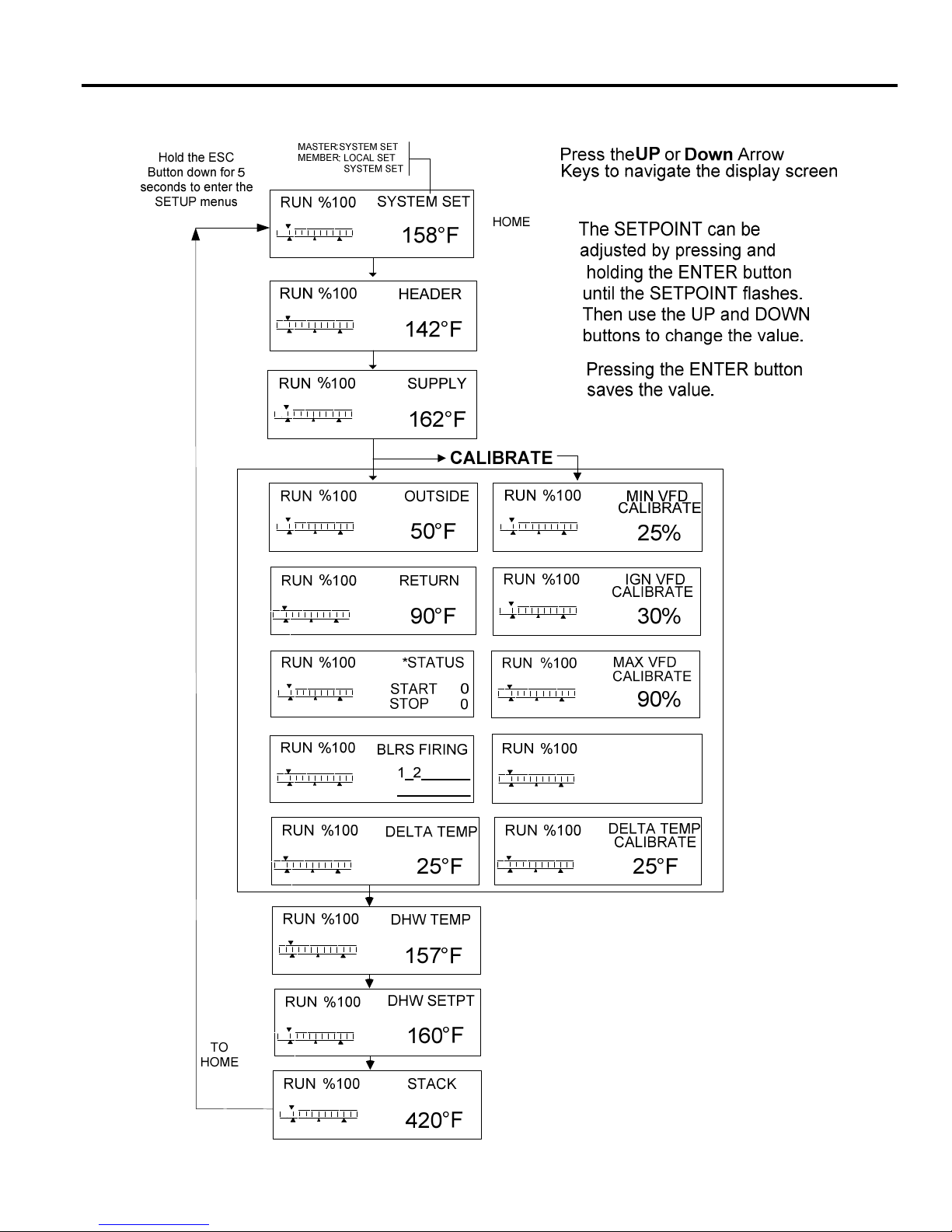
OPERATION HeatNet Control REV 1.38-1
Smith Series Run Screen
Page 65
Page 66
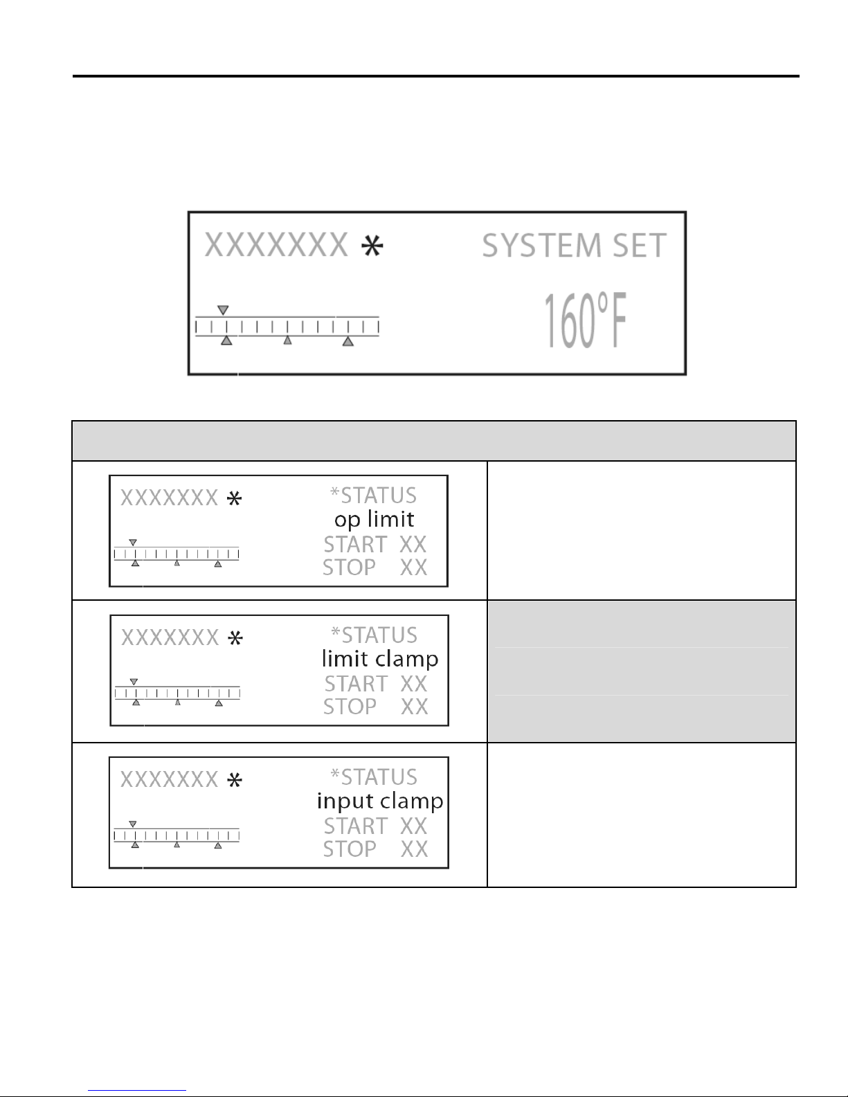
OPERATION HeatNet Control REV 1.38-1
* Status Information
Whenever an * is displayed on the RUN screen it indicates that there is more information available about the current running
conditions. This information can be viewed by going to the *STATUS screen as shown on the previous page. For more
information on the parameters discussed here please see the Default Settings & Menu Item Descriptions — SETUP, starting on
page 46.
Status information screens
This screen indicates that the boiler’s SUPPLY
Temperature has gone above the OPERATOR
LIMIT. This will mainly be seen on member
boilers to show why they are not available to
fire.
This screen indicates that the boiler’s SUPPLY
temperature has risen inside the OPERATOR
LIMIT BAND.
This screen indicates the boiler’s input is being
limited by the MOD-MAX value to optimize
system efficiency. This will only be seen on a
MASTER boiler.
Page 66
Page 67
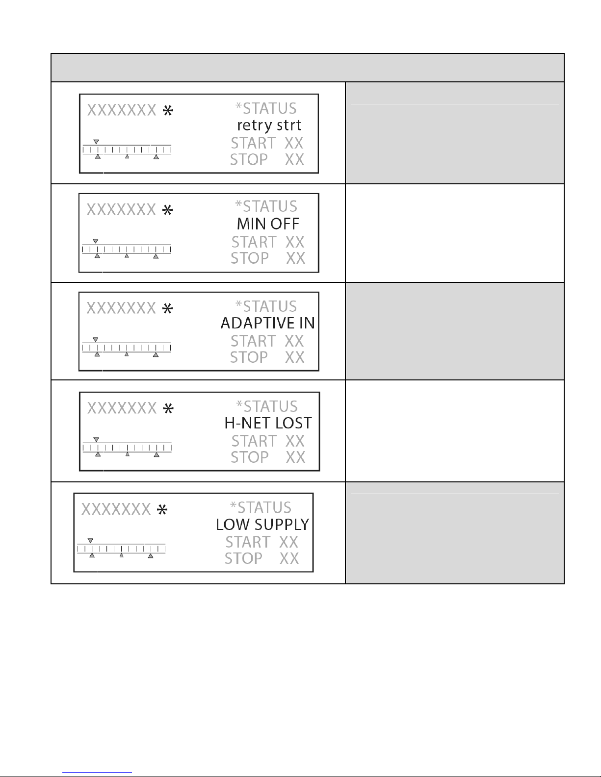
OPERATION HeatNet Control REV 1.38-1
Status information screens
This screen indicates the control is attempting
to re-initiate the ignition control because the
ignition control did not begin PRE-PURGE. For
more information see CALL SERVICE LOG
entry.
This screen indicates that the boiler’s has
received a heat demand, but it’s MINIMUM
OFF time has not expired.
This Screen indicates that the boiler’s input is
temporarily being limited to optimize the boiler’s
efficiency.
This screen indicates that the boiler is running
in LOCAL MODE because it has lost H-NET
communications with the MASTER, and the
failsafe mode has been activated.
This screen indicates that the boiler is running
In LOCAL MODE because the LOW
TEMPERATURE failsafe mode has been
activated. This particular screen shows that the
SUPPLY sensor was used, HEADER, or
RETURN sensors can also be used for this
failsafe mode.
Page 67
Page 68
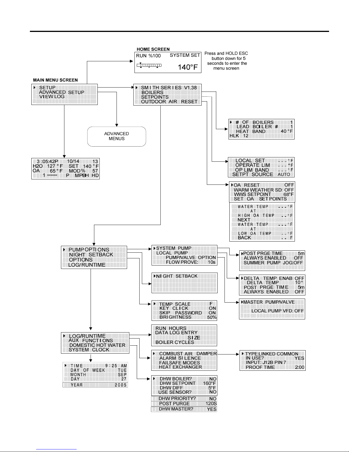
OPERATION HeatNet Control REV 1.38-1
Smith Series Menu Tree Version 1.38
Page 68
Page 69
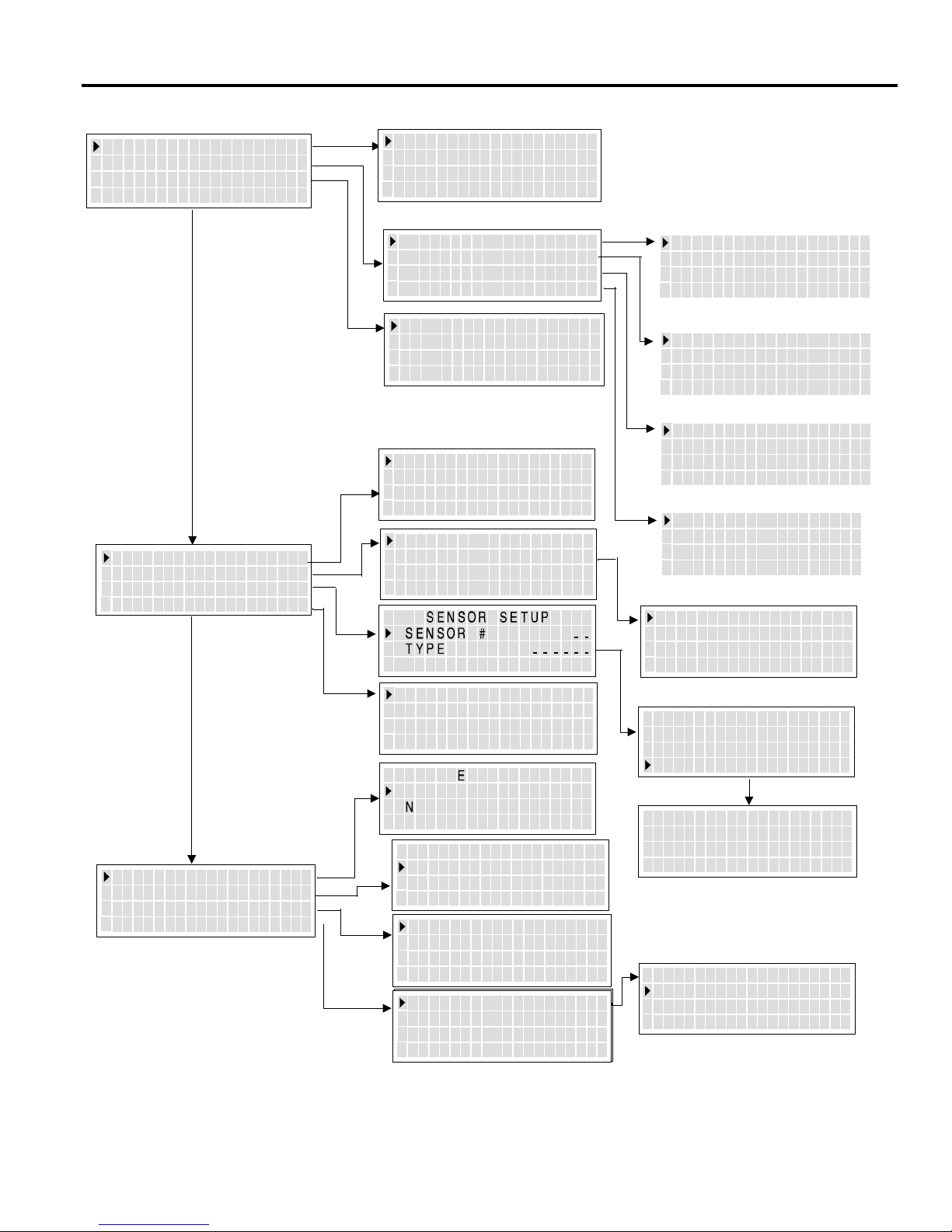
OPERATION HeatNet Control REV 1.38-1
Smith Series Advanced Menu Tree Version 1.38
DISTRIBUTED
CTRL
MODULAR BOILER SET
ADAPTIVE MOD
FIRING
FIRING MODE
BASE LOADING
SENSORS
4-20mA INPUT
MODE
CONTROL
H- NET
MASTER
H-NET ADDRESS
H- NET
YES
255
MODBUS ADDRESS
ADD BOILER
DELAY
DELAYSHED BOILER
MODULATE
MAXMOD
DELAY TIME
-
LAST
FIRE
MOD MODE: ADAPTIVE
DROP DOWN: ON PILOT
DELAY RELEASE :
MODE
MIN RUNTIME:
MIN OFFTIME
PREDICT START:
BASE LOAD BOILERS: 0
START > MOD
STOP FIRST
DELAY TIME
BRA
CAL I
TE? NO
TRUE
10 HRs
YES
10mins
0m
95
1
ADD DELAY TIME
4 MINUTES
0 SECONDS
SHED DELAY TIME
0s
2 MINUTES
0 SECONDS
MODULATE DELAY TIME
0 MINUTES
10 SECONDS
STOP MOD MAX
% 70
START PRIORITY 1
SET: FIRST
STOP PRIORITY 1
SET: LAST
PASSWORD
COMMUNICATIONS
DEFAULTSLOAD
SYSTEM
4mA SETPOINT
20mA SETPOINT
BOILER START
68°F
200°F
4.11mA
PRIORITY NORMAL
CLG
N
H
O
D
EW
COMMUN I CAT I ONS
BAUD 19200
DATA FORMAT 8E1
SETPOINT TIMER ON
:
-
:
P SSW R
- - - -
-
- - -
FACT ORY
OADA
- --
CAL?
RESET?
BOILER TYPE
CONFIGURE INTERLKS
LOAD F I RMWARE
LOAD F I RMWARE
OPTION: NO OPTION
OPTION: NO OPTION
APPL I CAT I ON HEAT
BOILER TYPE
NO
NOFACTORY
PLACE A
1K OR
CHANNEL
ON
TRIM OHMS
TRIM
FIRING PRIORITY : 2
BTU IN 2000,000
CONDENSING YES
OIL DIRECT FIRE NO
PRECI
1OK RES
VALUE
=
#
___
SET!
SI ON
I STOR
__
Page 69
Page 70

WORKSHEET HeatNet Control REV 1.38-1
2 3 4
° ° °
Worksheet
SETUP MENU
BOILERS
# of BOILERS
LEAD STAGE
HEAT BAND °
SETPOINTS
LOCAL SETPOINT °
OPERATE LIMIT °
OP LIM BAND °
SETPOINT SOURCE
OUTDOOR AIR RESET °
OA RESET
WARM WEATHER SD
WWS SETPOINT °
SET OA SETPOINTS
WATER TEMP °
@
HIGH OA TEMP °
WATER TEMP °
@
LOW OA TEMP °
PUMP OPTIONS
SYSTEM PUMP
POST PURGE TIME
ALWAYS ENABLED
SUMMER PUMP JOG
LOCAL PUMP
DELTA TEMP ENAB
DELTA TEMP °
POST PRGE TIME s
ALWAYS ENABLED
PUMP/VALVE OPTION
REMAINS ON:
LOCAL PUMP VFD
FLOW PROVE
NIGHT SETBACK
SETBACK ENTRY 1
ENTRY IS
SETBACK °
SETBACK TIME
START DAY
TIME
END DAY
TIME
OPTIONS
TEMP SCALE °
KEY CLICK
SKIP PASSWORD
BRIGHTNESS %
LOG/ RUNTIME
RUN HOURS
DATA LOG ENTRY
SIZE
BOILER CYCLES
AUX FUNCTIONS
COMBUST AIR DAMPER
Page 70
Page 71

WORKSHEET HeatNet Control REV 1.38-1
TYPE:
IN USE?
INPUT:
PROOF TIME
ALARM SILENCE SWITCH
IN USE
INPUT:
FAILSAFE MODES
H-NET COMM LOST
LOW TEMP:
TEMP <
HEAT EXCHANGER
EXCHGR DELTA T 40F
LIM-> HALF RATE
DHW SETPOINT
DHW DIFF
USE SENSOR?
DHW PRIORITY?
POST PURGE
DHW MASTER?
SYSTEM CLOCK
Page 71
Page 72

WORKSHEET HeatNet Control REV 1.38-1
ADVANCED SETUP
DISTRIBUTED CTRL
CONTROL
H-Net MASTER
H-NET ADDRESS
MODBUS ADDRESS
MODULAR BOILER SET
ADD BOILER DELAY
SHED BOILER DELAY
MODULATE DELAY TIME
MOD MAX – LAST FIRE
ADAPTIVE MOD
MOD MODE:
DROP DOWN
DELAY RELEASE
FIRING MODE
MODE
MIXED
START PRIORITY 1
SET:
STOP PRIORITY 1
SET:
MIN RUNTIME
MIN OFF TIME
PREDICT START
BASE LOADING
BASE LOAD BOILERS:
START > MOD
STOP
DELAY TIME
SENSORS
SENSOR #
TYPE
4-20mA INPUT
4mA SETPOINT
20mA SETPOINT
BOILER START
PRIORITY
PASSWORD
COMMUNICATIONS
BAUD
DATA FORMAT
SETPOINT TIMER
SYSTEM
BOILER TYPE
LOAD FIRMWARE
OPTION:
OUTDSIDE SUPPLY R E T U R N H E A D E R DHW 6 7 8
Version:
%
CALIBRATION SETTINGS
MIN VFD
IGN VFD
MAX VFD
Page 72
Page 73

TEMPERATURE REFERENCE HeatNet Control REV 1.38-1
Thermistor Resistance/Temperature Table
Temp °C Temp °F
-40 -40 336,450 60 140 2,488
-35 -31 242,660 65 149 2,083
-30 -22 176,960 70 158 1,752
-25 -13 130,410 75 167 1,479
-20 -4 97,072 80 176 1,255
-15 5 72,951 85 185 1,070
-10 14 55,326 90 194 915.4
-5 23 43,326 95 203 786.6
0 32 32,650 100 212 678.6
5 41 25,391 105 221 587.6
10 50 19,899 110 230 510.6
15 59 15,711 115 239 445.2
20 68 12,492 120 248 389.6
Resistance
Temp °C Temp °F
Resistance
25 77 10,000 125 257 341.9
30 86 8,057 130 266 301.0
35 95 6,531 135 275 265.8
40 104 5,326 140 284 235.4
45 113 4,368 145 293 209.0
50 122 3,602 150 302 186.1
55 131 2,986
Page 73
Page 74

TEMPERATURE REFERENCE HeatNet Control REV 1.38-1
RTD Stack Sensor Resistance/Temperature Table
Temp °C Temp °F Resistance Temp °C Temp °F Resistance Temp °C Temp °F Resistance
0 32 1,000 182 360 1,693 366 690 2,352
4 40 1,017 188 370 1,714 371 700 2,371
10 50 1,039 193 380 1,734 377 710 2,390
16 60 1,061 199 390 1,754 382 720 2,409
21 70 1,082 204 400 1,775 388 730 2,429
27 80 1,104 210 410 1,795 393 740 2,448
32 90 1,125 216 420 1,816 399 750 2,467
38 100 1,147 221 430 1,836 404 760 2,486
43 110 1,168 227 440 1,856 410 770 2,505
49 120 1,190 232 450 1,876 416 780 2,524
54 130 1,211 238 460 1,897 421 790 2,543
60 140 1,232 243 470 1,917 427 800 2,562
66 150 1,254 249 480 1,937 432 810 2,581
71 160 1,275 254 490 1,957 438 820 2,600
77 170 1,296 260 500 1,977 443 830 2,619
82 180 1,317 266 510 1,997 449 840 2,638
88 190 1,339 271 520 2,017 454 850 2,657
93 200 1,360 277 530 2,037 460 860 2,676
99 210 1,381 282 540 2,057 466 870 2,694
104 220 1,402 288 550 2,077 471 880 2,713
110 230 1,423 293 560 2,097 477 890 2,732
116 240 1,444 299 570 2,117 482 900 2,750
121 250 1,465 304 580 2,136 488 910 2,769
127 260 1,486 310 590 2,156 493 920 2,788
132 270 1,507 316 600 2,176 499 930 2,806
138 280 1,528 321 610 2,195 504 940 2,825
143 290 1,548 327 620 2,215 510 950 2,843
149 300 1,569 332 630 2,235 516 960 2,861
154 310 1,590 338 640 2,254 521 970 2,880
160 320 1,611 343 650 2,274 527 980 2,898
166 330 1,631 349 660 2,293 532 990 2,917
171 340 1,652 354 670 2,313 538 1,000 2,935
177 350 1,672 360 680 2,332
Page 74
Page 75
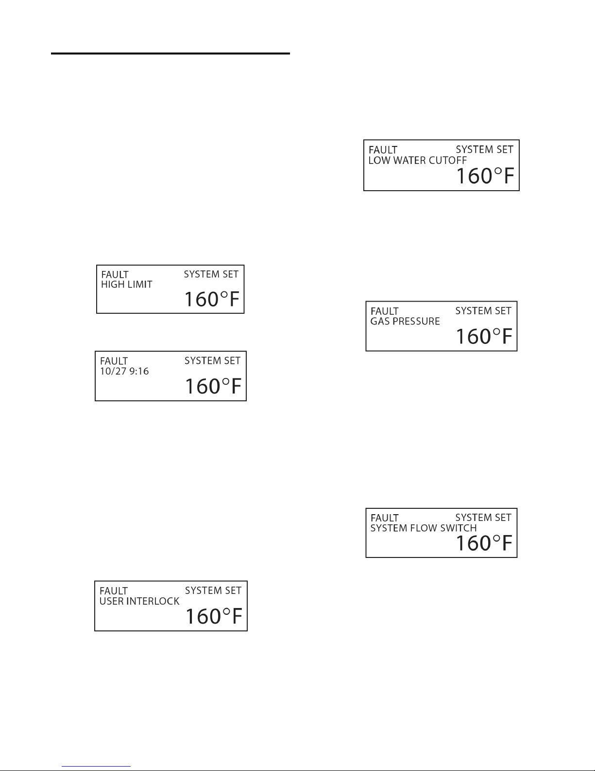
APPENDIX A HeatNet Control REV 1.38-1
*Status Screen Fault Display
There are numerous interlock switches and software limits
that are detected. Each of these, when tripped will produce a
display message, an audible beeping, and an alarm relay
closure. The fault is displayed first, then after a second, the
time the fault occurred is displayed. This cycle will keep
occurring until the fault is cleared.
These faults and interlocks are:
HIGH LIMIT:
When the high limit aquastat trips the following message is
displayed:
LOW WATER CUTOFF:
If there is a low water condition reported by the low water
cutoff switch this fault is displayed. Check that there is
water flow and water in the boiler. There is a reset switch
located on the LWCO box. The interlock connection is
located on J5B, LWCO.
GAS PRESSURE:
The gas pressure switches (high pressure and low pressure)
are connected in series, so if either trip, a fault will be
reported here. A reset switch is located on the gas pressure
switches. The interlock is located on J15B, GAS PR.
The high limit interlock breaks power to the ignition control
(shutting it off) and effectively removes any chance of the
gas valve receiving power. The HeatNet series control will
remain powered to display the fault, latch the alarm
relay/audible beeper, and to access the log. The interlock is
located on J5, HIGH LIMIT. Ensure power is present on the
input to the High Limit Control.
SPARE 4:
This is a reserved interlock input that is user defined. The
interlock is located on J5B, SPARE 4.
SYSTEM WATER FLOW:
Once the HeatNet series boiler receives a call for heat, it
closes the system circulator pump relay. It then waits 10
seconds or more (adjustable) to prove flow. If there is no
flow, the flow switch alarm will be set. Every 10 seconds
the circulator pump relay will cycle ON for 10 seconds and
then OFF for 10 seconds to try and establish flow. The
interlock connection is located on J5B, SYSTEM WTR
FLOW.
Page 75
Page 76
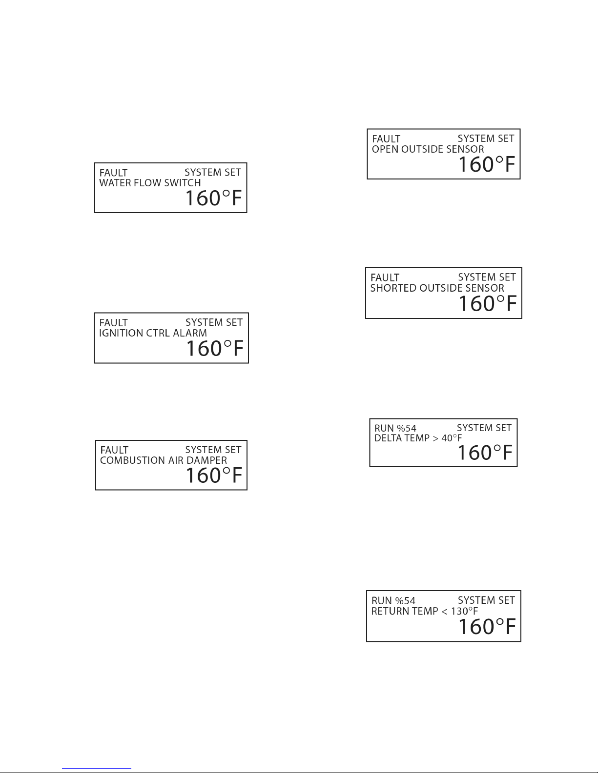
APPENDIX A HeatNet Control REV 1.38-1
WTR FLW LOCAL:
Once the HeatNet series boiler receives a call for heat, it
closes the LOCAL PUMP/VALVE relay. It then waits 10
seconds or more (adjustable) to prove flow. If there is no
flow, the flow switch alarm will be set. Every 10 seconds
the circulator pump relay will cycle ON for 10 seconds and
then OFF for 10 seconds to try and establish flow. The
interlock connection is located on J5B, WTR FLW.
IGNITION CTRL ALARM:
The ignition control alarm is displayed if the ignition
control detects a fault. This could be a flame failure, air
proving switch, or other fault associated with the ignition
control. When this fault occurs, you will need to refer to the
ignition control for the reason.
OPEN ******* SENSOR :
If the open sensor fault is displayed, the sensor in the
position reported was originally detected, but has since
opened. The boiler will shut down on any OPEN sensor
except the OUSTSIDE AIR sensor.
SHORTED ******* SENSOR:
If the shorted sensor fault is displayed, the sensor in the
position reported was originally detected, but has since
shorted. The boiler will shut down on any SHORTED
sensor except the OUSTSIDE AIR sensor.
DELTA TEMPERATURE WARNING:
COMBUST AIR DAMPER:
If the combustion air damper has been selected for use
(AUX FUNCTIONS), and the proof switch does not make,
this fault will be displayed.
When the master boiler receives a call for heat and needs to
start a boiler, the DAMPER relay closes on J13. If the
combustion air damper does not prove within the proof time
specified in the combustion air damper menu, the boiler will
not start and then display the fault. A combustion damper
fault on a boiler can only be cleared by power cycling.
If the temperature difference across the boiler measured
from RETURN water to SUPPLY water exceeds 40F this
message will be displayed. This can be set to an alarm
condition in the AUX FUNCTIONS menu. High delta
temperatures can result in damage to the boiler.
RETURN TEMPERATURE WARNING:
If the RETURN water temperature is less than 130F
(condensing) this message will be displayed. Return
temperatures less than 130F with the boiler running can
cause condensation of the flue gases. Condensation of flue
gases will damage the heat exchanger. Low return
temperatures for an extended period of time can result in
damage to the boiler.
Page 76
Page 77
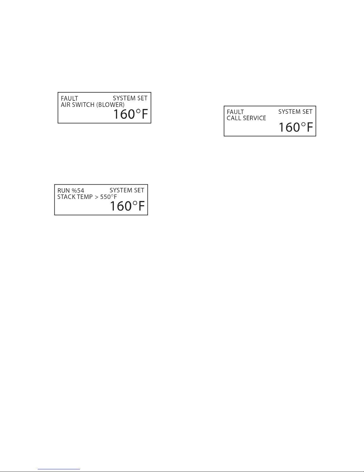
APPENDIX A HeatNet Control REV 1.38-1
AIR SWITCH:
If the IGNITION control closes its blower relay, the control
does not see the PILOT relay close within (2) minutes, and
the AIR PRESSURE switch is made, this message will be
displayed. This alarm protects the boiler from freeze ups
being caused by a blower bringing in cold outside air with
no fire.
STACK TEMPERATURE:
If the boiler’s stack temperature exceeds 550°F this message
will be displayed. If the stack temperature continues to rise
above 700 °F the boiler will be held in low fire.
CALL SERVICE:
If the H-Net control closes the last interlock string entering
the ignition control and the ignition control never closes its
Blower Relay, the H-Net control will wait 2 minutes. The
H-Net control will then retry for the duration of the local
pump post purge time and then retry the ignition sequence.
During this time “retry strt” will be displayed in the status
screen. After (5) attempts the H-Net control will lock out
and display call service.
Page 77
Page 78
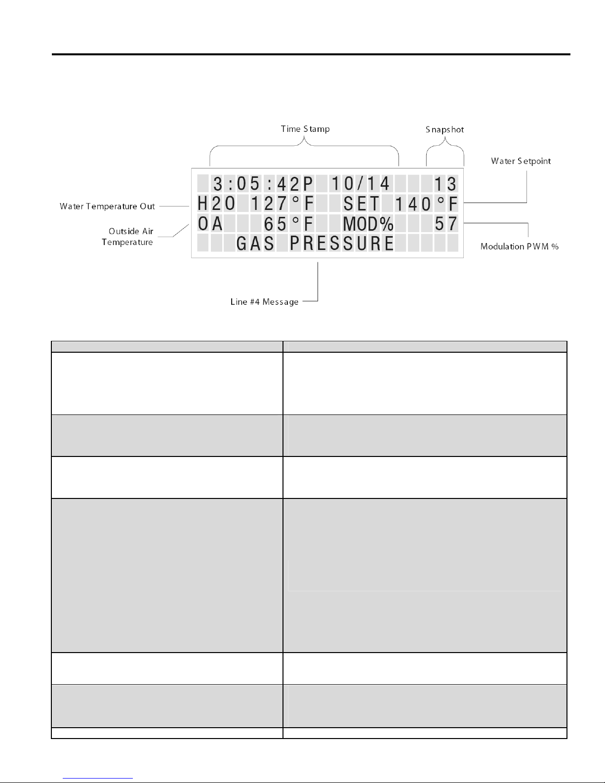
APPENDIX B HeatNet Control REV 1.38-1
Line # 4 Message
Description
Line 4 Log Entries:
The following table lists the messages on line # 4 of the log’s display.
SETBACK IS ACTIVE
SETBACK EXPIRED
NO LOCAL FLOW
NO SYSTEM FLOW
COMBUSTION AIR FAIL
SYSTEM RESET -- ----
O: stack overflow,
U: Stack Underflow ( both are software faults)
R: Reset Instruction ( Firmware or Default load),
W: Watchdog ( Firmware code ran erroneous code and
rebooted),
P: Power-ON (Power switch toggled),
B: Brown-out ( Microcontroller saw a voltage less than
4.5 VDC)
OUTDOOR RESET
HIGH DELTA TEMP
If any of the (4) temperature setbacks are active these log entries will
be displayed in the log.
If the test for flow fails these log entries will be displayed. The flow
proving switches are wired to J11A and J11B.
If the combustion air damper is used and does not prove across
J12B DAMPER, this message is displayed.
When the control is reset, this log entry captures the reason the reset
occurred.
This log entry indicates that Warm Weather Shutdown is in effect.
This log entry occurs when the temperature across the heat
exchanger has been greater than 40 degrees °F.
Page 78
Page 79

APPENDIX B HeatNet Control REV 1.38-1
Line # 4 Message
Description
LOW RETURN TEMP
SHUTDOWN UV TEST
STACK HIGH TEMP
HIGH LIMIT EXCEEDED
IGNITION CTRL ALARM
IRI Alarm
DOMESTIC HOT WATER
LOW WATER CUTOFF
VAR FREQ DRIVE
GAS PRESSURE
SPARE 4
OP LIMIT MECH
START FAILED, RETRY
OP LIMIT REMOTE
OPEN OUTSIDE SENSOR,
SUPPLY SENSOR,
RETURN SENSOR,
HEADER SENSOR,
DHW SENSOR
SHORTED OUTSIDE SENSOR,
SUPPLY SENSOR,
RETURN SENSOR,
HEADER SENSOR,
DHW SENSOR
If the return temperature is less than 130 degrees °F condensing
may be occurring.
After 24 hours of continuous runtime the ignition control module
needs to check it’s UV detection circuit. An orderly shutdown and
then a restart will occur. This log entry indicates that this has taken
place. This is not a fault.
This log entry occurs when the boiler’s stack temperature is greater
than 550 °degrees °F.
If the mechanical aguastat trips due to it’s high temperature setting
having been exceeded, this log entry will occur.
The ignition control module has faulted while performing an ignition
sequence, or while monitoring flame during normal operation.
If the gas valve proving circuit ( if equipped) detects a gas pressure
problem.
Indicates a call for DHW heating by either the DHW sensor or an
external thermostat.
These log entry faults are result of the interlocks connected to the
24VAC interlock inputs: J11A and J11B.
Low Water Cutoff = Low water condition in boiler
Var Freq Drive = The Variable Frequency Drive Interlock has tripped
Spare 4 = User installed interlock,
Op Lim Mech = An external operator (aquastat).
If the H-Net control closes the last interlock string entering the ignition
control and the ignition control never closes its Blower Relay, the HNet control will wait 2 minutes. The H-Net control will then retry for
the duration of the local pump post purge time and then retry the
ignition sequence. During this time “retry strt” will be displayed in the
status screen. After (5) attempts the H-Net control will lock out and
display call service. The Log will report the retries.
The is the firmware Operating Limit as defined in
SETUP:SETPOINTS:OPERATE LIM. When the Supply temperature
exceeds this value, this event is logged.
If one of the 10k thermistor sensors was detected to be open or not
connected, this fault will be logged.
If one of the 10k thermistor sensors was detected to be shorted this
fault will be logged.
Page 79
Page 80

APPENDIX B HeatNet Control REV 1.38-1
Line # 4 Message
Description
AIR SWITCH(BLOWER)
LOST BOILER #
FOUND BOILER #
FAIL SAFE H-NET LOST
FAIL SAFE LOW TEMP
BASE LOAD BOILER
CALL SERVICE
If a call is made to the ignition control to start and the HeatNet control
detects a blower start, but no Pilot within two minutes, the boiler locks
out. This log entry indicates that the blower was ON with no flame in
the boiler. Freeze up protection.
These log entries indicate that HeatNet has either discovered a boiler
or lost a boiler using it’s auto detection algorithm.
If the Fail Safe modes are active, these log entries indicate that they
became active for some reason and the boiler had entered Fail Safe
mode.
The Base load Boiler Relay K8 is Active if ON
Inactive if OFF
If the H-Net control closes the last interlock string connected to the
ignition control and the ignition control never closes its Blower Relay,
the H-Net control will wait 2 minutes. The H-Net control will then retry
for the duration of the local pump post purge time and then retry the
ignition sequence. During this time “retry strt” will be displayed in the
status screen. After (5) attempts the H-Net control will lock out and
display call service.
Page 80
Page 81

Page 82

Smith
260 North Elm Street
Westfield MA 01085
 Loading...