

Page 1

TABLE OF CONTENTS Page No.
Specifications 3
Bladder 5
Fire Door 6
Air Supply 8
Anti-Rollout Device and Ash Auger Tube 10
Supply Line and Return Line Threaded Connectors 11
Low Water Cutoff 11
Outer Door 11
Site Preparation Specifications 12
Pad Specifications 13
Wiring Diagram 14
Updated: 07/10/12
1
Page 2
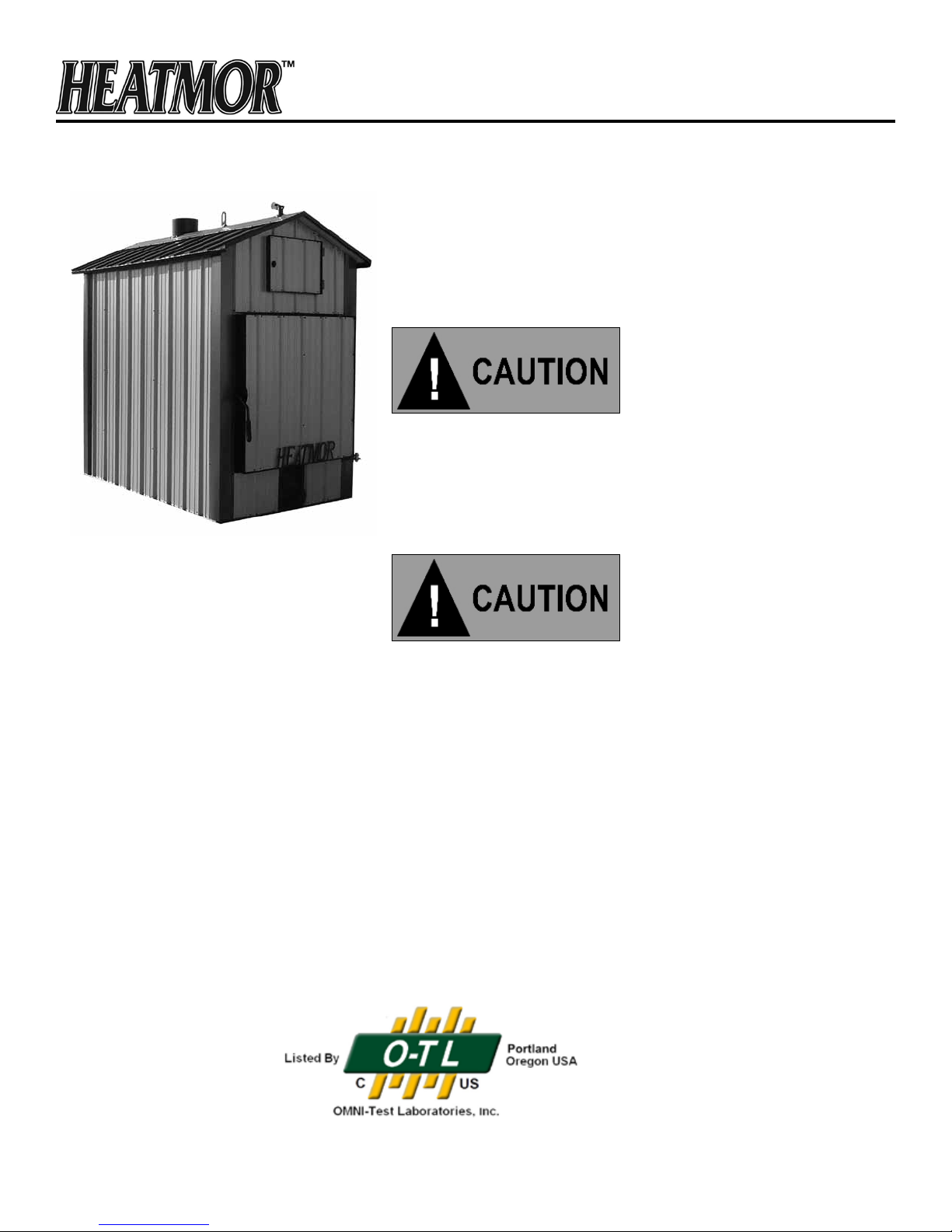
MODEL 600 CSS STAINLESS STEEL OUTDOOR FURNACE
INSTALLATION SHOULD BE PERFORMED BY A
QUALIFIED INSTALLER AND WILL COMPLY WITH ALL THE
REQUIREMENTS OF THE AUTHORITY HAVING JURISDICTION
OVER THE INSTALLATION.
READ THROUGH THE ENTIRE OPERATORS AND
MAINTENANCE MANUAL AND THIS SUPPLEMENT BEFORE
OPERATING YOUR HEATMOR STAINLESS STEEL OUTDOOR
FURNACE MODEL 600 CSS.
NOTE: NEVER START A FIRE INSIDE THE FIREBOX UNTIL THE
WATER JACKET IS FULL OF WATER AND SAND HAS BEEN
ADDED TO THE BASE TO THE CORRECT LEVEL.
Units are Safety Listed by Omni Test Laboratories
Report # 275-O-12-4
Listed to UL2523-2009 and CSA B366.1-11
2
Updated: 07/10/12
Page 3
MODEL 600 CSS FURNACE SPECIFICATIONS
Specications Model 600 CSS
Overall Width (Inches)
Base Width (Inches) (Footprint)
Overall Height (Inches)
(With chimney)
Overall Length (Inches)
Base Length (Inches)(Footprint)
Total weight (lbs.)
(Without Water)
68
61
106
102
92
2800
Water Capacity (US. Gal.) 285
Forced Draft (C.F.M.)
150 secondary
150 primary
Chimney Size (Inches) 10
Wood Length (Inches) 60
Insulated Heating Area (Sq. Ft.)*
1 Loading per day
2 Loading per day
Approx. 9000
Approx. 18000
Firebox Width (Inches) 38
Firebox length (Inches) 60
Firebox height (Inches) 48
Volume of rebox (Cu. Ft.) 63
Firebox Door Size (Inches) 30 x 36
Flue transfer area (Sq. Ft.) 25
BTU’S (maximum)** 600,000
Water Jacket Steel
Gauge
Firebox Steel
Gauge
Base Steel
Gauge
Stainless
7
Stainless
7
Stainless
7
Base of Unit to Bottom of Loading Door (inches) 18
Sand required during initial setup. 1/2 yd.
Warranty – Workmanship
(Includes total unit)
Limited LIFETIME Warranty
*This is an estimate only. Actual loadings per day may vary depending on structures heated and type of wood used.
**This value should only be used as an indication of the furnace’s heat recovery ability. Sustained outputs at this rate will increase the loadings per day.
Some types of wood may prevent the furnace from reaching this maximum output.
Updated: 07/10/12
3
Page 4
MODEL 600 CSS FURNACE SPECIFICATIONS (CONTINUED)
Warranty –Corrosion
(Includes total unit)
Approvals Test Standards
Limited LIFETIME Warranty
UL 2523 - 2009
CSA-B366.1-11
Hookup Location Back
Total Heat Extraction area sq.ft 109
Type of Fuel WOOD ONLY
Electrical Supply
1 Phase
115 Volts, 60HZ
Updated: 07/10/12
4
Page 5
Bladder
Principle of the Bladder
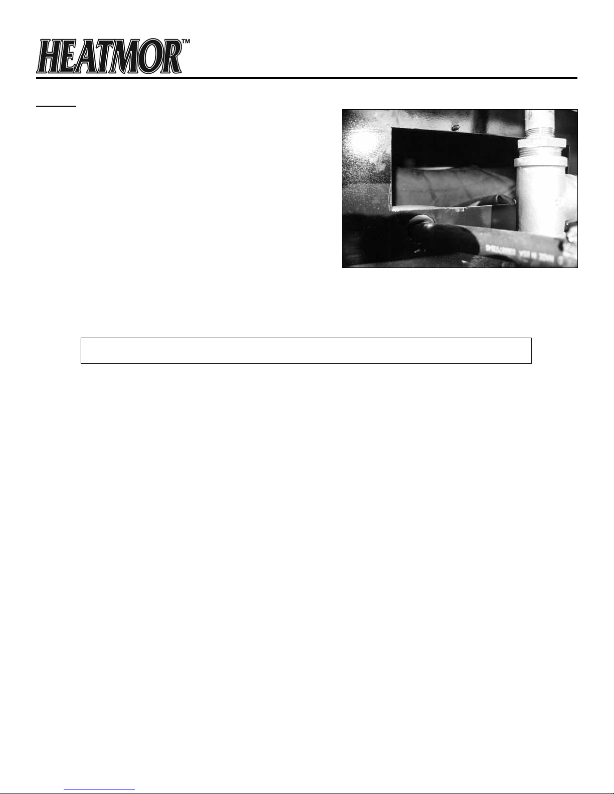
The Bladder of the Model 600 CSS operates on the same
principles outlined in the “Bladder Assembly” section of the
Operators and Maintenance Manual. It is located behind
the upper front access door. Remove the thumbnut and the
cover lifts out to reveal the bladder.
Refer to the “Bladder Assembly” section of the Operators
and Maintenance Manual for information on:
1) Operation of the bladder
2) Filling the bladder with water
3) Maintenance of the bladder
The Model 600 CSS bladder should be approximately ¾ full at normal operating temperatures.
Removal and Replacement of the Bladder
Do not attempt replacement unless furnace water temperature is less than 100°F (38°C)
1) Turn off the bladder gate valve located behind the top front access door.
2) Remove the bladder cover plate by loosening the thumbnut and pulling out the plate.
3) Loosen the hose clamp from the bladder gate valve.
4) Pull the bladder hose from the gate valve and allow the water from the bladder to drain. USE
CAUTION! THIS WATER CAN BE WARM.
5) Remove the old bladder and re-install the new bladder.
6) Push the new bladder hose onto the bladder gate valve and tighten the hose clamp.
7) Open the bladder gate valve and then refer to “Filling the Bladder with Water” from the Bladder
Assembly section of the Operators and Maintenance Manual to rell the bladder to the correct level.
Filling the HEATMOR™ Outdoor Furnace Model 600 CSS Initially with Water
See the “Filling the HEATMOR™ Furnace Initially with Water” section of the Operators and Maintenance
Manual.
Updated: 07/10/12
5
Page 6
Fire Door
Principles of the Fire Door
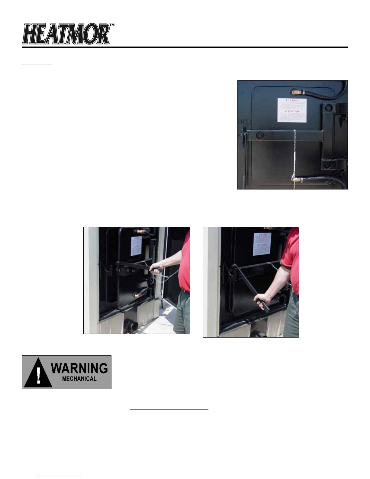
The Model 600 CSS re door is water cooled to prevent warping of the
door. It also absorbs heat from the re and transfers heat to the water,
adding a heat-exchanging surface. Because it is water cooled, the
outer surface will never be hotter than the water in the furnace.
Removal and Replacement
If your re door needs to be removed or replaced on your Model 600
CSS, please contact your local dealer for assistance.
Opening the Fire Door
It is important to always stand behind the re door when opening
it. Open the door just slightly to allow air to the rebox. This clears
the rebox of smoke that may be lingering in the rebox. Once the
smoke is evacuated from the rebox it is safe to open the door fully,
always standing behind the door for safety. Refer to the “Safe Furnace
Operation Guidelines” section of the Operators and Maintenance manual for further instruction on safe opening
of the re door.
Refer to Safe Operating Guidelines for further instructions on how to safely open and close the re
door or contact your local dealer. Ask for a demonstration.
Updated: 07/10/12
6
Page 7

Adjustment of the Model 600 CSS Fire Door
The re door hinges of the Model 600 CSS are stronger, more permanent, hinges than the residential models.
Unlike the residential models, the hinges are not utilized for adjustment.
There are two major parts that make up the re door of the Model 600 CSS, the door water jacket and the
door-mounting frame. The water jacket is mounted to the door frame with three one inch threaded studs and
held in place with two jamb nuts and two washers on each stud. When making adjustments, it is important
not to loosen more than two studs at a time. The holes in the doorframe are larger than the studs to allow
for movement required to align the door with the doorframe. Please follow the recommended instructions for
proper adjustment of the re door or contact your local dealer for further details.
If there is smoke leakage around the re door at any point, and the gasket has been found to not be the
problem, the door should be adjusted. Prolonged exposure to smoke and heat can cause permanent damage
to the re door gasket, magnify leakage problems, and create safety concerns. If the door seems to be aligned
properly with the re door frame, adjusting the re door towards the re door frame will likely solve the leakage
problem. Using a socket, loosen the outer and inner nuts located on the horizontal door support arm. This will
move the door towards the rebox creating a tighter seal between the door seal gasket and doorframe. Once
the door has been adjusted to the correct depth, the inner and outer nuts should, once again, be tightened
against each other to hold the door in that position.
Alignment of the Fire Door
1) The re door should be positioned over the re door frame so that there is an equal distance
between the re door and the re door frame on all four sides. Generally, this can be achieved by
returning the three adjustment studs to the center of their respective holes. The model
600 CSS re door is heavy; safe adjustment can be done with the assistance of a
hydraulic or manual jack and a small pry bar. Loosen the doorframe jamb nuts just enough to
allow the door to move. Center the door vertically in the frame. Move the door horizontally right
to left with the use of a small prybar between the door mounting frame and a jamb nut. When
the water jacket is centered on the doorframe, the jamb nuts should all be tightened.
2) The next procedure is to seat the door water jacket evenly around the re door frame. It is best to
start with the water jacket away from the re door frame approximately a 1/4”.
3) If the right side of the door is not seated against the re door, loosen the top right adjustment, rst
the outer jamb nut, then the inner jamb nut may be turned until the water jacket is seated about
1/8” into the silicone seal.
4) Follow the same procedure on the bottom adjustment until the right edge is seated evenly. Now
tighten the bottom adjustment.
5) To ensure the left side of the door is sealed, follow the same procedure as the right side with left side
adjustment only.
Updated: 07/10/12
7
Page 8
Remember: When adjusting the seating of the re door, loosen only one adjustment at a time.
After completion, make sure all jam nuts are tight.
Fire Door Chain
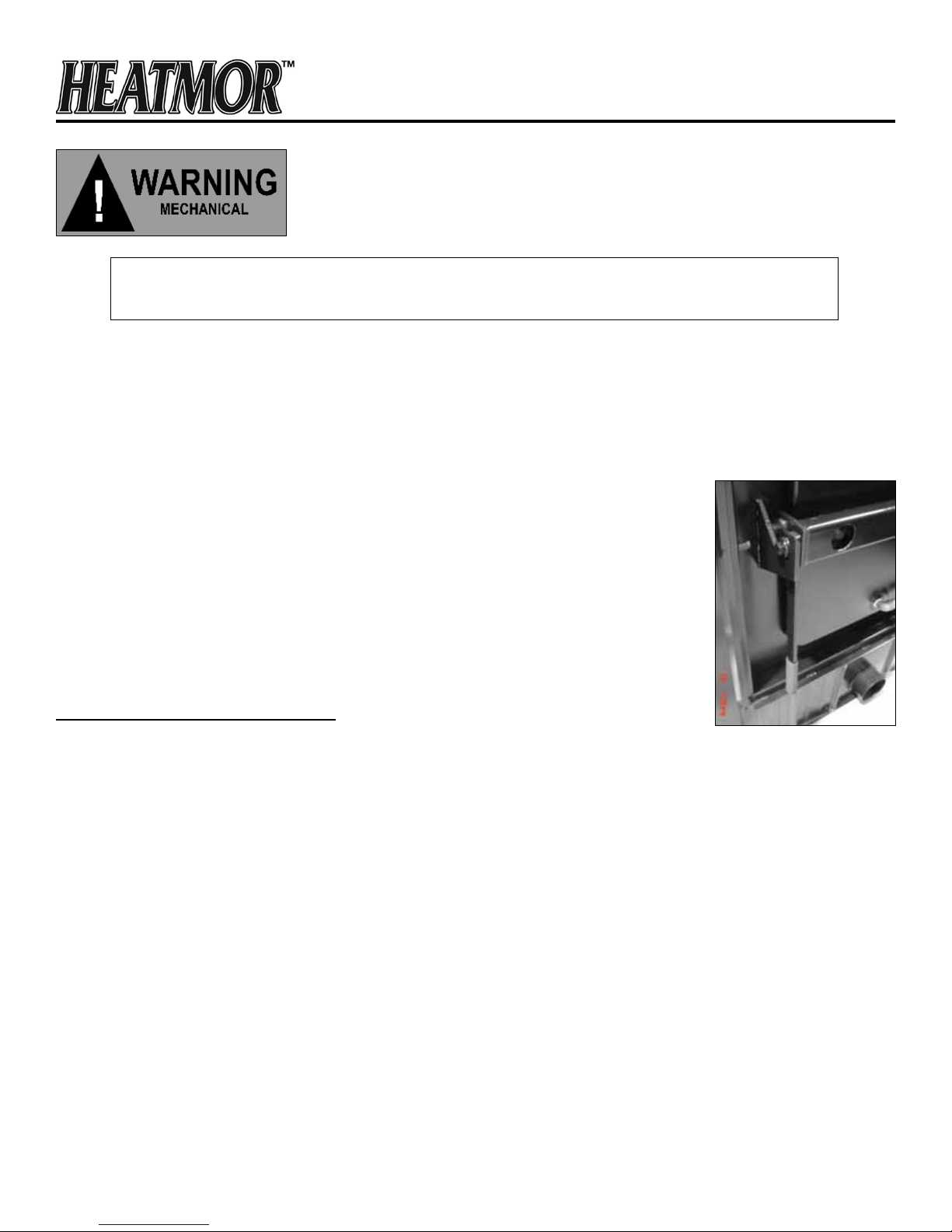
The re door chain prevents the outer door of the Model 600 CSS from swinging open uncontrollably. It is
recommended to install a post to the side of the furnace, to secure the outer door from opening or closing during
loading and maintenance procedures. See the “Site Preparation Specications” drawings further on in this
supplement.
Fire door Latch
Principles of the Fire Door Latch
The purpose of the re door latch is to secure the re door during operation. The re
door latch is not adjustable on the Model 600 CSS.
Fill Line
The purpose of the Fill Line is to avoid a situation where the furnace is overlled
with wood. An over lled furnace will smoke more than one that has been properly
lled with wood. A properly lled furnace will have less problems with debris in the
secondary airbox.
Combustion Blower Power Switch
Principle of the Combustion Blower Power Switch
The Combustion Blower Power Switch is located at the front of the unit, making it easy to switch the blowers
on or off during loading or maintenance.
Removal and Replacement
To remove the Combustion Blower Power Switch, use the following steps:
1) Turn off the main electrical power supply to the HEATMOR™.
2) Remove the switch cover plate.
3) Make a sketch of the location of the wires on the switch.
4) Remove the wires and replace the switch.
5) Replace the wires to the original locations.
6) Secure the cover plate.
7) Turn the main electrical power supply back on to the HEATMOR™.
Note: It is recommended to contact a licensed electrician to perform the above operation.
Updated: 07/10/12
8
Page 9
Combustion Air Blowers
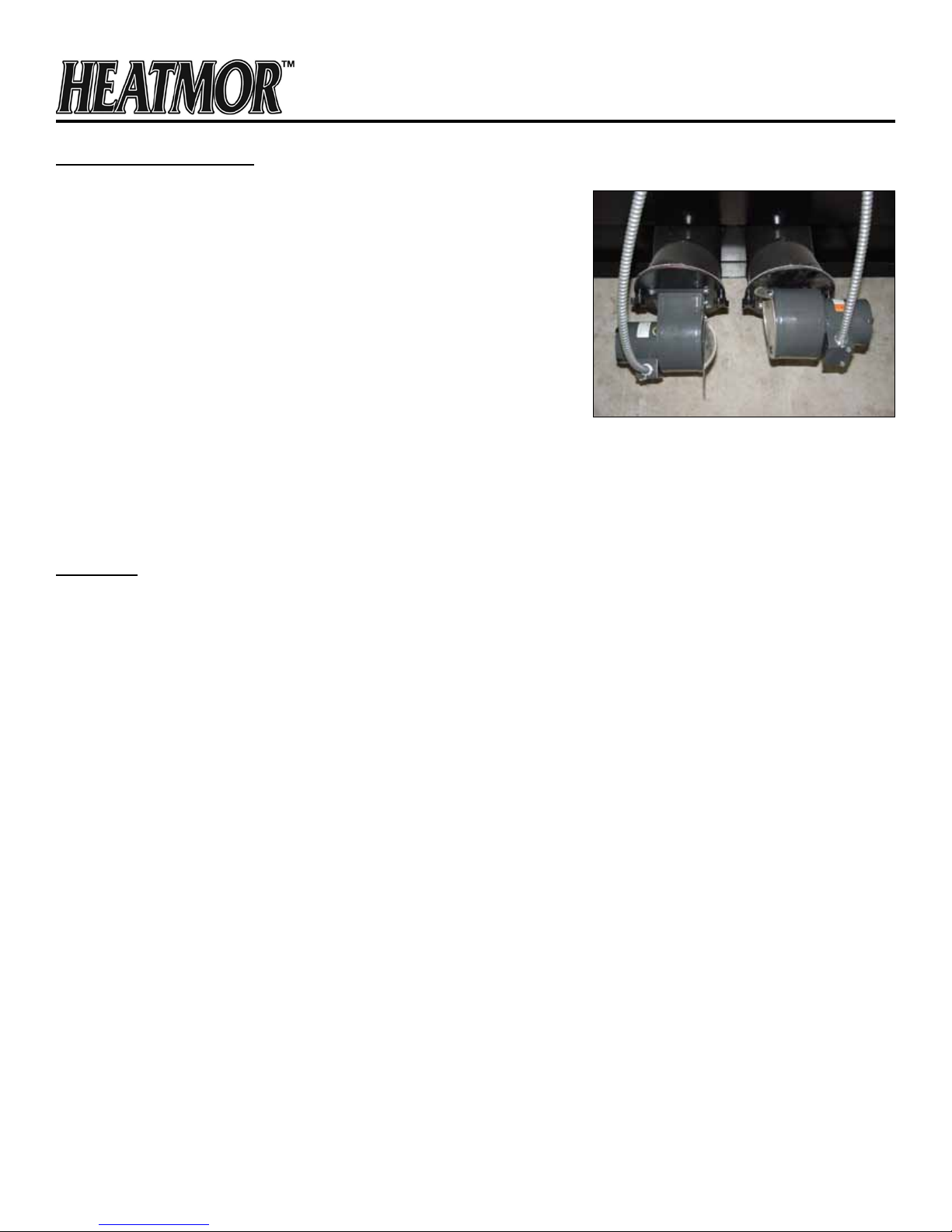
The model 600 CSS has two 150 CFM blowers. The blower on the left,
also called the primary air, delivers air to the re from below the grates.
The blower on the right, also known as the secondary air, delivers air
into the rebox by means of an airbox on the inside, rear, wall of the
rebox. The airow of each blower is adjustable by means of a damper
installed on each. This adjustable air ow is key to getting the most
efciency from your model 600 CSS Outdoor Furnace.
Principle
Refer to the “Wood” section of the Operators and Maintenance
Manual to gain a better understanding of how wood burns and the
stages of combustion.
The air delivery of the model 600 CSS is different than the residential models because it supplies air to two
areas of the re. The primary air is supplied under the re and is responsible for creating smoke and getting
the temperature above 500°F. The secondary air is introduced into this smoke above the wood stack allowing
the smoke to combust, creating higher re temperatures and less smoke.
Air Supply
Depending on the type of wood fuel used, different amounts of primary and secondary air are required for optimal
efciency. For example, small pieces of wood (high surface area) with low moisture content requires a small amount
of primary air and a large amount of secondary air. If the opposite is done, with this type of fuel, an over-fueling
situation will likely exist and the furnace will lose efciency and smoke more. Cordwood with high moisture (30 - 40
percent) will likely require a lot of primary air and medium to large amounts of secondary air. A properly red furnace
will operate at optimum efciency with the least amount of visible exhaust. Once the operator is familiar with their
type of fuel, they will not need to adjust the dampers on the fans.
Operation
The blowers are controlled by the “Water Temperature Range Control” aquastat. When the water temperature
reaches the low set point of the aquastat, the aquastat will supply power to the fans until the water temperature
reaches the high set point of the aquastat. When the high set point is reached, the aquastat terminates the
power supply to the fans. The dampers on the blowers give control over the airow while the aquastat is
supplying power to the blowers.
Maintenance
Refer to the “Air Supply” section of the Operators and Maintenance Manual fur further information on
maintaining the air combustion blowers.
Flipper Assemblies
See the “Air Supply” section of the Operators and Maintenance Manual.
Updated: 07/10/12
9
Page 10
Secondary Air Box
Operation
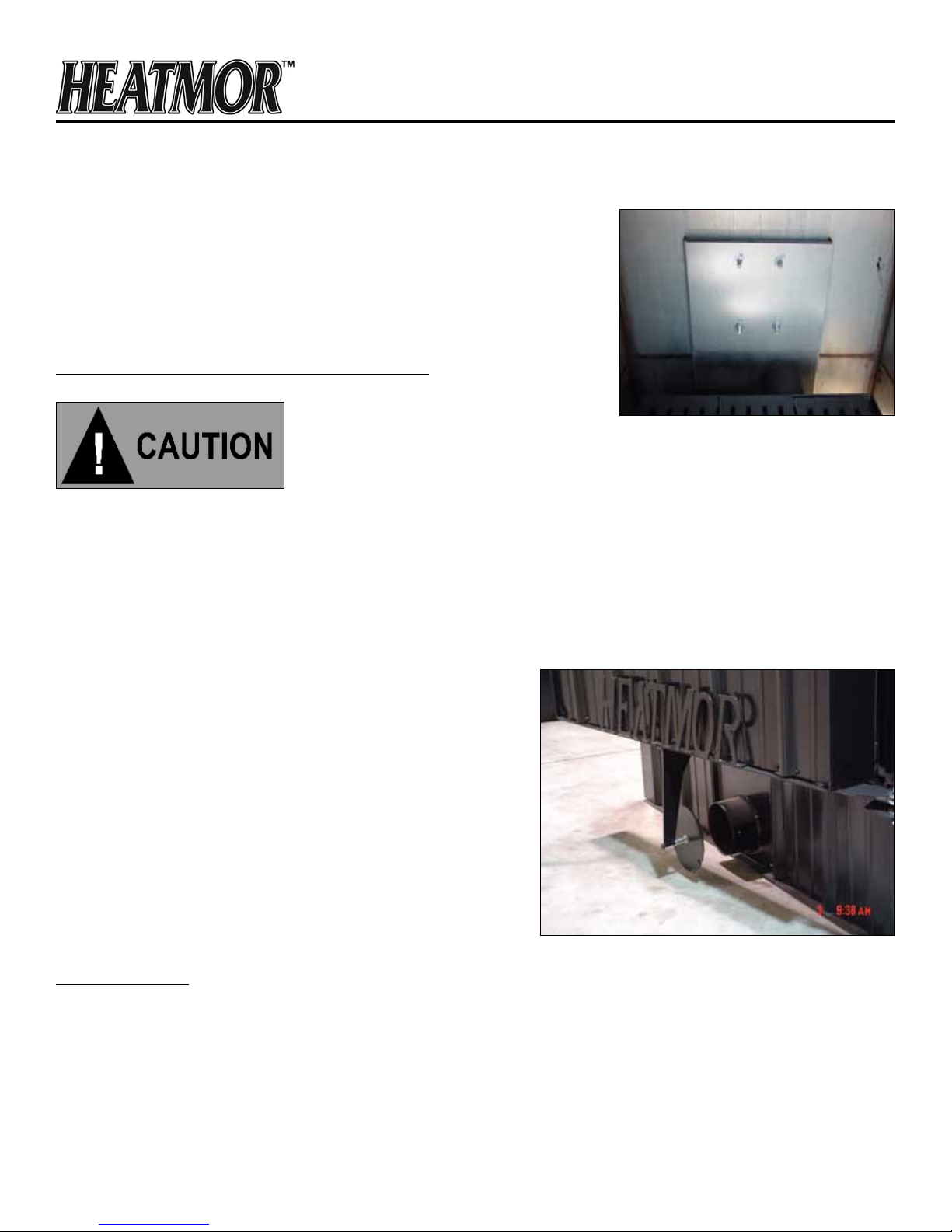
The Secondary Airbox is located along the rear, interior, rebox wall.
It is a means to direct air from the secondary combustion air blower to
the upper area of the rebox. This is how smoke from the re can be
ignited. Do not stack anything over the opening of the secondary airbox
as poor combustion could occur.
Anti-Rollout Device (A.R.D.) and Auger Tube
THE A.R.D. MUST OPERATE PERFECTLY OR PROBLEMS QUICKLY ARISE.
Anti-Rollout Device
Principle
The Anti-Rollout Device (A.R.D.) is a safety feature that allows air into the rebox before the main re door is
opened. Along with normal, recommended, safe re door opening practices, the risk of a ash back is greatly
reduced.
Operation
The A.R.D. opens and closes automatically with the operation of
the outer door.
Maintenance / Result
Ensure ash, shavings or small wood pieces do not become
lodged in the A.R.D. Make sure that the spring on the auger
tube cover is working properly. This ensures a compression t
of the cover to the auger tube. If the A.R.D. is not closing 100
percent, a constant air leak will allow air to continually fuel
the re. This will cause a smoldering re resulting in creosote,
boiling, and premature warping of the ashpan grates.
Ash Auger Tube
Principles
The Anti-Rollout Device also serves as the ash auger tube. Opening the outer door will expose the auger tube.
The auger tube cover is located under the front outer door of the furnace. The cover must have a good seal
against the auger tube.
Updated: 07/10/12
10
Page 11
Ash Removal
1) When removing ashes, always turn off the combustion air blowers.
2) Open the outer door, which releases the auger tube cover plate.
3) Insert the ash auger and remove the ashes.
Supply Line and Return Line Threaded Connectors
There are two 1.5” Supply line and two 1.5” Return line threaded connectors (female NPT) located at the back
of the Model 600 CSS. A brass nipple should be used to connect any ttings to the threaded spuds. Refer to
the “Supply Line and Return Line Threaded Connectors” section in the Operators and Maintenance Manual.
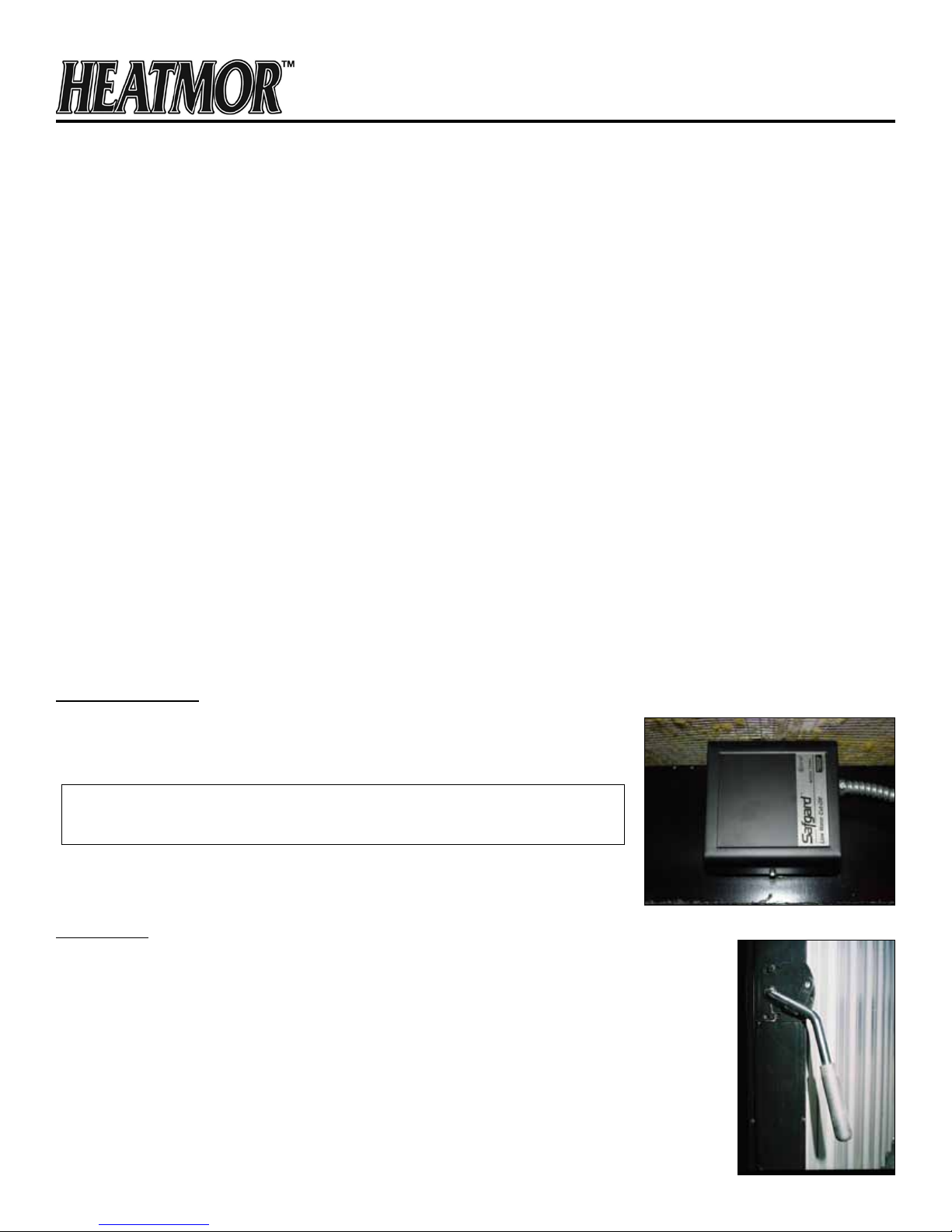
Low Water Cutoff
Principles
The low water Cutoff (located above the ue) shuts down power to the fans
when the water in the furnace is low.
The only way to restore power to the fans is to ll the furnace with water.
Do not ll a warm furnace with cold water.
Outer Door
Operation
The outer door on the rebox is hinged and latched separately from the internal re
door. The door is hinged and opens to the right of the furnace. As the door opens it
releases the A.R.D. auger tube cover plate, which allows air to enter the rebox before
the re door is opened, reducing the risk of a ashback. It is strongly recommended that
a post is installed to the outside corner of the opened door to fasten the back and front
external doors secure while in the open position. This reduces the risk of injury caused
by the sudden movement of either large door (see drawing supplied).
Updated: 07/10/12
11
Page 12
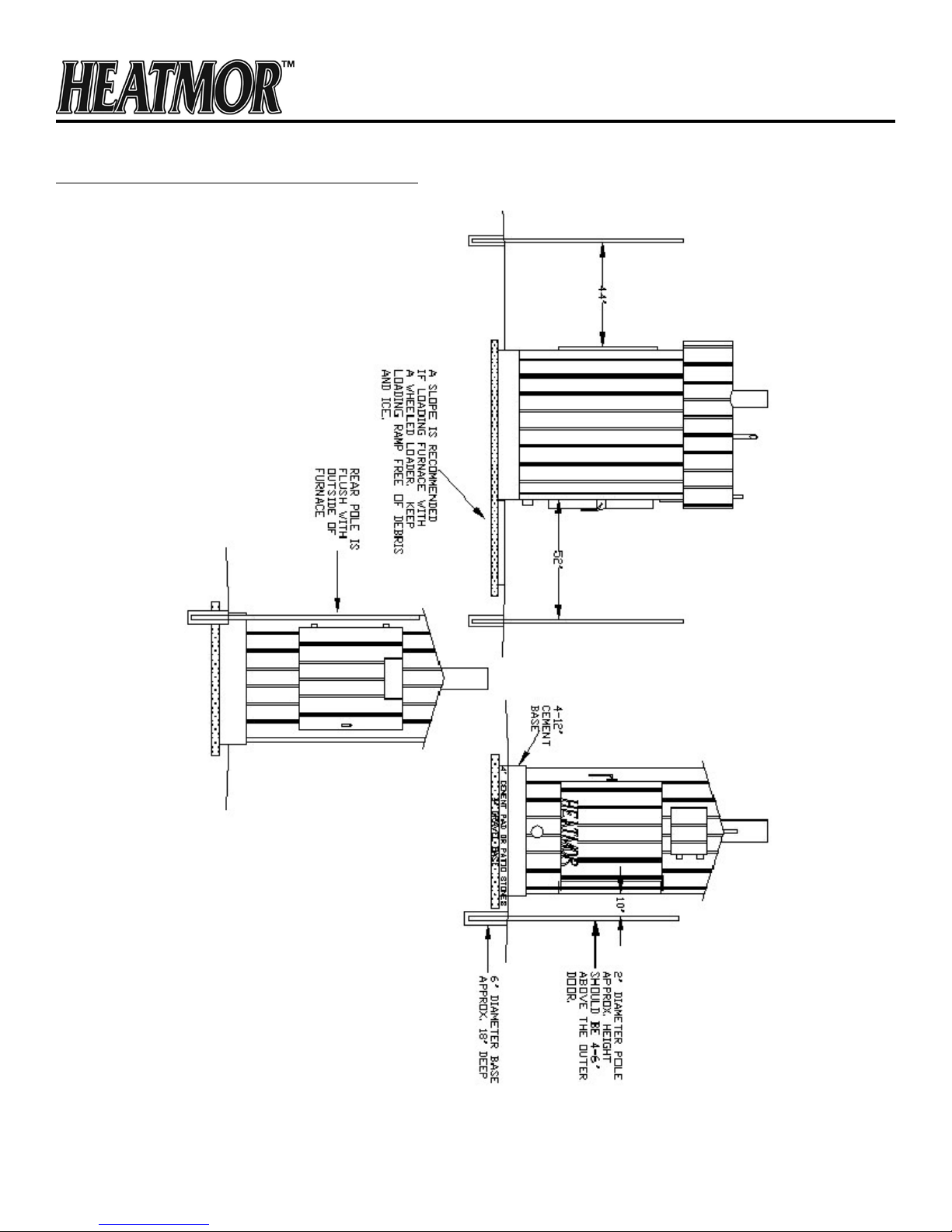
Site Preparation Specifications – Model 600
Updated: 07/10/12
12
Page 13
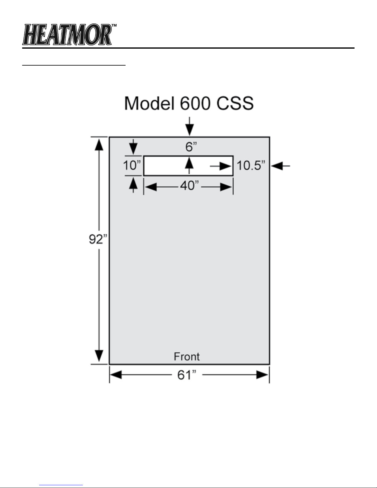
Pad Specifications – Model 600
Notes:
1. Pad sizes are shed base dimensions plus 3 inches in width and 2 inches in length.
2. Pad thickness must be at least 4 inches but not more than 12 inches.
3. All measurements are in inches.
Updated: 07/10/12
13
 Loading...