

Heatmor 200X, 350X, X Operation And Maintenance Manual


When these safety symbols appear on the following pages, they will alert
you to the possibility of serious injury if you do not comply with the corresponding instructions. The hazard may originate from something mechanical or electrical shock. Please read the instructions carefully.
When you see this safety symbol on the following pages, it will alert you
to the possibility of damage to your HEATMOR™ Stainless Steel Outdoor
Furnace if you do not comply with the corresponding instructions. Please
read the instructions carefully.
The HEATMOR™ Stainless Steel Outdoor Furnace is certied to offer safe
service provided it is installed, operated and maintained in accordance with
the instructions contained in this manual.
Proper personal protective equipment (PPE) MUST BE WORN AT ALL
TIMES when servicing and maintaining any of the HEATMOR™ Stainless
Steel Outdoor Furnace product line.
This manual describes the installation and operation of the HEATMOR™
200X and the HEATMOR™ 350X cataytic equipped wood heater. These
heaters meet the 2015 U.S. Environmental Protection Agency’s crib wood
emission limits for wood heaters sold after May 15, 2015. Under specic
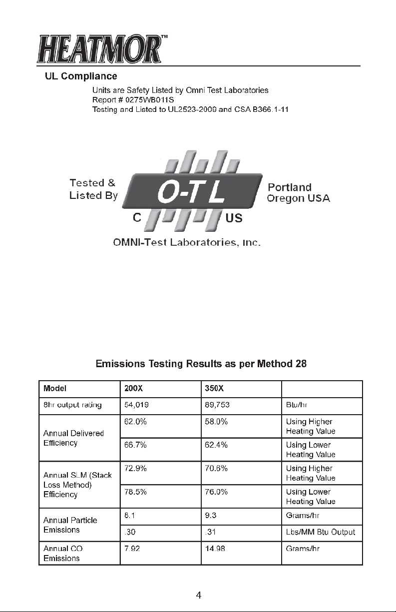
test conditions the 200X can output 54,019 Bru/hr. Under specic test con-
ditions the 350X catalytic equipped wood heater can output 89,753 Bru/hr.
This wood heater has a manufacturer-set burn rate that must not be altered.
It is against federal regulations to alter this setting or otherwise operate
this wood heater in a manner inconsistent with operating instructions in
this manual.
The 350X contains a catalytic combustor, which needs periodic inspection
and replacement for proper operation. It is against federal regulations to
operate this wood heater in a manner inconsistent with operating instructions in this manual, or if the catalytic element is deactivated or removed.
ii

TABLE OF CONTENTS Page #
I NOTICE TO THE READER 1
II EPA PHASE HANGTAG X-SERIES 2-3
III UL COMPLIANCE & EMISSIONS TESTING RESULTS 4
1 HEATMOR™ X-SERIES OUTDOOR FURNACE MODEL 5
FURNACE SPECIFICATIONS 6
2 FRONT CUT AWAY VIEW OF HEATMOR™ X-SERIES FURNACE 7
FURNACE PARTS LIST 8
3 REAR CUT AWAY VIEW OF HEATMOR™ X-SERIES FURNACE 9
FURNACE PARTS LIST 10
4 MINIMUM CLEARANCE SEPARATION SPECIFICATIONS 11
5 WARNINGS AND PRECAUTIONS 12
A Installation 12
B Electrical 13
C Other 13
6 CONCRETE PAD SPECIFICATIONS 14
7 INSTALLATION OF THE HEATMOR™ FURNACE 15
A Equipment Required 15
B Placing the HEATMOR™ on the Concrete Pad 15
C Caulking Around the Firebox Base 15
D Caulking Around the Outside Perimeter of HEATMOR™ 15
E Filling the HEATMOR™ Outdoor Furnace Initially with Water 16
F Maintaining Water in the Bladder and in the HEATMOR™ 17
G Initial Installation of Sand 18
i. Types of sand to use
ii. Installation 19
H HEATMOR™'s recommended Installation Instructions diagrams 19-21
8 SAFE OPERATING GUIDELINES 22
A Operation 22-23
B Lighting Your HEATMOR™ for the First Time 24
C Dew Point 25
D Loading Wood into the HEATMOR™ 26
E What should I burn? 27
F How does a fire burn out? 28
G Types of Wood 28
H Wood as a Fuel 28
I Stages of Combustion 29
J Efficiency Measurements 30
K Loading of the Furnace 30
L Handling and Storage of Wood 31
iii

9 WATER 32
A Qualities of Water to Use 32
B Water Level Maintenance 32
C Removal/Replacement of System Water 32
D Water Additives 33
E Water Treatment Additives and Safety Specifications 34
F Freeze Protection 35
G Adding Freeze Protection Products 36
10 BLADDER ASSEMBLY 37
A Bladder 37
B Removal and Replacement of the Bladder 38
C Bladder Gate Valve and Bladder Hose 38
D Water Level Switch 39
11 WATER JACKET 40
A Water Jacket 40
B Supply Line and Return Line Connectors 40
C Relief Vent Pipe and Pop-off Ball 40
12 FIREBOX AND OTHER COMPONENTS 41
A Firebox 41
B Firebox Door 42
C Firebox Door Hoses and Elbows 44
D Firebox Door Handle 45
E Firebox Door Hinge 45
F Firebox Door Latch 46
G Firebox Door Holder 46
H Firebox Door Gasket 46
I Firebox Door Frame 47
J Firebox / Base Connector Clamps 48
K Fire-brick 48
L Standard Grates 48
M Sand 49
i. Types of sand to use 49
ii. Installation 49
13 AIR SUPPLY 50
A Combustion Air Blower and Flipper Assembly 50
i. Operation of the Combustion Air Blower and Flipper Assembly 50
ii. Steps to Maintain your Blower / Flipper Assembly 51
B Air Box(s) 52
C Automatic Fan Switch (A.F.S.) 53
14 CHIMNEY AND TOP FLUE 54
A Chimney 54
B Chimney Extension(s) 54
iv

C Flue 55
D Flue Cover 55
E Flue Scraper 55
15 ASHES 56
A Ash Management and Ash Removal 56
B Ash Pan 57
C Ash Auger 57
D Ash Auger Tube 58
E Ash Auger Tube Cover Plate 58
F Creosote 58
16 ELECTRICAL 59
A Electrical Supply 59
B Electrical Supply Junction Box 59
C Double Electrical Outlets at rear 59
D Electronic Aquastat Controller 60
E Temperature Probe 61
F High Water Temperature Safety Shutoff Control 62
G Front Light and Fan Power Switch 63
17 EXTERIOR CLADDING AND INSULATION 64
A Outer Door of HEATMOR™ 64
B Roof of the HEATMOR™ 64
C Sides of the HEATMOR™ 65
D Insulation 65
18 AIR LEAKS 66
A Checking For Air Leaks 66
B Why do we not want any air leaks? 66
19 DOMESTIC COIL (OPTIONAL) 67
20 CATALYTIC CONVERTER (350X) 68
A Operation/Maintenance 68
B Removal 69
C Cleaning 70
21 SEASON START UP & MAINTENANCE 71
22 END OF SEASON & SHUT-DOWN MAINTENANCE 72
23 FREQUENTLY ASKED QUESTIONS 74
24 TROUBLESHOOTING AND SOLUTIONS 76-82
HEATMOR™ STAINLESS STEEL LIMITED WARRANTY 83
HEATMOR™ FOR LIFE 84
NOTES 86
v

Notice to the Reader
HEATMOR™ Inc. warrants and guarantees ALL HEATMOR™ Stainless Steel Outdoor
Furnace Models. HEATMOR™ Inc. does not warrant or guarantee any of the supporting
products described within this Operations and Maintenance Manual.
The contents, descriptions, directions, diagrams, and recommendations within this material
are for the sole purpose of suggested operation and maintenance methods.
Furthermore, HEATMOR™ Inc. shall not be liable for any special, consequential, or exemplary damages, resulting, in whole or part, from the readers’ neglectful use, based upon the
material within this Operations and Maintenance Manual. Adhere to and follow all maintenance procedures set forth in this manual.
Person(s) operating an OWHH is/are responsible for operation in a manner that does
not create a public or private nuisance condition. Meeting the distance and stack height
recommendations from the manufacturer and requirements in applicable state and local
regulations may not always be adequate to prevent nuisance conditions in some areas due
to terrain or other factors.
The methods of operation described within this Operations and Maintenance Manual have
proven to be effective for HEATMOR™ Inc. for the sole purpose of the operation of a
HEATMOR™ Stainless Steel Outdoor Furnace.
All formulas and gures listed within this Operations and Maintenance Manual are approximated and should be read as such.
For additional copies or information contact
Phone: (218) 386-2769 | Fax: (218) 386-2947
Copyright © 2014 - HEATMOR™ INC
All rights reserved. No part of this Operations and Maintenance Manual may be reproduced
or used in any form or by any means - graphic, electronic or mechanical, including photocopying, recording, taping, or information storage and retrieval systems - without the written
permission of HEATMOR™ Inc.
HEATMOR™ Inc.
105 Industrial Park Court NE
P.O. Box 787
Warroad, MN 56763
E-mail: woodheat@heatmor.com
www.heatmor.com
1
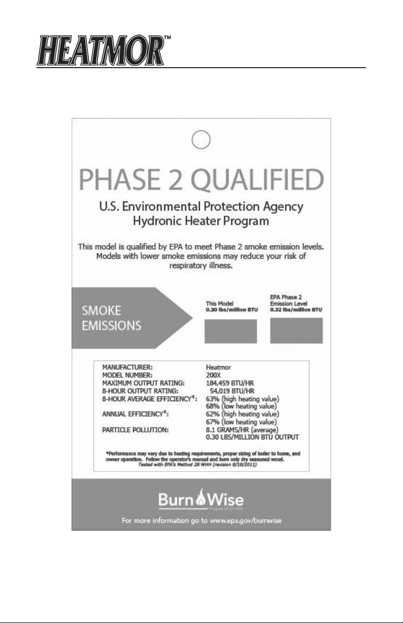
EPA PHASE 2 HANGTAG X-SERIES
2
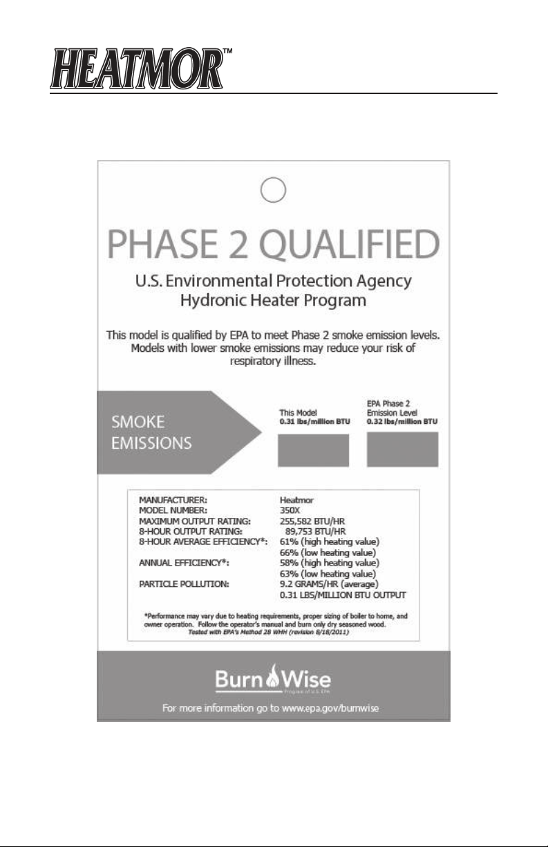
EPA PHASE 2 HANGTAG X-SERIES
3
Chapter 1
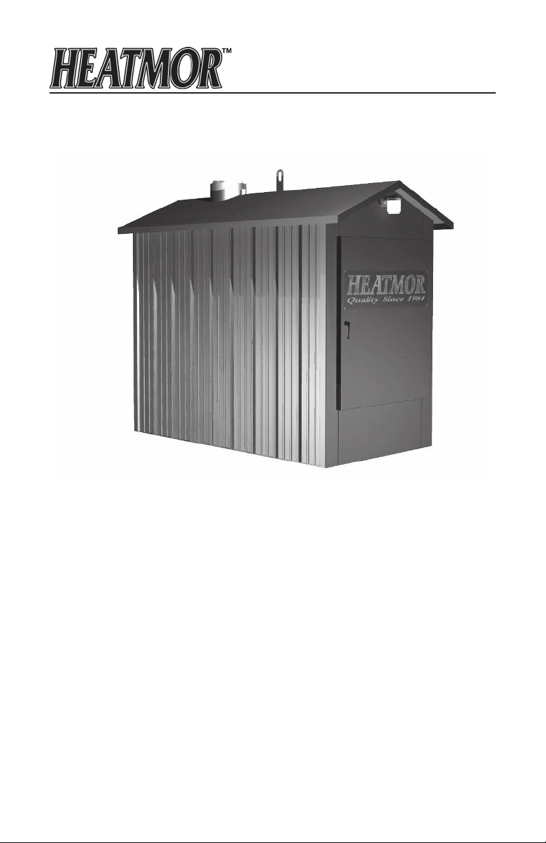
HEATMOR™ X-SERIES OUTDOOR FURNACE MODEL
Model 200X, 350X
5
RESIDENTIAL FURNACE SPECIFICATIONS
Specications Model 200X Model 350X
Overall Width
Base Width (Footprint)
50" 50"
46.5" 46.5"
Overall Height
Overall Length
Base Length (Footprint)
Total Weight (lbs, without water)
Water Capacity (U.S. gallons)
Forced Draft (C.F.M.)
Chimney Size
Maximum Wood Length
Insulated Heating Area*
1 Loading/day
2 Loading/day
Firebox Width
Firebox Length
Firebox Height
Volume of Firebox (Cu. Ft.)
Firebox Door Size (W x H)
Flue Transfer Area
BTU’s (maximum)**
Water Jacket Steel
Gauge
Firebox Steel
Gauge
Base Steel
Gauge
Base of Unit to Bottom of Loading Door
Warranty - Workmanship
Warranty - Corrosion
Approvals Test Standards UL 2523-2009
Hook-ups
Type of Fuel
Electrical Supply 115 V, 60HZ, 1
*This is an estimate only. Actual loadings per day may vary depending on structures heated, type of wood used, and climate.
**This value should only be used as an indication of the furnace’s heat recovery ability. Sustained outputs at this rate will
increase the loadings per day. Some types of wood may prevent the furnace from reaching this maximum output.
82.5" 82.5"
95" 95"
83.75" 83.75"
1,835 1980
310 270
150 2 x 150
8" 8"
19" 30"
2,500 sqft
5,000 sqft
23.75" 23.75"
24" 36"
27.5" 27.5"
14 21
20"x18" 20"x18"
39.75 sqft 39.75 sqft
200,000 280,000
409 Stainless 409 Stainless
10 10
409 Stainless 409 Stainless
10 10
409 Stainless 409 Stainless
14 14
24" 24"
Limited Lifetime Limited Lifetime
Limited Lifetime Limited Lifetime
CSA-B366.1-11
Back Back
Wood Wood
Phase
4,000 sqft
8,000 sqft
UL2523-2009
CSA-B366.1-11
115 V, 60HZ, 1
Phase
6
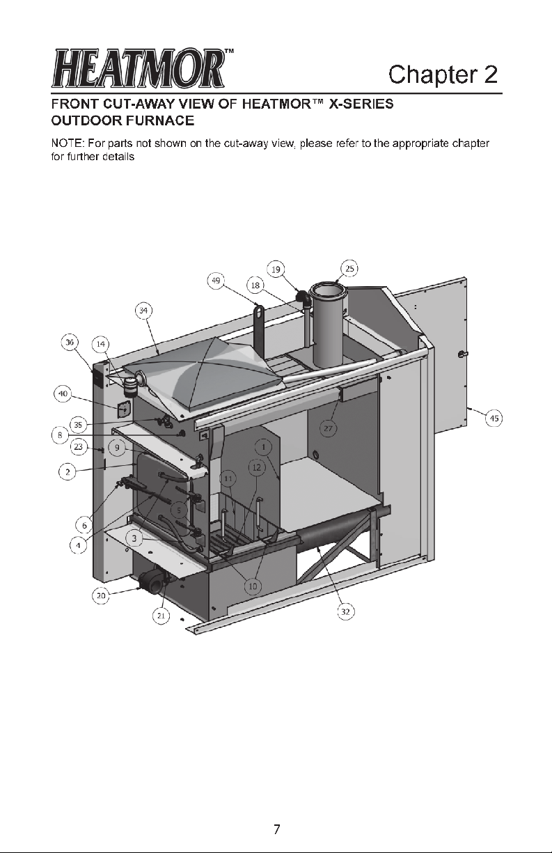

FURNACE PARTS LIST - FRONT CUT-AWAY OF X-SERIES
Firebox
1. Firebox
2. Firebox door
3. Firebox door hoses and elbows
4. Firebox door handle
5. Firebox door hinge
6. Firebox door latch
7. Firebox door handle holder
(not shown)
8. Firebox door gasket (not shown)
9. Firebox door frame
10. Firebox / base connector clamps
11. Firebrick
12. Standard grates
13. Sand (around ash pan)
50. Firebox heat shield (not shown)
Water Jacket
15. Water jacket (surrounds rebox)
16. Supply line threaded connector
(not shown)
17. Return line threaded connector
(not shown)
18. Relief vent pipe
19. Relief elbow
Ashes
30. Ash pan (under grates #12)
31. Ash auger (not shown)
32. Ash auger tube
33. Ash auger tube cover plate
(not shown)
Bladder assembly
34. Bladder
35. Bladder gate valve and hose
Electrical
14. Front Light
36. Electronic Controller
37. Electrical supply junction box
(not shown)
38. Electrical plug outlets (not shown)
39. Water temperature high-limit
controller (aquastat) (not shown)
40. Front light and combustion air
blower control switch
41. Temperature Probe (not shown)
42. Low Water Switch
(under Bladder)
Air Supply
20. Combustion air blower
21. Flipper assembly
22. Air box (not shown)
23. Automatic Fab Switch (A.F.S.)
Chimney and Top Flue
25. Chimney
26. Chimney extension(s)
(not shown)
27. Tube ue
28. Flue cover plate (not shown)
29. Flue scraper (not shown)
Housing - (not shown)
44. Outer front door
45. Outer rear door
46. Roof
47. Sides
48. Insulation
Lift Hook
49. Lift ring
8
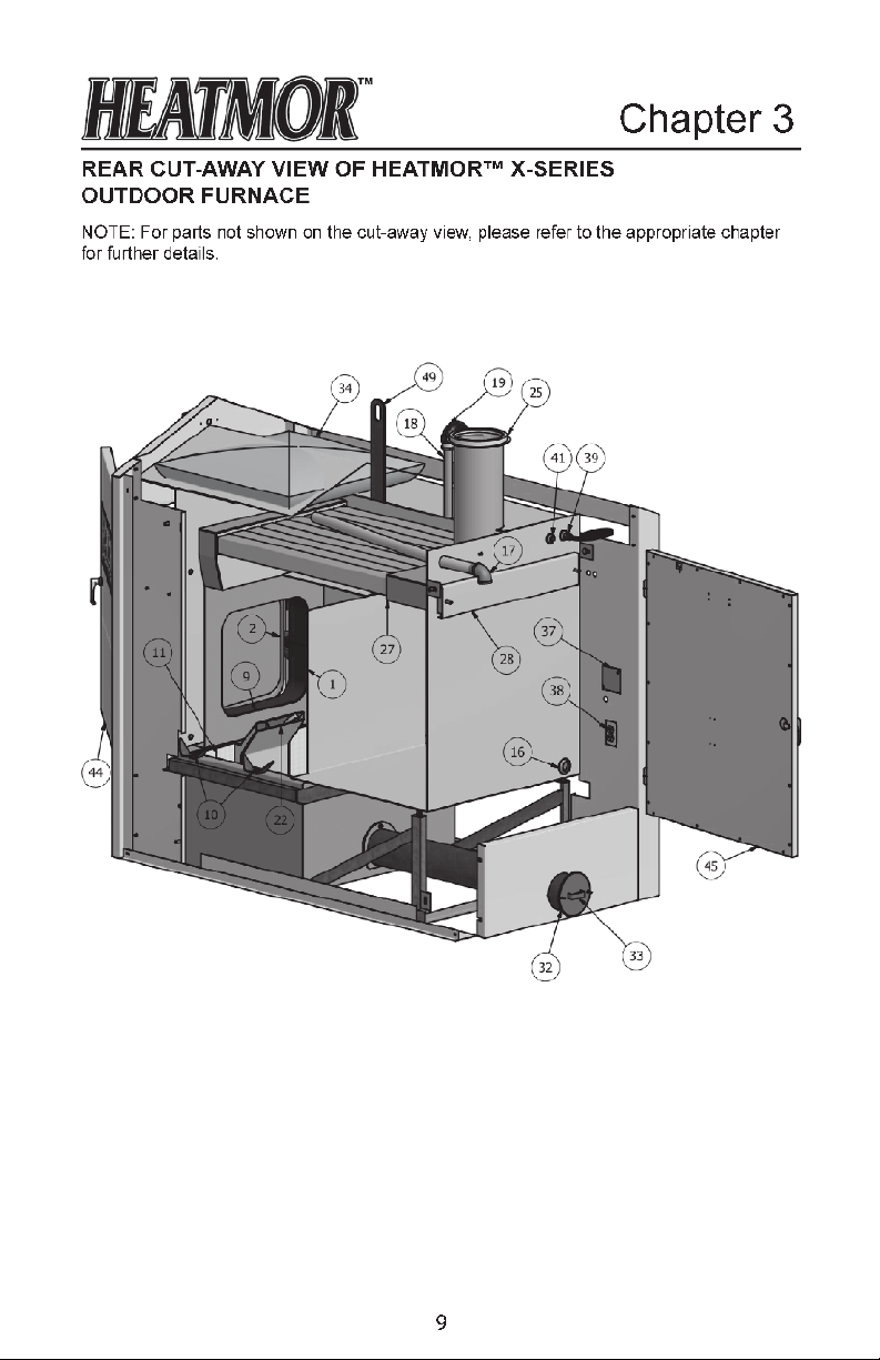

FURNACE PARTS LIST - REAR CUT-AWAY OF X-SERIES
Firebox
1. Firebox
2. Firebox door
3. Firebox door hoses and elbows
4. Firebox door handle (not shown)
5. Firebox door hinge (not shown)
6. Firebox door latch (not shown)
7. Firebox door handle holder (not
shown)
8. Firebox door gasket (not shown)
9. Firebox door frame
10. Firebox / base connector clamps
11. Firebrick
12. Standard grates (not shown)
13. Sand (around ash pan)
50. Firebox heat shield (not shown)
Water Jacket
15. Water jacket (surrounds rebox)
16. Supply line threaded connector
17. Return line threaded connector
18. Relief vent pipe
19. Relief elbow
Ashes
30. Ash pan (under grates #12)
31. Ash auger (not shown)
32. Ash auger tube
33. Ash auger tube cover plate
Bladder assembly
34. Bladder
35. Bladder gate valve and hose (not
shown)
Electrical
14. Front Light (not shown)
36. Electronic Controller (not shown)
37. Electrical supply junction box
38. Electrical plug outlets
39. Water temperature high-limit
controller (aquastat)
40. Front light and combustion air
blower control switch (not shown)
41. Temperature Probe
42. Low Water Switch (not shown)
Air Supply
20. Combustion air blower (not
shown)
21. Flipper assembly (not shown)
22. Air box
23. Automatic Fab Switch (A.F.S.)
(not shown)
Chimney and Top Flue
25. Chimney
26. Chimney extension(s) (not
shown)
27. Tube ue
28. Flue cover plate
29. Flue Ash Catcher (not shown)
Housing - (not shown)
44. Outer front door
45. Outer rear door
46. Roof
47. Sides
48. Insulation
Lift Hook
49. Lift ring
10

Chapter 4
MINIMUM CLEARANCE SEPARATION SPECIFICATIONS
The HEATMOR™ furnace, is certied to be installed outside, away from other buildings.
Please observe the following “Clearance to Combustibles” guidelines. If you have any further questions, which are not addressed in this Operators Manual, please contact your local
dealer for further information.
• To HEATMOR™ Stainless Steel Outdoor Furnace BACK. 96"
• To HEATMOR™ Stainless Steel Outdoor Furnace TOP 18"
• To HEATMOR™ Stainless Steel Outdoor Furnace FRONT 48"
• To HEATMOR™ Stainless Steel Outdoor Furnace Chimney 18"
• To HEATMOR™ Stainless Steel Outdoor Furnace Sides 6"
• DO NOT store combustible liquids or materials near the furnace
• It is not recommended to install the furnace in any form of building
Before installing your HEATMOR™ Stainless Steel Outdoor Furnace, if in the United
States, always check any and all applicable state and local regulations and inform your
insurance agent.
Before installing your HEATMOR™ Stainless Steel Outdoor Furnace, if in Canada, always
check any and all applicable Provincial and Municipal regulations and inform your insurance agent.
HEATMOR™ Inc. strongly recommends not installing a HEATMOR™ Stainless Steel Out-
door Furnace within 50 feet of any ammable structure.
A HEATMOR™ Stainless Steel Outdoor Furnace should be located with consideration to
your neighbor’s property and in accordance with local ordinances. Refer to the “Best Burn
Practices” for further operating considerations.
HEATMOR™ Outdoor Furnace, is not designed or certied to be located in densely populated areas.
11

Chapter 5
WARNINGS AND PRECAUTIONS
Please read the following list of cautions, warnings, and dangers before installing
and operating your HEATMOR™ STAINLESS STEEL OUTDOOR FURNACE. If you
have any questions or concerns regarding any of the following cautions, warnings,
dangers, or instructions in the Operations and Maintenance manual, please contact
your local dealer.
Familiarize yourself with the “Best Burn Practices” located on the inside front cover.
For more information go to http://www.epa.gov/burnwise/
Installation
Installation should be performed by a qualied installer and will comply with all the requirements of the authority having jurisdiction over the installation.
1. The HEATMOR™ furnace is designed for outside installations, away from other buildings.
2. Please observe the following “Clearance to Combustibles” guidelines.
To unit back = 96"
To unit front = 48"
To unit top = 18"
3. Before installing the furnace, always check any and all applicable state, provincial, and
local regulations.
4. HEATMOR™ Inc. strongly recommends not installing a HEATMOR™ Stainless Steel
Outdoor Furnace within 50’ of any ammable structure.
5. A HEATMOR™ Stainless Steel Outdoor Furnace should be located with consideration
to your neighbor’s property and in accordance with local ordinances. The
Outdoor Furnace is not designed to be located in densely populated areas.
6. HEATMOR™ suggests the use of brass ttings when installing the unit.
7. Before installing the HEATMOR™ furnace, contact and inform your insurance agent.
To unit sides = 6"
To chimney = 18"
HEATMOR™
8. The HEATMOR™ Outdoor Furnace is to be installed on a concrete base only. Any
attempt to place the furnace on any other surface may void the warranty.
9. Do not connect the HEATMOR™ furnace to the chimney of an existing heating system.
10. This unit was not designed, nor is it recommended, for use as a stand-alone heating
system. A back up source of heat must be in place to prevent the outdoor furnace from
freezing and to provide supplementary heat for the heated buildings.
11. Do not pressurize the HEATMOR™ Outdoor Furnace. This unit is designed to operate
under atmospheric pressure only.
12. Place the in-line ll/drain assembly in a location where the drained contents of the
HEATMOR™ will not cause damage to the surrounding areas or its content.
12
Electrical
1. Do not connect the electrical components of the HEATMOR™ Outdoor Furnace to any
other electrical appliance.
2. This HEATMOR™ Outdoor Furnace operates on 115-volt power only. Do not connect
the furnace to a 220-volt electrical supply.
3. HEATMOR™ Inc. recommends a licensed professional electrician make all the
necessary electrical connections involved with the installation of the furnace.
4. Always disconnect the HEATMOR™ Outdoor Furnace from the main electrical supply
before servicing any of the electrical components of the HEATMOR™ Outdoor Furnace.
5. Always disconnect any existing electrical connections to any in-house heating system,
before installing the outdoor furnace to any existing indoor heating system or appliances.
6. The red wire from the high-limit aquastat on the back of the HEATMOR™ should
be wired to a 120v indoor temperature control to override the thermostat. This will
dissipate excess heat in the event of a possible malfunction with the HEATMOR™.
The red wire is capped off in the electrical junction box when the HEATMOR™ is
new.
Other
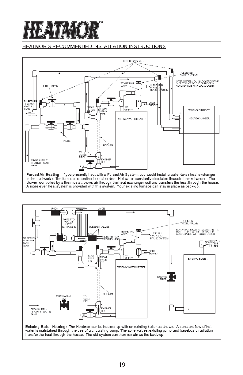
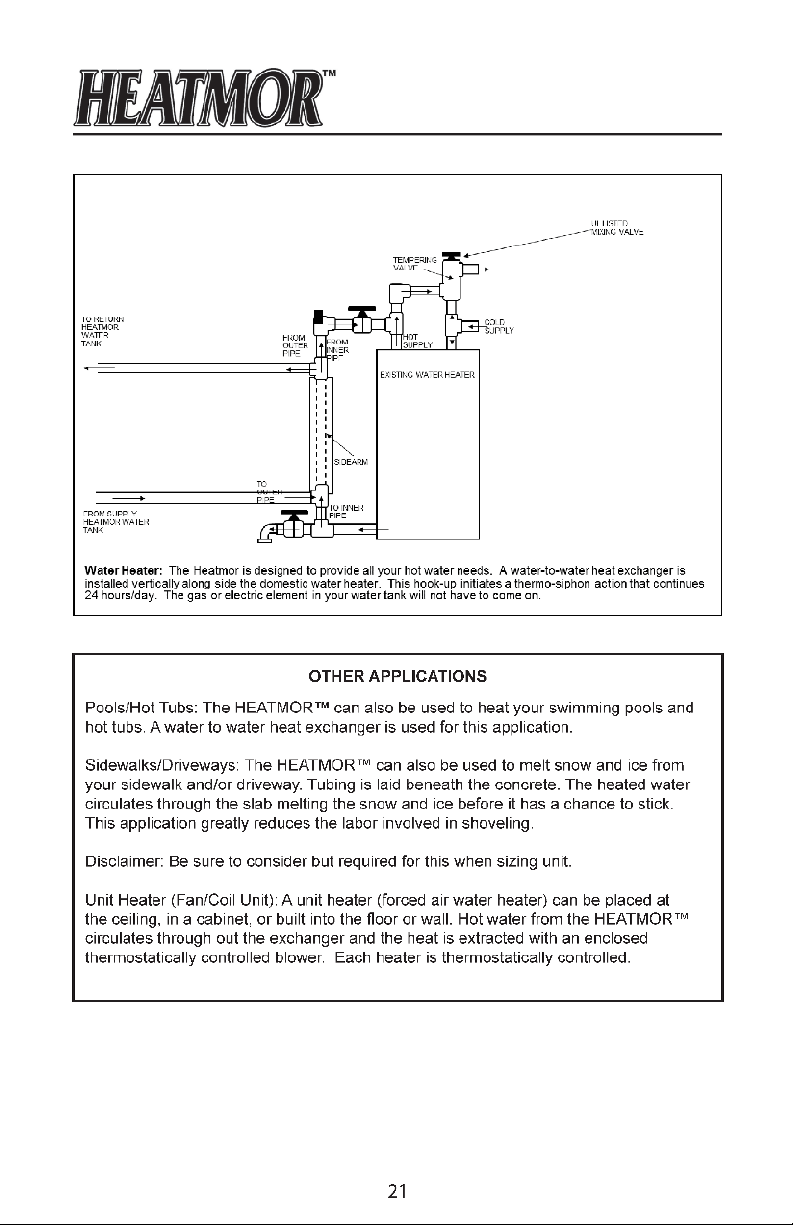
1. The unit may be connected to an existing indoor boiler system by installing a water-to-water heat exchanger.
2. HEATMOR™ INC. recommends that you contact a licensed professional plumber to
make all necessary plumbing installations between the HEATMOR™ furnace and the
existing heating system of your building(s).
3. Do not operate the HEATMOR™ furnace until all electrical and water line connections
have been properly installed and tested.
4. Do not allow any re in the rebox until the HEATMOR™ has the correct amount of
water and sand installed.
5. DO NOT OVER-FIRE THIS HEATER. Attempts to achieve heat output rates that ex-
ceed heater design specications can result in permanent damage to the heater and
to the catalytic combustor if so equipped.
13

X-Series Pad Specications
Chapter 6
The actual pad size is 50" x 88". This
gives approximately 2" extra on all sides of
furnace.
CAUTION: Do not exceed this length
measurement. Overall width may exceed
measurements if desired.
The bottom of the loading door is 24" above
ground or base of furnace. If you desire to
have the leading door higher, you can do so
by making the pad depth thicker.
Example: 12" instead of 4" or any gure in
between.
Patio stones or separate cement pad in
front of the loading door should NOT be
attached to main base of furnace.
It is recommended to use steel mesh or
rebar in pad for strength.
Benets to raising the pad:
1. Gives space below the ash auger
to place a pail for convenient ash
removal.
2. Allows better visibility of the rebox.
3. Less bending when adding wood.
4. Keeps exhaust above the operator.
5. Protects the base of the HEATMOR™
14

Chapter 7
INSTALLATION OF THE HEATMOR™ FURNACE
Installation should be performed by a qualied installer and will comply with all the requirements of the authority having jurisdiction over the installation.
Principles
1. Need to have an airtight seal between the concrete base and the perimeter of the
rebox base.
2. Need to seal the perimeter of the entire HEATMOR™ so rodents are not able to nd a
home inside the HEATMOR™.
3. Need to lift the HEATMOR™ without damaging it.
Equipment Required
1. It is NOT possible to lift a HEATMOR™ with the forks
of a forklift under the HEATMOR™. It MUST BE
LIFTED FROM THE TOP, by the lift hook. A crane or
heavy backhoe works best, although a heavy duty
farm tractor is acceptable.
a. With a farm tractor, extreme care must be taken
to prevent the HEAMTOR™ from swinging and
causing damage to the HEATMOR™.
Placing the HEATMOR™ on the Concrete Base
2. Before setting the HEATMOR™ onto the concrete
base, it is a good idea to place a solid sheet of the
proper “reective air foil” (also called bubble foil)
between the concrete and the HEATMOR™. This will
absorb ridges in the concrete and make it easier to
apply caulking around the inside perimeter of the base
of the HEATMOR™. This reective foil will also reect escaping heat up into the sand,
and help prevent air leaks into the rebox if cement cracks.
3. Make sure the total area of the base (where the sand is going) is on solid concrete. Do
not let the base extend past the hole in the concrete where the lines come in.
4. After the HEATMOR™ is in place perform the following:
Caulking around the Firebox Base
a. One person should get into the HEATMOR™.
b. Apply a substantial bead of caulking around the entire inside perimeter
of the base. This will give an airtight seal so no air will seep through the
sand. This should require about three tubes of High Temperature
Silicone.
Caulking around the Outside Perimeter of HEATMOR™
c. With a sharp knife, trim any excess bubble foil that extends past the
base of the HEATMOR™.
d. Apply a bead of caulking around the entire outside perimeter of the
HEATMOR™ to seal out rodents.
15
FILLING THE HEATMOR™ OUTDOOR FURNACE INITIALLY
WITH WATER
Before your HEATMOR™ furnace with water, all plumbing connections at the back of the
HEATMOR™ furnace, all electrical hookups, and all heating appliances should be installed
and tested for possible leaks.
HEATMOR™ suggests the use of brass ttings when installing the unit.
NOTE: If you have any questions regarding installation of the furnace or any aspect of
installation, contact your local dealer.
NOTE: Never start a re inside the rebox until the water jacket is full of water and sand
has been added to the base to the correct level.
1. Close the bladder gate valve located at the front of the HEATMOR™ furnace.
2. This valve will ensure no water can enter the bladder.
3. Close the bottom supply line valve at this back of the
HEATMOR™.
4. Open the top return line valve at the back of the
HEATMOR™.
5. Ensure the vent pipe is unobstructed. If equipped with a pop-
off ball on the roof of the furnace, remove it from the relief
vent pipe.
6. Connect the water source to the return line leading to the
HEATMOR™. Use a garden hose to add the water to the
return line.
7. Turn on the source of water.
8. The pressured water will now ow through and remove the
air out of the return line as the wter ows into the
HEATMOR™.
9. Continue adding water until water ows out the relief vent
pipe onto the roof of the HEATMOR™.
10. Turn off the source of water.
The HEATMOR™ is now full of water and the return line is also full of water and air free,
BUT the supply line leading from the HEATMOR™ to the building to be heated is still full
of air.
11. Close the top return line valve at the back of the HEATMOR™.
12. Remove the garden hose that was used to deliver the source of water from the top
return line, BUT leave the garden hose valve open.
13. Open the bottom supply line at the back of the HEATMOR™ (bottom). The pressure
of the water in the HEATMOR™ will now force water from the HEATMOR™ through
the supply line back into the building to be heated. This water will soon discharge
from where the garden hose was connected. When there is a steady stream of water
owing, the air will be removed from that supply line. Usually it requires the removal of
approximately ve gallons of water to ensure the line is air-free.
Bladder Gate Valve
16
FILLING THE HEATMOR™ OUTDOOR FURNACE INITIALLY
WITH WATER
NOTE: The circulator pumps cannot “push” much air through a system. They are designed
to move water not air.
14. Start the circulating pump. Remember to properly bleed air from the pump.
ABSOLUTELY NO FIRE IN THE FIREBOX WHEN PERFORMING THIS PROCEDURE.
DO NOT PERFORM THIS PROCEDURE WHEN UNIT WATER TEMPERATURE IS
UNSAFE. ALWAYS WEAR PERSONAL PROTECTIVE EQUIPMENT WHEN WORKING
Maintaining the Correct Amount of Water in the Bladder and in the HEATMOR™
1. Close the bladder gate valve located at the front of the HEATMOR™ furnace. Closing
this valve will ensure no water can enter the bladder.
2. Remove the pop-off ball (if equipped) from the relief vent pipe.
3. Connect the water source to the return line leading to the HEATMOR™. Use a garden
hose to add the water to the return line.
4. Turn on the source of water, but only about half a full ow.
5. The pressured water will now ow through the return line as the water ows into the
HEATMOR™.
6. Continue adding water until water ows out the relief vent pipe, onto the roof of the
HEATMOR™, leave the water running. Some may continue to spill out onto the roof.
7. Place the pop-off ball (if equipped) back onto the relief vent pipe.
8. Turn on the green bladder gate valve and let the bladder ll half full. You can check
this by felling the bladder with your hand inserted through the bladder inspection cover
plate.
9. Turn off the water when the bladder is half full.
Low Water Condition
If the water level is below the bladder port when the water heats up, air will enter the
bladder instead of water. To remove the air from the bladder, follow steps 1 through 7 above
and make sure there is a good seal on the pop-off ball (if equipped). Next:
1. Open the bladder gate valve.
2. CAREFULLY remove the bladder hose, allowing the bladder to empty its contents.
3. After bladder is empty of air/water, re-attach the bladder hose to the bladder gate
valve and tighten the hose clamp.
WITH WATER AND CHEMICALS.
Next, follow steps 7-9 above.
NOTE: Never light a re inside the rebox until the water jacket is full of water and sand
has been added to the base to the correct level.
Installation should be performed by a qualied installer and will comply with all the requirements of the authority having jurisdiction over the installation.
READ THROUGH THE ENTIRE OPERATIONS AND MAINTENANCE MANUAL BEFORE
OPERATING YOUR HEATMOR™ STAINLESS STEEL OUTDOOR FURNACE.
17
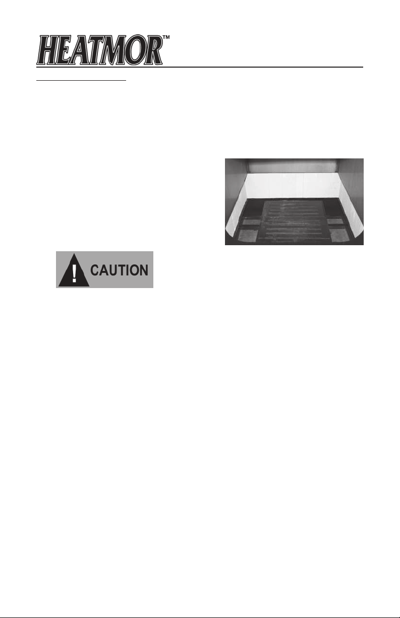
Initial Installation of Sand
Types of Sand to Use
1. Sand that does not contain clay, rocks or organic matter is appropriate. Use a sand
that when packed will not allow air to pass through. Mortar sand or sand that is used in
the redi-mix concrete business is good. Never use gravel.
2. 200X requires approximately 0.18 cubic yards.
3. 350X requires approximately 0.28 cubic yards.
Installation
1. Cover the grates with a piece of cardboard.
2. One person enters the rebox.
3. Another person shovels the sand into the
rebox while the person inside packs the sand
completely, using a piece of wood like a 2" x 4"
x10" long.
4. Fill the base with sand, level to the top of the
grates.
Open Bottom without Sand
NOTE: Never light a re inside the rebox until the water jacket is full of water and sand
has been added to the correct level in the base.
18

Chapter 8
SAFE FURNACE OPERATION GUIDELINES
OPERATION
DO NOT USE CHEMICALS OR FLUIDS TO START THE
FIRE DO NOT BURN GARBAGE, GASOLINE, NAPHTHA,
ENGINE OIL, OR OTHER INAPPROPRIATE MATERIALS.
HEATMOR™ OUTDOOR FURNACES X-SERIES ARE CERTIFIED TO BURN WOOD
ONLY.
Burning of other materials may result in serious burns, health consequences, or damage to
this furnace and other components of the heating system and may void warranty.
***IMPORTANT NOTICE***
PLEASE REFER TO “FILLING YOUR HEATMOR™ FURNACE WITH WOOD”,
FOR ADDITIONAL SAFE LOADING PROCEDURES.
1. Never open the rebox door if the combustion air blower is operating or if you suspect
a roaring hot re inside the rebox.
2. Never open rebox door immediately after the combustion air blowers have shut off.
If the water temperature is very close to the high setting, you should assume the air
combustion fans have just shut off.
3. If there is more than a ‘whiff’ of exhaust coming from the chimney and the draft fan is
off, do not open the rebox door for at least two minutes. The burn cycle would heave
just ended and the rebox will be full of unburned gases (exhaust) that may ignite
when fresh air is introduced.
4. Load the unit with wood carefully, but quickly. After loading wood make sure all debris
is cleaned from the rebox door frame and gasket. Then close rebox door securely.
5. Keep the rebox door, ash auger tube cover cap, top ue cover plate, and the outer
door of the HEATMOR™ furnace closed at all times except for servicing and refueling.
6. Keep the locking handle on the outer door locked at all times when not servicing or
refueling to reduce the risk of tampering and possible injury.
7. Never add water to the HEATMOR™ furnace if the internal water temperature is over
212˚ Fahrenheit. Failure to adhere to this warning may cause a steam ash and result
in an explosion.
8. Do not store combustible liquids or materials near the outdoor furnace. Adhere to the
“Clearance to Combustibles” guildelines.
9. Never use gasoline, kerosene, charcoal, lighter uid or similar liquids to start, restart
or freshen up a re. Using such liquids may result in severe burns and injures.
10. When adding water, water treatment or maintaining the HEATMOR™ furnace,
protective clothing must be worn at all times.
11. Never leave the HEATMOR™ furnace unattended while the rebox door is open or
unlatched.
12. Stay clear of any exhaust emitting from the rebox.
13. Do not burn garbage, plastics, rubber naphtha, trash, tires, solvents, engine oil,
gasoline, leaves, paper products, cardboard, material treated with petroleum products
(particleboard, railroad ties and pressure treated wood) or other inappropriate
materials.
22
 Loading...