

Heatmor 100 CSS, 200 CSS, 400 DCSS Instructions For Use Manual
Outdoor Furnaces
TM
SAVE THESE INSTRUCTIONS
When these safety symbols appear on the following pages, they will
alert you to the possibility of serious injury if you do not comply with the
corresponding instructions. The hazard may originate from something
mechanical or electrical shock. Please read the instructions carefully.
When you see this safety symbol on the following pages, it will alert you
TM
to the possibility of damage to your HEATMOR
Stainless Steel Outdoor
Furnace if you do not comply with the corresponding instructions. Please
read the instructions carefully.
TM
The HEATMOR
Stainless Steel Outdoor Furnace is certied to offer safe
service provided it is installed, operated and maintained in accordance with
the instructions contained in this manual.
Proper personal protective equipment, (PPE), MUST BE WORN AT ALL
TIMES when servicing and maintaining any of the HEATMOR
Steel Outdoor Furnace product line.
ii
TM
Stainless

TABLE OF CONTENTS Page #
I DEAR HEATMOR™ OWNER 1
II NOTICE TO THE READER 2
III CERTIFICATE OF COMPLIANCE 3,4
1 HEATMOR™ STAINLESS STEEL FURNACE MODELS 5
2 FURNACE SPECIFICATIONS 6
3 FRONT CUT AWAY VIEW OF HEATMOR™ OUTDOOR FURNACE 7
FURNACE PARTS LIST 8
4 REAR CUT AWAY VIEW OF HEATMOR™ OUTDOOR FURNACE 9
FURNACE PARTS LIST 10
5 MINIMUM CLEARANCE SEPARATION SPECIFICATIONS 11
6 WARNINGS AND PRECAUTIONS 12
A Installation 12
B Electrical 13
C Other 13
7 CONCRETE PAD SPECIFICATIONS 14-16
8 INSTALLATION OF THE HEATMOR™ FURNACE 17
A Equipment Required 17
B Placing the HEATMOR™ on the Concrete Pad 17
C Caulking Around the Firebox Base 17
D Caulking Around the Outside Perimeter of HEATMOR™ 17
E Filling the HEATMOR™ Outdoor Furnace Initially with Water 18
F Maintaining Water in the Bladder and in the HEATMOR™ 19
G Initial Installation of Sand 20
i. Types of sand to use 20
ii. Installation 20
9 SAFE OPERATING GUIDELINES 21
A Operation 21
B Lighting Your HEATMOR™ for the First Time 23
C Dew Point 24
D Loading Wood into the HEATMOR™ 25
E What can I burn? 26
F How does a fire burn out? 26
G Types of Wood 27
H Wood as a Fuel 27
I Stages of Combustion 27
J Efficiency Measurements and Types of Fires 28
K Types of Fires 28
L Handling and Storage of Wood 29
M Types of Coal 30
N Coal as a Fuel 30
i. Wood 26
iii

O Handling and Storage of Coal 30
P Loading Coal into the HEATMOR™ 30
10 WATER 31
A Qualities of Water to Use 31
B Water Level Maintenance 31
C Removal of water and replacement of water 31
D Water Additives 32
E Water Treatment Additives and Safety Specifications 33
F Adding Water Treatment and Freeze Protection Products 34
11 BLADDER ASSEMBLY 36
A Bladder 36
B Bladder Gate Valve and Bladder Hose 37
C Water Level Gauge 38
D Bladder Cover Plate 38
12 WATER JACKET 39
A Water Jacket 39
B Supply Line and Return Line Connectors 39
C Relief Vent Pipe and Weighted Pop off Ball 39
13 FIREBOX AND OTHER COMPONENTS 40
A Firebox 40
B Firebox Door 41
C Firebox Door Hoses and Elbows 43
D Firebox Door Handle 44
E Firebox Door Hinge 44
F Firebox Door Latch 44
G Firebox Door Holder 45
H Firebox Door Gasket 45
I Firebox Door Frame 46
J Firebox / Base Connector Clamps 46
K Firebrick 47
L Standard Grates 47
M Optional Shaker Grates 48
N Sand 49
i. Types of sand to use 49
ii. Installation 49
O Flash Curtain / Heat Shield 50
14 AIR SUPPLY 51
A Combustion Air Blower and Flipper Assembly 51
i. Operation of the Combustion Air Blower and Flipper Assembly 51
ii. Steps to Maintain your Blower / Flipper Assembly 51
B Air Box(s) 52
C Combustion Air Percentage Tube 53
D Automatic Fan Switch (A.F.S.) 53
iv

15 CHIMNEY AND TOP FLUE 54
A Chimney 54
B Chimney Extension(s) 54
C Flue 55
D Top Flue Cover 55
E Flue Scraper 55
16 ASHES 56
A Ash Management and Ash Removal 56
B Ash Pan 57
C Ash Auger 57
D Ash Auger Tube 57
E Ash Auger Tube Cover Plate 58
17 THERMOMETER (TEMPERATURE GAUGE) 59
18 ELECTRICAL
A Electrical Supply 60
B Electrical Supply Junction Box 60
C Double Electrical Outlets at rear 61
D Water Temperature Range Control (Aquastat on the left) 61
E High Water Temperature Safety Shutoff Controller (Aquastat on the right) 62
F Front Light and Fan Power Switch 63
G In The Event of a Power Failure 64
60
19 EXTERIOR CLADDING AND INSULATION 65
A Outer Door of HEATMOR™ 65
B Roof of the HEATMOR™ 65
C Sides of the HEATMOR™ 66
D Insulation 66
20 AIR LEAKS 67
A Checking For Air Leaks 67
B Why do we not want any air leaks? 67
21 WATER LEAKS 68
22 DOMESTIC COIL
69
23 SEASON START UP & SHUT DOWN CHECKLISTS 70
24 FREQUENTLY ASKED QUESTIONS
73
25 TROUBLESHOOTING AND SOLUTIONS
HEATMOR™ STAINLESS STEEL LIMITED WARRANTY
HEATMOR™ FOR LIFE
NOTES
75
88
91
92
v

Dear HEATMOR™ Owner,
On behalf of myself and the employees of HEATMOR™, I would like to take this opportunity to personally
thank you for the purchase of our HEATMOR™ Stainless Steel Outdoor Furnace. You can be assured that
your HEATMOR™ was constructed with great emphasis on quality and workmanship. It is our commitment to
provide you with the finest outdoor furnace in the industry. We wish you many years of trouble-free use and we
sincerely hope you enjoy the comforts of burning wood.
This manual contains the manufacturer’s recommendations for operation and maintenance of the HEATMOR™
Stainless Steel Outdoor Furnace. Also included are some regular maintenance tips and FAQ’s (frequently
asked questions). Please observe and follow all safety instructions as directed in this manual. SAVE THESE
INSTRUCTIONS FOR FUTURE REFERENCE.
Finally, please fill out your registration and warranty forms, if you haven’t done so already. If you have any
further questions on the operation or maintenance of your HEATMOR™ Outdoor Furnace, please contact your
local dealer.
Sincerely,
Gerry Reed,
President
1

NOTICE TO THE READER
HEATMOR™ Inc. warrants and guarantees ALL HEATMOR™ Stainless Steel Outdoor Furnace Models.
HEATMOR™ Inc. does not warrant or guarantee any of the supporting products described within this
Operations and Maintenance Manual.
The contents, descriptions, directions, diagrams, and recommendations within this material are for the sole
purpose of suggested operation and maintenance methods.
Furthermore, HEATMOR™ Inc. shall not be liable for any special, consequential, or exemplary damages,
resulting, in whole or part, from the readers’ neglectful use, based upon the material within this Operations and
Maintenance Manual. Adhere to and follow all maintenance procedures set forth in this manual.
The methods of operation described within this Operations and Maintenance Manual have proven to be
effective for HEATMOR™ Inc. for the sole purpose of the operation of a HEATMOR™ Stainless Steel Outdoor
Furnace.
All formulas and gures listed within this Operations and Maintenance Manual are approximated and should be
read as such.
For additional copies or information, contact
HEATMOR™ Inc.
105 Industrial Park Court NE,
P.O. Box 787,
Warroad, MN 56763 USA
Phone: (218) 386-2769
Fax: (218) 386-2947
Website: www.heatmor.com
E-mail: woodheat@heatmor.com
Copyright © 2012- HEATMOR™ INC.
All rights reserved. No part of this Operations and Maintenance Manual may be reproduced or used in any
form or by any means - graphic, electronic or mechanical, including photocopying, recording, taping, or
information storage and retrieval systems - without the written permission of HEATMOR™ Inc.
MODELS (100 CSS, 200 CSS, 400 DCSS)
Supplemental literature will be provided in addition to this manual for Models 200 CSS/OB, 400 DCSS/OB, 600
CSS and 800 CSS.
2

Units are Safety Listed by Omni Test Laboratories
Report # 275-O-11-4 and # 275-O-12-4
Listed to UL2523-2009 and CSA B366.1-11
3

Units are Safety Listed by Omni Test Laboratories
Report # 275-O-11-4 and # 275-O-12-4
Listed to UL2523-2009 and CSA B366.1-11
4
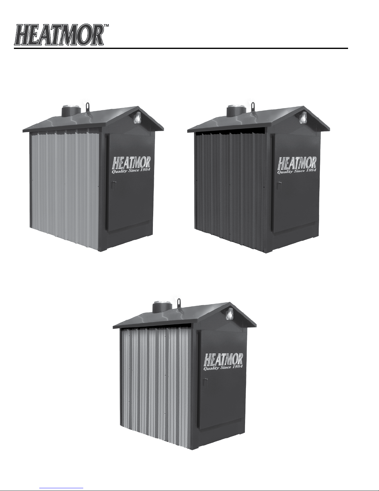
CHAPTER 1
HEATMOR™ STAINLESS STEEL OUTDOOR FURNACE MODELS
Model 100 CSS
Model 200 CSS
5
Model 400 DCSS

CHAPTER 2
RESIDENTIAL FURNACE SPECIFICATIONS
Specications Model 100 CSS Model 200 CSS Model 400 DCSS
Overall Width (Inches)
Base Width (Inches) (Footprint)
Overall Height (Inches)
(With chimney stub)
Overall Length (Inches)
Base Length (Inches) (Footprint)
Total Weight (lbs., without water) 1375 1599 1968
Water Capacity (U.S. gallons) 85 114 155
Forced Draft (C.F.M.) 75 150 2 x 150 = 300
Chimney Size (Inches) 8 8 8
Wood Length (Inches) 24 36 54
Insulated Heating Area (Sq. Ft.)*
1 Loading/day
2 Loading/day
Firebox Width (Inches) 28 28 28
Firebox Length (Inches) 24 36 54
Firebox Height (Inches) 42 42 42
Volume of Firebox (Cu. Ft.) 14 21 32
Firebox Door Size (Inches) (W x H) 20 x 18 20 x 18 20 x 18
Flue Transfer Area (Sq. Ft.) 6.5 10 15
BTU’s (maximum)** 100,000 200,000 400,000
Water Jacket Steel
Gauge
Firebox Steel
Gauge
Base Steel
Gauge
Base of Unit to
Bottom of Loading Door (Inches)
Warranty - Workmanship
50
46.5
82.5 82.5 82.5
65
53.75
1500
3000
409 Stainless
10
409 Stainless
10
409 Stainless
14
24 24 24
Limited Lifetime Limited Lifetime Limited Lifetime
50
46.5
77
65.75
2500
5000
409 Stainless
10
409 Stainless
10
409 Stainless
14
50
46.5
95
83.75
5000
10,000
409 Stainless
10
409 Stainless
10
409 Stainless
14
Warranty - Corrosion
Approvals Test Standards UL Subject 2523 UL Subject 2523 UL Subject 2523
Hook-ups Back Back Back
Total Heat Extraction Area (Sq. Ft.) 30.89 40.89 55.89
Type of Fuel Wood and Coal Only Wood and Coal Only Wood and Coal Only
Electrical Supply 115 V, 60HZ, 1 Phase 115 V, 60HZ, 1 Phase 115 V, 60HZ, 1 Phase
* This is an estimate only. Actual loadings per day may vary depending on structures heated and type of wood used.
** This value should only be used as an indication of the furnace’s heat recovery ability. Sustained outputs at this rate will increase the
loadings per day. Some types of wood may prevent the furnace from reaching this maximum output.
Limited Lifetime Limited Lifetime Limited Lifetime
6
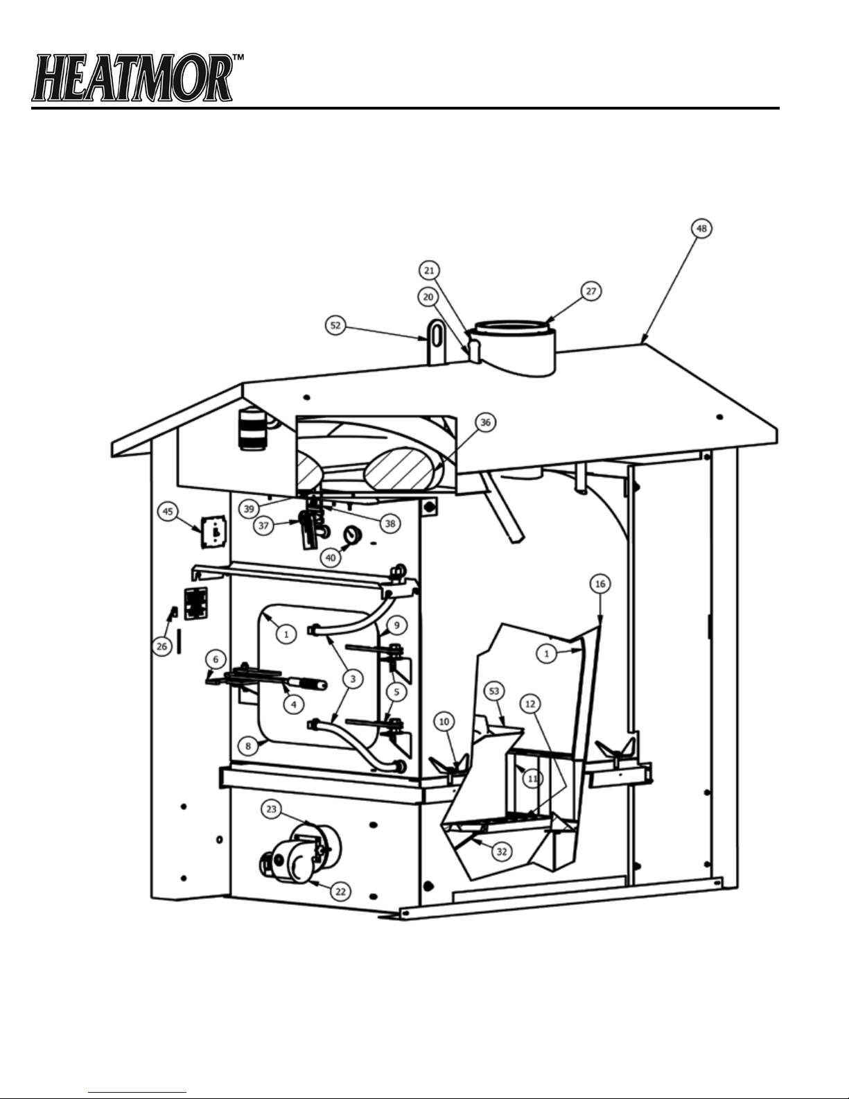
CHAPTER 3
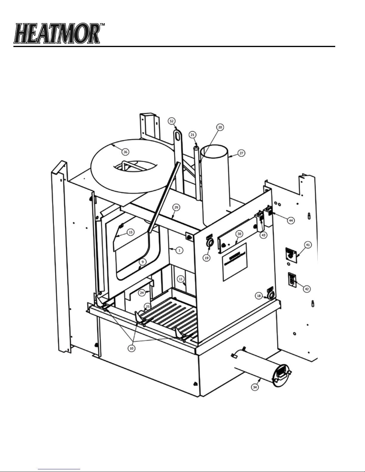
FRONT CUT-AWAY VIEW OF HEATMOR™ OUTDOOR FURNACE
(For parts not shown on the cut-away view, please refer to the appropriate chapter for further details.)
7

FURNACE PARTS LIST
Firebox
1) Firebox
2) Firebox door
3) Firebox door hoses and elbows
4) Firebox door handle
5) Firebox door hinge
6) Firebox door latch
7) Firebox door handle holder(not shown)
8) Firebox door gasket
9) Firebox door frame
10) Firebox / base connector clamps
11) Firebrick
12) Standard grates
13) Optional shaker grates(not shown)
14) Sand(not shown)
15) Flash curtain / heat shield(next page)
Water jacket
16) Water jacket (surrounds rebox)
18) Supply line threaded connector(next page)
19) Return line threaded connector(next page)
20) Relief vent pipe
21) Weighted pop off valve
Air supply
22) Combustion air blower (400 DCSS - 2 Fans)
23) Flipper assembly
24) Air box(s)(next page)
25) Combustion air percentage tube(next page)
26) Automatic Fan Switch (A.F.S.)
Chimney and top flue
27) Chimney Stub
28) Chimney extension(s)(not shown)
29) Top rectangular ue(next page)
30) Top ue cover plate(next page)
31) Top ue scraper(not shown)
Ashes
32) Ash pan
33) Ash auger(not shown)
34) Ash auger tube(next page)
35) Ash auger tube cover plate(next page)
Bladder assembly
36) Bladder
37) Bladder gate valve and hose
38) Water level gauge
39) Bladder inspection cover plate
Thermometer
40) Thermometer
Electrical
41) Electrical supply junction box(next page)
42) Electrical plug outlets(next page)
43) Water temperature controller
(aquastat) (next page)
44) Water temperature high-limit
controller (aquastat) (next page)
45) Front light and combustion air
blower control switch
Housing
46) Outer front door(not shown)
47) Outer rear door(not shown)
48) Roof
49) Sides(not shown)
50) Insulation(not shown)
Optional hot water internal coil
51) Internal coil(not shown)
Lift hook
52) Lift ring
53) Box of Chemical, Keys, Manual
8
CHAPTER 4
REAR CUT-AWAY VIEW OF HEATMOR™ OUTDOOR FURNACE
(For parts not shown on the cut-away view, please refer to the appropriate chapter for further details.)
9

FURNACE PARTS LIST
Firebox
1) Firebox
2) Firebox door
3) Firebox door hoses and elbows
4) Firebox door handle
5) Firebox door hinge
6) Firebox door latch
7) Firebox door handle holder(not shown)
8) Firebox door gasket
9) Firebox door frame
10) Firebox / base connector clamps
11) Firebrick
12) Standard grates
13) Optional shaker grates(not shown)
14) Sand(not shown)
15) Flash curtain / heat shield
Water jacket
16) Water jacket (surrounds rebox)
18) Supply line threaded connector
19) Return line threaded connector
20) Relief vent pipe
21) Weighted pop off valve
Air supply
22) Combustion air blower (400 DCSS - 2 Fans)
23) Flipper assembly
24) Air box(s)
25) Combustion air percentage tube
26) Automatic Fan Switch (A.F.S.)
Chimney and top flue
27) Chimney Stub
28) Chimney extension(s)(not shown)
29) Top rectangular ue
30) Top ue cover plate
31) Top ue scraper(not shown)
Ashes
32) Ash pan
33) Ash auger(not shown)
34) Ash auger tube
35) Ash auger tube cover plate
Bladder assembly
36) Bladder
37) Bladder gate valve and hose
38) Water level gauge
39) Bladder inspection cover plate
Thermometer
40) Thermometer
Electrical
41) Electrical supply junction box
42) Electrical plug outlets
43) Water temperature controller
(aquastat)
44) Water temperature high-limit
controller (aquastat)
45) Front light and combustion air
blower control switch
Housing
46) Outer front door(not shown)
47) Outer rear door(not shown)
48) Roof
49) Sides(not shown)
50) Insulation(not shown)
Optional hot water internal coil
51) Internal coil(not shown)
Lift hook
52) Lift ring
53) Box of Chemical, Keys, Manual
10

MINIMUM CLEARANCE SEPARATION SPECIFICATIONS
CHAPTER 5
The HEATMOR™ furnace, is certified to be installed outside, away from other buildings. Please observe the
following “Clearance to Combustibles” guidelines. If you have any further questions, which are not addressed
in this Operators Manual, please contact your local dealer for further information.
♦ To HEATMOR™ Stainless Steel Outdoor Furnace Back. 96 Inches
♦ To HEATMOR™ Stainless Steel Outdoor Furnace Top. 18 Inches
♦ To HEATMOR™ Stainless Steel Outdoor Furnace Front. 48 Inches
♦ To HEATMOR™ Stainless Steel Outdoor Furnace Chimney. 96 Inches
♦ To HEATMOR™ Stainless Steel Outdoor Furnace Sides. 6 Inches
♦ Do not store combustible liquids or materials near the furnace.
♦ It is not recommended to install the furnace in any form of building.
Before installing your HEATMOR™ Stainless Steel Outdoor Furnace, if in the United States, always check
any and all applicable state and local regulations and inform your insurance agent.
Before installing your HEATMOR™ Stainless Steel Outdoor Furnace, if in Canada, always check any and all
applicable Provincial and Municipal regulations and inform your insurance agent.
HEATMOR™ Inc. strongly recommends not installing a HEATMOR™ Stainless Steel Outdoor Furnace within
50 feet of any flammable structure.
A HEATMOR™ Stainless Steel Outdoor Furnace should be located with consideration to your neighbor’s
property and in accordance with local ordinances. Refer to the “Best Burn Practices” for further operating
considerations.
HEATMOR™ Outdoor Furnaces, Model 100 CSS, 200 CSS and 400 DCSS are not designed or certified to be
located in densely populated areas.
11
CHAPTER 6
CHAPTER 6
WARNINGS AND PRECAUTIONS
WARNINGS AND PRECAUTIONS
Please read the following list of cautions, warnings and dangers before installing and operating
Please read the following list of cautions, warnings and dangers before installing and operating
your HEATMOR™ STAINLESS STEEL OUTDOOR FURNACE. If you have any questions or concerns
your HEATMOR™ STAINLESS STEEL OUTDOOR FURNACE. If you have any questions or concerns
regarding any of the following cautions, warnings, dangers or instructions in this Operations and
regarding any of the following cautions, warnings, dangers or instructions in this Operations and
Maintenance manual, please contact your local dealer.
Maintenance manual, please contact your local dealer.
Familiarize yourself with the “Best Burn Practices” located on the inside front cover.
Familiarize yourself with the “Best Burn Practices” located on the inside front cover.
Installation
Installation
Installation should be performed by a qualied installer and will comply with all the requirements of
If you are installing parts of this heating system on a “do-it-yourself” basis, it is highly recommended
If you are installing parts of this heating system on a “do-it-yourself” basis, it is highly recommended
the authority having jurisdiction over the installation.
that you purchase a total system installation manual recommended by your dealer.
that you purchase a total system installation manual recommended by your dealer.
1) The HEATMOR™ furnace is designed for outside installations, away from other buildings.
1) The HEATMOR™ furnace is designed for outside installations, away from other buildings.
2) Please observe the following “ Clearance to Combustibles “ guidelines.
2) Please observe the following “ Clearance to Combustibles “ guidelines.
To unit back = 96 inches To unit sides = 6 inches
To unit back = 96 inches To unit sides = 6 inches
To unit front = 48 inches To chimney = 96 inches
To unit front = 48 inches To chimney = 96 inches
To unit top = 18 inches
3) Before installing the furnace, always check any and all applicable state, provincial, and local
regulations.
3) Before installing the furnace, always check any and all applicable state, provincial, and local
4) HEATMOR™ Inc. strongly recommends not installing a HEATMOR™ Stainless Steel Outdoor
regulations.
Furnace within 50 feet of any ammable structure.
4) HEATMOR™ Inc. strongly recommends not installing a HEATMOR™ Stainless Steel Outdoor
5) A HEATMOR™ Stainless Steel Outdoor Furnace should be located with consideration
Furnace within 50 feet of any flammable structure.
to your neighbor’s property and in accordance with local ordinances. HEATMOR™ Outdoor
5) A HEATMOR™ Stainless Steel Outdoor Furnace should be located with consideration
Furnaces, Model 100 CSS, 200 CSS and Model 400 DCSS, are not designed to be located
to your neighbor’s property and in accordance with local ordinances. HEATMOR™ Outdoor
in densely populated areas.
Furnaces, Model 100 CSS, 200 CSS and Model 400 DCSS, are not designed to be located
6) HEATMOR™ suggests the use of brass ttings when installing the unit.
in densely populated areas.
7) Before installing the HEATMOR™ furnace, contact and inform your insurance agent.
6) HEATMOR™ suggests the use of brass fittings when installing the unit.
7) Before installing the HEATMOR™ furnace, contact and inform your insurance agent.
8) The HEATMOR™ Outdoor Furnace is to be installed on a concrete base only. Any attempt to place
the furnace on any other surface may void the warranty.
8) The HEATMOR™ Outdoor Furnace is to be installed on a concrete base only. Any attempt to place
9) Do not connect the HEATMOR™ furnace to the chimney of any existing heating system.
the furnace on any other surface may void the warranty.
10) This unit was not designed, nor is it recommended, for use as a stand-alone heating system. A back
9) Do not connect the HEATMOR™ furnace to the chimney of any existing heating system.
up source of heat must be in place to prevent the outdoor furnace from freezing and to provide
10) This unit was not designed, nor is it recommended, for use as a stand-alone heating system. A back
supplementary heat for the heated buildings.
up source of heat must be in place to prevent the outdoor furnace from freezing and to provide
11) Do not pressurize the HEATMOR™ Outdoor Furnace. This unit is designed to operate under
supplementary heat for the heated buildings.
atmospheric pressure only.
11) Do not pressurize the HEATMOR™ Outdoor Furnace. This unit is designed to operate under
12) Place the in-line ll/drain assembly in a location where the drained contents of the HEATMOR™ will
atmospheric pressure only.
not cause damage to the surrounding areas or it’s contents.
12) Place the in-line fill/drain assembly in a location where the drained contents of the HEATMOR™ will
not cause damage to the surrounding areas or it’s contents.
12
CHAPTER 6
Electrical
1) Do not connect the electrical components of the HEATMOR™ Outdoor Furnace to any other
electrical appliance.
2) This HEATMOR™ Outdoor Furnace operates on 115-volt power only. Do not connect the furnace to a 220-
volt electrical supply.
3) HEATMOR™ INC. recommends a licensed professional electrician make all the necessary
electrical connections involved with the installation of the furnace.
4) Always disconnect the HEATMOR™ Outdoor Furnace from the main electrical supply before
servicing any of the electrical components of the HEATMOR™ Outdoor Furnace.
5) Always disconnect any existing electrical connections to any in-house heating system, before
installing the outdoor furnace to any existing indoor heating system or appliances.
6) The red wire from the high-limit aquastat on the back of the HEATMOR™ should be wired to the
indoor temperature control to override the thermostat. This will dissipate excess heat in the event of a
possible malfunction with the HEATMOR™. (The red wire is capped off in the electrical junction
box when the HEATMOR™ is new.)
Other
1) The unit may be connected to an existing indoor boiler system by installing a water-to-water heat
exchanger.
1) HEATMOR™ INC. recommends that you contact a licensed professional plumber to make
all necessary plumbing installations between the HEATMOR™ furnace and the existing heating
system of your building(s).
2) Do not operate the HEATMOR™ furnace until all electrical and water line connections have
been properly installed and tested.
3) Do not allow any re in the rebox until the HEATMOR™ has the correct amount of water and
sand installed.
13
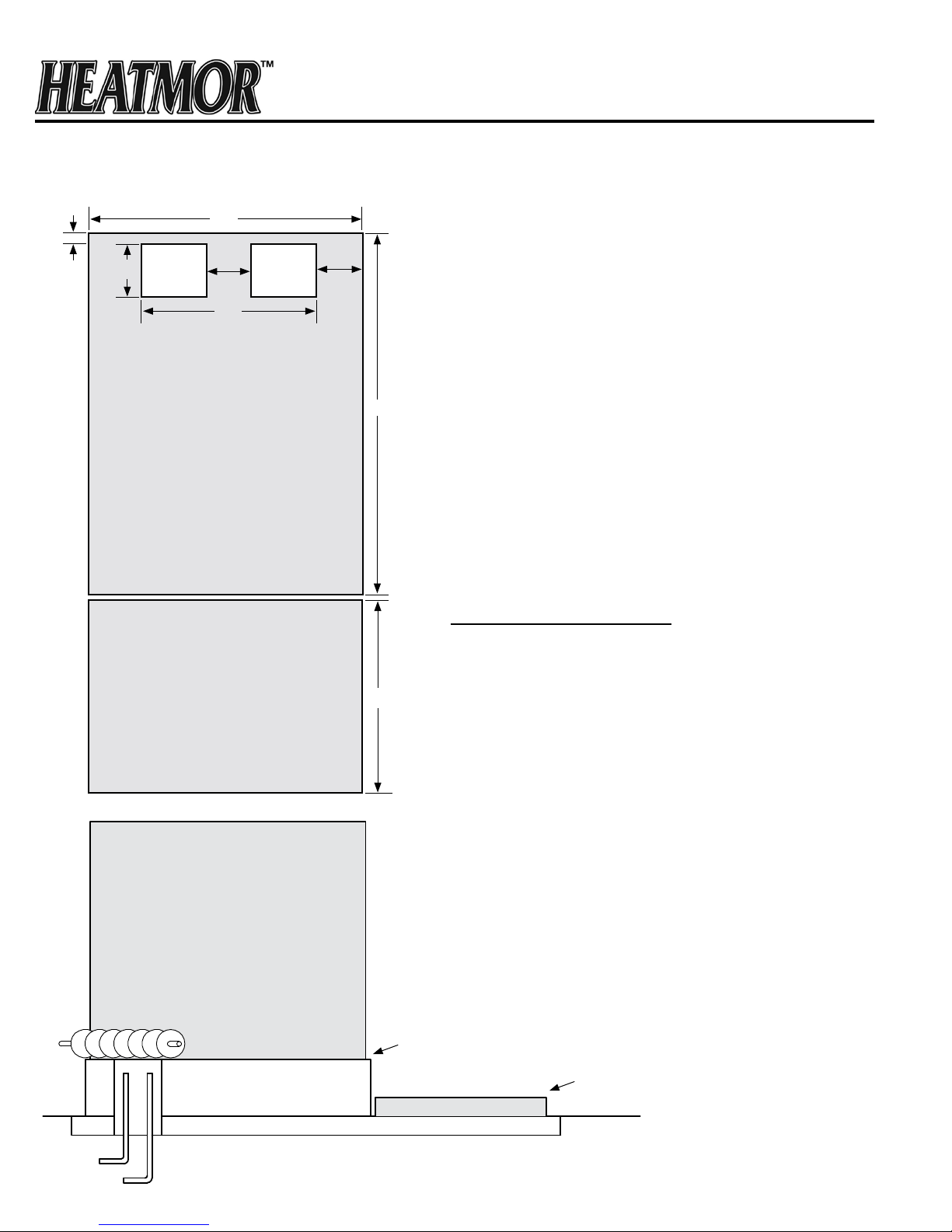
CHAPTER 7A
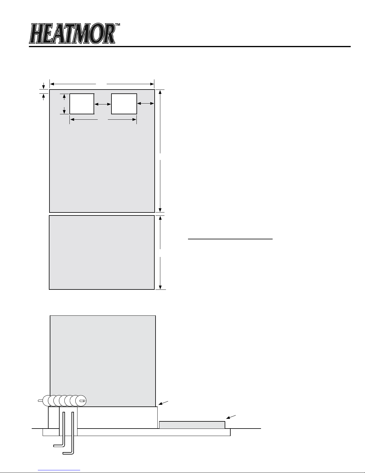
MODEL 100 PAD SPECIFICATIONS
50”
4”
10”
6”
AUGER
26”
HOLES FOR HOOK-UPS
12”
58”
The actual pad size is 50” x 58”. This gives
approximately 2” extra on all sides of furnace.
CAUTION: Do not exceed this length measurement.
Width can be wider if desired.
The bottom of the loading door is 24” above ground
or base of furnace. If you desire to have the leading
door higher, you can do so by making the pad depth
thicker.
Example: 12” instead of 4” or any gure in between.
Patio stones or separate cement pad in front of the
loading door should NOT be attached to main base
of furnace.
BASE: OUTDOOR FURNACE SITS ON THIS PAD
PATIO STONES OR SEPARATE CEMENT SLAB
FOR CONVENIENT LOADING
OUTDOOR FURNACE SITS HERE
48”
LOADING
DOOR
It is recommended to use steel mesh or R-bar
in pad for strength.
Benefits to raising the pad:
1. Gives space below the ash auger to place a pail
for convenient ash removal.
2. Allows better visibility of the rebox.
3. Less bending when adding wood.
4. Keeps smoke above the operator.
5. Protects the base of the
SIDE VIEW
HEATMOR™
.
ASH AUGER
CEMENT BASE
FOUR INCH GRAVEL BASE
UNDERGROUND LINES
CEMENT BASE 4” - 12”
HIGHER THAN WHERE THE
OPERATOR STANDS.
LOADING AREA
PATIO STONES OR
SEPARATE CEMENT SLAB.
GROUND
LEVEL
14
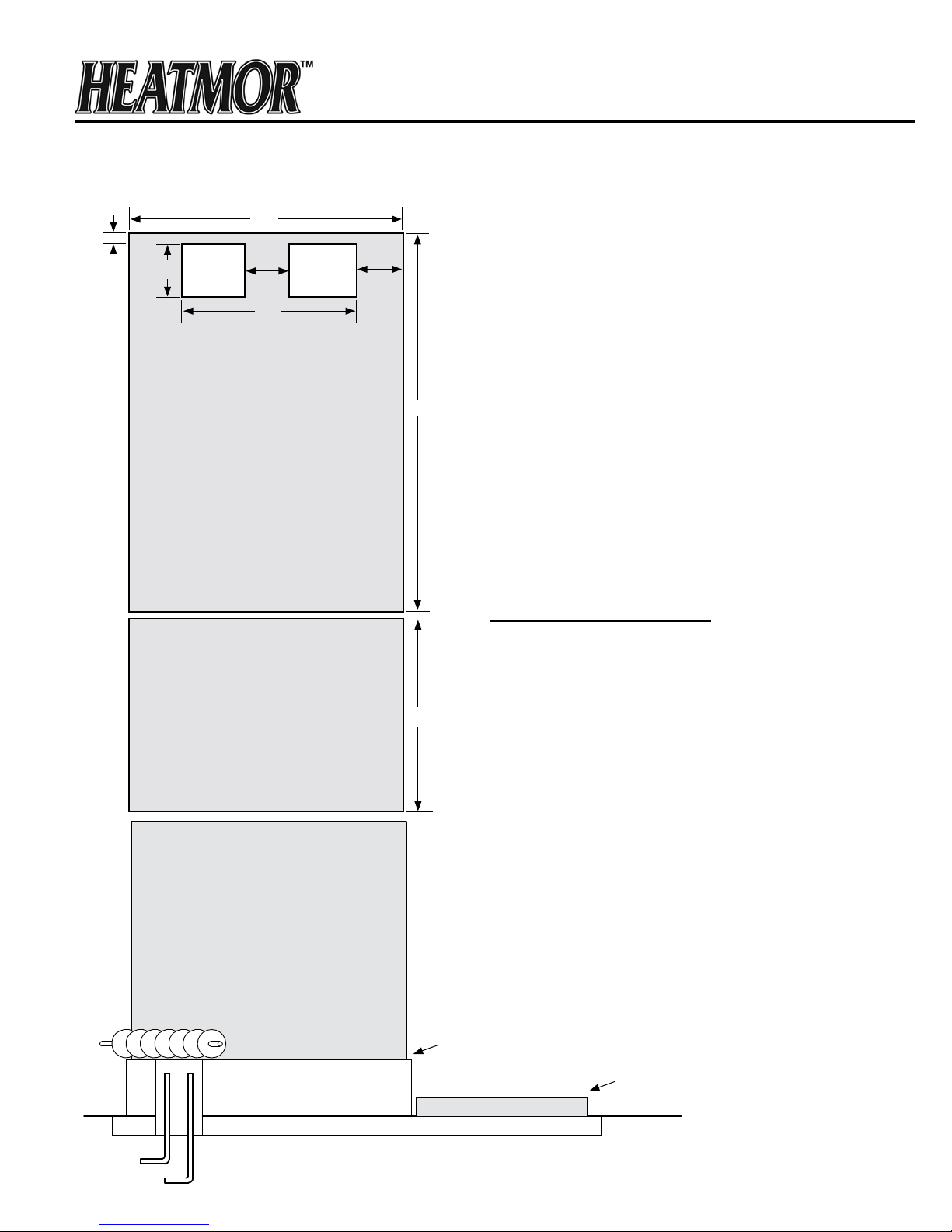
CHAPTER 7B
MODEL 200 PAD SPECIFICATIONS
50”
4”
10”
6”
AUGER
26”
HOLES FOR HOOK-UPS
12”
70”
The actual pad size is 50” x 70”. This gives
approximately 2” extra on all sides of furnace.
CAUTION: Do not exceed this length measurement.
Width can be wider if desired.
The bottom of the loading door is 24” above ground
or base of furnace. If you desire to have the leading
door higher, you can do so by making the pad depth
thicker.
Example: 12” instead of 4” or any gure in between.
BASE: OUTDOOR FURNACE SITS ON THIS PAD
PATIO STONES OR SEPARATE CEMENT SLAB
FOR CONVENIENT LOADING
48”
LOADING
DOOR
Patio stones or separate cement pad in front of the
loading door should NOT be attached to main base
of furnace.
It is recommended to use steel mesh or R-bar
in pad for strength.
Benefits to raising the pad:
1. Gives space below the ash auger to place a pail
for convenient ash removal.
2. Allows better visibility of the rebox.
3. Less bending when adding wood.
4. Keeps smoke above the operator.
5. Protects the base of the
HEATMOR™
.
OUTDOOR FURNACE SITS HERE
ASH AUGER
CEMENT BASE
FOUR INCH GRAVEL BASE
UNDERGROUND LINES
15
SIDE VIEW
CEMENT BASE 4” - 12”
HIGHER THAN WHERE THE
OPERATOR STANDS.
LOADING AREA
PATIO STONES OR
SEPARATE CEMENT SLAB.
GROUND
LEVEL
CHAPTER 7C
MODEL 400 PAD SPECIFICATIONS
50”
4”
10”
6”
AUGER
26”
HOLES FOR HOOK-UPS
BASE: OUTDOOR FURNACE SITS ON THIS PAD
12”
88”
The actual pad size is 50” x 88”. This gives
approximately 2” extra on all sides of furnace.
CAUTION: Do not exceed this length measurement.
Width can be wider if desired.
The bottom of the loading door is 24” above ground
or base of furnace. If you desire to have the leading
door higher, you can do so by making the pad depth
thicker.
Example: 12” instead of 4” or any gure in between.
Patio stones or separate cement pad in front of the
loading door should NOT be attached to main base
of furnace.
It is recommended to use steel mesh or R-bar
in pad for strength.
PATIO STONES OR SEPARATE CEMENT SLAB
FOR CONVENIENT LOADING
OUTDOOR FURNACE SITS HERE
ASH AUGER
CEMENT BASE
FOUR INCH GRAVEL BASE
Benefits to raising the pad:
1. Gives space below the ash auger to place a pail
for convenient ash removal.
2. Allows better visibility of the rebox.
48”
LOADING
DOOR
CEMENT BASE 4” - 12”
HIGHER THAN WHERE THE
OPERATOR STANDS.
3. Less bending when adding wood.
4. Keeps smoke above the operator.
5. Protects the base of the
SIDE VIEW
LOADING AREA
HEATMOR™
PATIO STONES OR
SEPARATE CEMENT SLAB.
GROUND
LEVEL
.
16
CHAPTER 8
INSTALLATION OF THE HEATMOR™ FURNACE
Installation should be performed by a qualied installer and will comply with all the requirements of
the authority having jurisdiction over the installation.
Principles
1) Need to have an airtight seal between the concrete base and the perimeter of the rebox base.
2) Need to seal the perimeter of the entire HEATMOR™ so rodents are not able to nd a home inside
the HEATMOR™.
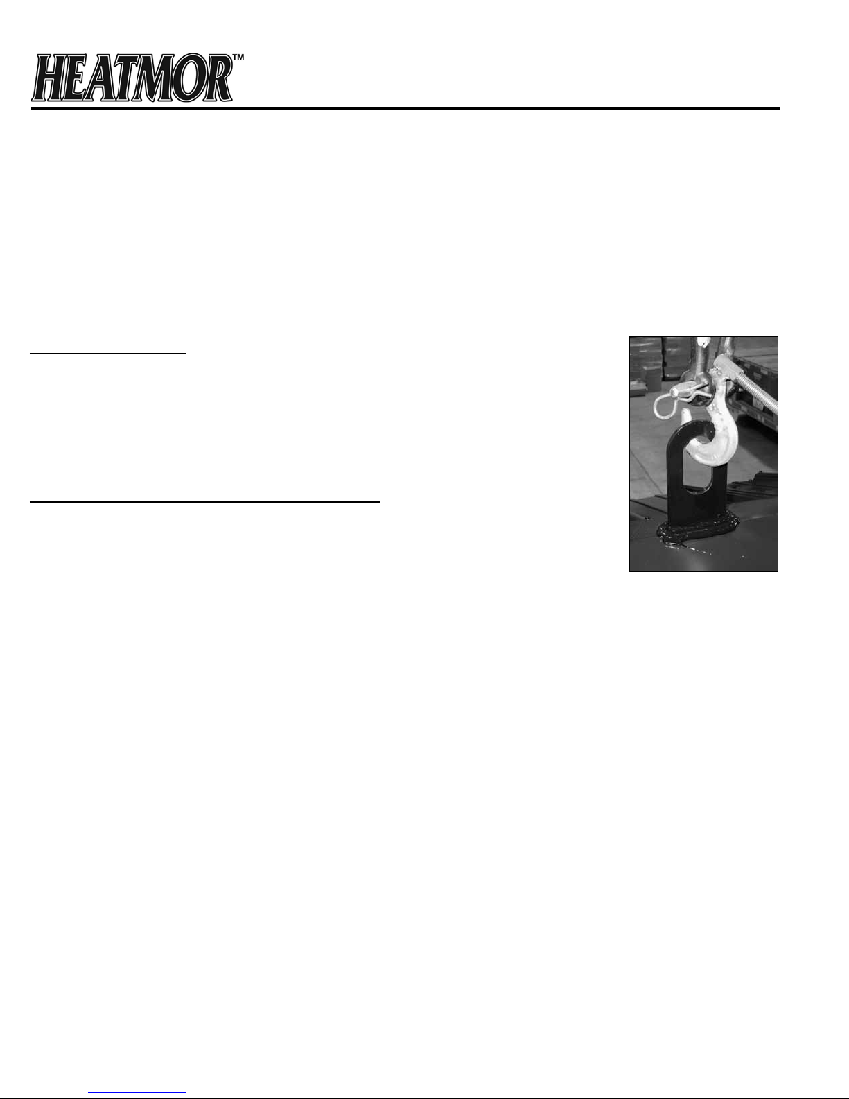
3) Need to lift the HEATMOR™ without damaging it.
Equipment Required
1) It is not possible to lift a HEATMOR™ with the forks of a forklift under the
HEATMOR™. It must be lifted from the top, by the lifting hook. A crane or
heavy backhoe works best, although a heavy duty farm tractor is acceptable.
a) With a farm tractor, extreme care must be taken to prevent the
HEATMOR™ from swinging and causing damage to the HEATMOR™.
Placing the HEATMOR™ on the Concrete Base
2) Before setting the HEATMOR™ onto the concrete base, it is a
good idea to place a solid sheet of the proper “reective air foil” (also called
bubble foil) between the concrete and the HEATMOR™. This will absorb ridges
in the concrete and make it easier to apply caulking around the inside
perimeter of the base of the HEATMOR™. This reective foil will also reect escaping heat
up into the sand, and help prevent air leaks into the rebox if cement cracks.
3) Make sure the total area of the base (where the sand is going) is on solid
concrete. Do not let the base extend past the hole in the concrete where the
lines come in.
4) After the HEATMOR™ is in place perform the following;
Lift Hook
Caulking around the Firebox Base
a) One person should get into the HEATMOR™.
b) Apply a substantial bead of caulking around the entire inside perimeter of the base. This
will give an airtight seal so no air will seep through the sand. This should require about three
tubes of High Temperature Silicone.
Caulking around the Outside Perimeter of HEATMOR™
c) With a sharp knife, trim any excess bubble foil
that extends past the base of the HEATMOR™.
d) Apply a bead of caulking around the entire outside
17
Filling the HEATMOR™ Outdoor Furnace Initially with Water
Before lling your HEATMOR™ furnace with water, all plumbing connections at the back of the HEATMOR™
furnace, all electrical hookups, and all heating appliances should be installed and tested for possible leaks.
HEATMOR™ suggests the use of brass ttings when installing the unit.
If you have any questions regarding installation of the furnace or any aspect of installation, contact your local
dealer.
Note: Never start a fire inside the firebox until the water jacket is full of water, and sand has been added to the
base to the correct level.
1) Close the bladder gate valve located at the front of the
HEATMOR™ furnace. This valve will ensure no water
can enter the bladder.
2) Close the bottom supply line valve at the back of the HEATMOR™.
3) Open the top return line valve at the back of the HEATMOR™.
4) Remove the weighted ball on the roof of the stove from the relief vent
pipe.
5) Connect the water source to the return line leading to the
HEATMOR™. Use a garden hose to add the water to the return line.
6) Turn on the source of water.
7) The pressured water will now ow through and remove the air out
of the return line as the water ows into the HEATMOR™.
8) Continue adding water until water ows out the relief vent pipe, onto the
roof of the HEATMOR™.
9) Turn off the source of water.
The HEATMOR™ is now full of water and the return line is also full of water and air free,
BUT the supply line leading from the HEATMOR™ to the building to be heated is still full of air.
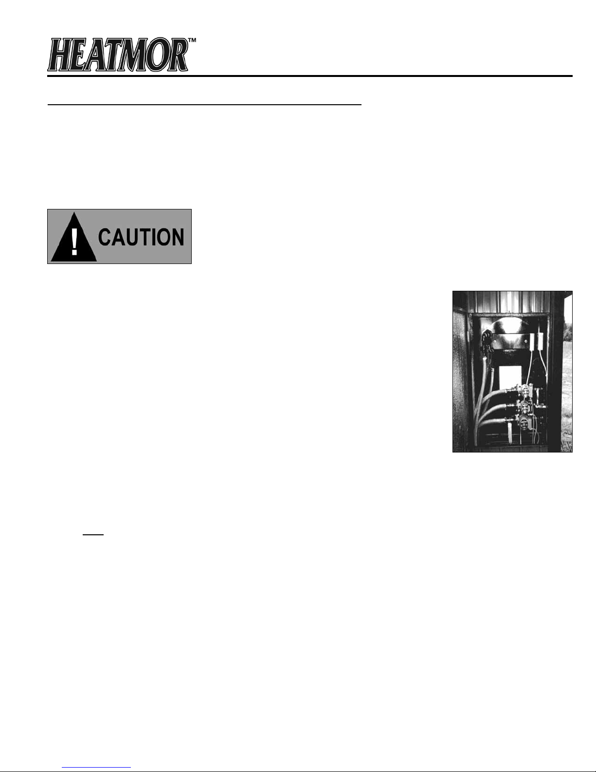
Rear of Furnace
10) Close the top return line valve at the back of the HEATMOR™.
11) Remove the garden hose that was used to deliver the source of water from the top return line,
BUT leave the garden hose valve open.
12) Open the bottom supply line at the back of the HEATMOR™ (bottom). The pressure of the water in
the HEATMOR™ will now force water from the HEATMOR™ through the supply line back into
the building to be heated. This water will soon discharge from where the garden hose
was connected. When there is a steady stream of water owing, the air will be removed from
that supply line. Usually it requires the removal of approximately ve gallons of water to ensure the line
is air-free.
NOTE: The circulator pumps cannot “push” much air through a system. They are designed to move
water not air.
13) Start the circulating pump. Remember to properly bleed air from the pump.
18
ABSOLUTELY NO FIRE IN THE FIREBOX WHEN PERFORMING THIS REPAIR. DO NOT
PERFORM THIS REPAIR WHEN UNIT WATER TEMPERATURE IS UNSAFE. ALWAYS WEAR PROPER
PERSONAL PROTECTIVE EQUIPMENT WHEN WORKING WITH WATER AND CHEMICALS.
Maintaining the Correct Amount of Water in the Bladder and in the HEATMOR™
1) Close the bladder gate valve located at the front of the HEATMOR™ furnace. Closing this valve will
ensure no water can enter the bladder.
2) Remove the weighted ball from the relief vent pipe.
3) Connect the water source to the return line leading to the HEATMOR™. Use a garden hose to add
the water to the return line.
4) Turn on the source of water, but only about half a full ow.
5) The pressured water will now ow through the return line as the water ows into the HEATMOR™.
6) Continue adding water until water ows out the relief vent pipe, onto the roof of the HEATMOR™.
Leave the water running. Some may continue to spill out onto the roof.
7) Place the weighted ball back onto the relief vent pipe.
8) Turn on the green bladder gate valve and let the bladder ll half full. You can check this by feeling the
bladder with your hand inserted through the bladder inspection cover plate.
9) Turn off the water when the bladder is half full.
Low Water Condition
If the water level is below the bladder port when the water heats up, air will enter the bladder instead of water.
To remove the air from the bladder, follow steps 1 through 7 above and make sure there is a good seal on the
weighted ball. Next:
1) Open the bladder gate valve.
2) CAREFULLY remove the bladder hose, allowing the bladder to empty its contents.
3) After bladder is empty of air/water, re-attach the bladder hose to the bladder gate valve and tighten
the hose clamp.
Next, follow steps 7-9 above.
NOTE: NEVER LIGHT A FIRE INSIDE THE FIREBOX UNTIL THE WATER JACKET IS FULL OF WATER,
AND SAND HAS BEEN ADDED TO THE BASE TO THE CORRECT LEVEL.
INSTALLATION SHOULD BE PERFORMED BY A QUALIFIED INSTALLER AND WILL COMPLY WITH ALL
THE REQUIREMENTS OF THE AUTHORITY HAVING JURISDICTION OVER THE INSTALLATION.
READ THROUGH THE ENTIRE OPERATIONS AND MAINTENANCE MANUAL BEFORE OPERATING
YOUR HEATMOR STAINLESS STEEL OUTDOOR FURNACE.
19
Initial Installation of Sand
Types of sand to use
1) Sand that does not contain clay, rocks or organic matter is appropriate. Use a sand that when
packed will not allow air to pass through. Mortar sand, or sand that is used in the redi-mix concrete
business is good. Never use gravel.
2) Model 100 CSS furnaces require approximately 0.18 cubic yards, Model 200 – 0.25 cubic yards, and
Model 400 – 0.38 cubic yards of sand.
Installation
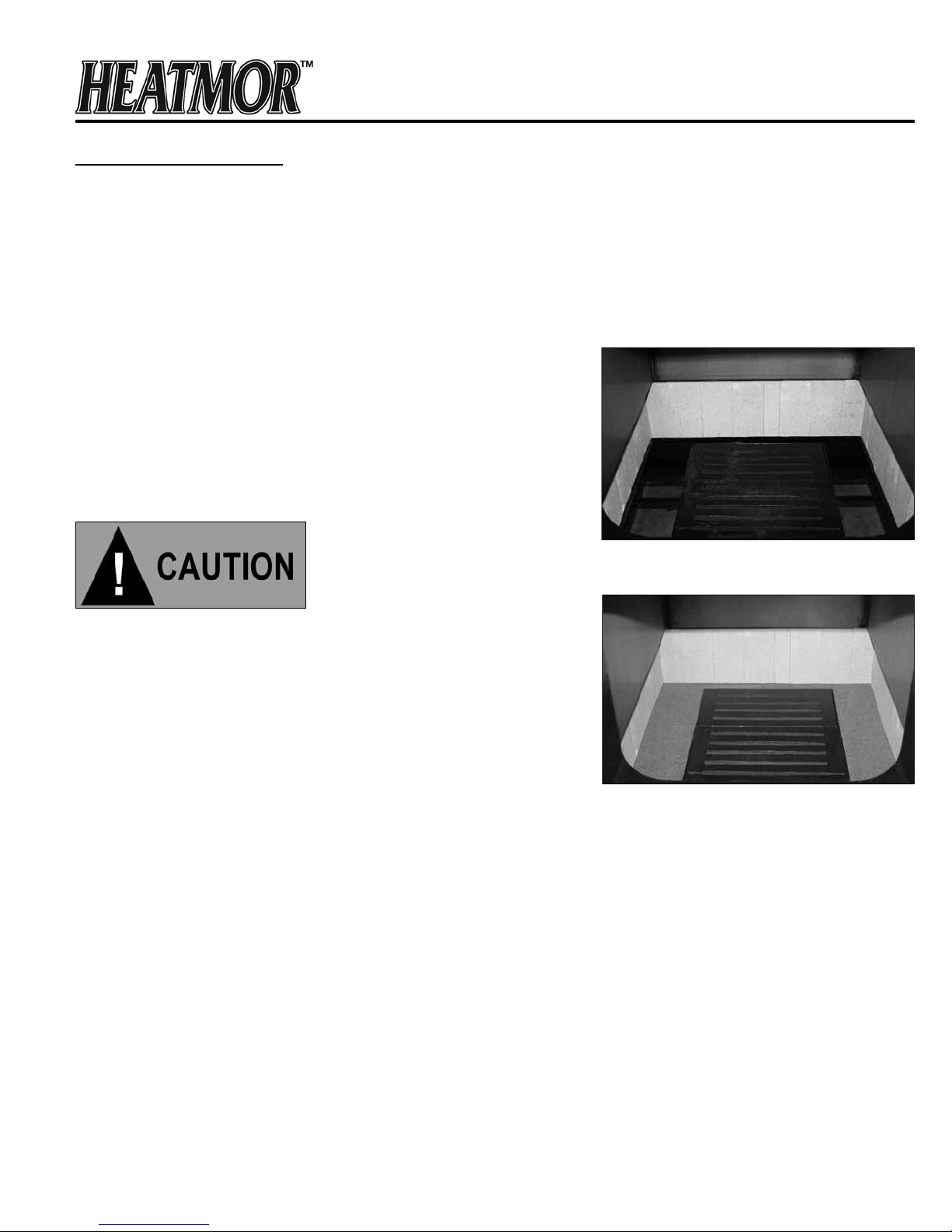
1) Cover the grates with a piece of cardboard.
2) One person enters the rebox.
3) Another person shovels the sand into the rebox while the
person inside packs the sand completely, using a piece of
wood like a 2 x 4 x 10 inches long.
4) Fill the base with sand, level to the top of the grates.
NOTE: NEVER LIGHT A FIRE INSIDE THE FIREBOX UNTIL
THE WATER JACKET IS FULL OF WATER AND SAND HAS
BEEN ADDED TO THE CORRECT LEVEL IN THE BASE.
Stove without Sand
Stove with Sand
20

CHAPTER 9
SAFE FURNACE OPERATION GUIDELINES
OPERATION
HEATMOR™ OUTDOOR FURNACES, MODEL 100 CSS, 200 CSS, AND 400 DCSS ARE CERTIFIED TO
BURN WOOD AND APPROVED COAL ONLY. CONTACT HEATMOR FOR APPROVED COAL TYPES.
Coal should only be burned in a HEATMOR™ Furnace equipped with a Shaker Grate System.
Burning of other materials may result in serious burns, health consequences, or damage to this furnace and
other components of the heating system and may void warranty.
***IMPORTANT NOTICE***
PLEASE REFER TO “FILLING YOUR HEATMOR™ FURNACE WITH WOOD,” FOR ADDITIONAL SAFE
LOADING PROCEDURES.
1) Never open the rebox door if the combustion air blower is operating or if you suspect a roaring
hot re inside the rebox.
2) Never open rebox door immediately after the combustion air blowers have shut off. If the water
temperature is very close to the high setting, you should assume the air combustion fans have
just shut off.
3) If there is more than a “wiff” of smoke coming from the chimney and the draft fan is off, do not
open the rebox door for at least two minutes. The burn cycle would have just ended and the rebox
will be full of unburned gases (smoke) that may ignite when fresh air is introduced.
4) Load the unit with wood carefully, but quickly. After loading wood make sure all debris is cleaned
from the rebox doorframe and gasket. Then close rebox door securely.
5) Keep the rebox door, ash auger tube cover cap, top ue cover plate, and the outer door of the
HEATMOR™ furnace closed at all times except for servicing and refueling.
6) Keep the locking handle on the outer door locked at all times when not servicing or refueling to
reduce the risk of tampering and possible injury.
7) Never add water to the HEATMOR™ furnace if the internal water temperature is over 212 degrees
Fahrenheit. Failure to adhere to this warning may cause a steam ash and result in an explosion.
21

8) Do not store combustible liquids or materials near the outdoor furnace. Adhere to the “Clearance to
Combustibles” guidelines.
9) Never use gasoline, kerosene, charcoal, lighter uid or similar liquids to start, re-start or
freshen up a re. Using such liquids may result in severe burns and injury.
10) When adding water, water treatment or maintaining the HEATMOR™ furnace, protective clothing
must be worn at all times.
11) Never leave the HEATMOR™ furnace unattended while the rebox door is open or unlatched.
12) Stay clear of any smoke emitting from the rebox.
13) Do not burn garbage, tires, solvents, engine oil, gasoline, or other inappropriate materials.
14) Store ashes outside, in a metal container with a metal tight tting lid, away from the outdoor
furnace and other buildings. No other waste should be placed in this container.
15) Wear a particle mask when removing ashes.
16) Ash auger may be hot after removing ashes.
17) In case of power failure, do not open any doors on the HEATMOR™. Monitor the water temperature
very closely. Refer to “freeze protection” in this manual.
18) In below freezing weather, if the water temperature in the HEATMOR™ drops below 40 degrees
Fahrenheit, drain all water from the HEATMOR™ immediately (if there is no anti-freeze in your system).
19) Water additives supplied with a HEATMOR™ do not give any freeze protection.
20) Always remove the weighted pop off ball before removing more than 5 gallons of water from the
HEATMOR™.
21) Check daily for creosote buildup until experience shows how often cleaning is necessary.
22) Be aware that the hotter the re, the less creosote is deposited, and that weekly cleanings can be
necessary in mild weather, even though monthly cleanings can be enough in the coldest months.
22

Lighting the HEATMOR™ for the First Time
When lighting the HEATMOR™ furnace for the rst time, all installations must be complete and the furnace
must be full of water. It is recommended to open bladder valve, reinstall the pop-off ball, and then build re to
bring the water up to temperature.
The lighting process is fairly simple. Please use the following steps simply as a guideline or contact your local
dealer for further instruction. Read the entire manual before lighting, so you have a complete working
knowledge of the furnace. Ask for a demonstration from your local dealer. It is very important to fully
educate all persons who will be lighting and fueling the HEATMOR™ furnace.
PLEASE READ THROUGH ALL “LIGHTING YOUR HEATMOR™” STEPS BEFORE LIGHTING
YOUR FURNACE.
1) Remove the weighted pop off ball from the relief vent pipe, on top of the HEATMOR™ furnace.
2) Close the green valve, supplying the bladder, located at the front of the stove.
3) Ensure that the furnace is full of water by running ve gallons of water onto the roof of the
HEATMOR™.
4) Ensure that there is 115-volt electrical power supplying the HEATMOR™ furnace.
5) Place some small pieces of wood (ve pounds) with paper into the rebox.
6) Place a few larger pieces of wood (20 pounds) on top of the smaller pieces.
7) Light the re.
8) Leave the re box door partially open to allow the re to start burning. The rebox door should only
need to be open about two inches. At this point the smoke should go up the chimney and not out
the rebox door.
9) Once the re is burning rather briskly, close the re box door and turn off the light switch which in
turn will make the combustion air blower(s) operate.
10) Operate the blowers for approximately 10 minutes.
11) Turn off the blowers.
Wait a few seconds to allow the combustion to decrease.
12) Open the rebox door and add a substantial amount of wood to the rebox.
13) Turn on the blowers.
14) Securely close the rebox door and outer door.
NOTE: Before the furnace is red up, the furnace is lled with water. While the furnace is lling with water, the
bladder is shut off to prevent excess water into the bladder, preventing over ll. When the furnace is freshly
lled the water temperature is approximately 50 degrees Fahrenheit. When the furnace is full of water you will
notice water coming out onto the roof from the relief vent pipe. At this point the water should be turned off and
the bladder valve opened. After the furnace is red up, the water temperature will start to increase. While the
water temperature rises, the water will expand as it heats up, causing the excess water to go into the bladder.
It will go into the bladder because it is the place of least restriction. This is another reason why we do not ll
the bladder initially, too much water in the bladder at cooler temperatures could cause the bladder to overll at
higher temperatures caused by the expansion of the water during temperature rise.
23

DEW POINT
NOTE: As the temperature inside of the rebox is increasing, there will be some sweating inside the rebox.
There may be streams of water running down the inside rebox walls and down the inside of the rebox door.
Water may run out onto the fan cover, below the rebox door, and even out the auger tube. THE HEATMOR™
IS NOT LEAKING!
Just as moisture collects on the inside of a warm house window on a cold outside day, the same thing is
occurring inside the HEATMOR rebox. The warm moisture in the smoke is condensing on the cold rebox
walls of the HEATMOR. In most typical situations, once the water temperature is above approximately 130
degrees Fahrenheit, the sweating will stop because you are above the dew point.
24

Loading Wood into the HEATMOR™
Please read through the entire HEATMOR™ Operation and Maintenance Manual and talk to your local dealer
for instruction. Ask for a demonstration from your local dealer. It is very important to fully educate all
those who will be loading the furnace with wood.
Loading a large amount of wood into the HEATMOR™ furnace once a day is not always best. We have found
that you have a more efcient re and produce less smoke when you add fuel twice a day. Example: Half of
the days’ demand in the morning and half in the evening. The number of loadings and the amount of wood
needed will vary depending on the amount of heat being removed.
Here are some suggested points to assist you in loading your furnace.
1) Make sure you have your fuel readily available to ll your furnace. (ie. a wheelbarrow full of wood
near the furnace)
2) Maintain a clear, clean area in front of the furnace.
3) Open the outer front door. This allows you access to the inner rebox door as well as opens the anti-
rollout device. This allows air into the rebox to decrease the possibility of the exhaust igniting
and creating a “ash back” before you open the main rebox door.
4) Turn on the light switch. The light should turn on and the combustion air blowers should turn off if
they were operating correctly.
5) Standing to the right, next to the exterior door, with your left hand and your left arm outstretched,
move the re box door handle out of the safety latch.
6) Crack the rebox door open about two inches and allow any pressure left over in the rebox to
escape.
7) Open the rebox door as you step backwards towards the exterior door. This allows you to be out of
the way if there is a “ash back” or exhaust exiting the door opening.
8) Set the rebox door handle into the holder provided on the outer door.
9) After all exhaust has been eliminated, give the ashes over the grates a light stirring with a long rake.
10) Add the necessary fuel to the rebox, being careful not to push ashes into the air boxes.
11) Close the rebox door and latch securely.
12) Turn off the light switch. This will return power to the blowers and turn off the light.
13) Close and lock the exterior door.
25
 Loading...