

Page 1
®
Heat Link
Plumbing, Heating, & Panels
Product Catalog / Price List
E ective July 1, 2014
2014
Canada
Page 2
Page 3

®
Heat Link
About Us
HeatLink is a multi-system supplier of potable water and radiant
hydronic heating/cooling and snow melt systems. For over 20 years
we have created comfortable and e cient heating, cooling and
plumbing systems for residential and commercial construction.
HeatLink’s radiant heating systems create a comfortable and energy
e cient environment for living. Our snow melt systems create safer
public and private spaces that reduce liability for property owners,
reduce maintenance, and ensure accessibility. Our well engineered
plumbing systems provide peace of mind for property owners
through extensive warranty protection, and enable quick and
e cient installations for builders and contractors.
History
HeatLink began as a family owned business developed to service
a number of industries including HVAC. The company grew to
meet the needs of builders, contractors, and architects and began
designing and installing radiant heating systems in 1985. Since
1985 HeatLink has grown into an industry leading designer and
manufacturer of radiant heating, cooling, and potable water systems.
HeatLink has developed and manufactured a long list of industry
rsts such as the “TwistSeal” tool-less manifold in 1996. The company
began manufacturing PEX-a tubing in 1998 and now supplies the
highest quality PEX-a systems to customers throughout North
America and parts of Europe and Asia.
HeatLink works with a network of experienced and successful partner
agencies to meet the design, system installation and training needs
of the construction industry, designers, and architects.
Solutions
HeatLink in an industry leader in providing a broad range of potable
water and radiant heating/cooling and snow melt systems for
customers throughout the world. Our focus from our inception
remains on creating well engineered and energy e cient solutions
that are easy to install and last a lifetime.
Company Description
Our innovative plumbing and heating systems help provide a
comfortable and worry free environment for people in residential
and commercial work and living spaces. We continue to design quiet
and energy e cient heating and potable water systems that are easy
to install and last a lifetime. HeatLink was built on a strong family
work ethic and a value system that remain the foundation for our
continuing growth and industry leadership role.
Page 4

Heat Link
www.heatlink.com
®
Table of Contents
Canada - July 1, 2014
Discounts Structure & Shipping Allowances ........................................ 3
Terms and Conditions of Sale, Delivery and Payment....................... 4
Heating
PEX Heating Tubing with O2 Barrier ......................................................... 5
PEX Heating Tubing Non Barrier ...............................................................7
TwistSeal® (55 mm) Manifold Assembly Kits......................................... 9
TwistSeal® (55 mm) Manifold Modules .................................................10
TwistSeal® Mini (40 mm) Manifold Assembly Kit...............................12
TwistSeal® Mini (40 mm) Manifold Modules .......................................13
TwistSeal® Manifold Accessories .............................................................14
1-1⁄4” Stainless Steel Manifolds ..................................................................16
1-1⁄4” Stainless Steel Manifold Accessories ............................................17
2” Stainless Steel Manifolds .......................................................................19
2” Stainless Steel Manifold Accessories ................................................20
Manifold Housings ....................................................................................... 22
PEX Compression Adapters ......................................................................23
2-way Injection Mixing ...............................................................................25
3-way Compact Mixing System ...............................................................26
3-way Mixing System ..................................................................................27
4-way Mixing System ..................................................................................28
Mixing Valves .................................................................................................29
Valves ................................................................................................................32
Mixing Valve Motors ....................................................................................35
Thermostatic Heads .....................................................................................36
Actuators .........................................................................................................37
Thermostats ....................................................................................................40
24V AC Relay ................................................................................................... 42
StatLink® Modules ........................................................................................43
Controls ............................................................................................................44
Sensors .............................................................................................................45
“Wet” System ..................................................................................................48
DryAbove™ System ...................................................................................... 51
DryBelow™ System .......................................................................................52
Floor Heating Accessories .........................................................................53
Chemicals ........................................................................................................56
Water Testing ..................................................................................................57
Sidestream Filter ........................................................................................... 58
Mechanical Room in a Box (Panels)
Introduction ...................................................................................................60
System Panel Selection ..............................................................................61
ECO - ECO Boiler Panels .............................................................................. 62
V100 - V100 Boiler Panels ...........................................................................64
CAD - CAD Boiler Panels .............................................................................66
ELBP - Electric Boiler Panels ......................................................................68
TMP – 3-Way Mixing Panels ...................................................................... 72
TWH – Tankless Water Heater Panels ..................................................... 80
HEP – Isolation Heat Exchanger Panels ................................................86
WHP - Water Heater Panels .......................................................................90
CDP – 2-Temperature Combi DHW Panels ..........................................92
SOL - Solar Heat Exchanger Panel ..........................................................98
SSM - Stainless Steel Manifold Panels ................................................ 100
SSP - Stainless Steel Manifold Pump Panels ..................................... 102
SSTS - Stainless Steel Manifold Small Mixing Panels ....................104
SSTL - Stainless Steel Manifold Large Mixing Panels .................... 106
SMP – Snow Melt Panels ......................................................................... 108
Snow Melt Panel Options & Accessories ........................................... 116
Plumbing
PureLink® Potable Water PEX-a Tubing .............................................. 117
PureLink® Pipe-in-Pipe ............................................................................. 121
EasyFit™ Manifold ...................................................................................... 122
HPP Multiport Tees .................................................................................... 125
SS Press Sleeves .......................................................................................... 126
PEX Insert Couplings ................................................................................ 128
PEX Insert Elbows ......................................................................................129
PEX Insert Threaded Elbows .................................................................. 130
PEX Insert FNPT Adapters ....................................................................... 131
PEX Insert Fixture Adapters ................................................................... 132
PEX Insert MNPT Adapters .....................................................................133
PEX Insert Sweat Adapters ..................................................................... 134
PEX Insert Tees ............................................................................................ 134
PEX Insert Plugs ......................................................................................... 137
Ball Valves ..................................................................................................... 138
Stubout Elbows .......................................................................................... 140
Accessories, Tools, and Parts
Accessories ................................................................................................... 141
Tools ............................................................................................................... 142
Parts ................................................................................................................ 150
Listing by Stk#
Listing by Stk# ............................................................................................. 160
2
Page 5

®
Heat Link
www.heatlink.com
Please note: this price list supersedes all previous price lists.
For your discount please contact your local sales representative.
Shipping Allowances
• Prices and speci cations are subject to change without notice.
• Products shipped in multiples of quantity listed only.
Standard shipping times: 3 days from con rmed order (or less).
D/C pickups: 3 days from con rmed order (or less), scheduled with local HeatLink shipping department.
Minimum order value: $100.00 net
Rush orders: Same day shipment if order con rmed by 11AM.
Next day if order con rmed after 11AM.
Next day freight charges applicable.
Rush charges may apply.
Backorders: Shipped with subsequent order to stocking distributor (if no subsequent order is in place, product will be
shipped freight prepaid ground n/c).
Prepaid freight: $ 5,000 net minimum order. Subject to change without notice.
Fuel surcharge: May apply on prepaid orders. Rates are subject to change without notice.
Discounts Structure & Shipping Allowances
Canada - July 1, 2014
3
Page 6

Heat Link
www.heatlink.com
®
Terms and Conditions of Sale, Delivery and Payment
Canada - July 1, 2014
General Provisions
1. (a) This agreement, performances of contract and quotations are made exclusively
(b) The Purchaser hereby accepts the terms and conditions herein contained
(c) In the event that any one or more of the provisions herein contained shall
Plans and Specifi cations
2. Drawings, specifi cations and technical data appended to or forming part of the
Prices and Quotations
3. (a) HeatLink Group Inc. hereby specifi cally reserves the right to change, alter,
(c) All contract prices are guaranteed for thirty (30) days from date of contract.
(d) Contracts for delivery of goods or performance of services without specifi c
Terms of Payment
4. (a) Save and except as otherwise specifi cally agreed upon in writing, all invoices
(b) Holdbacks or deductions of any kind whatsoever without prior written authori-
(c) Discounts, if any, shall be calculated on the cost of goods as per invoice,
(d) Payment will be in a form agreed to and acceptable by HeatLink Group Inc.
(e) Payments received shall be applied fi rstly to designated accounts, dishonour
(f) In the event the Purchaser defaults in payment or causes a cheque, bank
(g) Overdue accounts shall bear interest at the rate stated on the face of the
Reservation of Title and Property
5. (a) It is hereby expressly agreed that all goods shall remain the exclusive property
(b) Goods delivered shall not, in any event, become part of real estate and the
upon the terms and conditions set out below. Alterations or deviations from
the provisions herein contained shall not be binding upon HeatLink Group
Inc. unless confi rmed in writing.
in their entirety. Stipulations of terms and conditions contrary to the provision hereof according to the Purchaser’s business or purchasing practices,
invoicing, manner of payment or custom of the trade are hereby specifi cally
agreed to be inapplicable to this agreement.
become or be deemed to be invalid, illegal or unenforceable by operation of
law, the validity, legality and enforceability of the remaining provisions or any
part thereof shall not in any manner be affected or impaired thereby. In place
and stead of any such invalid, illegal or unenforceable provisions of any part
thereof, the parties hereto shall be deemed to have agreed upon terms and
conditions, which, as far as permitted by law, express the intent and purpose
of the within terms and conditions.
agreement shall at all times remain the property of HeatLink Group Inc., with
all rights reserved and shall not be provided, submitted or disclosed to third
parties without the express written consent of HeatLink Group Inc. Changes,
alterations, deletions or additions thereto shall not be binding upon HeatLink
Group Inc. unless confi rmed in writing.
amend or revoke quotations but the same shall become binding and irrevocable only upon written acceptance by both HeatLink Group Inc. and the
Purchaser or upon delivery to and acceptance of goods by the Purchaser.
(b) Prices are, save and except as otherwise agreed upon, as at HeatLink Group
Inc.’s location in Calgary, Alberta, Canada, exclusive of cost of packaging,
crating, freight or shipping, federal, provincial or local rates, tariffs and taxes
in effect on date of delivery.
Cost increases 30 days after contract date, including but not limited to cost
increases of materials, wages, fuel, transportation or energy charges and
increases in applicable federal, provincial and local rates, tariffs or taxes shall
be added to the contract price and form part thereof as if originally agreed
upon.
agreement as to price shall be subject to the price or prices in effect on the
date of delivery of goods.
or accounts, as the case may be, shall become due and payable in full without
deduction whatsoever thirty (30) days after invoice or account date.
zation from HeatLink Group Inc. are expressly prohibited.
exclusive of cost of packaging, crating, freight or shipping, federal, provincial
or local rates, tariffs or taxes, where applicable, or other costs or surcharges
beyond control of HeatLink Group Inc.
All costs for dishonour, presentment for payment or collection shall be at
the expense of the Purchaser and Payor. All payments by cheque, whether
certifi ed or uncertifi ed, shall be deemed as having been received on the date
of acceptance for payment of the said cheque or cheques by the Purchaser’s
or Payor’s bank, trust company or fi nancial institution upon whose account
the cheque has been issued.
or collection; secondly, to outstanding interest charges on the oldest accounts;
and, thirdly, the balance, if any, of any payment shall be applied to the most
recent accounts, outstanding balance or balances. If an account is past due
at the time of payment, then application of received funds will be in the order
best interest to HeatLink Group Inc.
draft or money order to be dishonoured or stops payment thereon, or HeatLink
Group Inc. shall deem the Purchaser insecure, all accounts shall forthwith
become due and payable notwithstanding any agreement as to credit or
periodic payment.
invoice or (if no rate is displayed on the invoice), 2% calculated and compounded monthly.
of HeatLink Group Inc. and title shall not pass until payment in full of all invoices
or accounts rendered, including cost of goods, packaging, carting, shipping or
freight charges, federal, provincial or local taxes, rates and tariffs, insurance,
extras to contract, interest charges, exchange or collection expenses and
other sums or charges applicable has been received pursuant to the terms
and conditions herein contained.
Purchaser shall at all times take or initiate all steps necessary to preserve
HeatLink Group Inc.’s right, title and property to such goods.
(c) The Purchaser shall not permit any goods sold or delivered by HeatLink
(d) In the event of breach of contract by the Purchaser of the terms or condi-
(e) Seizure of goods by HeatLink Group Inc. shall not be deemed to constitute
Delivery of Goods
6. (a) HeatLink Group Inc. shall at all times use its best efforts to maintain the
(b) Delivery dates or periods shall be extended by reason of delays causes by
(c) In the event of delay in delivery of goods caused by the Purchaser for any
Risk of Property
7. (a) Commencing on the date of delivery of goods for shipment or transport to
(b) Any goods or part thereof delivered for shipment or transport to the Purchaser
(c) Defi ciencies or defects in goods or part thereof shipped or the shipment of
Return of Goods
8. (a) All or any goods returned without prior authorization by HeatLink Group Inc.
(b) If returns are authorized by HeatLink Group Inc., goods will be accepted as
(i) New and unused goods upon authorization by HeatLink Group Inc.,
(ii) Outdated goods, with freight prepaid plus 25% restocking charge plus
Insurance
9. During the period commencing with the delivery of goods for shipment or
Applicable Law
10. All disputes, claims or demands arising from or relating to warranties, guar-
Group Inc. to be pledged or encumbered without express written consent from
HeatLink Group Inc. In the event of seizure by third parties, the Purchaser
shall forthwith disclose HeatLink Group Inc.’s reservation of title, right and
property to such goods and shall forthwith notify HeatLink Group Inc. of such
seizure and shall assist HeatLink Group Inc. at the Purchaser’s cost in the
preservation and enforcement of HeatLink Group Inc.’s right, title and property
to the said goods.
tions herein contained and, in particular, default of payment of invoices as
hereinbefore provided, HeatLink Group Inc. shall be entitled, without prior
notice, to demand delivery up of goods sold and delivered and to seize the
same wherever the same may be located at any time of day or night or to
cause its agents, workmen or bailiffs to seize the same, wherever the same
may be located at any time of day or night notwithstanding the goods may
be in possession of a subsequent purchaser or user.
termination of contract or contractual rights and obligations as between
HeatLink Group Inc. and the Purchaser.
delivery dates agreed upon. The delivery date or period shall be deemed
to have been maintained or complied with in all events, cases or situations
where the goods to be delivered leave HeatLink Group Inc.’s premises on or
before such date, before the expiry of such period or the Purchaser is notifi ed
before the applicable date that the goods are ready for shipment.
labour shortages, strikes or lockouts or other circumstances beyond the reasonable control of HeatLink Group Inc. Any delay or postponement of delivery
to HeatLink Group Inc. of goods and supplies by its suppliers, subcontractors
or co-contractors caused by strike, lockout, labour shortage or unrest or other
causes beyond the reasonable control of HeatLink Group Inc., its suppliers,
subcontractors or co-contractors shall in like manner extend delivery dates
and periods as if the same applied to HeatLink Group Inc.
reason whatsoever, HeatLink Group Inc. shall be entitled to charge the cost
of storage calculated at the rate of one half (1/2%) percent per month upon
the cost of goods, such calculation commencing one month after delivery of
Notice of Readiness for shipment and continuing for each and every month
or part thereof thereafter until the goods can be delivered to the Purchaser.
the Purchaser, the said goods or any part thereof shall be at the risk of the
Purchaser.
from the factory Calgary, Alberta, or elsewhere, including goods with unessential or minor defects, shall be deemed to have been accepted by the
Purchaser without recourse.
the wrong goods, or part or part thereof, shall be endorsed upon the bill of
lading and shall be communicated to HeatLink Group Inc. in writing within
three (3) business days of arrival at destination. Failing such notifi cation, the
Purchaser shall be deemed to have accepted the goods without recourse.
shall not be accepted.
follows:
with freight to be prepaid plus 25% restocking charge.
(c) In all cases, unless express written authorization is given, goods must be
refurbishing costs.
returned in condition for immediate resale. If goods and packaging are not
in condition for immediate resale, HeatLink Group Inc. reserves the right
to refuse to accept the returned goods, charge additionally for refurbishing
goods or packaging, or any other agreed to return remedy negotiated with
the customer. In all cases, HeatLink Group Inc. will have the fi nal approval
as to whether returned goods are accepted or unaccepted under any of the
above remedies.
transport to the Purchaser and ending upon receipt of payment in full for
the said goods pursuant to the terms and conditions hereof, the Purchaser
shall insure the said goods in the joint names of HeatLink Group Inc. and the
Purchaser against all risk of loss or damage howsoever caused.
antees, representations authorized and published by HeatLink Group Inc.,
and from the terms and conditions herein contained and all claims, demands,
rights or liabilities arising from such warranties, guarantees, representations
or terms and conditions shall be determined in accordance with the laws of
the Province of Alberta, Canada.
4
Page 7
Heat Link
3
1
1
1
1
5
5
5
3
3
3
3
1
1
1
1
www.heatlink.com
®
PEX Heating Tubing with O
Barrier
2
Canada - July 1, 2014
Special
Order*
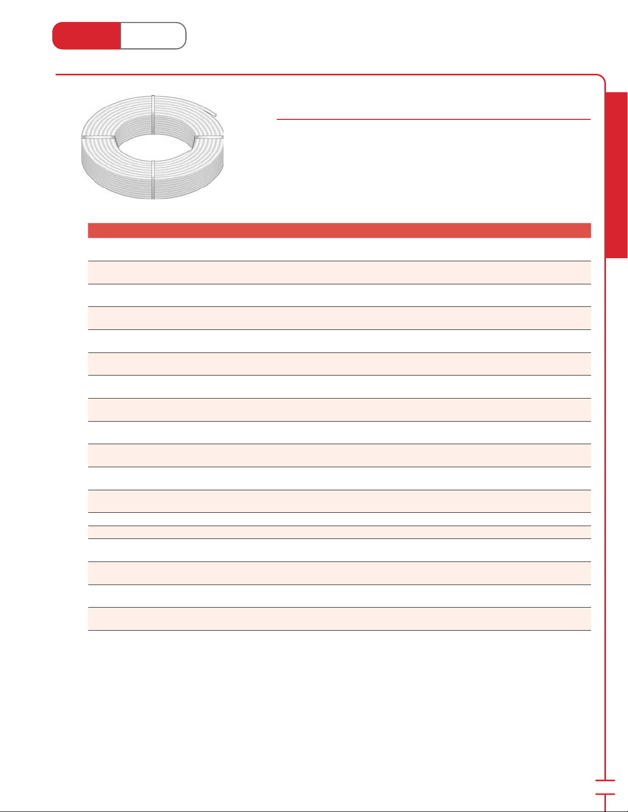
PEX Tubing Coils with O2 Barrier
94000 Series
High molecular cross-linked poly eth yl ene (PEX) with minimum bend ing radii of
6× the diameter at 68°F (20°C). Maximum op er at ing tem per a ture: 180°F @ 100 PSI
(82°C @ 690 kPa). Covered by a twen ty- ve year manufacturer’s limited warranty.
Comes with oxygen di u sion barrier which pre vents ox y gen from entering the
heat ing system through the tubing wall.
Stk# Description Pkg Qty Carton Qty Unit List Price / Unit
Stk# Description Pkg Qty Skid Qty Unit List Price / Unit
94312
94205
94305
94505
94105
94319
94519
94119
94922
94322
94522
94122
94128 1" 100ft O
94528 1" 500ft O
94135
94335
94141
94341
⁄8" 300ft O2 Barrier HeatLink® UV Stabilized PEX-a
Tubing
⁄2" 250ft O2 Barrier HeatLink® UV Stabilized PEX-a
Tubing
⁄2" 300ft O2 Barrier HeatLink® UV Stabilized PEX-a
Tubing
⁄2" 500ft O2 Barrier HeatLink® UV Stabilized PEX-a
Tubing
⁄2" 1000ft O2 Barrier HeatLink® UV Stabilized PEX-a
Tubing
⁄8" 300ft O2 Barrier HeatLink® UV Stabilized PEX-a
Tubing
⁄8" 500ft O2 Barrier HeatLink® UV Stabilized PEX-a
Tubing
⁄8" 1000ft O2 Barrier HeatLink® UV Stabilized PEX-a
Tubing
⁄4" 100ft O2 Barrier HeatLink® UV Stabilized PEX-a
Tubing
⁄4" 300ft O2 Barrier HeatLink® UV Stabilized PEX-a
Tubing
⁄4" 500ft O2 Barrier HeatLink® UV Stabilized PEX-a
Tubing
⁄4" 1000ft O2 Barrier HeatLink® UV Stabilized PEX-a
Tubing
Barrier HeatLink® UV Stabilized PEX-a Tubing 1 19 coil
2
Barrier HeatLink® UV Stabilized PEX-a Tubing 1 5 coil
2
⁄4" 100ft O2 Barrier HeatLink® UV Stabilized PEX-a
1-
Tubing
1-
⁄4" 300ft O2 Barrier HeatLink® UV Stabilized PEX-a
Tubing
1-
⁄2" 100ft O2 Barrier HeatLink® UV Stabilized PEX-a
Tubing
1-
⁄2" 300ft O2 Barrier HeatLink® UV Stabilized PEX-a
Tubing
1 40 coil
1 40 coil
1 40 coil
1 20 coil
1 16 coil
1 20 coil
1 16 coil
1 12 coil
3 48 coil
1 16 coil
1 12 coil
1 5 coil
1 14 coil
1 5 coil
1 5 coil
1 5 coil
Radiant Heating & Cooling
* Check with your local representative for availability.
5
Page 8
Heat Link
1
1
15
16
3
1
1
1
3
www.heatlink.com
Stk# Description Pkg Qty Carton Qty Unit List Price / Unit
Stk# Description Pkg Qty Master Bag Unit List Price / Unit
Radiant Heating & Cooling
94222
94228
94235
94241
⁄4" 10×20ft O2 Barrier HeatLink® UV Stabilized PEX-a
1" 5×20ft O
1-
⁄4" 5×20ft O2 Barrier HeatLink® UV Stabilized PEX-a
1-
⁄2" 5×20ft O2 Barrier HeatLink® UV Stabilized PEX-a
®
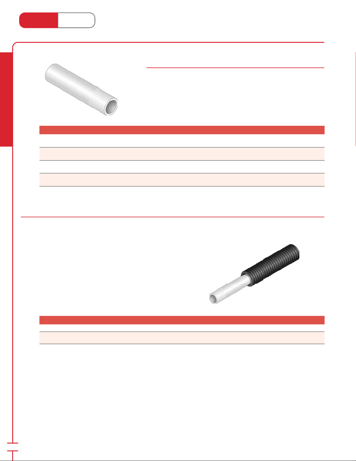
PEX Tubing Straight Lengths with O2 Barrier
94000 Series
High molecular cross-linked poly eth yl ene (PEX) with minimum bend ing radii of
6× the diameter at 68°F (20°C). Maximum op er at ing tem per a ture: 180°F @ 100 PSI
(82°C @ 690 kPa). Covered by a twen ty- ve year manufacturer’s limited warranty.
Comes with oxygen di u sion barrier which pre vents ox y gen from entering the
heat ing system through the tubing wall.
Tubing
Barrier HeatLink® UV Stabilized PEX-a
2
Tubing
Tubing
Tubing
PEX Heating Tubing with O
Canada - July 1, 2014
1 20 bundle
1 20 bundle
1 20 bundle
1 20 bundle
Barrier
2
HeatLink® O2 Barrier Pipe-in-Pipe
94000 Sheathed Series
PEX-a carrier tubing speci ed on previous pages. The exible, impact resistant red PE sheath designed as a raceway for electrical
installations provides mechanical and UV protection to the PEX-a carrier tubing. The sheath allows for easy replacement of the PEX-a carrier
tubing if needed.
Minimum bending radius @ 68˚F (20˚C) for:
PE sheath is rated to UL94HB “Tests for Flammability of Plastic Materials.”
Corrugated sheath outside diameter for:
Stk# Description Pkg Qty Carton Qty Unit List Price / Unit
Stk# Description Pkg Qty Skid Qty Unit List Price / Unit
New!
Special
Order*
94305rs
94322rs
⁄2" 300' O2 Barrier HeatLink® Pipe-in-Pipe Red Sheath 1 14 coil
⁄4" 300' O2 Barrier HeatLink® Pipe-in-Pipe Red Sheath 1 9 coil
⁄2" = 3" (77 mm)
15
⁄2" =
⁄
16" (23 mm)
6
* Lead time may vary. Call to con rm time line.
Page 9
Heat Link
3
1
1
1
3
3
3
www.heatlink.com
®
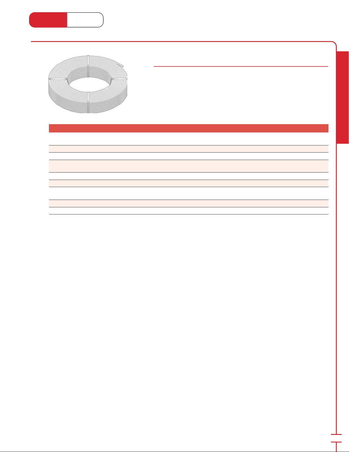
PEX Heating Tubing Non Barrier
Canada - July 1, 2014
WSL
Non Barrier PEX Tubing Coils
20000 & 99000 Series
High molecular cross-linked poly eth yl ene (PEX) with minimum bend ing radii of
6× the diameter at 68°F (20°C). Maximum operating tem per a ture: 180°F @ 100 PSI
(82°C @ 690 kPa). Covered by a twen ty- ve year manufacturer’s limited warranty.
Stk# Description Pkg Qty Carton Qty Unit List Price / Unit
Stk# Description Pkg Qty Skid Qty Unit List Price / Unit
99212
20305
20505
20905
20322
20522
20922
20128 1" 100ft Blue PureLink® Plus UV Stabilized PEX-a Tubing 1 19 coil
20328 1" 300ft Blue PureLink® Plus UV Stabilized PEX-a Tubing 1 9 coil
⁄8" 200ft Non-Barrier HeatLink® UV Stabilized PEX-a
⁄2" 300ft Blue PureLink® Plus UV Stabilized PEX-a Tubing 1 32 coil
⁄2" 500ft Blue PureLink® Plus UV Stabilized PEX-a Tubing 1 20 coil
⁄2" 1000ft Blue PureLink® Plus UV Stabilized PEX-a
⁄4" 300ft Blue PureLink® Plus UV Stabilized PEX-a Tubing 1 14 coil
⁄4" 500ft Blue PureLink® Plus UV Stabilized PEX-a Tubing 1 9 coil
⁄4" 1000ft Blue PureLink® Plus UV Stabilized PEX-a
Tubing
Tubing
Tubing
1 coil
1 14 coil
1 5 coil
Radiant Heating & Cooling
7
Page 10
®
3
1
5
3
3
1
Heat Link
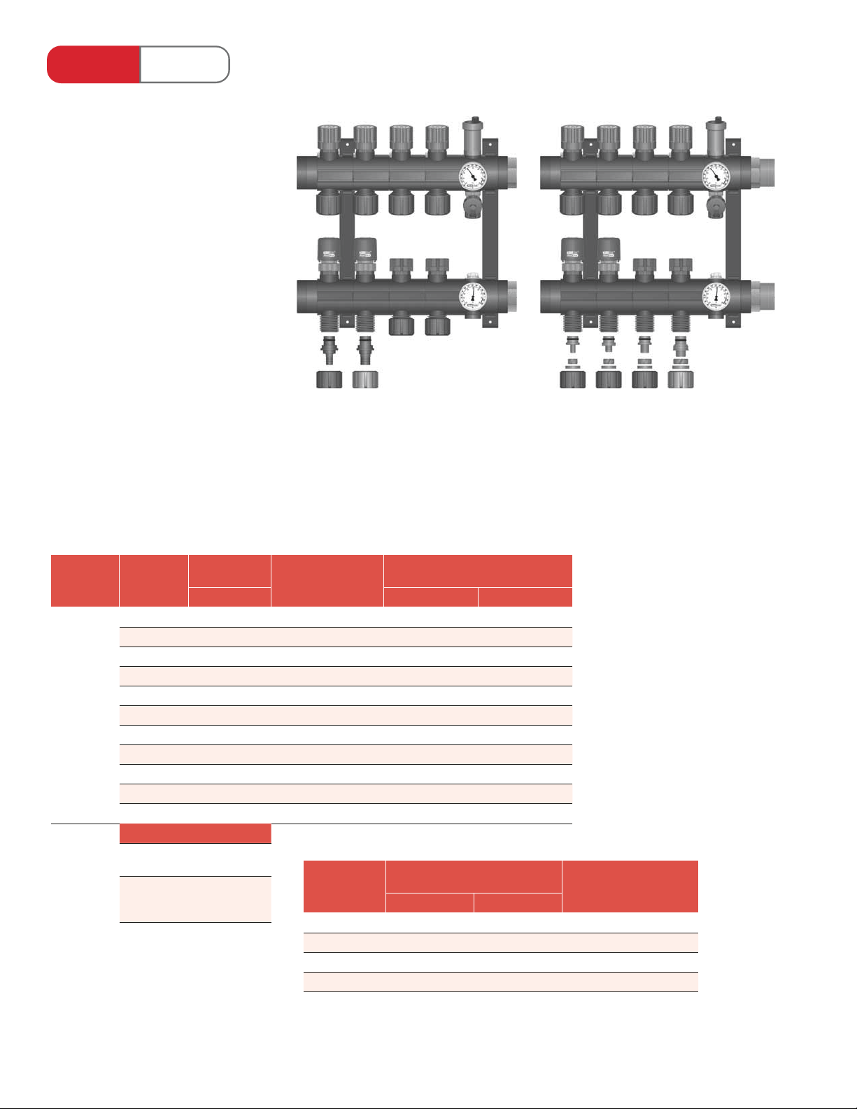
TwistSeal® (55 mm) Manifolds
Features & Bene ts :
• Modular “tool-less” assembly.
• Multiple con gurations from basic
to deluxe (all interchangeable; can
be recon gured on-site).
• Unlike a xed loop manifold,
loops can be added or removed as
required.
• Stock is exible, as there is no need
to stock xed-length manifolds.
Minimal SKUs on the shelf.
• Balancing return.
• Zone valve supply with manual
shut-o ; accepts optional actuators.
• Max. trunk ow rate:
79400 kit - 18 US gpm (4.1 m3/h)
79402 kit - 22 US gpm (5 m3/h)
• Max. circuit ow rate:
2.5 US gpm (0.57 m3/h)
• 3⁄8", 1⁄2", 5⁄8", and 3⁄4" tubing to manifold
connecters available.
• Test rated to over 230 PSI @ 180°F
water temperature.
• 5 year limited warranty.
L to R
⁄2" & 3⁄4" PEX insert
tubing to manifold
connecters
(79400 assembly kit shown with 4× 78400
module pairs and 2 actuators)
Typical Applications:
• Commercial.
• Snow melting.
L to R
⁄8", 1⁄2", 5⁄8", & 3⁄4"
tubing to manifold
connecters
(79402 assembly kit shown with 4× 78400
module pairs and 2 actuators)
Assembly
Kit
79400
or
79401
or
79402
Choose
# of Loops
2 2× 78400 - 71724 71424
3 3× 78400 - 71724 71424
4 4× 78400 - 71730 71430
5 5× 78400 - 71730 71430
6 6× 78400 1× 79991 71743 71430
7 7× 78400 1× 79991 71743 71442
8 8× 78400 1× 79991 71743 71442
9 9× 78400 2× 79991 71743 71442
10 10× 78400 2× 79991 71743 71442
11 11× 78400 2× 79991 n/a n/a
12 12× 78400 3× 79991 n/a n/a
Actuator Selection
Actuator
with LED
Actuator
with End
Switch
Module Type
Balancing Recessed** Surface Mount
56200
56230
Additional Brackets
Tubing Size
⁄8" 77012 n/a 2× 86005
⁄2" 77005 2× 23015 2× 86005
⁄8" 77019 n/a 2× 86020
⁄4" 77022 2× 23032 2× 86022
Recommended Housing*
Tubing to Manifold Connecters
/ Loop
Compression PEX Insert
Conduit Elbows / Loop
for “Wet” Installation
* Recommended housing based on 79402 kit and 90° mains piping.
** Thermometers must be removed.
Page 11
Heat Link
www.heatlink.com
®
TwistSeal® (55 mm) Manifold Assembly Kits
Canada - July 1, 2014
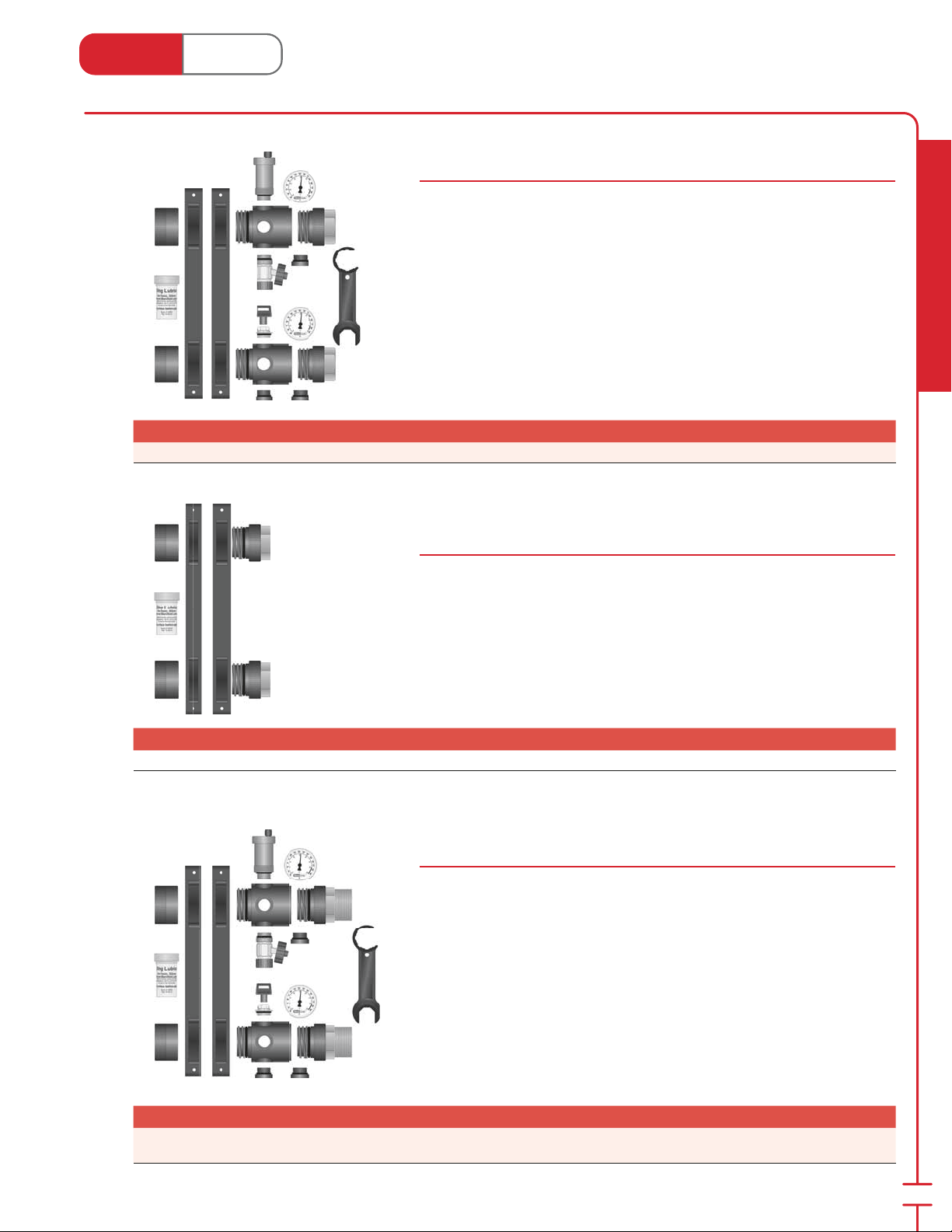
TwistSeal® (55 mm) Deluxe Manifold Assembly Kit
Stk# 79400
This package contains the items need ed to assemble a Deluxe TwistSeal®
Manifold. Contents include:
• 2 mounting brackets
• 2 - 1" FNPT supply end connections
• 2 closed end caps
• 1 lube bottle
• 2 cross tees c/w 3 - 1⁄2" cross tee plugs
• 1 thermometer pair c/w wells
• 1 manual air vent with 1 key
• 1 au to mat ic air vent
• 1 hose bib
• 1 wrench for plastic nut
Stk# Description Pkg Qty Carton Qty Unit List Price / Unit
79400 1" TwistSeal® (55mm) Deluxe Manifold Assembly Kit 1 20 ea.
TwistSeal® (55 mm) Basic Manifold Assembly Kit
Stk# 79401
This package contains the items need ed to assemble a TwistSeal® Man i fold.
Contents include:
• 2 mounting brackets
• 2 - 1" FNPT supply end connections
• 2 closed end caps
• 1 lube bottle
Wrench (#79922) sold separately.
Radiant Heating & Cooling
Stk# Description Pkg Qty Carton Qty Unit List Price / Unit
79401 1" TwistSeal® (55mm) Basic Manifold Assembly Kit 1 20 ea.
TwistSeal® (55 mm) Commercial Manifold Assembly Kit
Stk# 79402
This package contains the items need ed to assemble a Com mer cial TwistSeal®
Manifold. Contents include:
• 2 mounting brackets
• 2 - 1-1⁄2" MNPT supply end connections
• 2 closed end caps
• 1 lube bottle
• 2 cross tees c/w 3 - 1⁄2" cross tee plugs
• 1 thermometer pair c/w wells
• 1 manual air vent with 1 key
• 1 au to mat ic air vent
• 1 hose bib
• 1 wrench for plastic nut
Stk# Description Pkg Qty Carton Qty Unit List Price / Unit
79402
1-1⁄2" TwistSeal® (55mm) Commercial Manifold Assembly
Kit
1 20 ea.
9
Page 12
Heat Link
www.heatlink.com
Stk# Description Pkg Qty Carton Qty Unit List Price / Unit
79991 TwistSeal® (55mm) Mounting Bracket 1 ea.
Radiant Heating & Cooling
®
TwistSeal® (55 mm) Manifold Modules
Canada - July 1, 2014
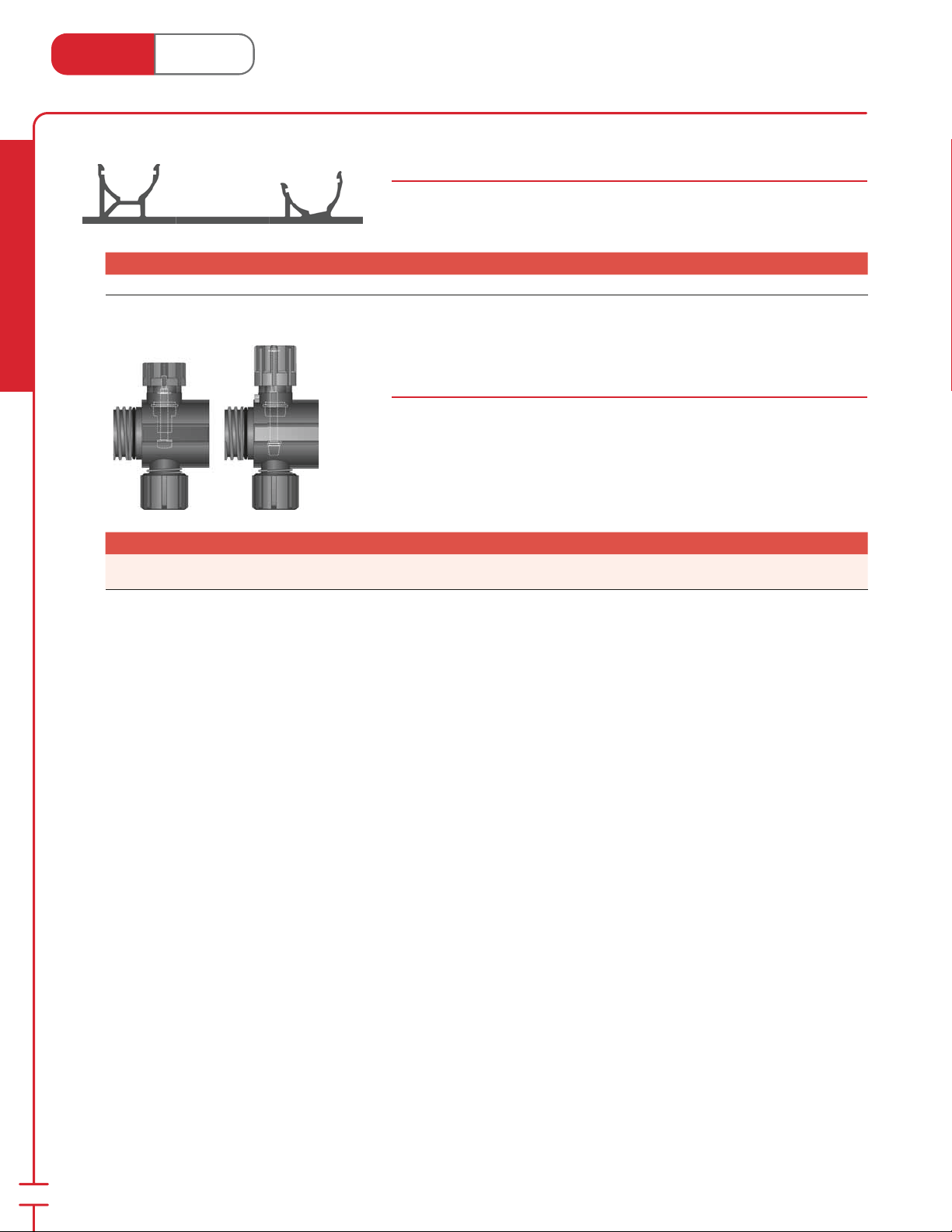
Mounting Bracket (55 mm)
Stk# 79991
Plastic mounting bracket which al lows easy ‘snap-on’ mount ing of manifolds.
TwistSeal® Deluxe (55 mm) Supply / Return Modules c/w Heavy
Duty Zone Valve Supply & Balancing Return
Stk# 78400
The supply module provides on/o manual control to allow iso la tion of individual
loops, and may be tted for electric actuator and ther mo stat op er a tion. The
return mod ule permits the bal anc ing of the ow rate. Comes with o-rings.
Modules can be locked in place with a couple of turns. No threaded rod, solder, or
tools required. Just twist and seal.
Stk# Description Pkg Qty Carton Qty Unit List Price / Unit
78400
TwistSeal® Deluxe (55mm) Z.V. Supply & Balancing
Return Module Pair
1 10 pair
10
Page 13
®
3
1
3
1
5
3
Heat Link
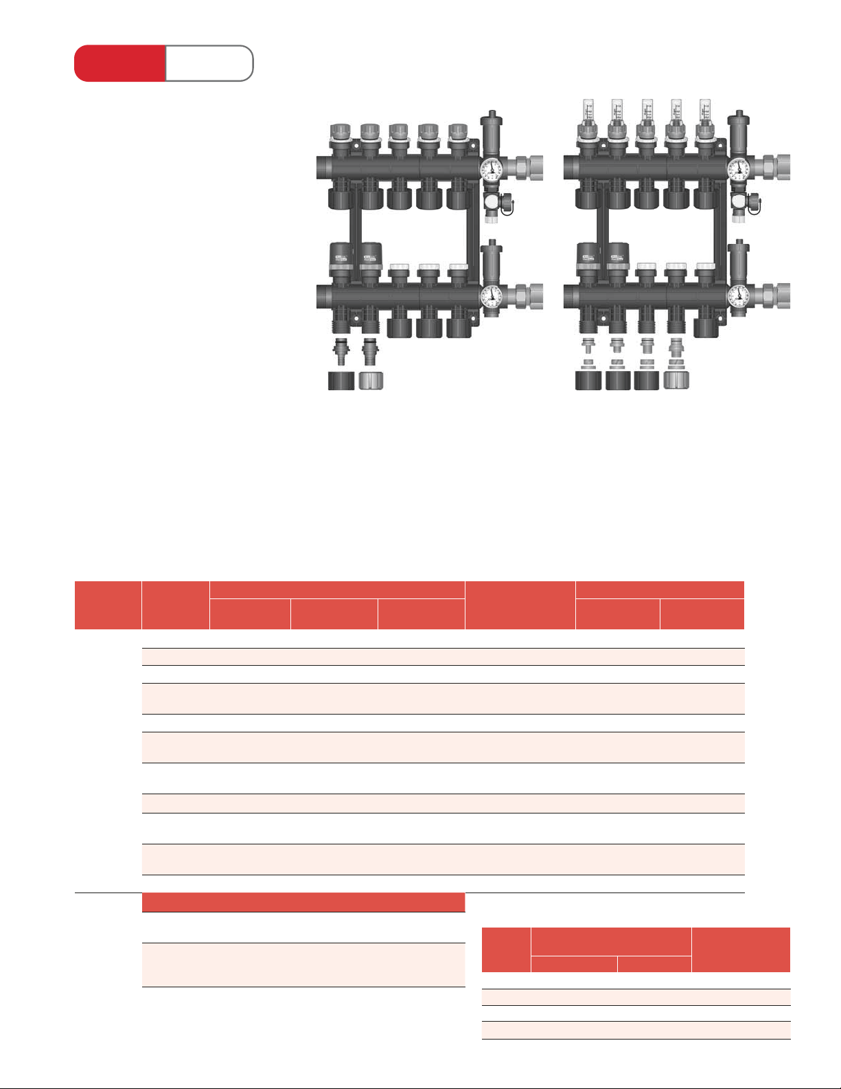
TwistSeal® Mini (40mm) Manifolds
Features & Bene ts :
• Modular “tool-less” assembly.
• Multiple con gurations from basic
to deluxe (all interchangeable; can
be recon gured on-site).
• Unlike a xed loop manifold,
loops can be added or removed as
required.
• Stock is exible, as there is no need
to stock xed-length manifolds.
Minimal SKUs on the shelf.
• Maximum trunk ow rate:
11 US gpm (2.5 m3/h)
• Maximum circuit ow rate:
78300 and 78320 series - 1 US gpm
(0.23 m3/h)
78200 - 1.25 US gpm (0.28 m3/h)
• 3⁄8", 1⁄2", 5⁄8", and 3⁄4" tubing to manifold
connecters available.
• Test rated to over 230 PSI @ 180°F
water temperature.
• 5 year limited warranty.
Typical Applications:
• Residential.
• Small commercial.
L to R
⁄2" & 3⁄4" PEX insert
tubing to manifold
connecters
(79200 assembly kit shown with 78322 and
78323 module pairs and 2 actuators)
7832x Module Speci c Features:
• Lockable balancing return.
• Zone valve supply with manual shut-o ;
accepts optional actuators.
L to R
⁄8", 1⁄2", 5⁄8", & 3⁄4"
tubing to manifold
connecters
(79200 assembly kit shown with 78302 and
78303 module pairs and 2 actuators)
7830x Module Speci c Features:
• Lockable balancing return with
0.4 - 1 US gpm (1.5 - 3.8 L/min) ow meter.
• Zone valve supply with manual shut-o ;
accepts optional actuators.
Assembly
Kit
79200
*recommended housing based on 79200 kit and 90° mains piping
# of Loops
2 2× 78200 1× 78322 1× 78302 - 71724 71424
3 3× 78200 1× 78323 1× 78303 - 71724 71424
4 4× 78200 2× 78322 2× 78302 - 71724 71424
5 5× 78200 1× 78322
6 6× 78200 2× 78323 2× 78303 1× 79892 71730 71430
7 7× 78200 2× 78322
8 8× 78200 1× 78322
9 9× 78200 3× 78323 3× 78303 2× 79892 71743 71442
10 10× 78200 2× 78322
11 11× 78200 1× 78322
12 12× 78200 4× 78323 4× 78303 3× 79892 71743 n/a
Actuator Selection
Actuator
with LED
Actuator
with End
Switch
Balancing
56200 56202 56202
56230 56232 56232
Choose Module Type
Multiport
Balancing
1× 78323
1× 78323
2× 78323
2× 78323
3× 78323
Multiport
Flow Meter
1× 78302
1× 78303
2× 78302
1× 78303
1× 78302
2× 78303
2× 78302
2× 78303
1× 78302
3× 78303
Recommended Housing*
Additional Brackets
- 71730 71430
1× 79892 71730 71442
1× 79892 71743 71442
2× 79892 71743 71442
2× 79892 71743 71442
Tubing
Size
Compression PEX Insert
⁄8" 77012 n/a 2× 86005
⁄2" 77005 2× 23015 2× 86005
⁄8" 77019 n/a 2× 86020
⁄4" 77022 2× 23032 2× 86022
Recessed Surface Mount
Tubing to Manifold
Connecters / Loop
Conduit Elbows
/ Loop for “Wet”
Installation
Page 14
Heat Link
www.heatlink.com
Radiant Heating & Cooling
Stk# Description Pkg Qty Carton Qty Unit List Price / Unit
79200
1" TwistSeal® Mini (40mm) Deluxe Manifold Assembly
®
TwistSeal® Mini (40 mm) Manifold Assembly Kits
Canada - July 1, 2014
TwistSeal® Mini (40 mm) Deluxe Manifold Assembly Kit
Stk# 79200
This package contains the items needed to assemble a mini deluxe heating
manifold. Contents include:
• 2 mounting brackets
• 2 - 1" union cross tee end connection c/w green bre gasket
• 2 - 1" MBSP × 1" FNPT adapter
• 2 red rubber gaskets for air testing
• 2 closed end caps
• 1 - 1⁄2" cross tee plug
• 1 thermometer pair
• 2 automatic air vents
• 1 hose bib
• 1 lubricant package
Kit
1 20 ea.
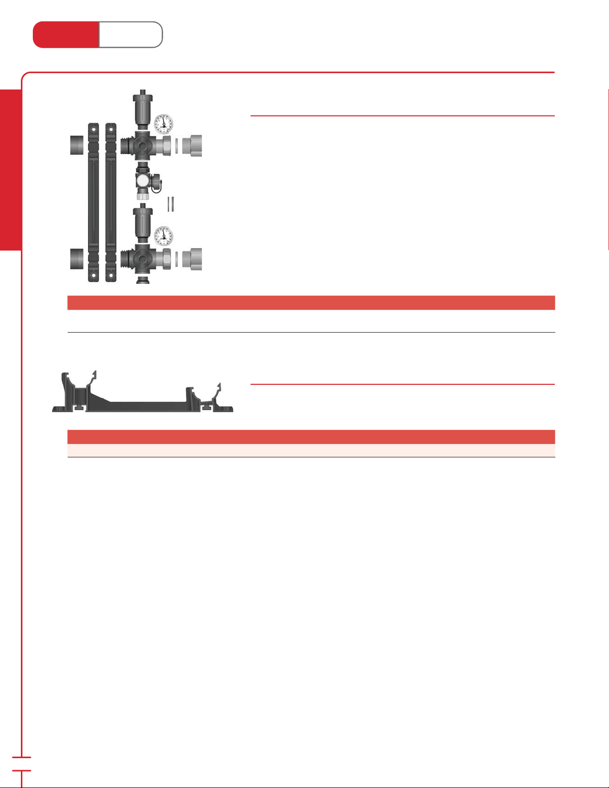
Mini Mounting Bracket (40 mm)
Stk# 79892
Plastic mounting bracket which allow easy ‘snap-on’ mounting of manifolds.
O set provides tubing passage behind 2nd manifold.
Stk# Description Pkg Qty Carton Qty Unit List Price / Unit
79892 TwistSeal® Multiport (40mm) Double Mounting Bracket 1 ea.
12
Page 15
Heat Link
www.heatlink.com
®
TwistSeal® Mini (40 mm) Manifold Modules
Canada - July 1, 2014
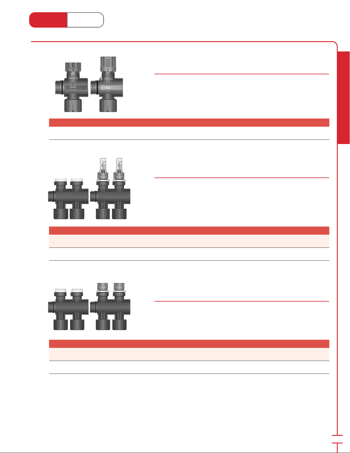
TwistSeal® Mini Deluxe (40 mm) Supply / Return Modules c/w Heavy
Duty Zone Valve Supply & Balancing Return
Stk# 78200
The supply module provides on/o manual control to allow isolation of individual
loops. The return module permits balancing of the ow rate with ow setting dial.
Comes with o-rings.
Stk# Description Pkg Qty Carton Qty Unit List Price / Unit
78200
TwistSeal® Mini Deluxe (40mm) Z.V. Supply & Balancing
Return Module Pair
1 10 pair
TwistSeal® Mini (40 mm) Multiport Zone Valve Supply & Flow
Meter Balancing Return Module Pair
78300 Series
The supply module provides on/o manual control to allow isolation of individual
loops. The return module permits visual balancing of the ow rate with the ow
meter. Comes with o-rings.
Radiant Heating & Cooling
Stk# Description Pkg Qty Carton Qty Unit List Price / Unit
78302
78303
TwistSeal® Mini (40mm) 2-port Z.V.Supply & Flow Meter
Return Module Pair
TwistSeal® Mini (40mm) 3-port Z.V.Supply & Flow Meter
Return Module Pair
1 6 pair
1 4 pair
TwistSeal® Mini (40 mm) Multiport Zone Valve Supply &
Balancing Return Module Pair
78320 Series
The supply module provides on/o manual control to allow isolation of individual
loops. The return module permits balancing of the ow rate. Comes with o-rings.
Stk# Description Pkg Qty Carton Qty Unit List Price / Unit
78322
78323
TwistSeal® Mini (40mm) 2-port Z.V.Supply & Flow Bal.
Return Module Pair
TwistSeal® Mini (40mm) 3-port Z.V.Supply & Flow Bal.
Return Module Pair
1 6 pair
1 4 pair
13
Page 16
Heat Link
3
1
5
3
1
3
www.heatlink.com
Stk# Description Pkg Qty Carton Qty Unit List Price / Unit
77012
77005
77019
Radiant Heating & Cooling
77022
⁄4" PEX to TwistSeal® Manifold Connecter c/w Nut 1 10 pair
®
TwistSeal® Manifold Accessories
Canada - July 1, 2014
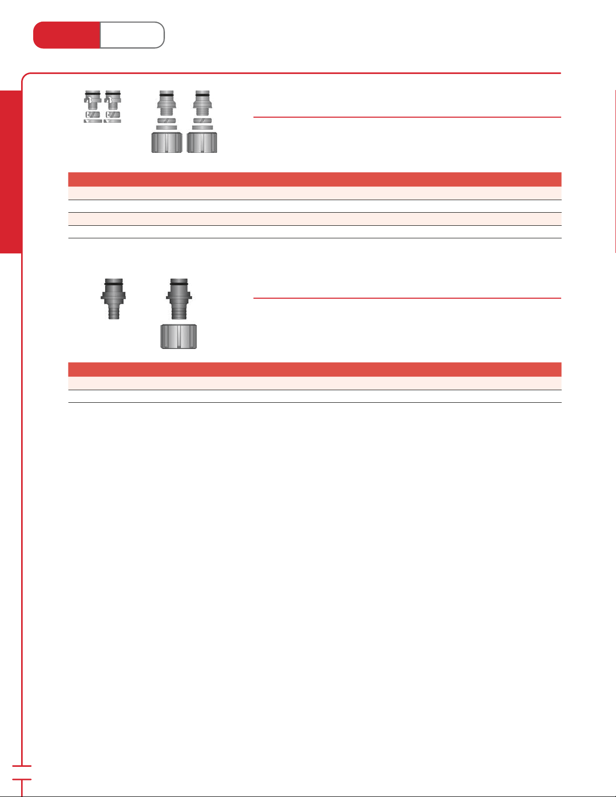
PEX Connecters for TwistSeal® Manifolds
77000 Series
Solid brass tting attaches to the end of the PEX tubing and allows for easy
installation onto the bottom of the manifold module. Comes with o-ring.
⁄8" PEX to TwistSeal® Manifold Connecter 1 10 pair
⁄2" PEX to TwistSeal® Manifold Connecter 1 10 pair
⁄8" PEX to TwistSeal® Manifold Connecter 1 10 pair
PEX Insert Connecters for TwistSeal® Manifold
23000 Series
Plastic tting is installed into the bottom of the manifold module and is held in
place by the nut. The tubing is then pressed on to this tting. Comes with o-ring.
SS press sleeves sold separately.
Stk# Description Pkg Qty Carton Qty Unit List Price / Unit
23015
23032
⁄2" PEX Insert Manifold Connecter 5 ea.
⁄4" PEX Insert Manifold Connecter c/w Nut 5 ea.
14
Page 17
®
76
200 Series
100 Series
1
5
3
1
Heat Link
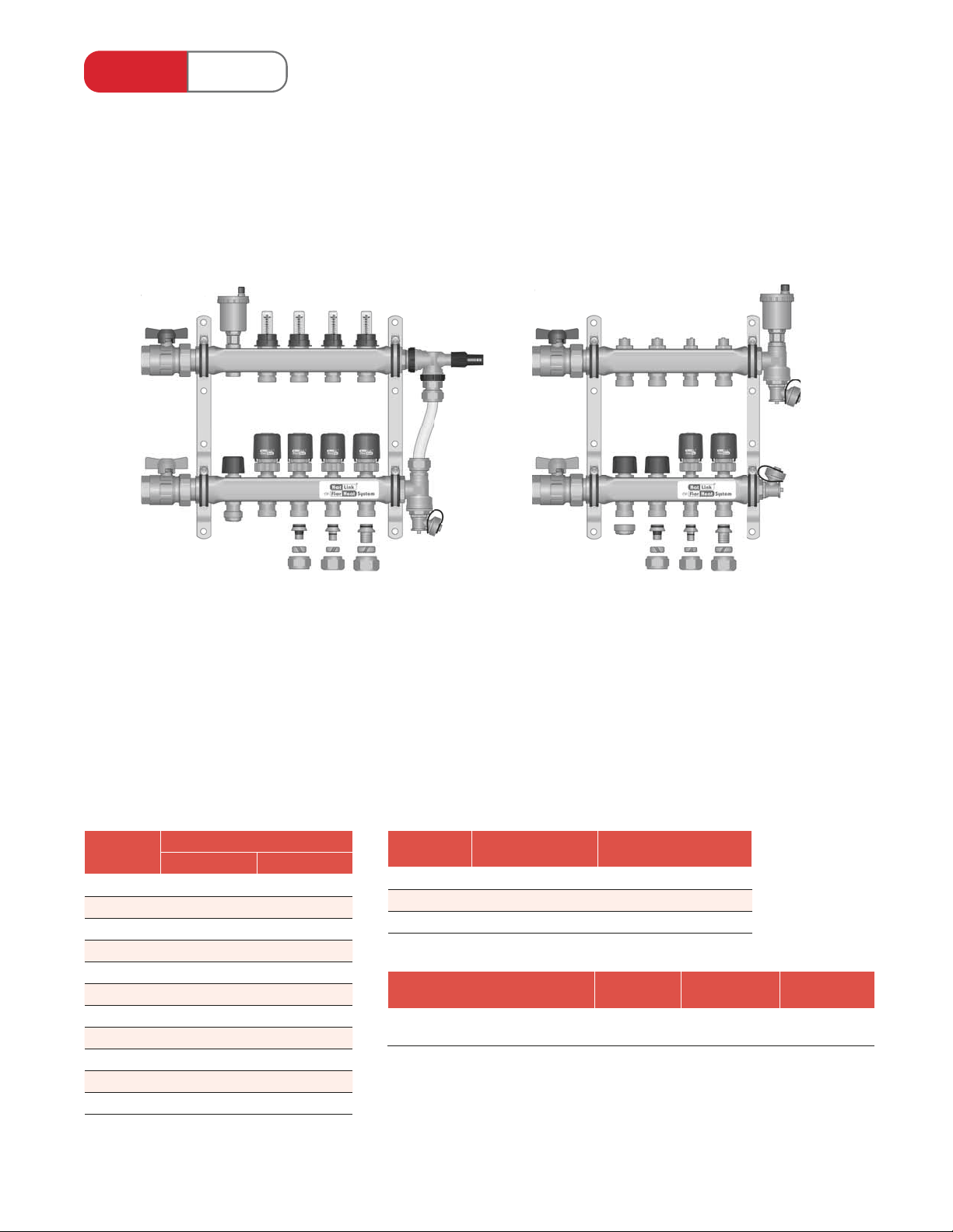
1-1⁄4" Stainless Steel Manifolds
Common Features:
• Preassembled con gurations from 2 to 12 loops.
• Integrated 1" FNPT isolation valves and hosebibs.
• Zone valve return balancing with manual shut-o ; accepts optional actuators.
• Maximum trunk ow rate: 18 US gpm (4.1 m3/h)
• 1⁄2", 5⁄8", and 3⁄4" PEX connecters available.
76100 Series 76200 Series
(76105 - 5 loop model shown with 4 actuators,
automatic air vent, 1⁄2" plug, port cap, and pressure
bypass valve)
Model Speci c Features:
• Maximum circuit ow rate: 1.5 US gpm (0.34 m3/h)
• Balancing supply with 0-1.5 US gpm (0-5 L/min)
ow meter.
Typical Applications:
• Residential.
• Small commercial.
# of Loops Recommended Housing*
Recessed Surface Mount
2 71724 71424
3 71724 71424
4 71730 71424
5 71730 71430
6 71730 71430
7 71743 71430
8 71743 71442
9 71743 71442
10 71743 71442
11 71743 71442
12 71743 71442
L to R
⁄2", 5⁄8", & 3⁄4" PEX
connecters
(76204 - 4 loop model shown with 2 actuators and
side mount automatic air vent)
Model Speci c Features:
• Maximum circuit ow rate: 2.5 US gpm (0.57m3/h)
• Balancing supply.
Typical Applications:
• Commercial.
• Snow melting.
Tubing Size PEX Connecters /
⁄2" 77105 2× 86005
⁄8" 77119 2× 86020
⁄4" 77122 2× 86022
Manifold Series Actuator
1-1⁄4" Stainless Steel
(76100 or 76200 series)
Loop
Conduit Elbows / Loop
for “Wet” Installation
with LED
56201 56231 56121
Actuator with
End Switch
L to R
port cap, 1⁄2", 5⁄8", & 3⁄4"
PEX connecters
DDC Actuator
*recommended housing based on 90° mains piping
Page 18
Heat Link
www.heatlink.com
®
1-1⁄4" Stainless Steel Manifolds
Canada - July 1, 2014
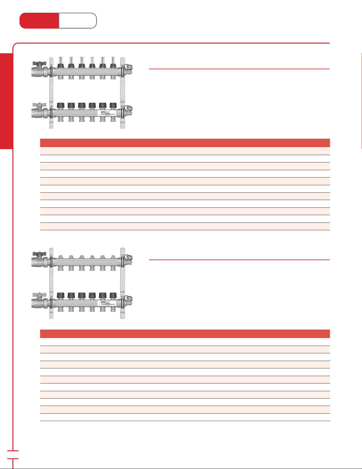
1-1⁄4" Stainless Steel Manifolds with Flow Meters
76100 Series
Manifold includes:
• 1 assembled ow balancing supply manifold with 1" FNPT isolation valve and
hose bib/air vent.
• 1 assembled balancing shut-o return manifold with 1" FNPT isolation valve
and hose bib/air vent.
• 2 mounting brackets.
PEX connecters & port caps sold separately.
Radiant Heating & Cooling
Stk# Description Pkg Qty Carton Qty Unit List Price / Unit
76102 2 Loop SS Manifold with Flow Meters 1 ea.
76103 3 Loop SS Manifold with Flow Meters 1 ea.
76104 4 Loop SS Manifold with Flow Meters 1 ea.
76105 5 Loop SS Manifold with Flow Meters 1 ea.
76106 6 Loop SS Manifold with Flow Meters 1 ea.
76107 7 Loop SS Manifold with Flow Meters 1 ea.
76108 8 Loop SS Manifold with Flow Meters 1 ea.
76109 9 Loop SS Manifold with Flow Meters 1 ea.
76110 10 Loop SS Manifold with Flow Meters 1 ea.
76111 11 Loop SS Manifold with Flow Meters 1 ea.
76112 12 Loop SS Manifold with Flow Meters 1 ea.
1-1⁄4" High Flow Stainless Steel Manifolds
76200 Series
Manifold includes:
• 1 assembled balancing supply manifold with 1" FNPT isolation valve and hose
bib/air vent.
• 1 assembled balancing shut-o return manifold with 1" FNPT isolation valve
and hose bib/air vent.
• 2 mounting brackets.
PEX connecters & port caps sold separately.
16
Stk# Description Pkg Qty Carton Qty Unit List Price / Unit
76202 2 Loop High Flow SS Manifold 1 ea.
76203 3 Loop High Flow SS Manifold 1 ea.
76204 4 Loop High Flow SS Manifold 1 ea.
76205 5 Loop High Flow SS Manifold 1 ea.
76206 6 Loop High Flow SS Manifold 1 ea.
76207 7 Loop High Flow SS Manifold 1 ea.
76208 8 Loop High Flow SS Manifold 1 ea.
76209 9 Loop High Flow SS Manifold 1 ea.
76210 10 Loop High Flow SS Manifold 1 ea.
76211 11 Loop High Flow SS Manifold 1 ea.
76212 12 Loop High Flow SS Manifold 1 ea.
Page 19
Heat Link
1
1
5
3
1
www.heatlink.com
®
1-1⁄4" Stainless Steel Manifold Accessories
Canada - July 1, 2014
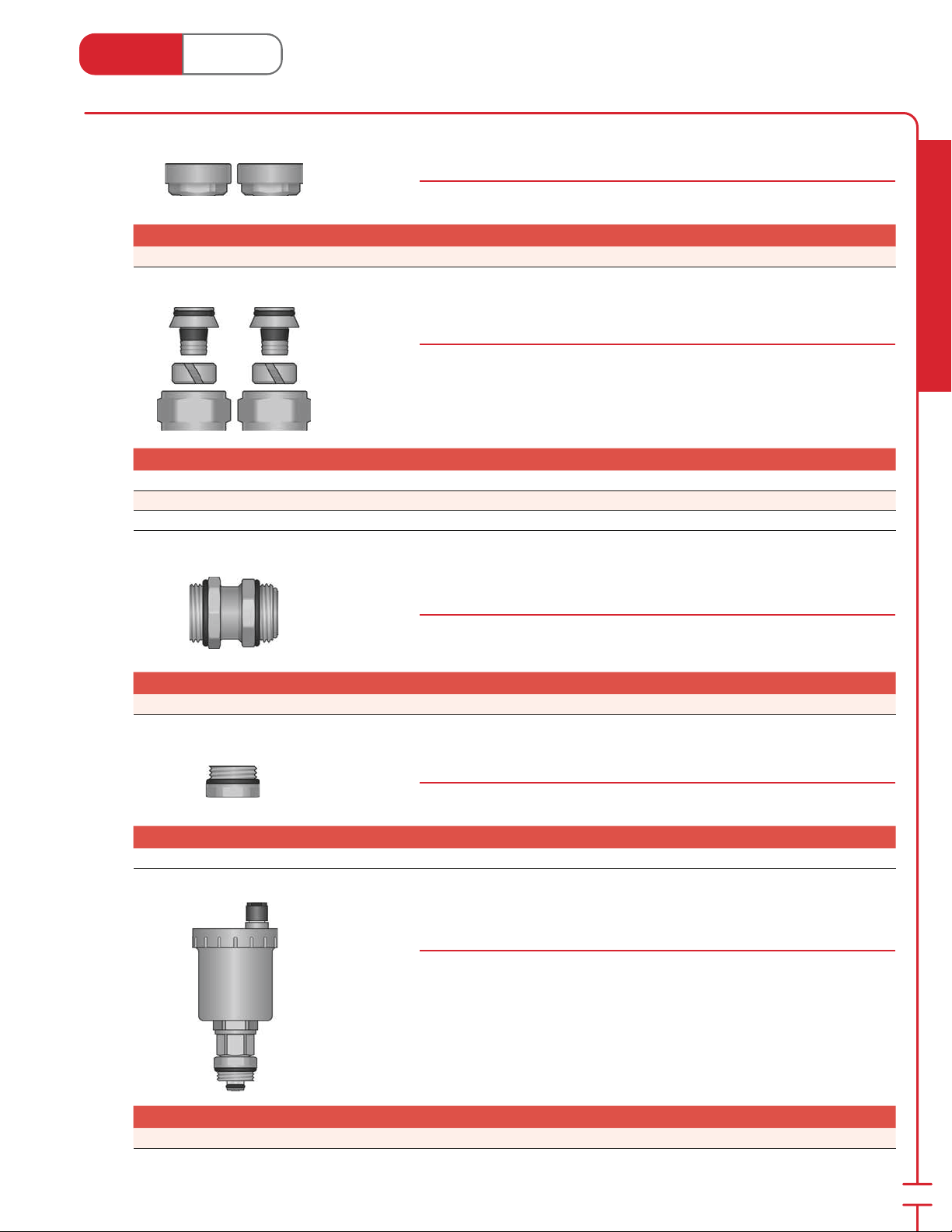
Port Caps for 1-1⁄4" Stainless Steel Manifolds
Stk# 77100
Caps o unused ports on the 1-1⁄4" Stainless Steel Manifold.
Stk# Description Pkg Qty Carton Qty Unit List Price / Unit
77100 Port Cap for 1-1⁄4" SS Manifold 1 10 pair
PEX Connecters for 1-1⁄4" Stainless Steel Manifolds
77100 Series
Solid brass tting attaches to the end of the PEX tubing and allows for easy
installation onto the bottom of the 1-1⁄4" SS manifold. Comes with o-ring.
Stk# Description Pkg Qty Carton Qty Unit List Price / Unit
77105
77119
77122
⁄2" PEX to 1-1⁄4" SS Manifold Connecter 1 10 pair
⁄8" PEX to 1-1⁄4" SS Manifold Connecter 1 10 pair
⁄4" PEX to 1-1⁄4" SS Manifold Connecter 1 10 pair
Coupling for 1-1⁄4" Stainless Steel Manifold
Stk# 76100
Radiant Heating & Cooling
Used to connect 1-1⁄4" SS manifolds together. Comes with o-rings.
Stk# Description Pkg Qty Carton Qty Unit List Price / Unit
76100 Coupling for SS Manifold 1 ea.
⁄2" Plug for 1-1⁄4" Stainless Steel Manifold
Stk# 76905
Plug to seal 1-1⁄4" SS manifold outlet. Comes with o-ring.
Stk# Description Pkg Qty Carton Qty Unit List Price / Unit
76905
⁄2" Plug for 1-1⁄4" SS Manifold 1 ea.
Automatic Air Vent for 1-1⁄4" Stainless Steel Manifold
Stk# 76932
Add an automatic air vent to the 1-1⁄4" SS manifold by replacing a valve. Comes
with o-ring.
Stk# Description Pkg Qty Carton Qty Unit List Price / Unit
76932 Automatic Air Vent for 1-1⁄4" SS Manifold 1 ea.
17
Page 20
Heat Link
www.heatlink.com
®
1-1⁄4" Stainless Steel Manifold Accessories
Canada - July 1, 2014
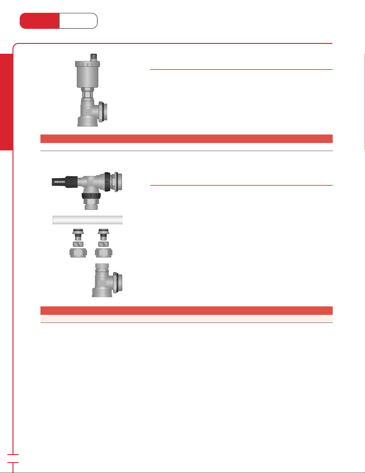
Side Mount Automatic Air Vent Set for 1-1⁄4" Stainless Steel Manifold
Stk# 76935
Add an automatic air vent to the 1-1⁄4" SS manifold without occupying a loop.
Comes with o-ring.
Side Mount Automatic Air Vent is not compatible with the Pressure Bypass Kit
(#76937).
Radiant Heating & Cooling
Stk# Description Pkg Qty Carton Qty Unit List Price / Unit
76935 Side Mount Automatic Air Vent Set for 1-1⁄4" SS Manifold 1 ea.
Stk# Description Pkg Qty Carton Qty Unit List Price / Unit
76937 Pressure Bypass Kit for 1-1⁄4" SS Manifold 1 ea.
Pressure Bypass Kit for 1-1⁄4" Stainless Steel Manifold
Stk# 76937
This valve prevents a steep rise of the pump head and maintains ow at a stable
rate. Also ensures only required amount of cir cu lat ing water is used for hydronic
systems. The valve can be ad just ed to any point between 0.05 and 0.5 bar (1.67
and 16.7 ft H2O). Comes with o-rings.
Pressure Bypass Kit is not compatible with the Side Mount Automatic Air Vent Set
(#76935).
18
Page 21
Heat Link
www.heatlink.com
®
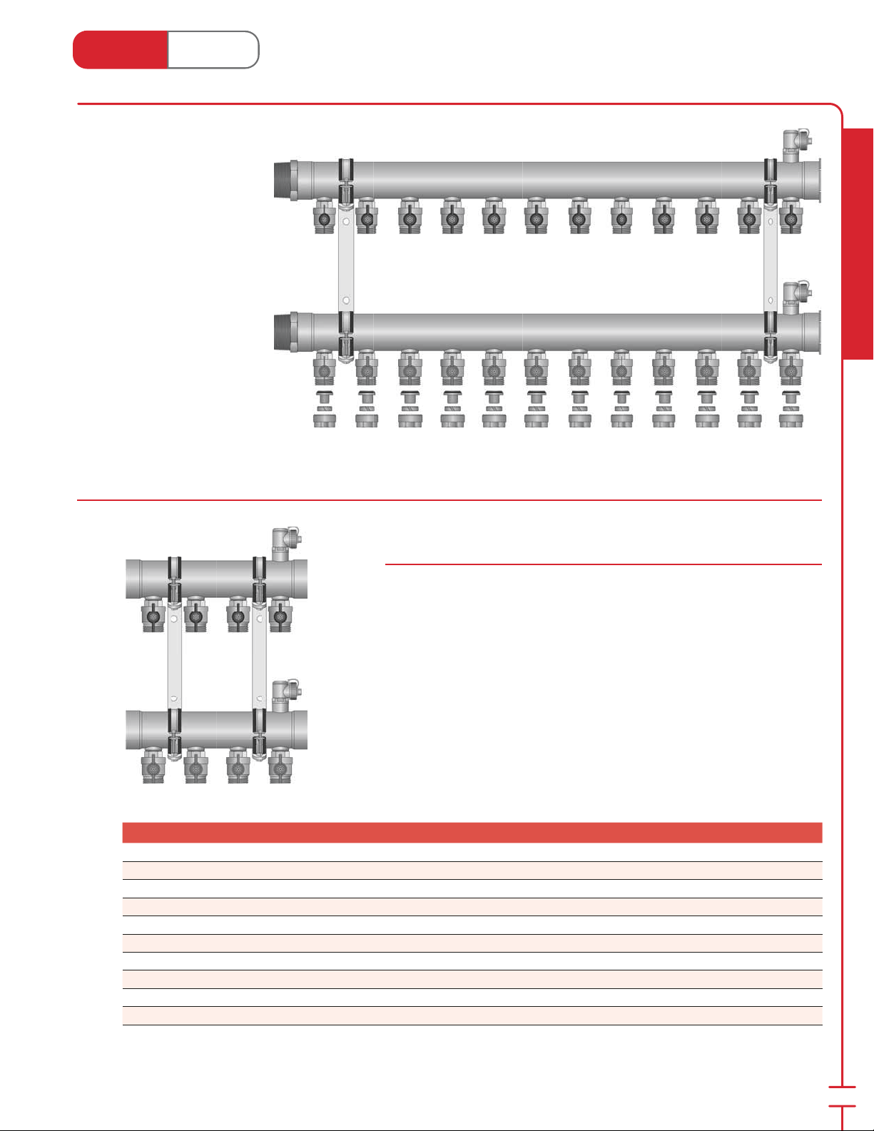
2" Stainless Steel Manifold
Canada - July 1, 2014
Features:
• Preassembled
con gurations from 4 to 14
loops.
• Ball valve isolation for each
loop.
• 1-1⁄2" and 2" MNPT open end
adapters.
• Maximum trunk ow rate:
50 US gpm (11.4 m3/h).
• Branch pair Cv = 6.
• 5⁄8", 3⁄4", and 1" PEX
connecters.
Typical Applications:
• Large commercial.
• Snow melting.
• Distribution header.
Radiant Heating & Cooling
(76612 - 12 loop model shown with 2" MNPT Assembly Kit, and 3⁄4" PEX connecters)
2" Stainless Steel Manifolds
76600 Series
Manifold includes:
• 1 assembled supply manifold with ball valves and hose bib/air vent.
• 1 assembled return manifold with ball valves and hose bib/air vent.
• 2 mounting brackets.
Assembly Kit and PEX connecters sold separately.
Stk# Description Pkg Qty Carton Qty Unit List Price / Unit
76604 4 Loop 2" SS Manifold 1 ea.
76605 5 Loop 2" SS Manifold 1 ea.
76606 6 Loop 2" SS Manifold 1 ea.
76607 7 Loop 2" SS Manifold 1 ea.
76608 8 Loop 2" SS Manifold 1 ea.
76609 9 Loop 2" SS Manifold 1 ea.
76610 10 Loop 2" SS Manifold 1 ea.
76611 11 Loop 2" SS Manifold 1 ea.
76612 12 Loop 2" SS Manifold 1 ea.
76614 14 Loop 2" SS Manifold 1 ea.
19
Page 22
Heat Link
5
3
www.heatlink.com
Stk# Description Pkg Qty Carton Qty Unit List Price / Unit
76600 Coupling for 2" SS Manifold 1 pair
®
2" Stainless Steel Manifold Accessories
Canada - July 1, 2014
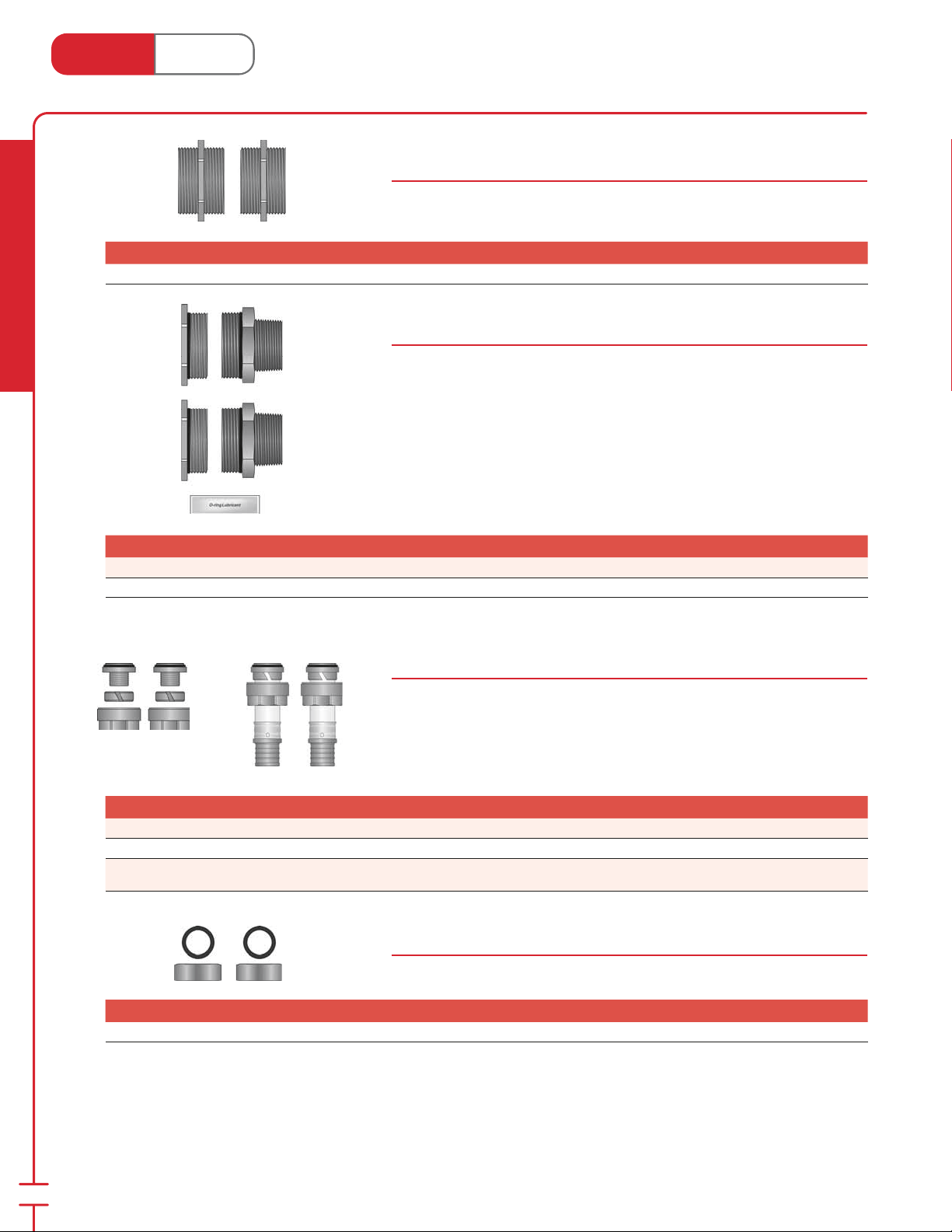
Coupling for 2" SS Manifold
Stk# 76600
Couple 2" SS Manifolds together. Loctite 55 pipe sealing cord is recommended for
thread sealing (not included).
Assembly Kits for 2" Stainless Steel Manifold
Stk# 76800 Series
Radiant Heating & Cooling
Stk# Description Pkg Qty Carton Qty Unit List Price / Unit
New!
New!
New!
New!
Special
Order*
76840 1-1⁄2" MNPT Assembly Kit for 2" SS Manifold 1 ea.
76850 2" MNPT Assembly Kit for 2" SS Manifold 1 ea.
77622 77628
Stk# Description Pkg Qty Carton Qty Unit List Price / Unit
77619
77622
77628 1" PEX to 2" SS Manifold Connecter 1 pair
Assembly Kit includes:
• 2 Closed Ends for 2" SS Manifold with o-ring.
• 2 Open End Adapters (1-1⁄2" or 2" MNPT) for 2" SS Manifold with o-ring.
• 1 packet of lubricant.
PEX Connecters for 2" Stainless Steel Manifold
Stk# 77600 Series
Solid brass tting attaches to the end of the PEX tubing and allows for easy
installation onto the shut-o valves of the 2" SS manifold. Comes with o-ring.
1" connecters require 1" SS Press Sleeves (#24228; page 126) and use of a 1"
Press Tool (e.g. 11328).
⁄8" PEX to 2" SS Manifold Connecter 1 pair
⁄4" PEX to 2" SS Manifold Connecter 1 pair
20
New!
1" Cap and Washer for 2" Stainless Steel Manifold
Stk# 76675
Cap to seal 2" SS manifold outlet.
Stk# Description Pkg Qty Carton Qty Unit List Price / Unit
76675 1" Cap and Washer for 2" SS Manifold 1 pair
* Check with your local representative for availability.
Page 23
Manifold
Housings
7
Heat Link
Features & Bene ts
;
;
;
;
;
;
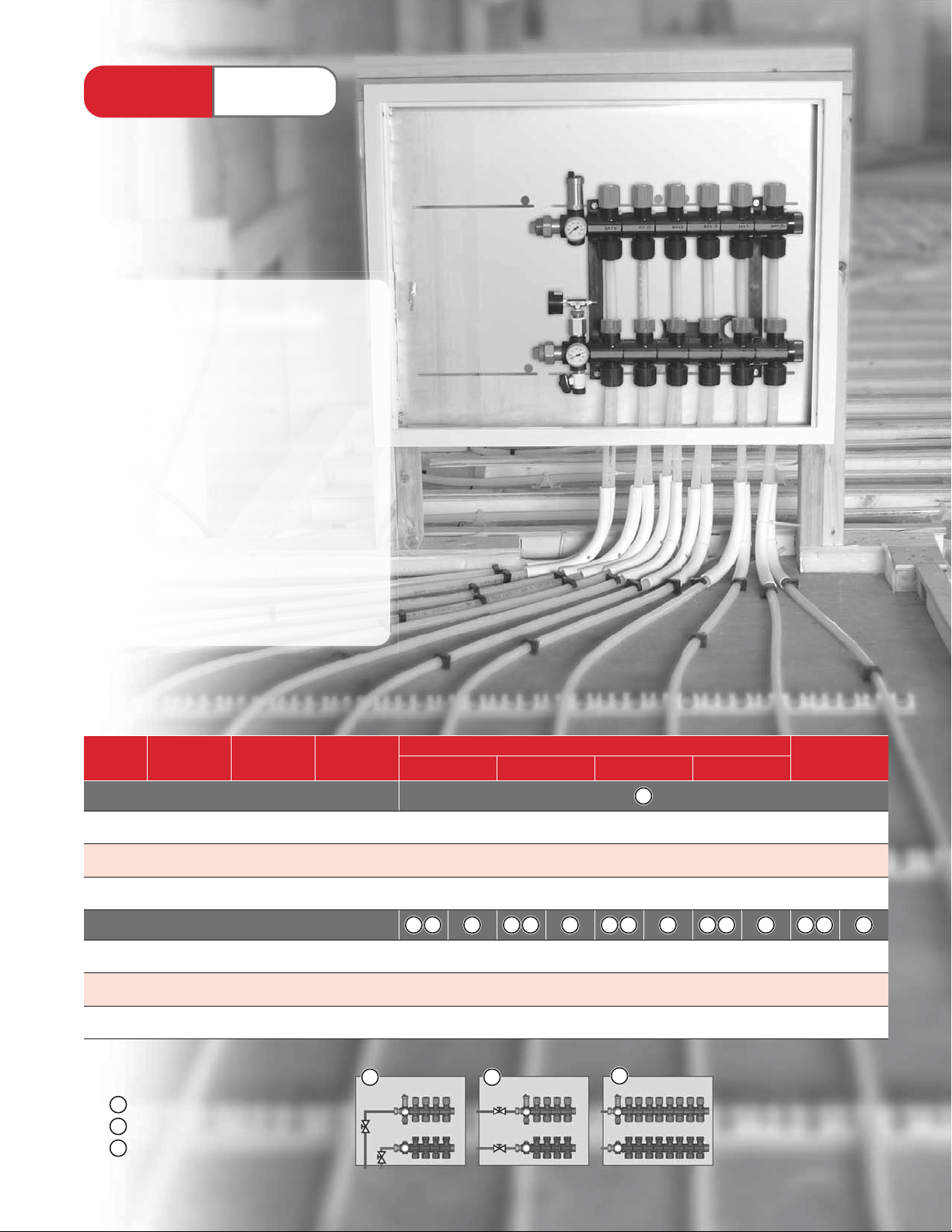
Manifold
Housings
Features & Bene ts
allows easy access to manifold
;
visible parts made of satin coated
;
steel and are ready to paint without
priming
cover enables a structural ush seal
;
locking, removable (lift o ) door
;
stylish ventilation apertures to
;
prevent build up of heat and
formation of condensation
®
openings for mains piping on left &
;
right sides (recessed only)
Stk. # Width Height Depth
71400 Series: Surface Mounted Manifold Housing
71424
71430
71442
71700 Series: Recessed Manifold Housing
71724
71730
71743
24"
(610 mm)
30"
(762 mm)
42"
(1067 mm)
24"
(610 mm)
30-1⁄4"
(768 mm)
43-1⁄2"
(1105 mm)
30"
(762 mm)
30"
(762 mm)
30"
(762 mm)
23"
(584 mm)
23"
(584 mm)
23"
(584 mm)
5-1⁄2"
(140 mm)
5-1⁄2"
(140 mm)
5-1⁄2"
(140 mm)
⁄8"
3-
(98 mm)
3-7⁄8"
(98 mm)
3-7⁄8"
(98 mm)
Maximum # of Loops with Manifold Assembly Kit #: Max # of
79400* 79401* 79402* 79200
1
45344
77667
11 12 10 11 12
1 2 3 1 2 3 1 2 3 1 2 3 1 2 3
4 7 5 8 3 6 4 8 3 7
6 9 7 10 5 8 7 10 6 7
11 12 12 12 10 12 12 12 12 12
SS Manifold
Loops
Installation Methods:
1
Allowance for 90˚ mains piping.
2
Allowance for straight isolation valves.
3
Manifolds only, no piping allowances.
* Thermometers must be removed in recessed housing.
21
3
Page 24
Heat Link
7
1
1
1
www.heatlink.com
Radiant Heating & Cooling
Stk# Description Pkg Qty Carton Qty Unit List Price / Unit
71724 Recessed Manifold Housing 24"×23"×3-7⁄8" 1 ea.
71730 Recessed Manifold Housing 30"×23"×3-
71743 Recessed Manifold Housing 43-
®
Manifold Housings
Canada - July 1, 2014
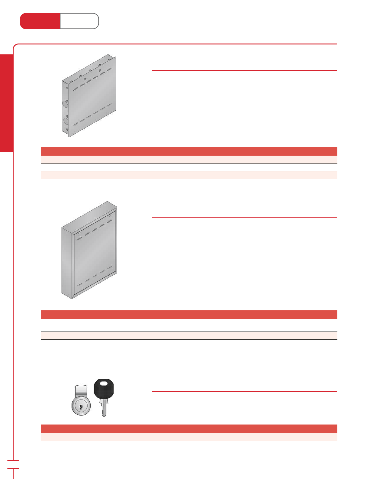
Manifold Housing: Recessed
71700 Series
Allows easy access to the manifold through its locking, removable door.
Features: visible parts made of satin coated steel, surfaces ready to paint without
priming, and stylish ventilation apertures to prevent build up of heat and
formation of condensation.
For use with TwistSeal® and Stainless Steel Manifolds (76100 and 76200 series).
Not compatible with 2" Stainless Steel Manifolds (76600 series).
⁄8" 1 ea.
⁄2"×23"×3-7⁄8" 1 ea.
Special
Pricing
Manifold Housing: Surface Mount
71400 Series
Allows easy access to the manifold through its locking, removable door.
Features: made of satin coated steel, surfaces ready to paint without priming,
and stylish ventilation apertures to prevent build up of heat and formation of
condensation. Skirting by others.
For use with TwistSeal® and Stainless Steel Manifolds (76100 and 76200 series).
Not compatible with 2" Stainless Steel Manifolds (76600 series).
Stk# Description Pkg Qty Carton Qty Unit List Price / Unit
71424 Surface Mounted Manifold Housing 24"×30"×5-1⁄2" 1 ea.
71430 Surface Mounted Manifold Housing 30"×30"×5-
71442 Surface Mounted Manifold Housing 42"×30"×5-
⁄2" 1 ea.
⁄2" 1 ea.
Key Lock for Manifold Housing Door
Stk# 71902
22
Key lock that can eld replace the standard coin/screwdriver lock of manifold
housings (71700 and 71400 Series).
Stk# Description Pkg Qty Carton Qty Unit List Price / Unit
71902 Key Lock for Housing Door 1 ea.
Page 25
Heat Link
3
1
5
3
3
1
5
3
www.heatlink.com
®
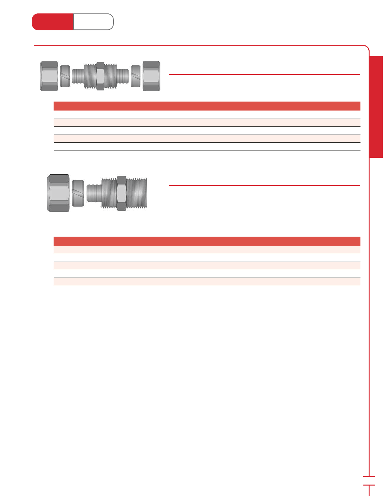
PEX Compression Couplings & Adapters
Canada - July 1, 2014
PEX Tubing Compression Couplings
69000 Series
Solid brass ttings couples PEX tubing to PEX tubing.
Stk# Description Pkg Qty Carton Qty Unit List Price / Unit
69012
69005
69019
69022
69028 1" × 1" PEX Comp. Coupling 1 25 ea.
⁄8" × 3⁄8" PEX Comp. Coupling 1 25 ea.
⁄2" × 1⁄2" PEX Comp. Coupling 1 25 ea.
⁄8" × 5⁄8" PEX Comp. Coupling 1 25 ea.
⁄4" × 3⁄4" PEX Comp. Coupling 1 25 ea.
PEX Compression to MNPT Adapters
68000 Series
Solid brass ttings converts PEX tubing to male NPT thread.
Note: When used with PEX tubing there is a risk of thermal expansion /
contraction due to temperature uctuation. It is recommended that a
swing joint or expansion loop is installed at the high temp (supply) end of
the tubing.
Stk# Description Pkg Qty Carton Qty Unit List Price / Unit
68012
68005
68019
68022
68028 1" PEX Comp. × 1" MNPT Adapter 1 25 ea.
⁄8" PEX Comp. × 1⁄2" MNPT Adapter 1 25 ea.
⁄2" PEX Comp. × 1⁄2" MNPT Adapter 1 25 ea.
⁄8" PEX Comp. x 3⁄4" MNPT Adapter 1 25 ea.
⁄4" PEX Comp. × 3⁄4" MNPT Adapter 1 25 ea.
Radiant Heating & Cooling
23
Page 26
Heat Link
1
1
5
1
1
5
1
5
3
www.heatlink.com
Stk# Description Pkg Qty Carton Qty Unit List Price / Unit
67305
Radiant Heating & Cooling
67705
67319
®
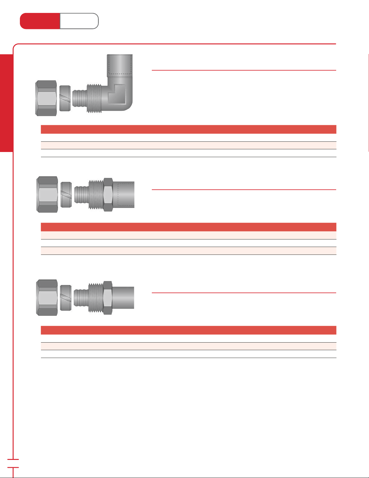
PEX Compression Adapters
Canada - July 1, 2014
PEX Compression to 90˚ Female Sweat Elbows
67300 & 67700 Series
Solid brass ttings converts PEX tubing to female copper pipe.
Ideal for baseboard connections.
⁄2" PEX Comp. × 1⁄2" F/Sweat 90° Elbow 1 25 ea.
⁄2" PEX Comp. × 3⁄4" F/Sweat 90° Elbow 1 25 ea.
⁄8" PEX Comp. × 3⁄4" F/Sweat 90° Elbow 1 25 ea.
PEX Compression to Female Sweat Adapters
67100 & 67500 Series
Solid brass ttings converts PEX tubing to female copper pipe.
Stk# Description Pkg Qty Carton Qty Unit List Price / Unit
67105
67505
67119
⁄2" PEX Comp. × 1⁄2" F/Sweat Adapter 1 25 ea.
⁄2" PEX Comp. × 3⁄4" Straight F/Sweat Adapter 1 25 ea.
⁄8" PEX Comp. × 3⁄4" F/Sweat Adapter 1 25 ea.
PEX Compression to Male Sweat Adapters
67000 Series
Solid brass ttings converts PEX tubing to male copper pipe.
Stk# Description Pkg Qty Carton Qty Unit List Price / Unit
67005
67019
67022
⁄2" PEX Comp. × 1⁄2" M/Sweat Adapter 1 25 ea.
⁄8" PEX Comp. × 3⁄4" M/Sweat Adapter 1 25 ea.
⁄4" PEX Comp. × 3⁄4" M/Sweat Adapter 1 25 ea.
Note: For 1⁄2", 3⁄4", 1", 1-1⁄4", and 1-1⁄2" PEX tubing the SS press sleeve tting system can be used, see the ”Potable Water System” section.
24
Page 27
Heat Link
www.heatlink.com
®
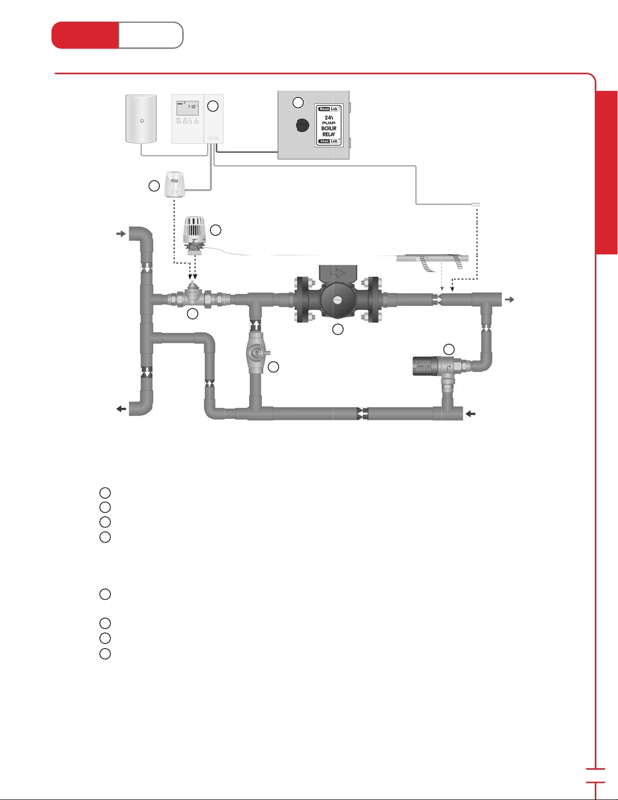
2-way Injection Mixing
Canada - July 1, 2014
Primary
Supply
6
8
5
1
7
Secondary
Supply
3
4
2
Radiant Heating & Cooling
Primary
Return
Components
1
HeatLink® Injection Valve (62000 series; page 33)
2
HeatLink® Balancing Valve (#62325; page 32)
3
Secondary Pump
HeatLink® Pressure Activated Bypass Valve (60000 series; page 34)
4
Control Options
Setpoint
5
HeatLink® Thermostatic Head with Capillary (#57094; page 36)
Setpoint or Outdoor Reset
6
HeatLink® Compact Mixing Reset Control (#31355; page 44)
7
HeatLink® 24Vac DPDT Pump Relay (#45112; page 42)
HeatLink® DDC Actuator (#56121; page 37)
8
Secondary
Return
Note: Not all required components are shown. Local codes, regulation, and authorities have nal jurisdiction.
25
Page 28
Heat Link
www.heatlink.com
®
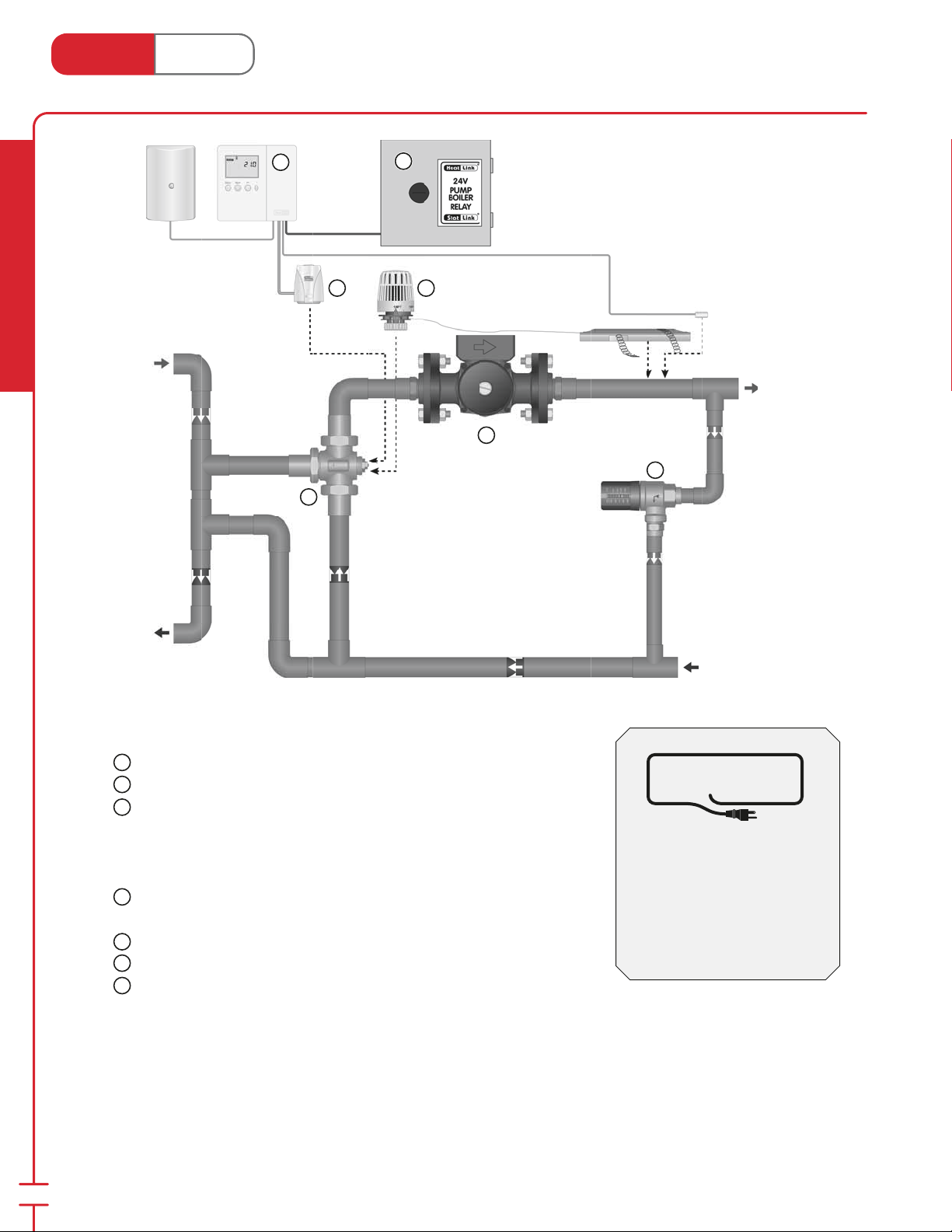
3-way Compact Mixing System
Canada - July 1, 2014
Radiant Heating & Cooling
Primary
Supply
5
7
1
6
4
Secondary
Supply
2
3
Primary
Return
Components
1
HeatLink® Compact 3-way Mixing Valve (63700 series; page 31)
2
Secondary Pump
3
HeatLink® Pressure Activated Bypass Valve (60000 series; page 34)
Control Options
Setpoint
4
HeatLink® Thermostatic Head with Capillary (#57094; page 36)
Setpoint or Outdoor Reset
HeatLink® Compact Mixing Reset Control (#31355; page 44)
5
6
HeatLink® 24Vac DPDT Pump Relay (#45112; page 42)
7
HeatLink® DDC Actuator (#56121; page 37)
Note: Not all required components are shown. Local codes, regulation, and authorities have nal jurisdiction.
Secondary
Return
™
MECHANICAL
ROOM IN A BOX
Panel Alternatives
TMP series - pages 72-79
TWH series - pages 80-85
CDP series - pages 92-95
SSTS series - pages 104-105
26
Page 29
Heat Link
www.heatlink.com
®
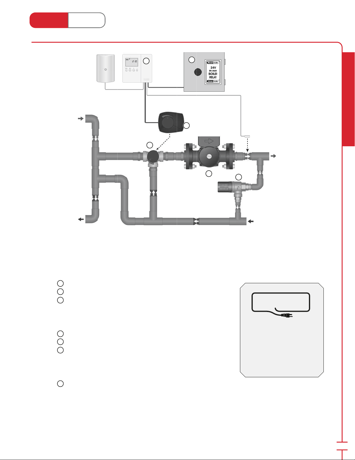
3-way Mixing System
Canada - July 1, 2014
Primary
Supply
Primary
Return
4
1
5
6
Secondary
Supply
2
3
Secondary
Return
Radiant Heating & Cooling
Components
1
HeatLink® 3-way Mixing Valve (63500 series; page 30)
2
Secondary Pump
3
HeatLink® Pressure Activated Bypass Valve (60000 series; page 34)
MECHANICAL
ROOM IN A BOX
Control Options
Setpoint or Outdoor Reset
HeatLink® Compact Mixing Reset Control (#31355; page 44)
4
5
HeatLink® 24Vac DPDT Pump Relay (#45112; page 42)
6
HeatLink® Mixing Valve Motor (58100 series; page 35)
Snow melt (not shown)
HeatLink® Snow/Ice Detector & Melting Control (#31667; page 45)
HeatLink® Snow/Ice Detector (#30090, 30091; page 45)
6
HeatLink® Mixing Valve Motor (58100 series; page 35)
Note: Not all required components are shown. Local codes, regulation, and authorities have nal jurisdiction.
Panel Alternatives
CDP310R - pages 96-97
SSTL series - pages 106-107
SMP series - pages 108-116
™
27
Page 30
Heat Link
www.heatlink.com
®
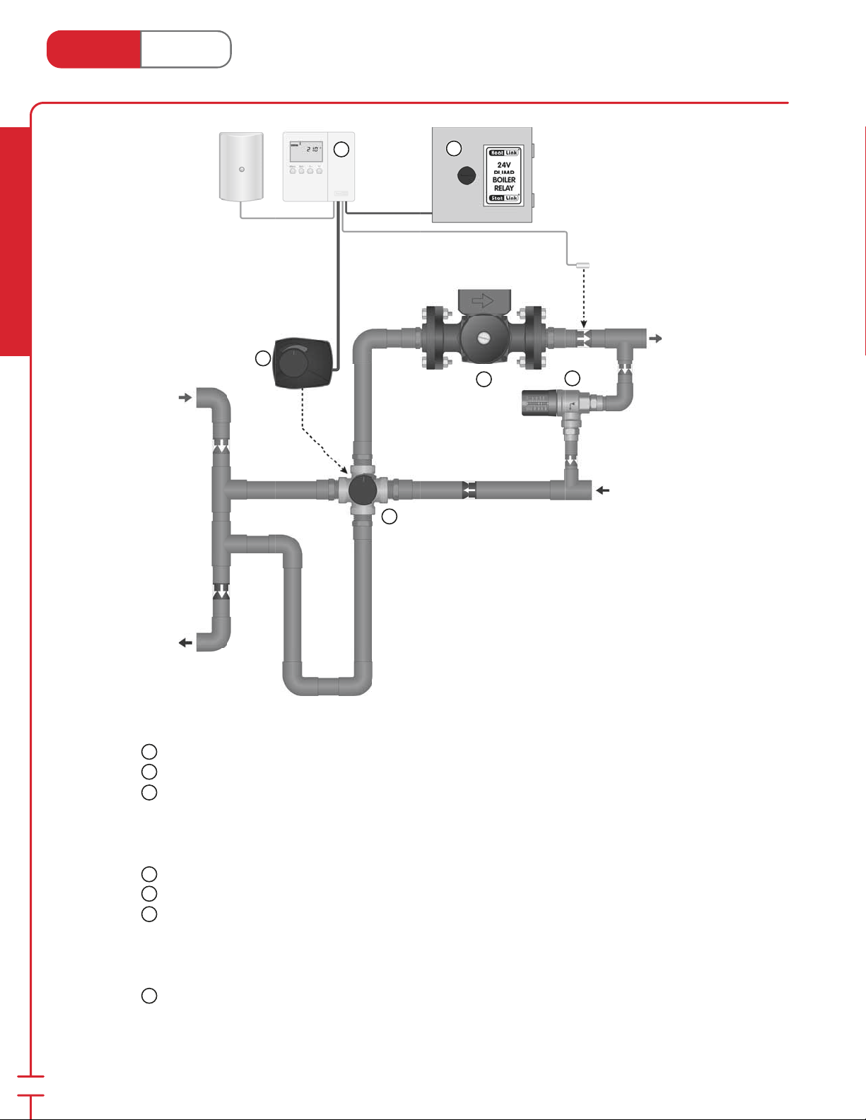
4-way Mixing System
Canada - July 1, 2014
Radiant Heating & Cooling
Primary
Supply
4
6
1
5
Secondary
Supply
2
3
Secondary
Return
Primary
Return
Components
1
HeatLink® 4-way Mixing Valve (64000 series; page 30)
2
Secondary Pump
3
HeatLink® Pressure Activated Bypass Valve (60000 series; page 34)
Control Options
Setpoint or Outdoor Reset
HeatLink® Compact Mixing Reset Control (#31355; page 44)
4
5
HeatLink® 24Vac DPDT Pump Relay (#45112; page 42)
6
HeatLink® Mixing Valve Motor (58100 series; page 35)
Snow melt (not shown)
HeatLink® Snow/Ice Detector & Melting Control (#31667; page 45)
HeatLink® Snow/Ice Detector (#30090, 30091; page 45)
6
HeatLink® Mixing Valve Motor (58100 series; page 35)
Note: Not all required components are shown. Local codes, regulation, and authorities have nal jurisdiction.
28
Page 31
Heat Link
www.heatlink.com
®
Mixing Valves
Canada - July 1, 2014
New!
New!
New!
New!
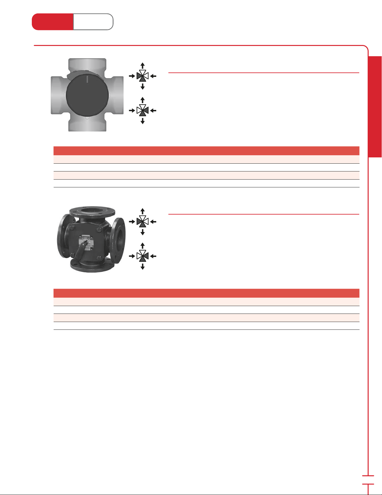
4-way FNPT Mixing Valves
64000 Series
This unit mixes high temperature boiler water with heating return water to create
a supply water temperature. It has the option of manual op er a tion, or it can be
tted with a Mixing Valve Motor for 1" to 2" FNPT Valves 3-Point Floating (#58131;
page 35) or Mixing Valve Motor for 1" to 2" FNPT Valves DDC (#58132; page
35) for fully automatic operation.
1" Cv = 11.7 (Kvs = 10)
1-1⁄4" Cv = 18.7 (Kvs = 16)
1-1⁄2" Cv = 29.3 (Kvs = 25)
2" Cv = 46.8 (Kvs = 40)
Stk# Description Pkg Qty Carton Qty Unit List Price / Unit
64026 1" × 4-way FNPT Mixing Valve 1 ea.
64031 1-1⁄4" × 4-way FNPT Mixing Valve 1 ea.
64041 1-1⁄2" × 4-way FNPT Mixing Valve 1 ea.
64051 2" × 4-way FNPT Mixing Valve 1 ea.
4-Way Flange Mixing Valves
64100 Series
This unit mixes high temperature boiler water with heating return water to
create a supply water temperature. It has the option of manual op er a tion, or it
can be tted with a Mixing Valve Motor for 2" to 4" Flange Valves 3-Point Floating
(#58200; page 35) or Mixing Valve Motor for 2" to 4" Flange Valves DDC (#58300;
page 35) for fully automatic operation. Flange are DIN compatible.
2" Cv = 69.4 (Kvs = 60)
2-1⁄2" Cv = 104.0 (Kvs = 90)
3" Cv = 173.4 (Kvs = 150)
4" Cv = 260.1 (Kvs = 225)
Radiant Heating & Cooling
New!
New!
New!
New!
Stk# Description Pkg Qty Carton Qty Unit List Price / Unit
64164 2" × 4-way Flange Mixing Valve 1 ea.
64166 2-1⁄2" × 4-way Flange Mixing Valve 1 ea.
64181 3" × 4-way Flange Mixing Valve 1 ea.
65000 4" × 4-way Flange Mixing Valve 1 ea.
29
Page 32
Heat Link
1
www.heatlink.com
Stk# Description Pkg Qty Carton Qty Unit List Price / Unit
WSL
64030 1-1⁄4" × 4-way FNPT Mixing Valve 1 ea.
®
Mixing Valves
Canada - July 1, 2014
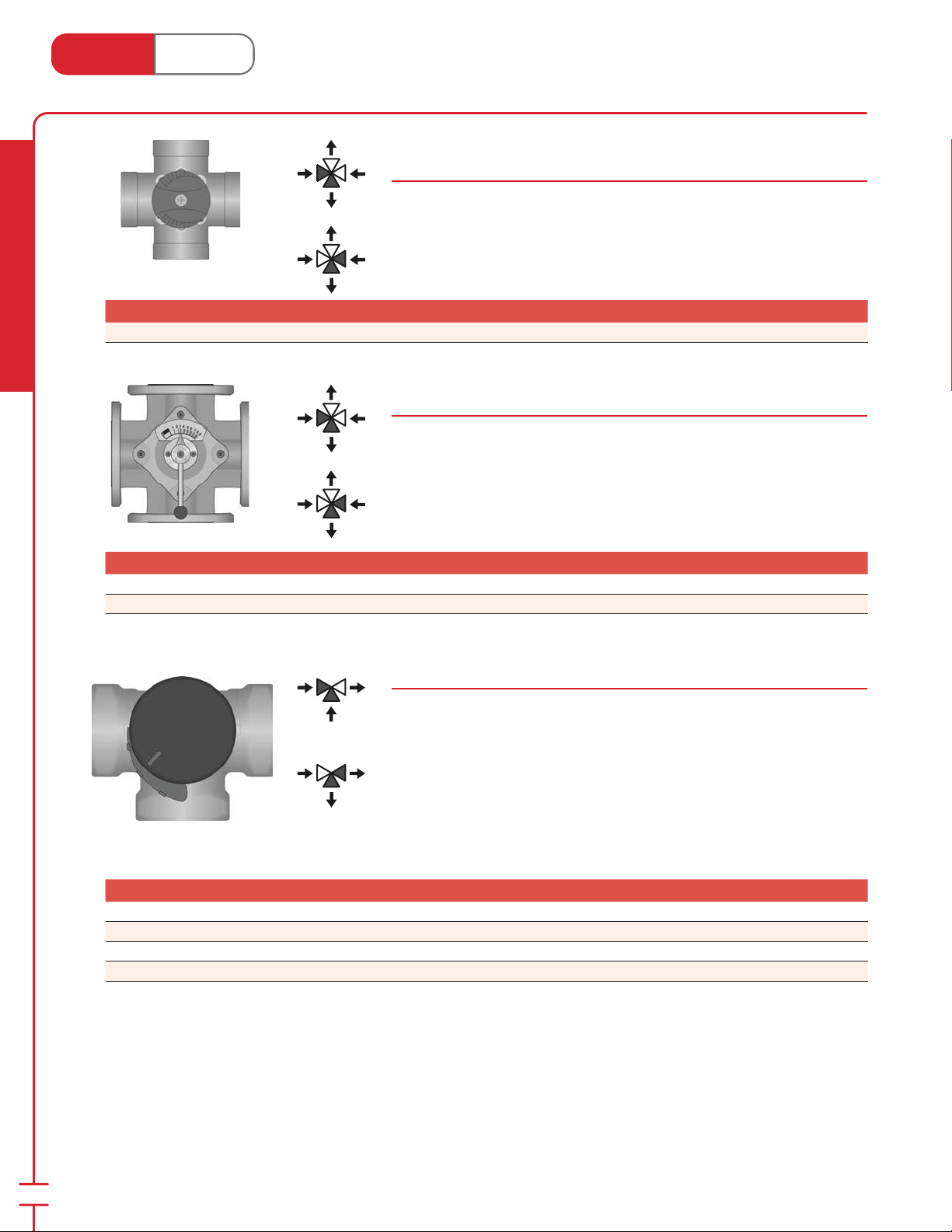
4-way FNPT Mixing Valves
64000 Series
This unit mixes high temperature boiler water with heating return water to create
a supply water temperature. It has the option of manual op er a tion, or it can be
tted with a Mixing Valve Motor for 1" and 1-1⁄4" Valves (#58130; page 35) for
fully automatic operation.
1-1⁄4" Cv = 17.4 (Kvs = 15)
Radiant Heating & Cooling
Stk# Description Pkg Qty Carton Qty Unit List Price / Unit
WSL
WSL
64165 2-1⁄2" × 4-way Flange Mixing Valve 1 ea.
64180 3" × 4-way Flange Mixing Valve 1 ea.
4-Way Flange Mixing Valves
64100 Series
This unit mixes high temperature boiler water with heating return water to
create a supply water temperature. It has the option of manual op er a tion, or it
can be tted with a mixing valve motor (#58199; page 35) for fully automatic
operation. Flanges are ANSI and DIN compatible.
2-1⁄2" Cv = 73.3 (Kvs = 63)
3" Cv = 116.3 (Kvs = 100)
3-way FNPT Mixing / Diverting Valves
63500 Series
This unit mixes high temperature boiler water with heating return water to create
a supply water temperature. It has the option of manual op er a tion, or it can be
tted with a Mixing Valve Motor for 1" to 2" FNPT Valves 3-Point Floating (#58131;
page 35) or Mixing Valve Motor for 1" to 2" FNPT Valves DDC (#58132; page
35) for fully automatic operation.
1" Cv = 11.7 (Kvs = 10)
1-
⁄4" Cv = 18.7 (Kvs = 16)
1-1⁄2" Cv = 29.3 (Kvs = 25)
2" Cv = 46.8 (Kvs = 40)
30
New!
New!
New!
New!
Stk# Description Pkg Qty Carton Qty Unit List Price / Unit
63026 1" × 3-way FNPT Mixing / Diverting Valve 1 ea.
63539 1-1⁄4" × 3-way FNPT Mixing / Diverting Valve 1 ea.
63541 1-1⁄2" × 3-way FNPT Mixing / Diverting Valve 1 ea.
63551 2" × 3-way FNPT Mixing / Diverting Valve 1 ea.
Page 33
Heat Link
1
3
1
3
1
www.heatlink.com
®
Mixing Valves
Canada - July 1, 2014
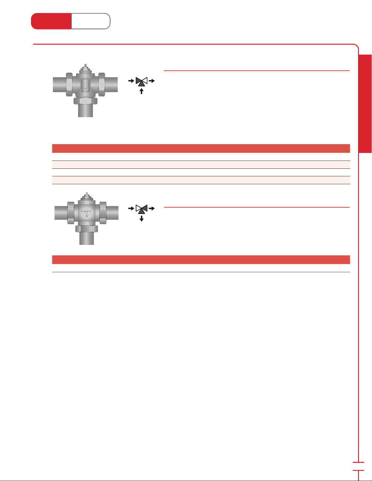
Compact 3-Way Mixing Valves
63700 Series
Three-way mixing valve for uid temperature control in heating and cooling
systems. Bronze valve body with brass nipples, protective cap, and stainless
spindle with double O-ring seal. Threads are compatible with actuators (#56201,
#56231, #56121; page 37) and thermostatic heads (#57091 and #57094; page
36).
⁄2" Cv = 2.9 (Kv = 2.5)
⁄4" Cv = 4.1 (Kv = 3.5)
1" Cv = 5.3 (Kv = 4.6)
1-1⁄4" Cv = 7.4 (Kv = 6.4)
Stk# Description Pkg Qty Carton Qty Unit List Price / Unit
63716
63720
63725 1" Compact 3-way Mixing Valve 1 ea.
63732 1-
⁄2" Compact 3-way Mixing Valve 1 ea.
⁄4" Compact 3-way Mixing Valve 1 ea.
⁄4" Compact 3-way Mixing Valve 1 ea.
1" 3-Way Diverter Valve
Stk# 63025
Provides on/o or modulated ow control with bypass for man i folds or
mis cel la ne ous sup ple men tal heating units. Fitted with three 1" sweat unions.
Threads are compatible with actuators (#56201, #56231, #56121; page 37) and
thermostatic heads (#57091 and #57094; page 36).
Cv = 6.0 (Kv = 5.12)
Radiant Heating & Cooling
WSL
Stk# Description Pkg Qty Carton Qty Unit List Price / Unit
63025 1" × 3-way Mixing/Diverting Valve 1 ea.
31
Page 34
Heat Link
1
3
1
3
3
3
www.heatlink.com
Stk# Description Pkg Qty Carton Qty Unit List Price / Unit
62325 Straight Balancing Valve 1" F/Sweat 1 24 ea.
Radiant Heating & Cooling
®
Valves
Canada - July 1, 2014
Straight Balancing Valve 1" Female Sweat
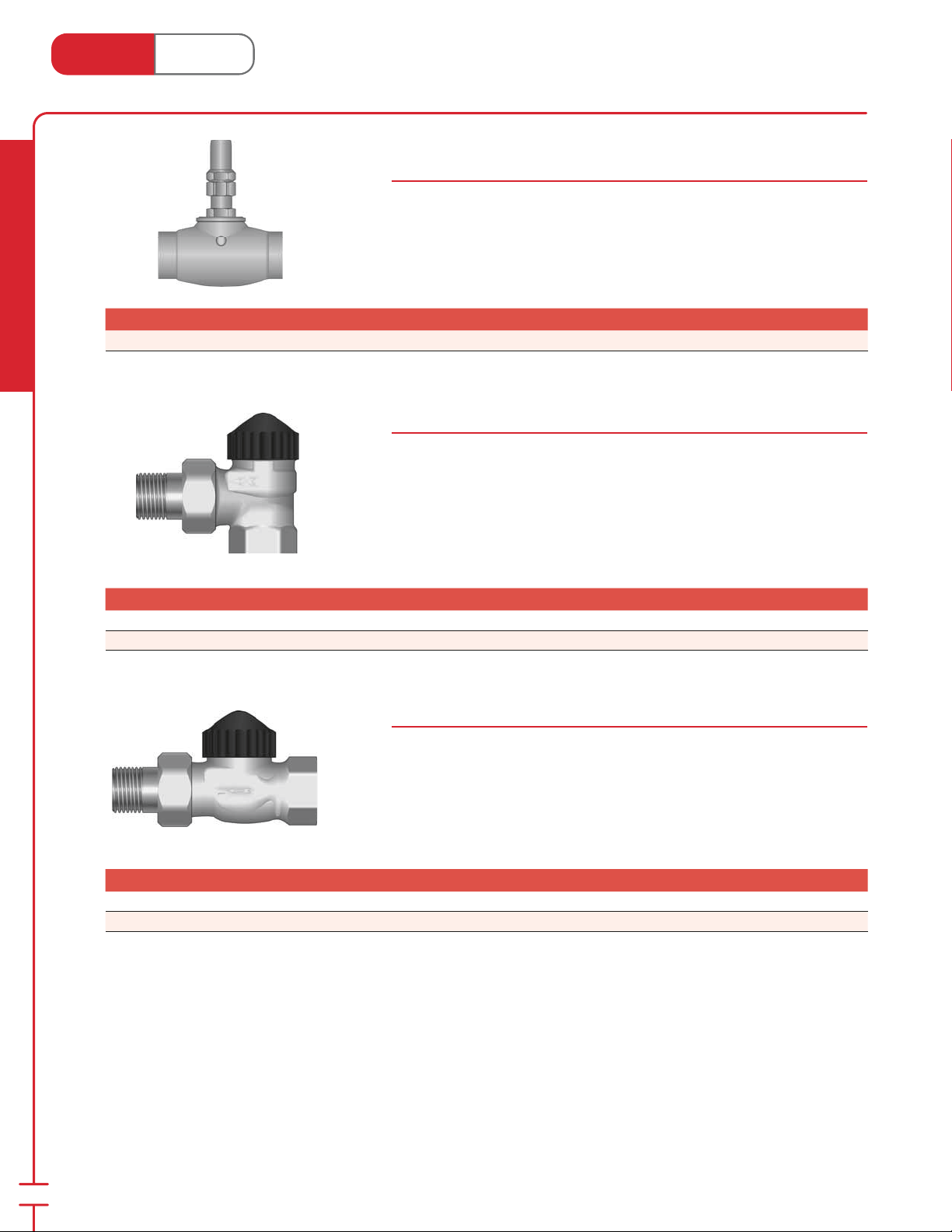
Stk# 62325
Flow balancing valve for use in injection systems and with the side stream lter.
90˚ Angle Radiator Valves
62100 Series
Provides on/o or modulated ow control for miscellaneous supplemental
heating units (e.g. towel warmers). Nickel plated. Threads are compatible with
actuators (#56201, #56231, #56121; page 37) and thermostatic heads (#57091
and #57094; page 36).
⁄2" Cv = 1.6 (Kv = 1.35)
⁄4" Cv = 2.9 (Kv = 2.5)
Stk# Description Pkg Qty Carton Qty Unit List Price / Unit
62116 90° Angle Radiator Valve 1⁄2", Nickel Plated 1 5 ea.
62120 90° Angle Radiator Valve
⁄4", Nickel Plated 1 20 ea.
Straight Radiator Valves
62200 Series
Provides on/o or modulated ow control for miscellaneous sup ple men tal
heating units (e.g. towel warmers). Nickel plated. Threads are compatible with
actuators (#56201, #56231, #56121; page 37) and thermostatic heads (#57091
and #57094; page 36).
⁄2" Cv = 1.6 (Kv = 1.35)
⁄4" Cv = 2.9 (Kv = 2.5)
Stk# Description Pkg Qty Carton Qty Unit List Price / Unit
62216 Straight Radiator Valve 1⁄2", Nickel Plated 1 20 ea.
62220 Straight Radiator Valve
⁄4", Nickel Plated 1 20 ea.
32
Page 35
Heat Link
1
1
1
3
3
1
www.heatlink.com
®
Valves
Canada - July 1, 2014
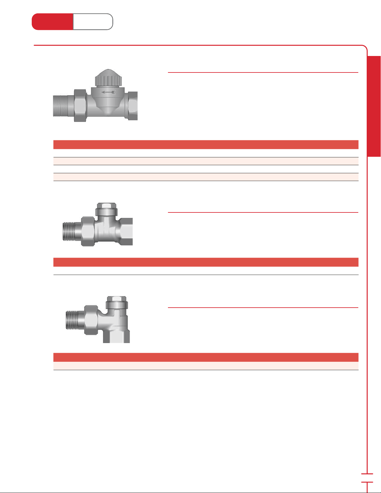
Straight Zone Valves/Injection Valves
62000 Series
Provides on/o or modulated ow control for baseboard, fan coils, manifolds,
and injection controls. Threads are compatible with actuators (#56201, #56231,
#56121; page 37) and thermostatic heads (#57091 and #57094; page 36).
⁄2" Cv = 2.9 (Kv = 2.5)
⁄4" Cv = 4.2 (Kv = 3.6)
1" Cv = 4.9 (Kv = 4.2)
1-1⁄4" Cv = 6.8 (Kv = 5.8)
Stk# Description Pkg Qty Carton Qty Unit List Price / Unit
62016 Straight Zone Valve 1⁄2" NPT 1 5 ea.
62020 Straight Zone Valve
62025 Straight Zone Valve 1" NPT 1 ea.
62030 Straight Zone Valve 1-
⁄4" NPT 1 5 ea.
⁄4" NPT 1 ea.
⁄2" Straight Return Connecter
Stk# 61016
Provides balancing for miscellaneous sup ple men tal heating units (e.g. towel
warmers). Gives a clean exposed nish when used with the HeatLink® zone valves
in supplemental heat applications. Nickel plated.
Cv = 1.6 (Kv = 1.35)
Radiant Heating & Cooling
Stk# Description Pkg Qty Carton Qty Unit List Price / Unit
61016 Straight Return Connecter 1⁄2" 1 20 ea.
⁄2" 90˚ Angle Return Connecter
Stk# 61116
Provides balancing for miscellaneous sup ple men tal heating units (e.g. towel
warmers). Gives a clean exposed nish when used with the HeatLink® zone valves
in supplemental heat applications. Nickel plated.
Cv = 1.6 (Kv = 1.35)
Stk# Description Pkg Qty Carton Qty Unit List Price / Unit
61116 90° Angle Return Connecter 1⁄2" 1 5 ea.
33
Page 36
Heat Link
3
1
www.heatlink.com
Radiant Heating & Cooling
Stk# Description Pkg Qty Carton Qty Unit List Price / Unit
60020 Pressure Activated Bypass Valve 3⁄4" 1 5 ea.
60025 Pressure Activated Bypass Valves 1" 1 5 ea.
60040 Pressure Activated Bypass Valves 1-
®
Valves
Canada - July 1, 2014
Pressure Activated Bypass Valve
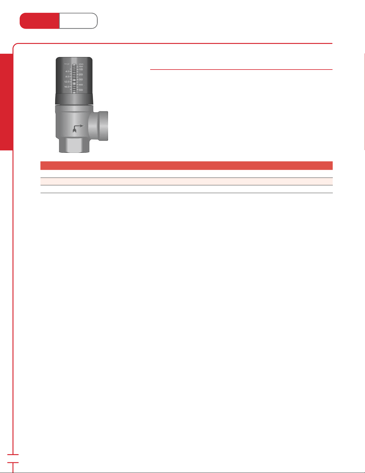
60000 Series
This valve prevents a steep rise of the pump head and maintains ow at a stable
rate. Also ensures only required amount of cir cu lat ing water is used for hydronic
systems. The 3⁄4" valve can be ad just ed to any point between 1.5 and 17 ft H2O (50
and 500 mbar). The 1" and 1-1⁄4" can be adjusted to any point between 10 and 60 ft
H2O (30 and 1800 mbar).
⁄4" max. ow = 13 US gpm (2950 L/h)
1" max. ow = 22 US gpm (5000 L/h)
1-1⁄4" max. ow = 35 US gpm (7950 L/h)
⁄4" 1 5 ea.
34
Page 37
Heat Link
www.heatlink.com
®
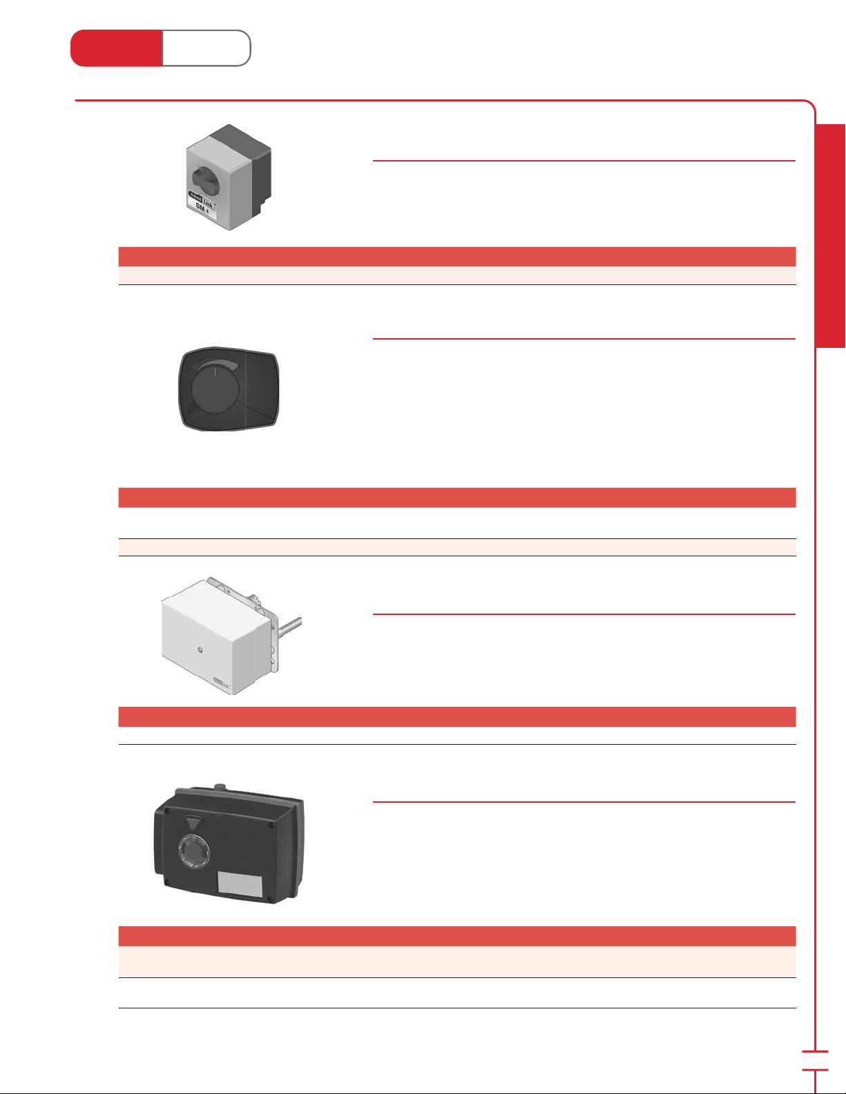
Mixing Valve Motors
Canada - July 1, 2014
WSL
New!
New!
Mixing Valve Motor for 1" & 1-1⁄4" Valves
Stk# 58130
Used to automatically operate the 4-way mixing valve. The motor is reversible
and is provided with xed limit switches. For use with 1-1⁄4" mixing valves (#64030;
page 30).
24 Vac 50/60 Hz 2 VA
Stk# Description Pkg Qty Carton Qty Unit List Price / Unit
58130 Mixing Valve Motor for 1" and 1-1⁄4" Valves 1 ea.
Mixing Valve Motors for 1" to 2" Rotary NPT Valves
Stk# 58131 & 58132
Used to automatically operate the 4-way or 3-way mixing valve. For use with
4-way FNPT mixing valves (#64026, #64031, #64041, #64051; page 29) and
3-way FNPT mixing / diverting valves (#63026, #63539, #63541, #63551; page
30.
#58131 motor is oating 3-point action mixing valve motor.
24 Vac 50/60 Hz 2 VA
#58132 motor is DDC mixing valve motor.
24 Vac/dc 50/60 Hz 4 VA
Stk# Description Pkg Qty Carton Qty Unit List Price / Unit
58131
58132 Mixing Valve Motor for 1" to 2" FNPT Valves DDC 1 ea.
Mixing Valve Motor for 1" to 2" FNPT Valves 3-Point
Floating
1 ea.
Radiant Heating & Cooling
WSL
New!
New!
Mixing Valve Motors for 2-1⁄2" to 4" Flange Mixing Valves
Stk# 58199
Used to automatically operate the 4-way ange mixing valve. The motor is
re vers ible and is provided with xed limit switches. For use with anged 2-1⁄2" and
3" mixing valves (#64165 and #64180; page 30).
24 Vac 50/60 Hz 2 VA
Stk# Description Pkg Qty Carton Qty Unit List Price / Unit
58199 Mixing Valve Motor for 2-1⁄2" to 4" Flange Mixing Valves 1 ea.
Mixing Valve Motors for 2" to 4" Flange Mixing Valves
Stk# 58200 & 58300
Used to automatically operate the 4-way ange mixing valve. For use with anged
2" to 4" mixing valves (#64164, #64166, #64181, #65000; page 29).
#58200 motor is oating 3-point action mixing valve motor.
24 Vac 50/60 Hz 2 VA
#58300 motor is DDC mixing valve motor.
24 Vac/dc 50/60 Hz 5 VA
Stk# Description Pkg Qty Carton Qty Unit List Price / Unit
58200
58300
Mixing Valve Motor for 2" to 4" Flange Mixing Valves
3-Point Floating
Mixing Valve Motor for 2" to 4" Flange Mixing Valves
DDC
1 ea.
1 ea.
35
Page 38
Heat Link
www.heatlink.com
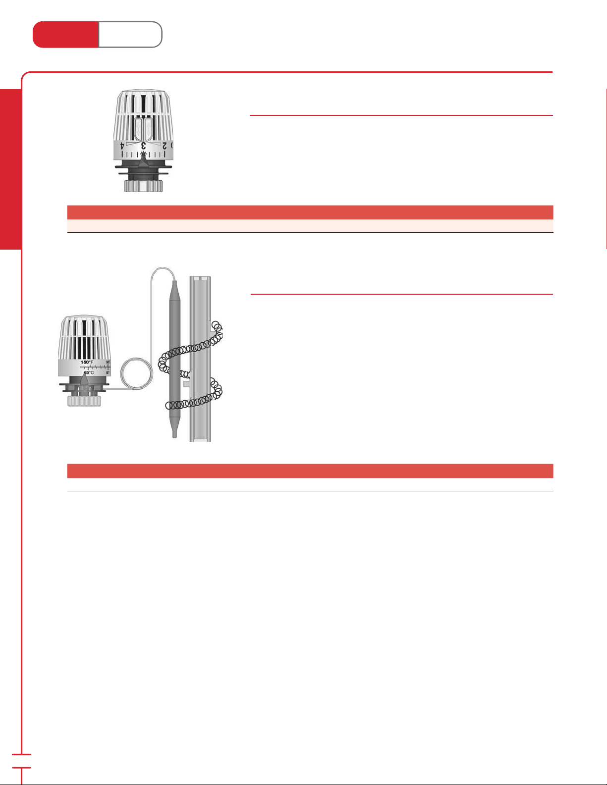
Stk# Description Pkg Qty Carton Qty Unit List Price / Unit
57091 Thermostatic Head (16°-28°C) 1 ea.
Radiant Heating & Cooling
®
Thermostatic Heads
Canada - July 1, 2014
Thermostatic Head
Stk# 57091
Thermostatic head for HeatLink® zone valves. Maximum setting 84˚F (29˚C).
Senses 0.4˚F (0.2˚C) air temperature change. Takes 24 minutes to close from full
open.
Thermostatic Head with 6' (1.8 m) Remote Cap il lary
Stk# 57094
Used as injection control for HeatLink® zone valves. Senses 0.4˚F (0.2˚C) supply
water change. Takes 15 minutes to close from full open.
Temperature adjustment range: 96-150°F (36-66°C)
Stk# Description Pkg Qty Carton Qty Unit List Price / Unit
57094 Thermostatic Head c/w Capillary (86°-149°F) 1 ea.
36
Page 39
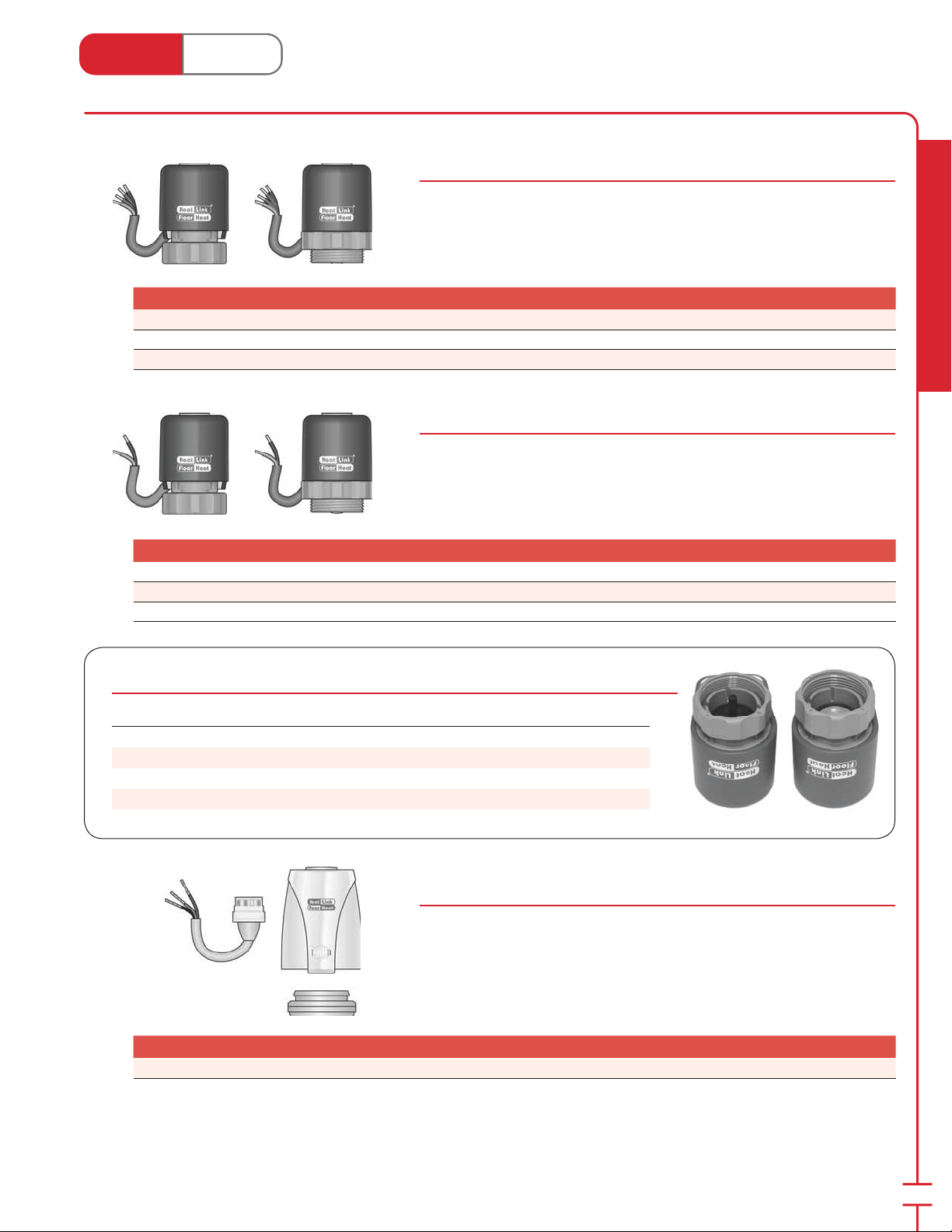
Heat Link
www.heatlink.com
®
Actuators
Canada - July 1, 2014
5623256230/1
Actuators c/w End Switch
56230 Series
These motors allow for additional room temperature control in con junc tion with
a room thermostat by mounting on a TwistSeal® supply man i fold module (56230),
Stainless Steel Manifold (56231), HeatLink® 62000 & 63000 series zone valves
(56231), or TwistSeal® Multiport Manifold (56232). Comes complete with end
switch to allow pump and/or boiler switching.
Stk# Description Pkg Qty Carton Qty Unit List Price / Unit
56230 HeatLink® TwistSeal® Manifold Actuator c/w End Switch 1 100 ea.
56231 HeatLink® Valve & SS Manifold Actuator c/w End Switch 1 100 ea.
56232 HeatLink® Multiport Manifold Actuator c/w End Switch 1 100 ea.
5620256200/1
Actuators
56200 Series
These actuators allow for additional room temperature control in con junc tion
with a room thermostat by mounting on a TwistSeal® supply man i fold module
(56200), Stainless Steel Manifold (56201), HeatLink® 62000 & 63000 series zone
valves (56201), or TwistSeal® Multiport Manifold (56202). Includes a heat demand
LED indicator.
Stk# Description Pkg Qty Carton Qty Unit List Price / Unit
56200 HeatLink® TwistSeal® Manifold Actuator with LED 1 100 ea.
56201 HeatLink® Valve & SS Manifold Actuator with LED 1 100 ea.
56202 HeatLink® Multiport Manifold Actuator with LED 1 100 ea.
Radiant Heating & Cooling
How to tell the 562x0 and 562x1 actuators apart
Actuator LED End Switch Female Thread Center Pin Mounts on
56200 Yes No Fine Yes TwistSeal® 78200 & 78400
56201 Yes No Coarse No Valves & SS manifolds
56230 No Yes Fine Yes TwistSeal® 78200 & 78400
56231 No Yes Coarse No Valves & SS manifolds
DDC Actuator
Stk# 56121
These actuators allow for additional room temperature control when used in
conjunction with a direct digital control system by mounting on a Stainless Steel
Manifold, or HeatLink® 62000 & 63000 series zone valves.
Stk# Description Pkg Qty Carton Qty Unit List Price / Unit
56121 HeatLink® DDC Actuator for Manifolds and Valves 1 100 ea.
56201 / 5623156200 / 56230
37
Page 40
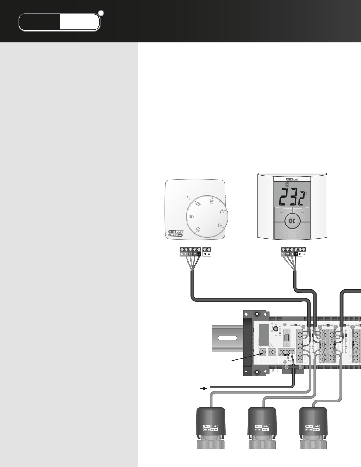
®
LinkStat
Electronic Control System
HeatLink did some simple addition, and
came up with a signi cant innovation.
By adding an LED on our new StatLink®
zone drive actuator, HeatLink has reduced
the waiting time. The LED immediately
indicates heat demand. Along with our
new thermostats and zone modules, the
result is a completely visual feedback
system. To sum it up, it’s situation
normal…at-a-glance.
We’ve also gone color-coded and
digital. Of the ve thermostats StatLink®
now o ers, one is mechanical, one is
electronic, and three are digital. The
manual or automatic setback on the
electronic and digital thermostats,
provide energy savings by lowering the
temperature of unoccupied rooms.
Electronic Thermostat
#46443
• analog electronic
regulation
• heat demand LED
• large, easy to adjust dial
• 3 position operation
selector switch: heat,
manual or automatic
(external timer) setback
• setback of 4˚C (7˚F)
• 3 or 4 wire operation
• internal or external sensor
operation
Digital Thermostat
#46544
• proportional integral
temperature regulation
• fully menu driven
• large digital display
• manual or automatic (external
timer) setback
• adjustable setback temperature
• room, oor or combined sensor
operation
• adjustable characteristics for
system optimization (high mass,
low mass, baseboard, fan coil and
cooling)
All thermostats are designed for use
with standard AWG 18 cable. Our screw
terminals are color-coded to match the
wire colors found in re-alarm cable
(FAS105).
Our StatLink® modules simplify the
whole wiring process, and eliminate that
tangled mess of wires. The color-coded
screw terminals indicate where each wire
goes in the heating zones. Each zone
has an LED indicator for heat demand,
and up to 4 actuators can be connected
to each zone. It also acts as a combined
end-switch for all zones, by activating the
boiler and pump when heat is required.
HeatLink’s new StatLink® system saves
the contractor both time and money, by
focusing on ease of installation and ease
of use. The new StatLink® is a welcome
addition to the HeatLink family, and our
customers will nd it is an excellent t
with our other product lines.
Dual Dry Contacts
external
sensor
24Vac Power
Page 41
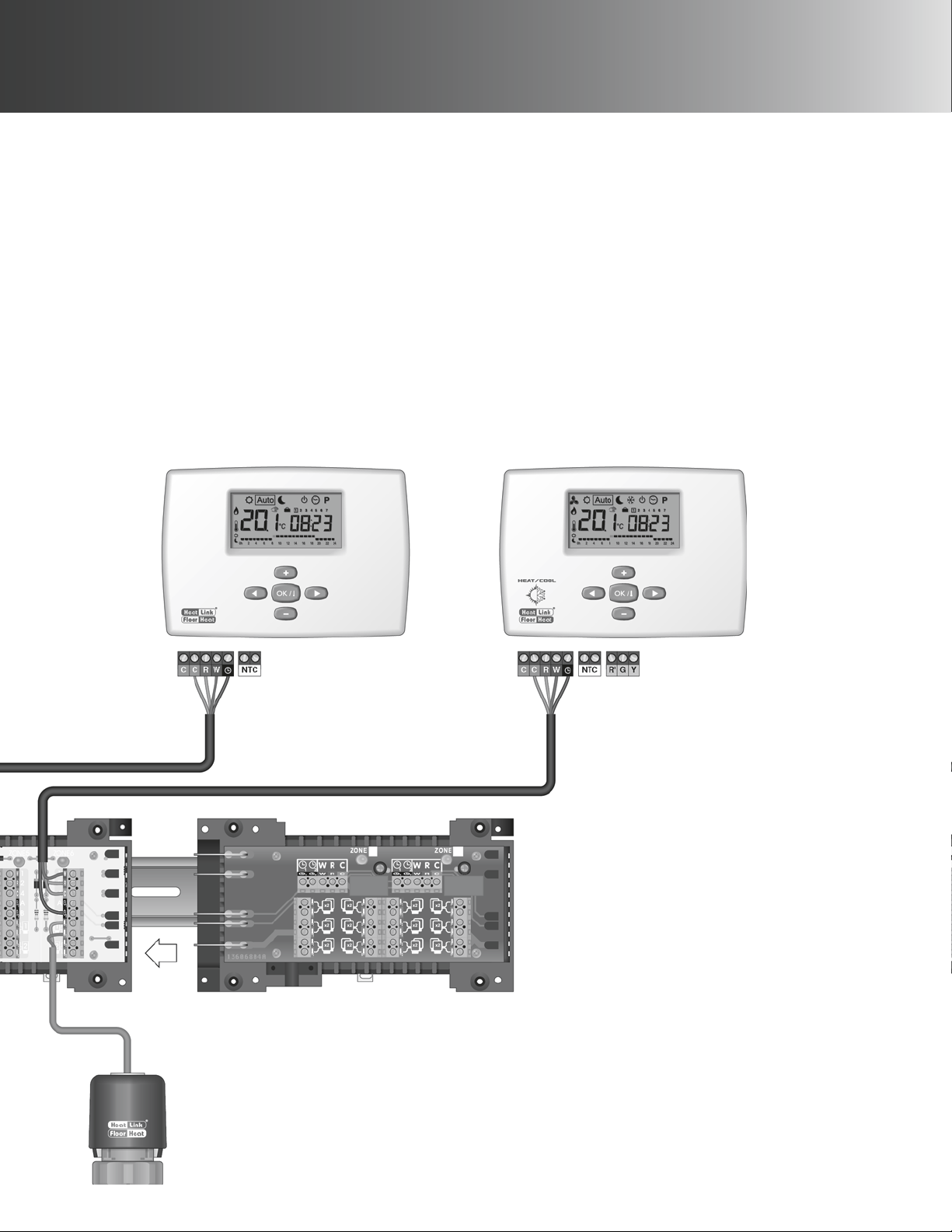
Digital Timer Thermostat
#46643
• proportional integral temperature
regulation
• fully menu driven
• large digital display
• easy to program 7 day 24 hour timer with 4
user programs and 9 xed programs
• room, oor or combined sensor operation
• setback signal feedback to StatLink
• ITCS function for intelligent setback
functionality
• adjustable characteristics for system
optimization (high mass, low mass,
baseboard, fan coil and cooling)
®
Digital Heat/Cool Timer Thermostat
#46673
• proportional integral temperature regulation
• fully menu driven
• large digital display
• easy to program 7 day 24 hour timer with 4
user programs and 9 xed programs
• room, oor or combined sensor operation
• setback signal feedback to StatLink
• ITCS function for intelligent setback
functionality
• adjustable characteristics for system
optimization (high mass, low mass,
baseboard, fan coil and cooling)
• heat, cool, fan, or automatic operation
®
Actuators
#56200 Series
• heat demand LED indicator
• available with endswitch
cooling
contacts
StatLink® 6 Zone Base Module - #40226
• 24Vac input
• boiler and pump switching via dual dry contacts
• heat demand LEDs for each zone
• up to 4 actuators per zone
• max. 12 actuators with the addition of a 60VA
transformer
StatLink® 4 Zone Expansion Module - #40234
(not shown)
• easy addition of 4 zones
• heat demand LEDs for each zone
• up to 4 actuators per zone
StatLink® 2 Zone Heavy Duty Expansion
Module - #40242
• easy addition of 2 zones
• heat demand LEDs for each zone
• up to 12 actuators per zone
Page 42
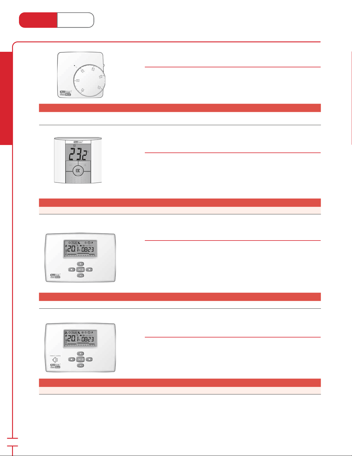
Heat Link
www.heatlink.com
Stk# Description Pkg Qty Carton Qty Unit List Price / Unit
46443
HeatLink® Electronic Thermostat with LED and Setback
®
Thermostats
Canada - July 1, 2014
Electronic Thermostat
Stk# 46443
Provides analog electronic temperature regulation. Screw terminal connection
for use with standard thermostat wire. 3 position operation selector switch:
heat, manual or automatic (external timer) setback. Includes heat demand LED.
Optional external sensor.
Selector Switch
1 ea.
Radiant Heating & Cooling
Stk# Description Pkg Qty Carton Qty Unit List Price / Unit
46544 HeatLink® Digital Thermostat "new design" 1 ea.
Stk# Description Pkg Qty Carton Qty Unit List Price / Unit
46643 HeatLink® Digital Timer Thermostat 1 ea.
Digital Thermostat
Stk# 46544
Provides proportional integral temperature regulation. Screw terminal connection
for use with standard thermostat wire. Adjustable manual or automatic (external
timer) setback. Features a fully menu driven large backlit digital display. O ers
optimization for various system types (high mass, low mass, baseboard, fan coil
and cooling). Optional external sensor.
Digital Timer Thermostat
Stk# 46643
Provides proportional integral temperature regulation for maximum comfort and
e ciency. Features a fully menu driven large digital display. O ers optimization
for various system types (high mass, low mass, baseboard, fan coil and cooling).
Take control with the easy to program 7 day 24 hour timer utilizing 9 preset
programs and the ability to program 4 additional user programs. This thermostat
is capable of generating a setback signal that can be best utilized with a StatLink®
module and shared with other thermostats. Optional external sensor.
40
Digital Heat/Cool Timer Thermostat
Stk# 46673
Provides all the functionality of the Digital Timer Thermostat (#46643) plus
cooling and fan control. Operational modes consist of: heat, cool, fan, or
automatic. Optional external sensor.
Stk# Description Pkg Qty Carton Qty Unit List Price / Unit
46673 HeatLink® Digital Heat/Cool Timer Thermostat 1 ea.
Page 43
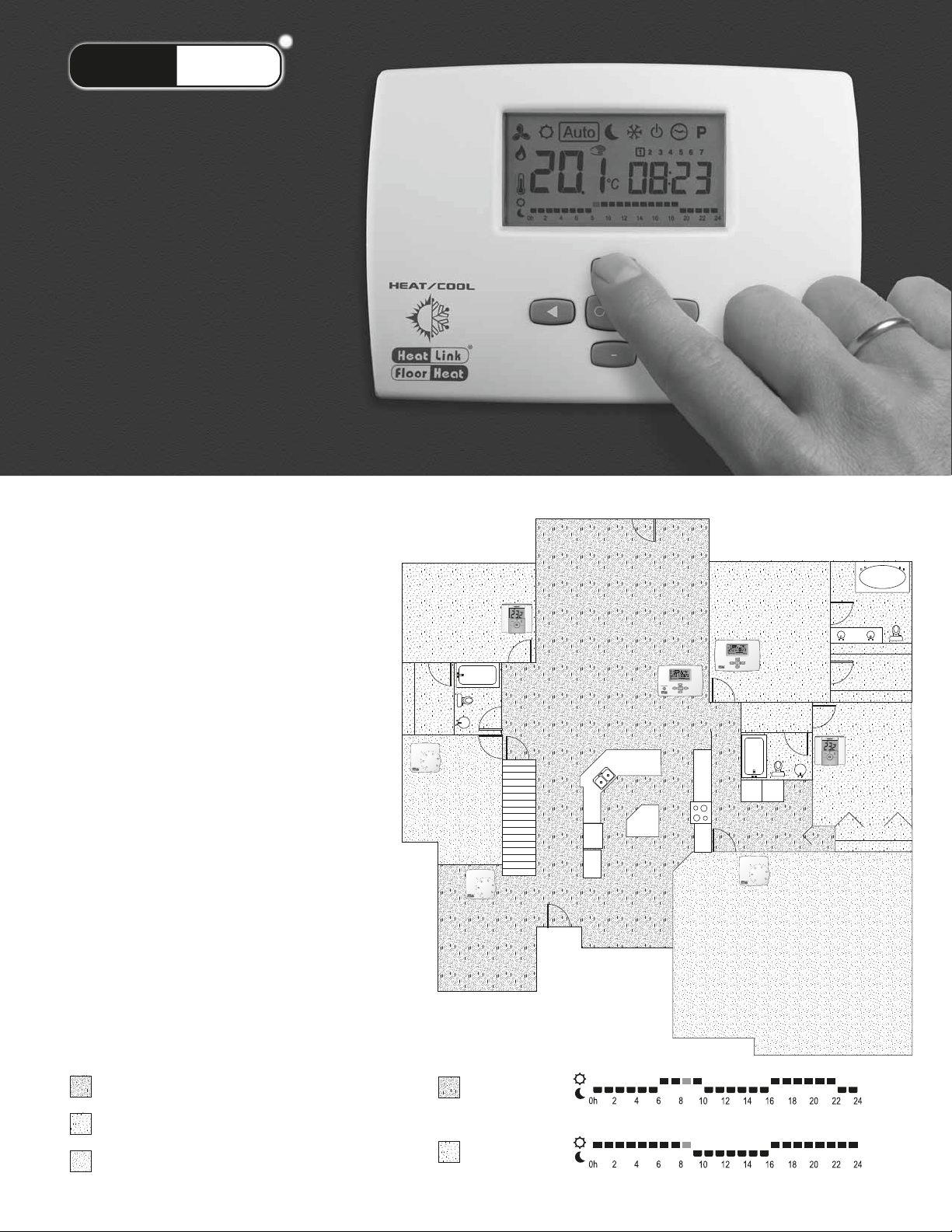
®
LinkStat
You’re in Control
… because every
family has
di erent needs,
and every home
is unique.
A traditional forced air system with one
central thermostat may need to be set
higher than necessary to ensure that some
parts of the house get su cient heat.
®
With HeatLink
a house can be divided into di erent
heating zones. Each zone will have it’s own
thermostat that will set it’s temperature
independently from the other zones. This
means that you can heat only the rooms
that need heat. Rooms that don’t need
to be heated can be put into “setback,” a
lower user adjustable temperature, to save
energy.
Add a timer thermostat to automatically
switch between normal operation and
setback operation on a set schedule. This
schedule will let you automatically lower
the temperature of your home when no
one’s home and bring the temperature
back up to greet you upon your return.
radiant oor heating,
Bedroom #2
Den
Dining Room
Master Bedroom
Living Room
Kitchen
Garage
Example:
Living area is heated in the morning and evening,
and setback during the day and at night.
Bedrooms are heated during the night, and setback
during the day.
Less frequently used rooms can be manually
switched to and from setback mode.
Setback Channel 1 - Living Area
Normal operation
Setback operation
Setback Channel 2 - Bedrooms
Normal operation
Setback operation
24 hour schedule
Page 44
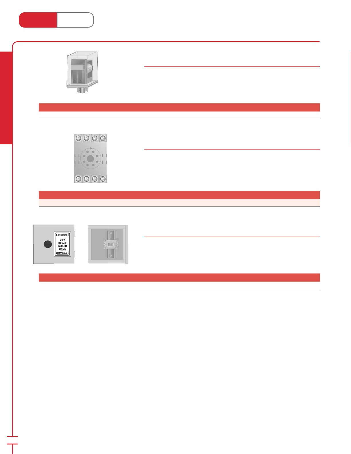
Heat Link
www.heatlink.com
Stk# Description Pkg Qty Carton Qty Unit List Price / Unit
45012 24Vac DPDT Pump Relay 1 ea.
®
24V AC Relay
Canada - July 1, 2014
24Vac DPDT Pump Relay
Stk# 45012
Double pole double throw relay used for pump and/or boiler control. Use with
socket #45032 sold separately.
Contacts: 10A resistive, 7.5A inductive @ 110 Vac, 1⁄4 hp.
7.5A resistive, 5.0A inductive @ 220 Vac, 1⁄3 hp.
Radiant Heating & Cooling
Stk# Description Pkg Qty Carton Qty Unit List Price / Unit
45032 8 Pin Round Socket for AC Relay 1 ea.
Stk# Description Pkg Qty Carton Qty Unit List Price / Unit
45112 HeatLink® 24Vac DPDT Pump Relay Box 1 ea.
24Vac DPDT Pump Relay Socket
Stk# 45032
Socket for 24V AC DPDT pump relay #45012. Easily mounted on DIN rail.
24Vac DPDT Pump Relay Box
Stk# 45112
Electrical enclosure complete with #45012 relay, #45032 socket, and DIN rail.
Contacts: 10A resistive, 7.5A inductive @ 110 Vac, 1⁄4 hp.
7.5A resistive, 5.0A inductive @ 220 Vac, 1⁄3 hp.
42
Page 45
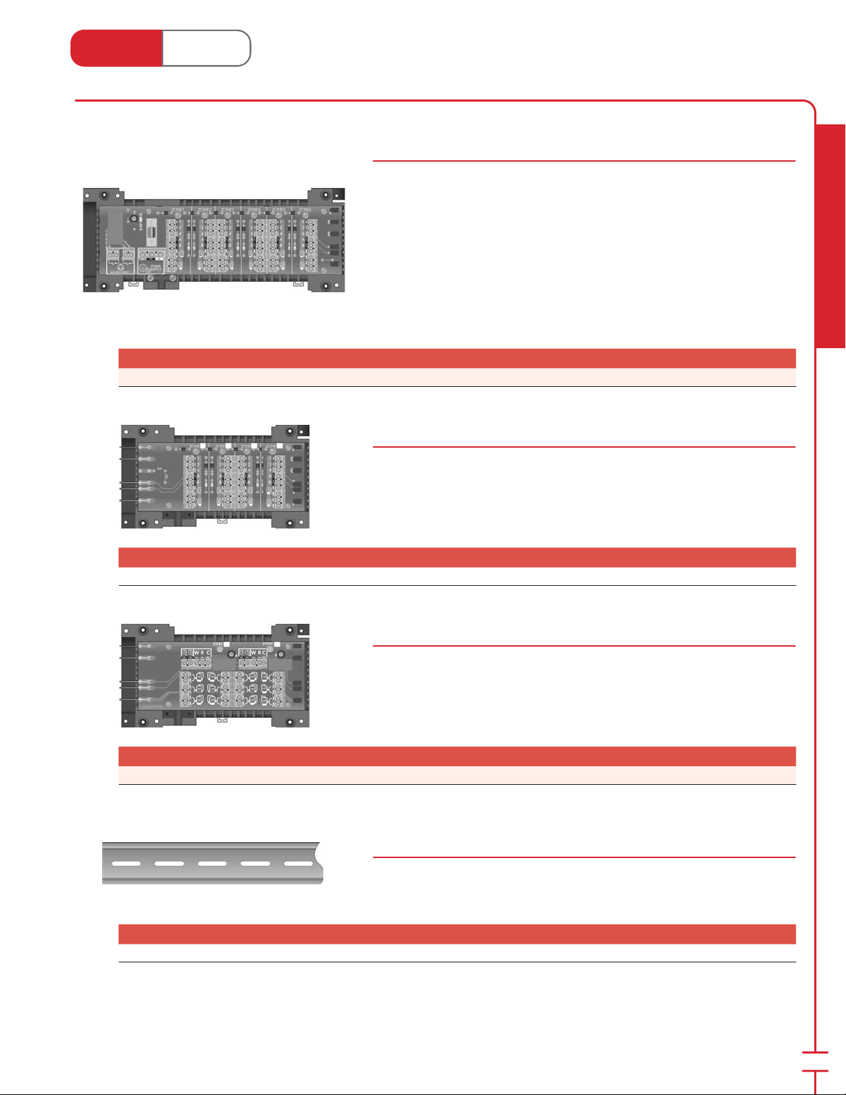
Heat Link
www.heatlink.com
®
StatLink® Modules
Canada - July 1, 2014
StatLink® 6 Zone Base Module
Stk# 40226
The StatLink® 6 zone base module is complete with all the main electrical
connections for a hydronic oor heating system. This module can be mounted
either on a DIN rail or directly to a wall. It connects room thermostats to their
corresponding actuators. Each zone has an LED which indicates if it is calling for
heat. A timer thermostat (#46643 or #46673) can send a setback signal to other
thermostats via terminal Clock 1 or 2. As soon as there is a heat demand from one
zone, a relay with two dry contacts is switched on (Pump, Boiler …). Add more
zones by plugging in the #40234 or #40242 module.
The 6 zone base module has a current rating of 2.5A; a 60VA transformer allows
for 20 actuators per base module to be connected with up to 4 actuators per
zone.
Stk# Description Pkg Qty Carton Qty Unit List Price / Unit
40226 StatLink® 6 Zone Base Module 1 ea.
StatLink® 4 Zone Expansion Module
Stk# 40234
The StatLink® 4 zone expansion module connects to the StatLink® 6 zone base
module, allowing 4 more room thermostats to connect to their corresponding
actuators. The 4 zone expansion module has a current rating of 2.5A.
Radiant Heating & Cooling
Stk# Description Pkg Qty Carton Qty Unit List Price / Unit
40234 StatLink® 4 Zone Expansion Module 1 ea.
StatLink® 2 Zone Heavy Duty Expansion Module
Stk# 40242
The StatLink® 2 zone heavy duty expansion module connects to the StatLink®
6 zone base module or power module, allowing 2 more room thermostats to
connect to up to 12 actuators each. Note: max. 60 VA transformer allows for up
to 20 actuators. The 2 zone heavy duty expansion module has a current rating of
2.5A.
Stk# Description Pkg Qty Carton Qty Unit List Price / Unit
40242 StatLink® 2 HD Zone Expansion Module 1 ea.
Installation Track for StatLink® Modules
Stk# 44325
Allows for easy and fast installation of all control modules.
Length = 25"
Stk# Description Pkg Qty Carton Qty Unit List Price / Unit
44325 StatLink® Installation Track, 25" 1 ea.
43
Page 46
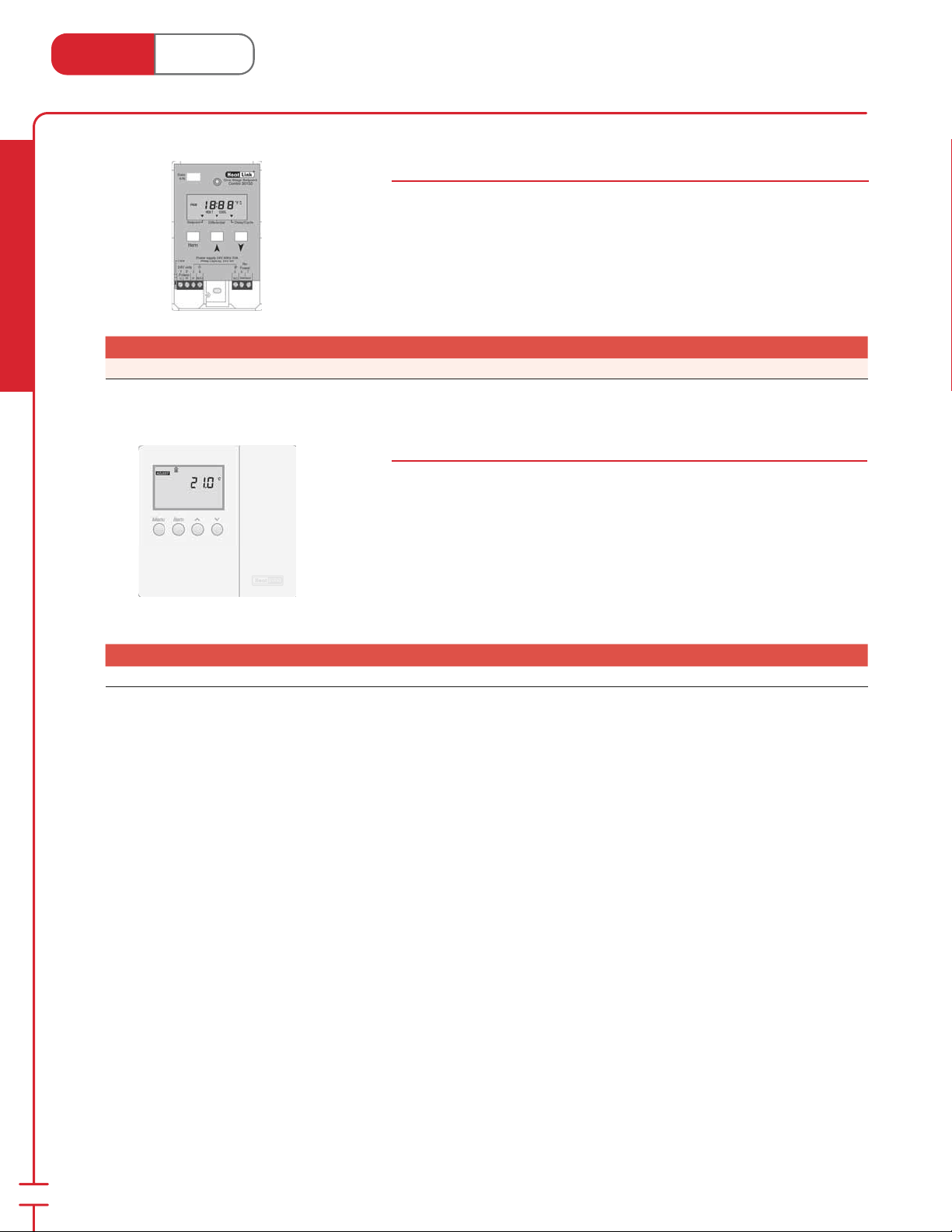
Heat Link
www.heatlink.com
Stk# Description Pkg Qty Carton Qty Unit List Price / Unit
Radiant Heating & Cooling
30150 One Stage Setpoint Control 1 ea.
®
Controls
Canada - July 1, 2014
HeatLink® One Stage Setpoint Control
Stk# 30150
One stage SPDT heating and cooling setpoint control. Pulse width modulation
or bang-bang operation. Features adjustable di erential and adjustable delay or
cycle.
1 universal sensor is included.
24 Vac 50/60 Hz 1 VA
HeatLink® Compact Mixing Reset Control
Stk# 31355
The 31355 Compact Mixing Reset Control regulates the supply water temperature
of an automated mixing valve in order to provide outdoor reset or setpoint
operation. The 31355 provides a oating action (3-way or 4-way mixing) or a
0/2–10 Vdc (2-way injection) signal to adjust the mixing valve position. The 31355
also includes two separate night setback channels.
Outdoor sensor and 1 universal sensor are included.
24Vac 50/60 Hz 50 VA (max)
Stk# Description Pkg Qty Carton Qty Unit List Price / Unit
31355 HeatLink® Compact Mixing Reset Control 1 ea.
44
Page 47
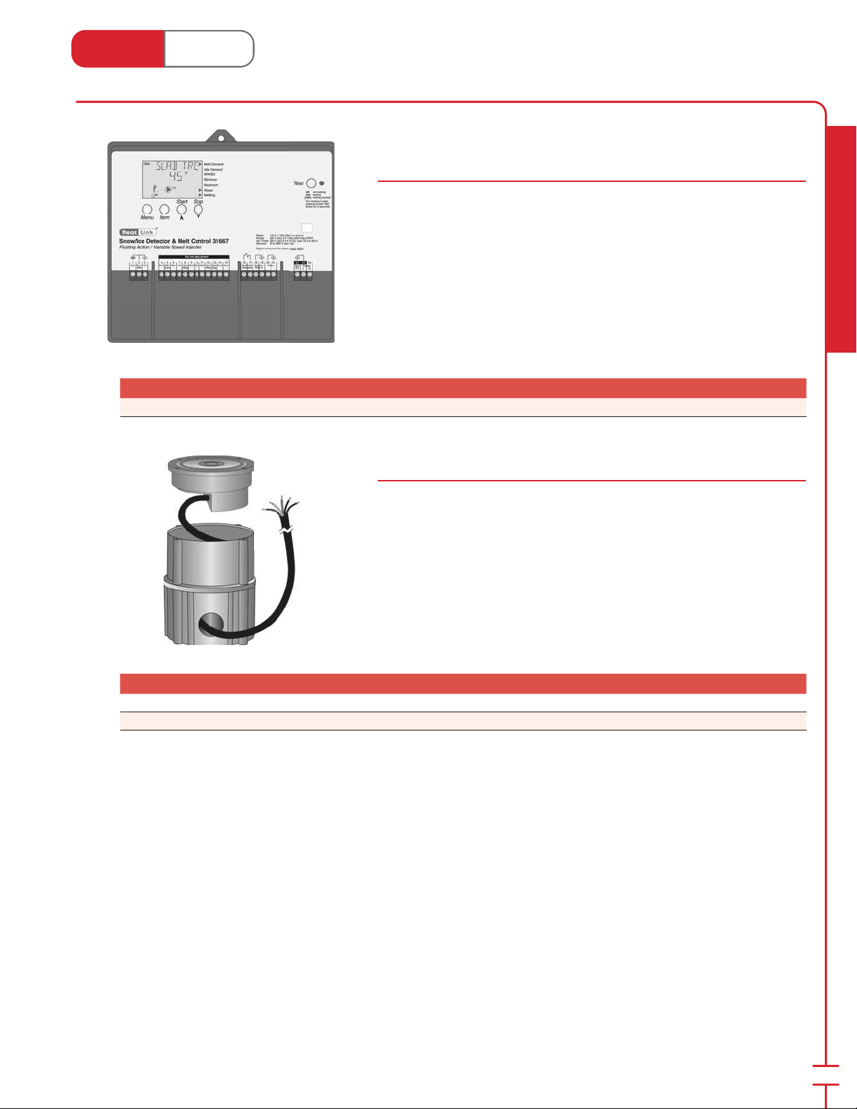
Heat Link
www.heatlink.com
®
Controls
Canada - July 1, 2014
HeatLink® Snow/Ice Detector & Melting Control - Floating Action
/ Variable Speed
Stk# 31667
The 31667 Snow/Ice Detector & Melting Control is designed to control a single
zone snow melting system. The snow melting system may be started manually
or automatically through the use of a Snow/Ice Sensor (#30090). The control
automatically adjusts the mixed supply water to the snow melting system by
controlling a variable speed pump or oating action mixing valve. The 31667
control includes a large Liquid Crystal Display (LCD) in order to view system status
and operating information.
Outdoor sensor and 2 universal sensors are included.
120 Vac 50/60 Hz 600 VA
Stk# Description Pkg Qty Carton Qty Unit List Price / Unit
31667 HeatLink® Snow/Ice Detector & Melt Control 1 ea.
Snow/Ice Detector (Sensor)
Stk# 30090, 30091
This snow/ice sensor in conjunction with the 31667, ac ti vates and con trols a snow
melting system based on moisture (snow/ice) and slab tem per a ture. This control
is not designed as a simple de tec tion device and will not operate properly in an
un heat ed slab.
Radiant Heating & Cooling
Stk# Description Pkg Qty Carton Qty Unit List Price / Unit
30090 Snow/Ice Sensor (10K) 65 ft cable 1 ea.
30091 Snow/Ice Sensor Socket 1 ea.
45
Page 48
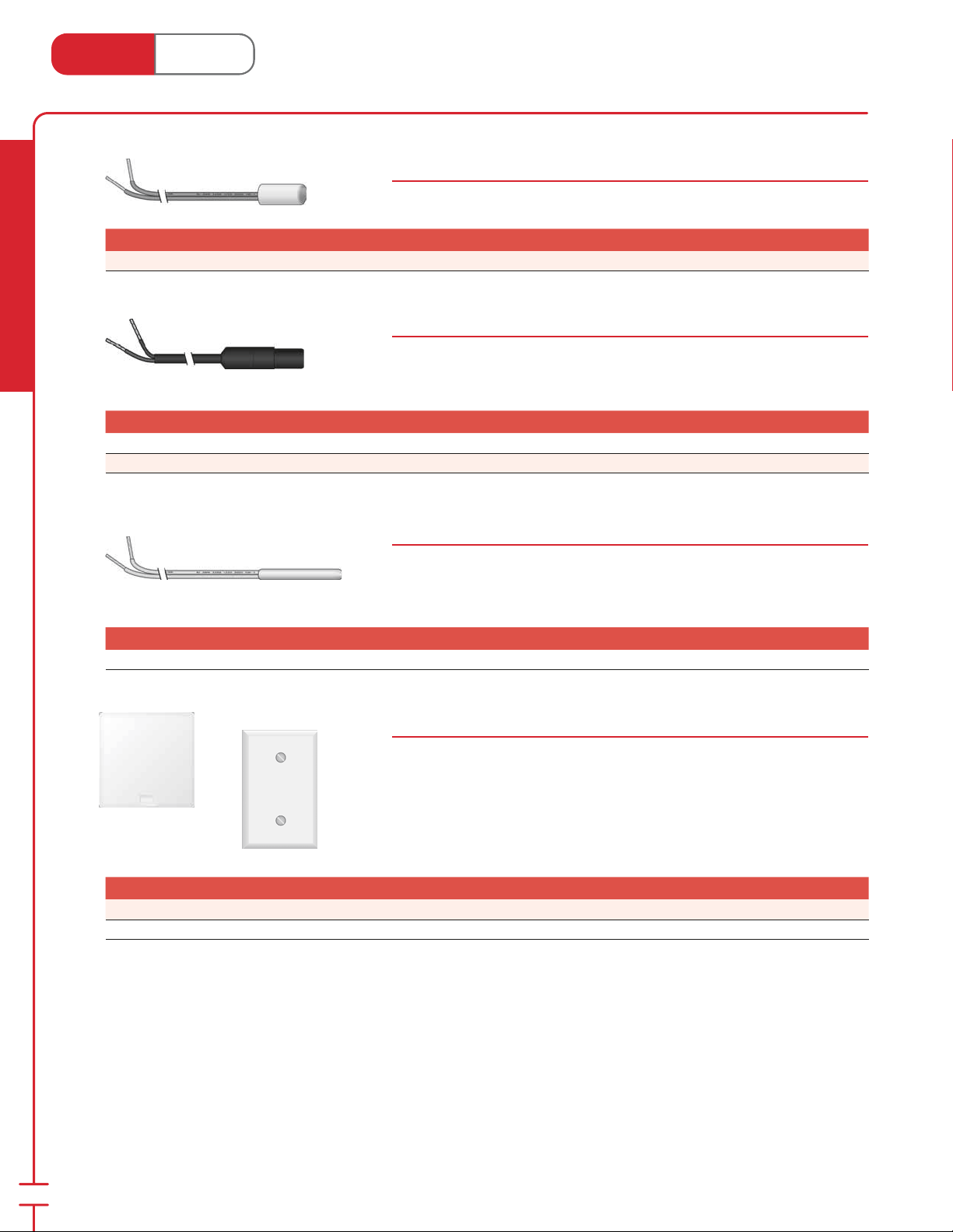
Heat Link
www.heatlink.com
Stk# Description Pkg Qty Carton Qty Unit List Price / Unit
30071 Universal Sensor (10K) 1 10 ea.
Radiant Heating & Cooling
Stk# Description Pkg Qty Carton Qty Unit List Price / Unit
30072 Slab Sensor (10K) PVC Sleeve 20ft Cable 1 ea.
30073 Slab Sensor (10K) PVC Sleeve 40ft Cable 1 ea.
®
Sensors
Canada - July 1, 2014
Universal Sensor
Stk# 30071
Standard sensor for use as optional sensor in 30000 series controls.
Slab Sensor - PVC Sleeve
Stk# 30072, 30073
Sensors for use in measuring slab or ground temperatures. The 30072 and 30073
standard sensors with PVC sleeve are designed for use in soil or concrete. For use
with 30000 series controls and 46000 series thermostats.
Slab Sensor - Stainless Steel Sleeve
Stk# 30079
Sensors for use in measuring slab or ground temperatures. The 30079 sensor with
stainless steel sleeve is designed for use in concrete, thin-set and grout. For use
with 30000 series controls and 46000 series thermostats.
Stk# Description Pkg Qty Carton Qty Unit List Price / Unit
30079 Slab Sensor (10K) SS Sleeve 10ft Cable 1 ea.
Indoor Sensors
Stk# 30076, 30077
These 10k sensors provide accurate measurement of the indoor air tem per a ture.
The 30076 sensor can be mounted directly on the wall using two #6 - 1" screws.
The 30077 sensor can be mounted ush onto a stan dard duplex electrical box. For
use with 30000 series controls.
Stk# Description Pkg Qty Carton Qty Unit List Price / Unit
30076 Indoor Sensor (10K) Small Enclosure 1 ea.
30077 Indoor Sensor (10K) Flush Mount 1 ea.
46
Page 49
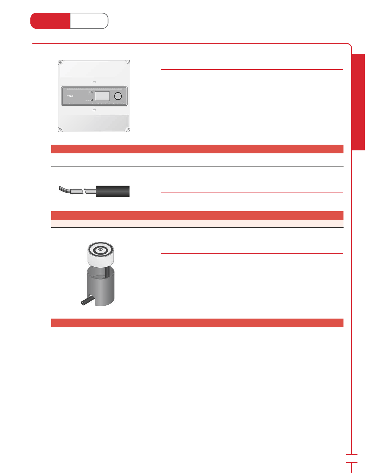
Heat Link
www.heatlink.com
®
Controls
Canada - July 1, 2014
HeatLink® Snow Melt Control - DDC
Stk# ETO2SMCNTR
The ETO2SMCNTR Snow Melt Control is designed to control a one or two zone
snow melting system. The snow melting system may be started manually or
automatically through the use of a Driveway Sensor (#DRVWSNS-SS). The control
automatically adjusts the mixed supply water to the snow melting system by
controlling a DDC Mixing Valve Motor (#58132 or #58300; sold separately). The
control includes a Liquid Crystal Display (LCD) in order to view system status and
operating information.
Sensor NTC 12K and Driveway Sensor sold separately.
120 Vac 50/60 Hz
Stk# Description Pkg Qty Carton Qty Unit List Price / Unit
New!
ETO2SMCNTR
Snowmelt Control - DDC (1 or 2-Zone Snowmelting
Sensor Sold Separately)
1 ea.
Sensor NTC 12K
Stk# ETF1899ASNS
Standard sensor for use as optional sensor with ETO2SMCNTR control.
Stk# Description Pkg Qty Carton Qty Unit List Price / Unit
ETF1899ASNS Sensor NTC 12K 1 ea.
New!
Radiant Heating & Cooling
Snow/Ice Detector (Sensor)
Stk# DRVWSNS-SS
This snow/ice sensor in conjunction with the ETO2SMCNTR, ac ti vates and con trols
a snow melting system based on moisture (snow/ice) and slab tem per a ture.
Stk# Description Pkg Qty Carton Qty Unit List Price / Unit
DRVWSNS-SS Driveway Sensor for SMP Panels 1 ea.
47
Page 50
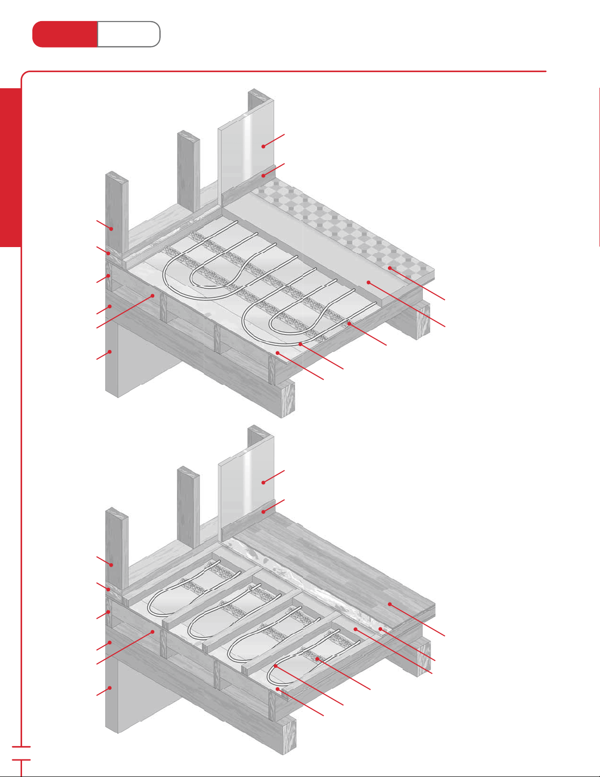
Heat Link
www.heatlink.com
®
“Wet” System
Canada - July 1, 2014
Wall Stud
Radiant Heating & Cooling
Double Plating
Floor Joist
Support Beam
Foil-backed
Insulation
Foundation
or Main Floor
Bearing Wall
Drywall
Baseboard
Tubing Tracking on Sub oor
Installed on top of the sub oor with light
weight concrete.
Floor Covering
Gypsum or Concrete
HeatLink® Tubing Tracking (page 53)
HeatLink® O2 Barrier PEX Tubing (page 5)
Plywood Sub oor
Wall Stud
Double Plating
Floor Joist
Support Beam
Foil-backed
Insulation
Foundation
or Main Floor
Bearing Wall
Drywall
Baseboard
Tubing Tracking on Sub oor
Installed on top of the sub oor with light weight
concrete (shown with sleepers for hardwood
installation).
Hardwood
Floor
Sub oor
Gypsum or Concrete
HeatLink® Tubing Tracking (page 53)
HeatLink® O
Preliminary Sub oor
Barrier PEX Tubing (page 5)
2
48
Page 51
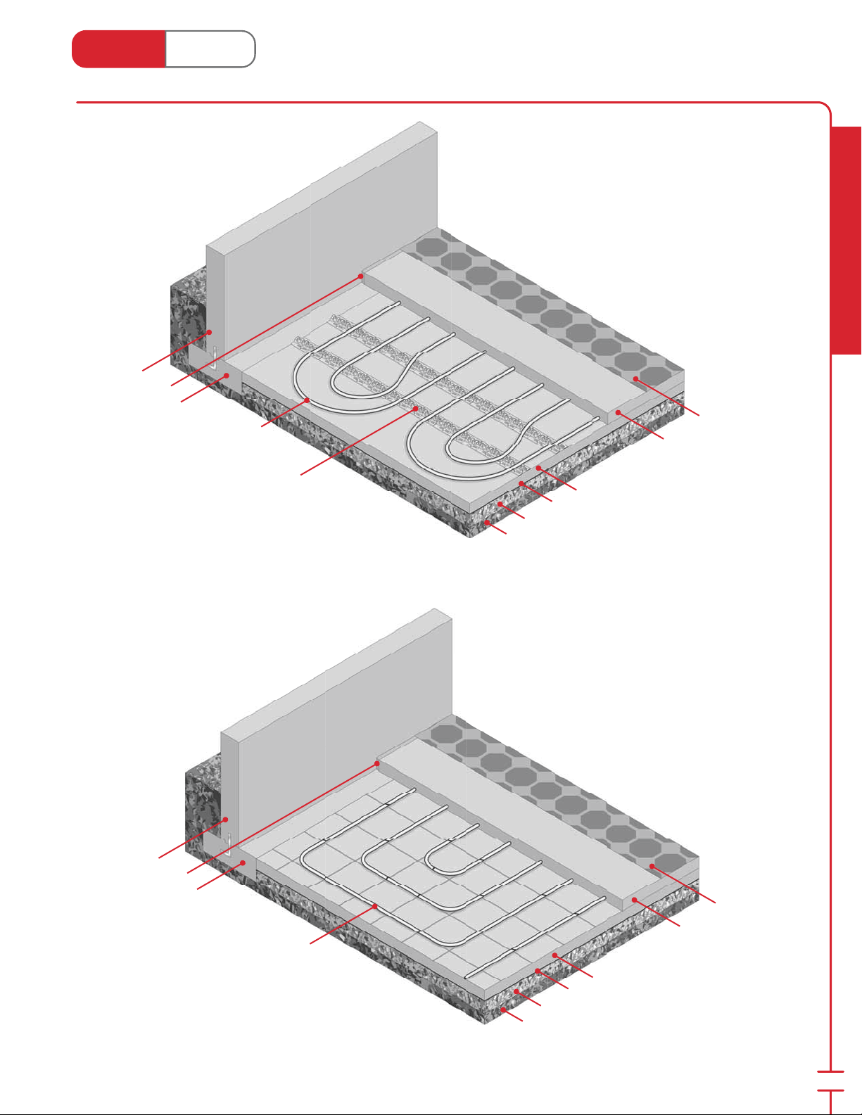
Heat Link
www.heatlink.com
Foundation
Thermal Break
Footing
HeatLink® O
Barrier PEX
2
Tubing (page 5)
®
“Wet” System
Canada - July 1, 2014
Radiant Heating & Cooling
Tubing Tracking on Insulation
Used for basements or slab-on-grade homes.
The PEX tubing is encased in a concrete topping.
Floor Covering
Gypsum or Concrete
HeatLink® Tubing Tracking (page 53)
with Track Staples (page 54)
Foundation
Thermal Break
Footing
HeatLink® O
Barrier PEX Tubing (page 5)
2
with Tie Straps (page 54)
Closed Cell High Density Insulation
Vapor Barrier
Gravel Bed
Subsoil
Tie Strap on Mesh/Rebar
Used for basements or slab-on-grade homes.
The PEX tubing is encased in a concrete topping.
Floor Covering
Gypsum or Concrete
Closed Cell High Density Insulation
Vapor Barrier
Gravel Bed
Subsoil
49
Page 52
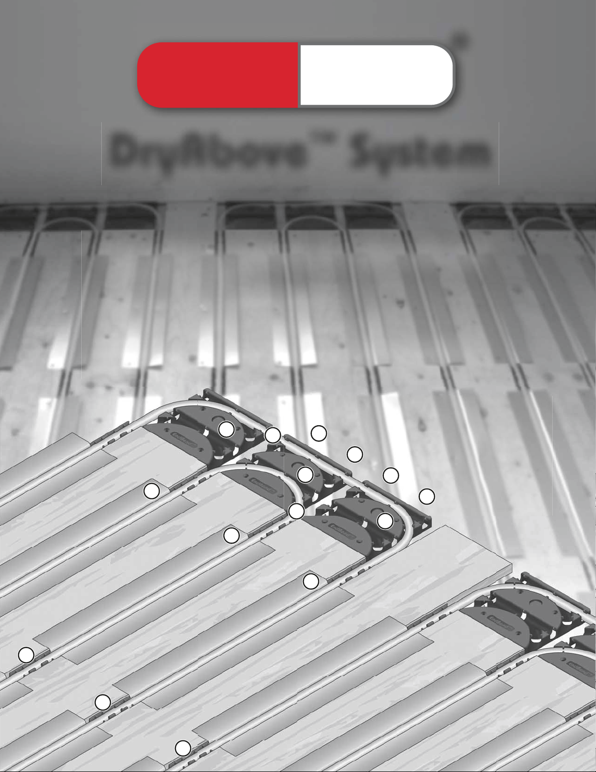
®
Heat Link
™
DryAbove
• Dry system that eliminates the “pain in the neck”
of overhead work
• No structural changes required
System
• Ideal for retrofi ts or remodeling
• Inexpensive components keep material costs low
DryAbove™ components:
1
3
3
4
1
EndBend
2
SpacerClip
1
4
3
™
™
3
Heat Transfer Plate
4
1⁄2” PEX Tubing
1
2
2
2
Page 53
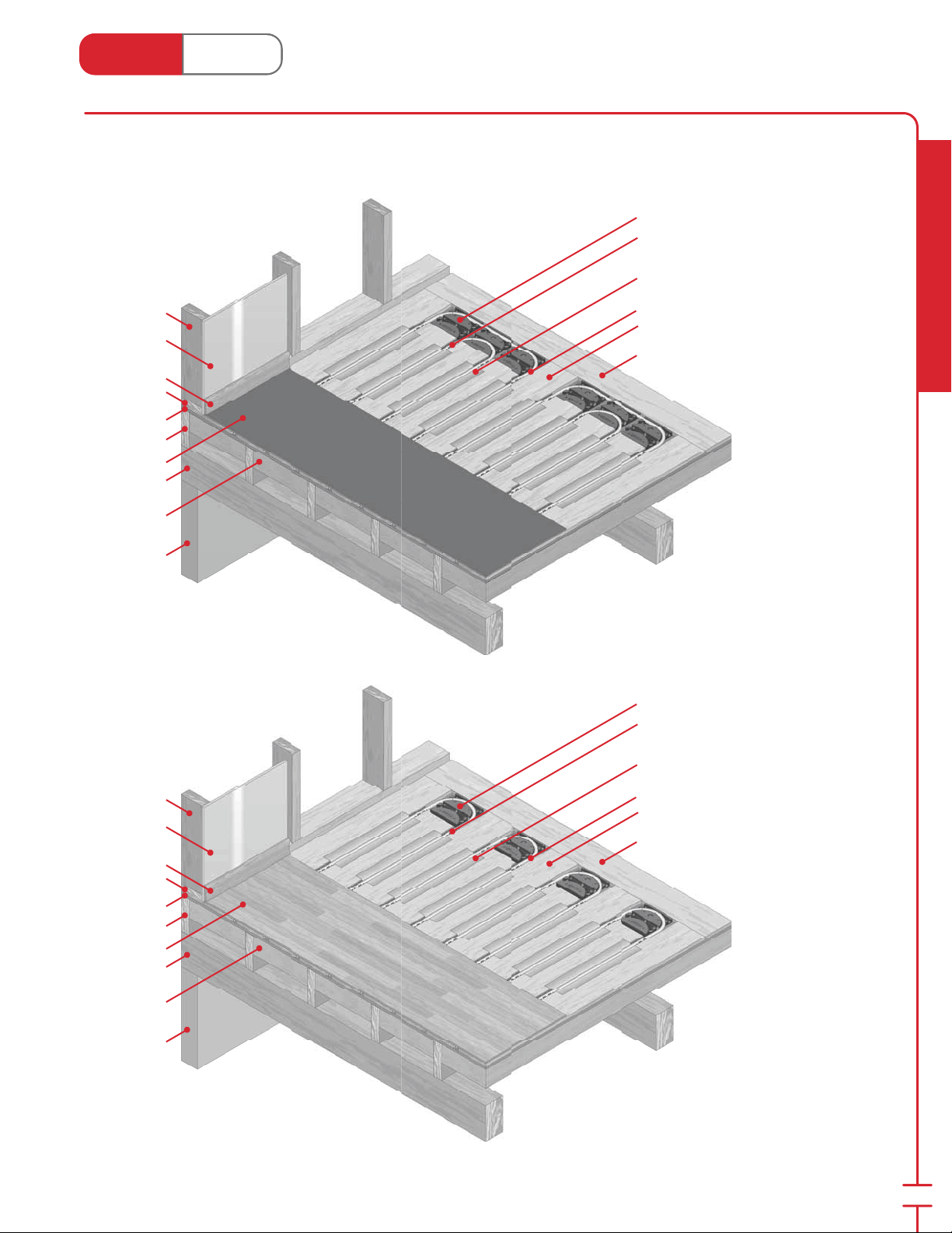
Heat Link
1
www.heatlink.com
®
DryAbove™ System
Canada - July 1, 2014
Double Counter Flow
Installed on top of the sub oor or
existing oors for remodelling or
additions.
Wall Stud
Drywall
Baseboard
Plating
Sub oor
Floor Joist
Floor Covering
Support Beam
Foil-backed
Insulation
Foundation
or Main Floor
Bearing Wall
EndBend™ (page 53)
SpacerClip™ (page 53)
HeatLink® Heat Transfer Plate (page 53)
HeatLink®
(page 7)
Sleepers
Perimeter Edging
⁄2" Non Barrier PEX Tubing
Radiant Heating & Cooling
Wall Stud
Drywall
Baseboard
Plating
Sub oor
Floor Joist
Floor Covering
Support Beam
Foil-backed
Insulation
Foundation
or Main Floor
Bearing Wall
EndBend™ (page 53)
SpacerClip™ (page 53)
HeatLink® Heat Transfer Plate (page 53)
HeatLink® 1⁄2" Non Barrier PEX Tubing
(page 7)
Sleepers
Perimeter Edging
Serpentine
Installed on top of the sub oor or existing
oors for remodelling or additions with solid
hardwood oors.
51
Page 54
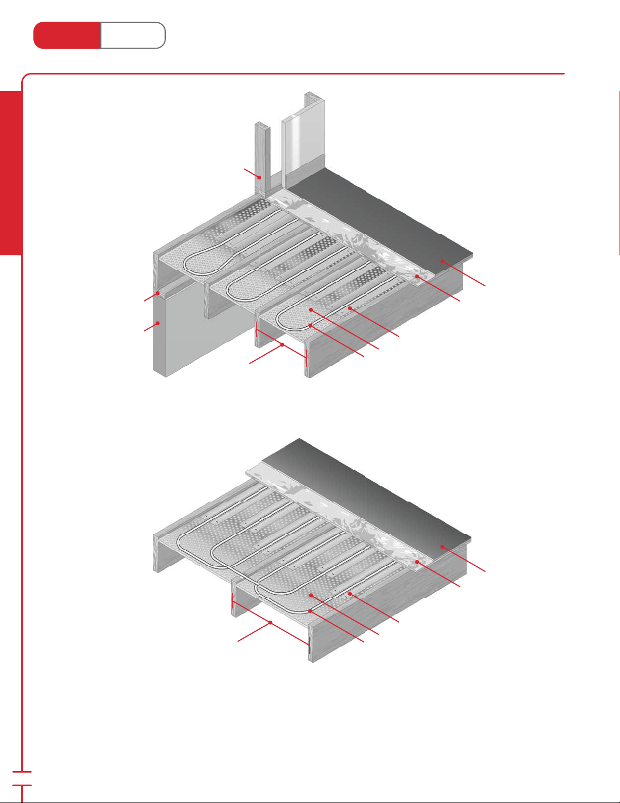
®
Heat Link
www.heatlink.com
Double Loop
Installed between 12"/16" O.C. oor
joists beneath the sub oor for retro ts or
upper oors.
Radiant Heating & Cooling
Sill
DryBelow™ System
Canada - July 1, 2014
Wall Stud
Floor Covering
Plywood Sub oor
Foundation
or Main Floor
Bearing Wall
Triple Loop
Installed between 16"/24" O.C. oor
joists beneath the sub oor for retro ts or
upper oors.
HeatLink® Heat Transfer Plates (page 53)
Re ective Insulation
HeatLink® Non Barrier PEX Tubing (page 7)
12" / 16" O.C.
Joist Space
Floor Covering
Plywood Sub oor
52
16" / 24" O.C.
Joist Space
HeatLink® Heat Transfer Plates (page 53)
Re ective Insulation
HeatLink® Non Barrier PEX Tubing (page 7)
Page 55
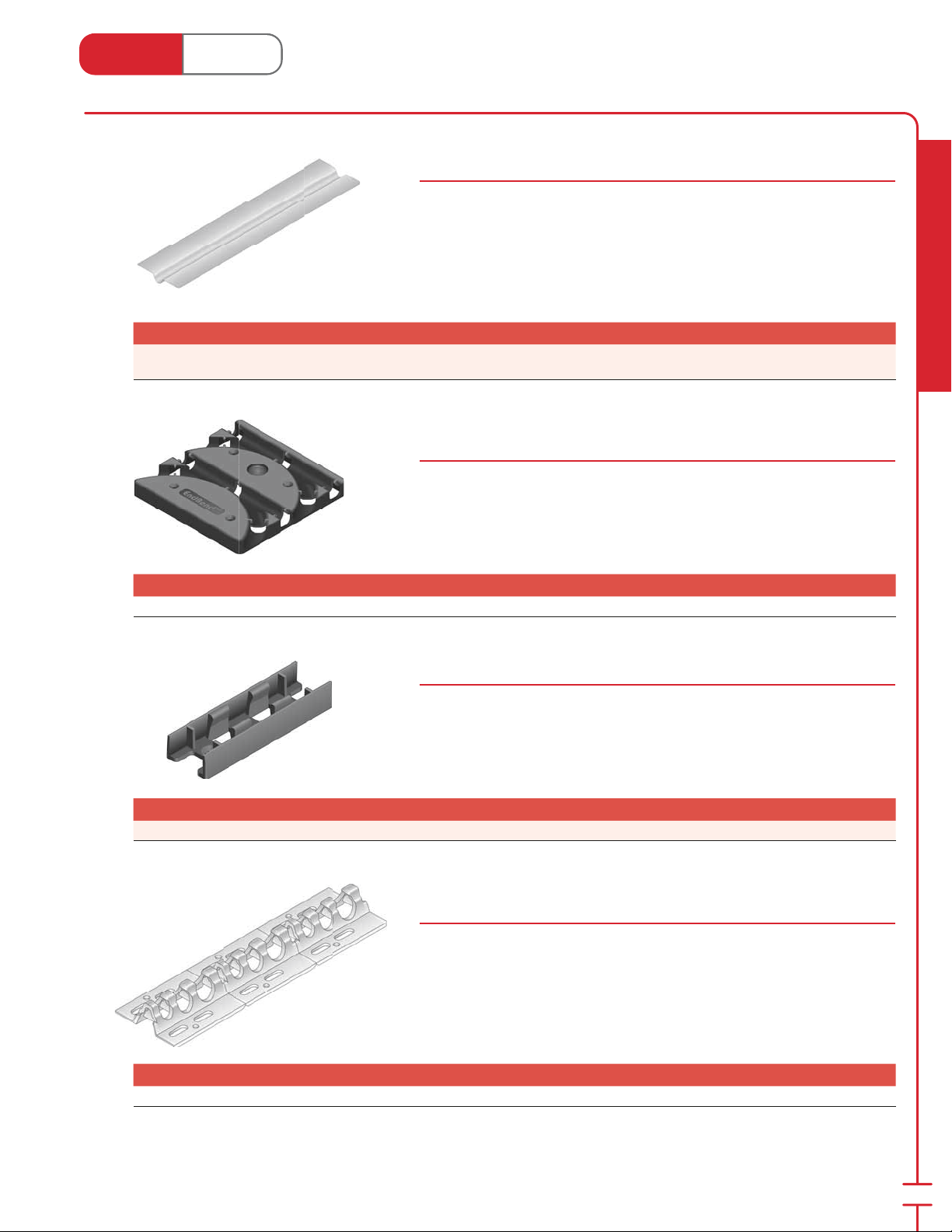
Heat Link
www.heatlink.com
®
Floor Heating Accessories
Canada - July 1, 2014
Aluminum Heat Transfer Plate
Stk# 87024
This plating is used to provide a direct transfer and heat dis tri bu tion from the PEX
piping to a wooden sub oor. They can be stapled to the underside of the sub oor
in a DryBelow™ system or used above the sub oor in a DryAbove™ system.
End to end gaps between plates should be from 3" to 6" (75 to 150mm).
Plates measure 24" × 4-1⁄4" (610 mm × 108 mm).
Stk# Description Pkg Qty Carton Qty Unit List Price / Unit
87024
24" Aluminum Heat Transfer Plate for DryAbove™/
DryBelow™ Systems
250 6000 ea.
EndBend™ for DryAbove™ System
Stk# 87205
The EndBend™ allows for transition on the loop ends as well as supports for
supply & return piping.
Stk# Description Pkg Qty Carton Qty Unit List Price / Unit
87205 EndBend™ for DryAbove™ System 25 50 ea.
Radiant Heating & Cooling
SpacerClip™ for DryAbove™ System
Stk# 87305
The SpacerClip™ is placed between the heat transfer plates and holds the tubing
in place. Tubing can be stepped into clip.
Stk# Description Pkg Qty Carton Qty Unit List Price / Unit
87305 SpacerClip™ for DryAbove™ System 50 500 ea.
Tubing Tracking: 3⁄8", 1⁄2" and 5⁄8"
Stk# 89000
Tracking provides even tubing spacing and exact reg u la tion of tubing heights.
They can be fastened to many surfaces, such as concrete or plywood sub oors,
steel Q deck ing, and polystyrene in su la tion. Built in sup ports permit spacing in 3"
(75 mm) multiples.
Tracking comes in 4 ft (1.22 m) lengths.
Stk# Description Pkg Qty Carton Qty Unit List Price / Unit
89000 Tubing Tracking 400 10000 ft.
53
Page 56
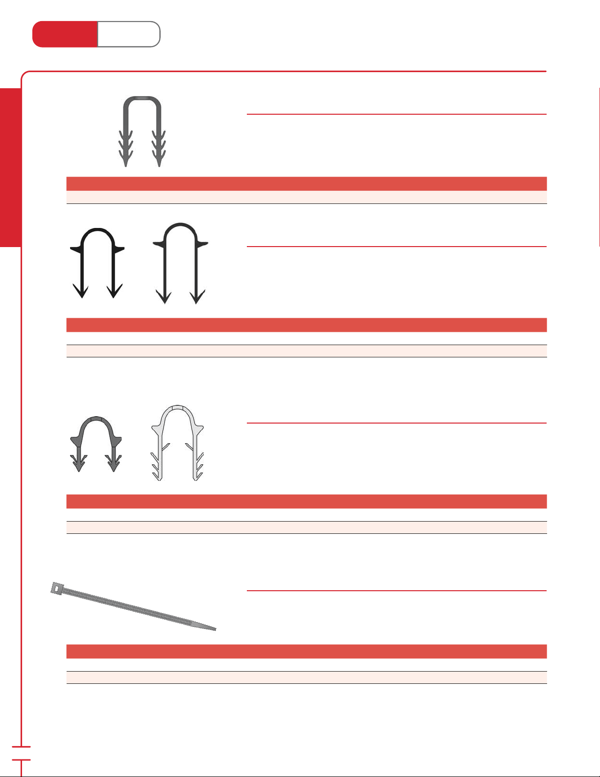
Heat Link
3
www.heatlink.com
Stk# Description Pkg Qty Carton Qty Unit List Price / Unit
89010 500 Track Staples 1 18 bag
®
Floor Heating Accessories
Canada - July 1, 2014
Track Staples
Stk# 89010
Staples are used to fasten tubing tracking to polystyrene insulation. The hooks on
the ends ensure the staple will not loosen prior to topping pour.
Radiant Heating & Cooling
Stk# Description Pkg Qty Carton Qty Unit List Price / Unit
89243 250× 2" (50mm) HeatLink® Staples for Stand-up Stapler 1 16 box
89244 300× 2-
Stk# Description Pkg Qty Carton Qty Unit List Price / Unit
89251 300× 1-1⁄2" Staples for HeatLink® Deluxe Staple Gun 1 20 box
89252 300× 2" Staples for HeatLink® Deluxe Staple Gun 1 box
Staples for Stand-up Stapler
89240 Series
Staples for fastening up to 1⁄2" (or 18mm O.D.) PEX tubing to polystyrene
insulation. For use with Stand-up Stapler #10220 (discontinued).
⁄8" (60mm) Staples for Stand-up Stapler 1 12 box
Staples for Deluxe Staple Gun
89250 Series
Staples for fastening up to 5⁄8" (or 20mm O.D.) PEX tubing to polystyrene
insulation. For use with HeatLink® Deluxe Staple Gun #10230 (page 143).
54
HeatLink® Tie Straps
89100 Series
Used to fasten piping to wire mesh or rebar. 5-1⁄2" (140 mm) tie wraps (89105) are
used for smaller diameter tubing. 7-1⁄2" (190 mm) tie wraps (89107) can be used for
sizes up to 1".
Stk# Description Pkg Qty Carton Qty Unit List Price / Unit
89105 1000 Tie Straps - 5.5" 1 10 bag
89107 1000 Tie Straps - 7.5" 1 10 bag
Page 57
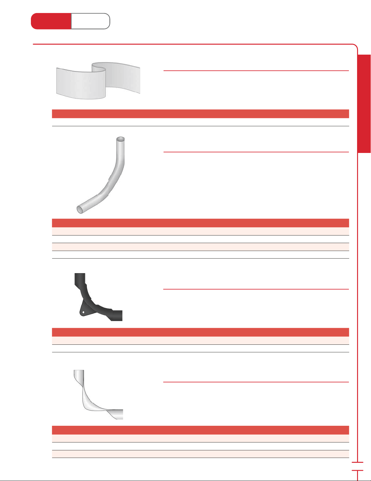
Heat Link
1
5
3
3
5
3
www.heatlink.com
®
Floor Heating Accessories
Canada - July 1, 2014
Expansion Stripping
Stk# 85000
This foam stripping provides expansion joint and sound barrier at the edge of the
oor slab.
Roll of 75 ft (23 m)
Stk# Description Pkg Qty Carton Qty Unit List Price / Unit
85000 75ft Roll Expansion Stripping 1 17 roll
Conduit Elbows
86000 Series
High impact strength moulded plastic 90° long radius elbow, designed to direct
and protect heating tubing in transition area where tubing enters and exits
concrete slab.
Stk# Description Pkg Qty Carton Qty Unit List Price / Unit
86005
86020
86022
86028 1" Conduit 90's 1 100 ea.
⁄2" Conduit 90's 1 100 ea.
⁄8" Conduit 90's 1 50 ea.
⁄4" Conduit 90's 1 40 ea.
Radiant Heating & Cooling
Plastic Bend Support
86100 Series
Allows for easy bending support and removal.
Stk# Description Pkg Qty Carton Qty Unit List Price / Unit
86105 Plastic Bend Support for 3⁄8" and 1⁄2" Tubing 50 400 ea.
86122 Plastic Bend Support for
⁄4" Tubing 10 400 ea.
Metal Bend Support
86200 Series
Allows for easy bending support and removal.
Stk# Description Pkg Qty Carton Qty Unit List Price / Unit
86205 Metal Bend Support for 1⁄2" Tubing 50 200 ea.
86219 Metal Bend Support for
86222 Metal Bend Support for
⁄8" Tubing 50 200 ea.
⁄4" Tubing 25 100 ea.
55
Page 58
Heat Link
www.heatlink.com
Radiant Heating & Cooling
Stk# Description Pkg Qty Carton Qty Unit List Price / Unit
01205 1L Corrosion Inhibitor (Molybdate Based) 1 bottle
®
Chemicals
Canada - July 1, 2014
Molybdate Based Corrosion Inhibitor
Stk# 01205
The Molybdate Based Corrosion Inhibitor creates a protective monomolecular
lm over all internal surfaces of the heating system as the water circulates. The
lm is an anodic coating which immediately stops corrosive attack of the metallic
parts. Molybdate will not harm PEX tubing or the manifolds and it is glycol
compatible. Molybdate concentration between 100-150 ppm is recommended;
higher concentrations are not harmful.
The Molybdate will act as a preoperational cleaner if a sidestream lter is
installed and double the amount of Molybdate required is added. The molybdate
concentration should be checked after this procedure.
The contents of this 1 L (0.26 US gal) container will treat 182 L (48 US gal) of water.
Advantages: low toxicity; non-pollutant; non-staining
Purging Compound (Pre & Post Operational Cleaner)
Stk# 01311
Purging compound for boilers and closed loop systems. Used as a preoperational
cleaner and a post start-up cleaner.
The contents of this 1 L (0.26 US gal) container will treat 33 L (9 US gal) of water.
Note: After re lling system with fresh water, ensure either a glycol or inhibitor is
immediately added.
Stk# Description Pkg Qty Carton Qty Unit List Price / Unit
01311 1L Purging Compound (Pre & Post Operational Cleaner) 1 bottle
Postoperational Filtration Cleaner
Stk# 01321
Scale conditioning additive. Must be used in conjunction with a sidestream lter.
Polymer based additive that promotes movement of precipitate into the lter.
System can be cleaned while still in operation.
The contents of this 1 L (0.26 US gal) container will treat 1000 L (264 US gal) of
water.
56
Stk# Description Pkg Qty Carton Qty Unit List Price / Unit
01321 1L Postoperational Filtration Cleaner 1 L
Page 59
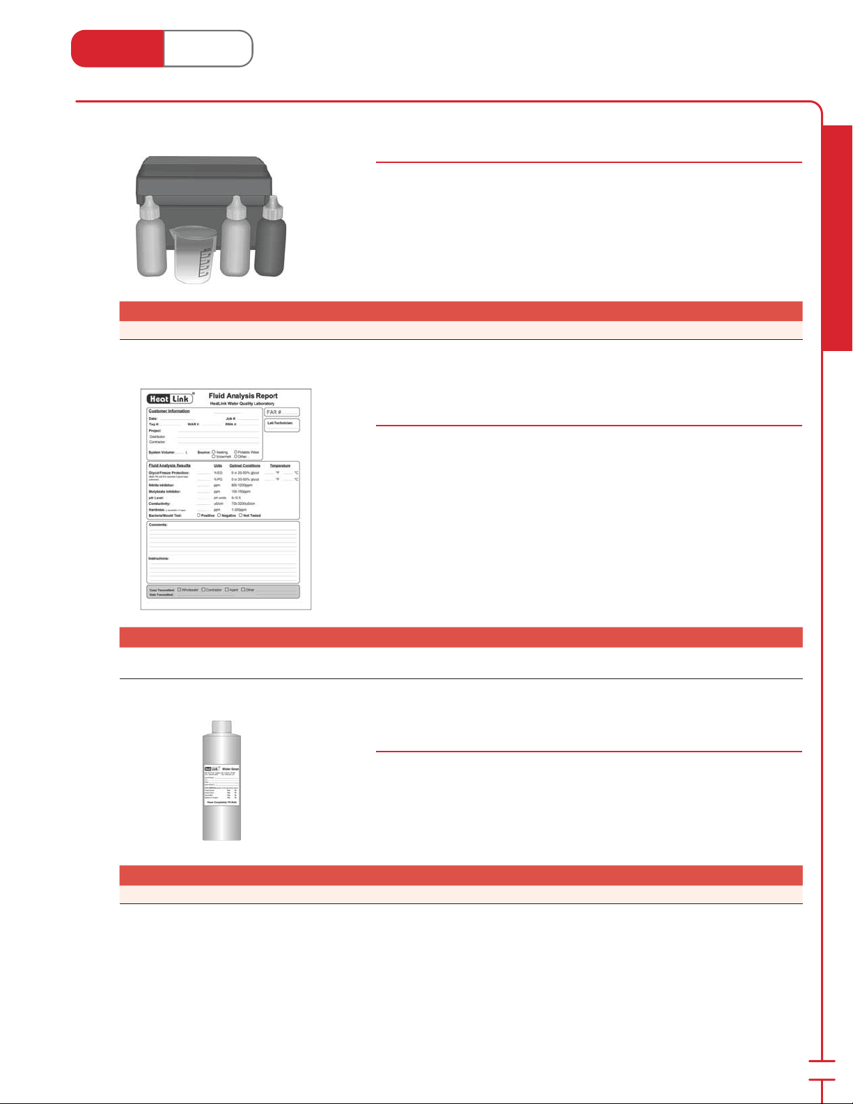
Heat Link
www.heatlink.com
®
Water Testing
Canada - July 1, 2014
Molybdenum Test Kit
Stk# 01020
Determines the amount of molybdate based corrosion inhibitor in the water.
Includes:
• 50 mL plastic beaker
• Molybdenum titrating solution
• Molybdenum bu er solution
• Mixed indicator solution
Note: Chemicals included have expiry dates
Stk# Description Pkg Qty Carton Qty Unit List Price / Unit
01020 Molybdenum Test Kit 1 ea.
HeatLink Preventative Maintenance Water Analysis
Stk# 00412
Water analysis service provided by HeatLink that tests a water sample for:
• Glycol
• Nitrite Inhibitor
• Molybdate Inhibitor
• pH Level
• Conductivity
• Hardness
A water sample of 400-500 mL (13.5-17 . oz.) in a clean plastic bottle (e.g. wsb2)
is required.
Radiant Heating & Cooling
Stk# Description Pkg Qty Carton Qty Unit List Price / Unit
Stk# Description Pkg Qty Carton Qty Unit Net Price / Unit
00412
HeatLink Preventative Maintenance Water Analysis
(requires wsb2)
1 ea.
#2 Water Sample Bottle w/cap - General
Stk# wsb2
Plastic bottle for collecting a water sample.
Stk# Description Pkg Qty Carton Qty Unit List Price / Unit
Stk# Description Pkg Qty Carton Qty Unit Net Price / Unit
wsb2 #2 Water Sample Bottle w/Cap - General 1 24 ea.
57
Page 60
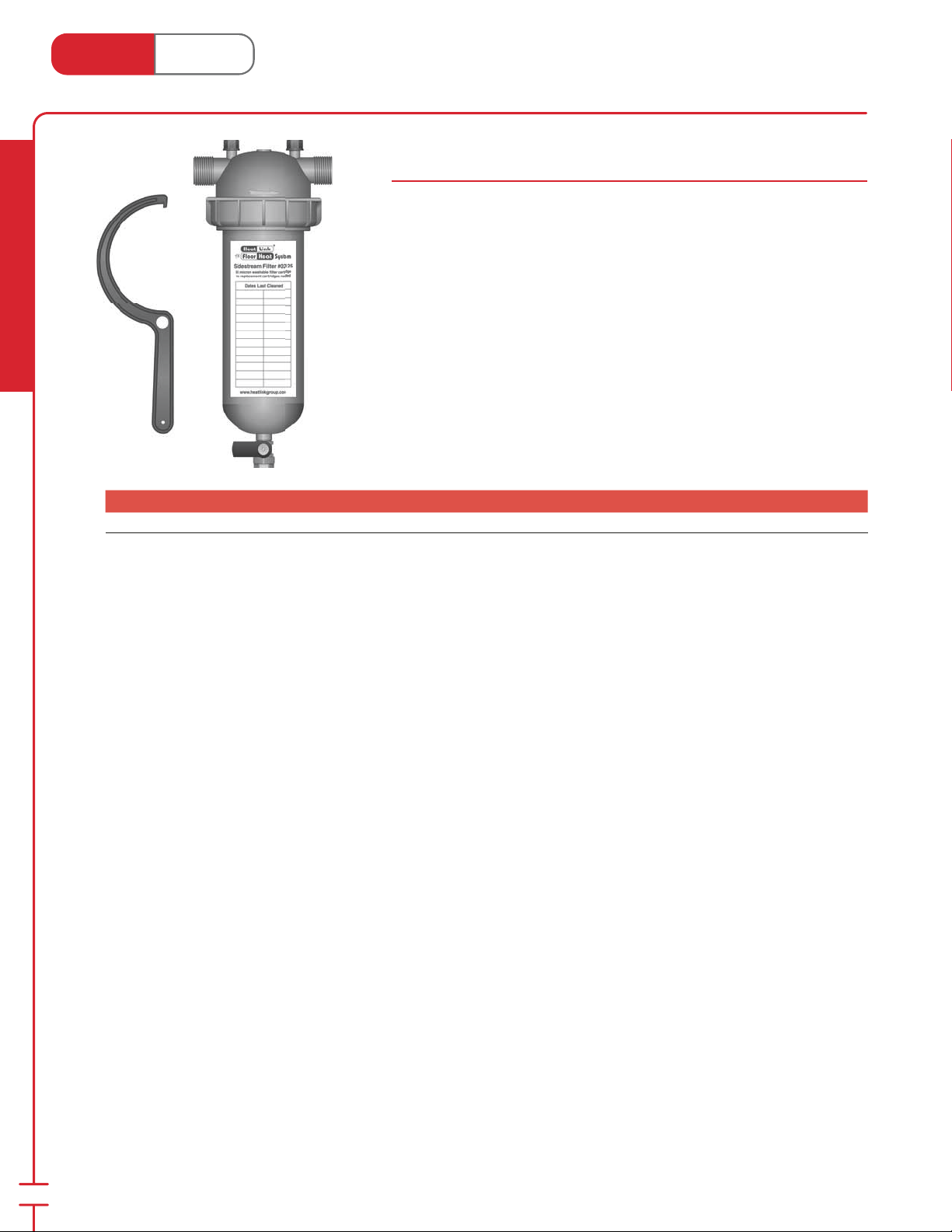
Heat Link
www.heatlink.com
Radiant Heating & Cooling
®
Side Stream Filter
Canada - July 1, 2014
Side Stream Filter
Stk# 02125
The HeatLink® side stream lter is designed to remove precipitate (suspended
solids) from the system uid. Precipitate can lead to increased wear and tear of
components and decreased system e ciency.
The 02125 lter (made of reinforced polypropylene) is chemically resistant to
propylene & ethylene glycol and both molybdate and nitrite inhibitors.
The 55 micron lter cartridge is easily cleaned and reusable, no replacement
cartridges are necessary.
For use on systems up to 600,000 BTU. One size ts all.
1" male NPT thread connections.
Stk# Description Pkg Qty Carton Qty Unit List Price / Unit
02125 1" Side Stream Filter 1 ea.
58
Page 61
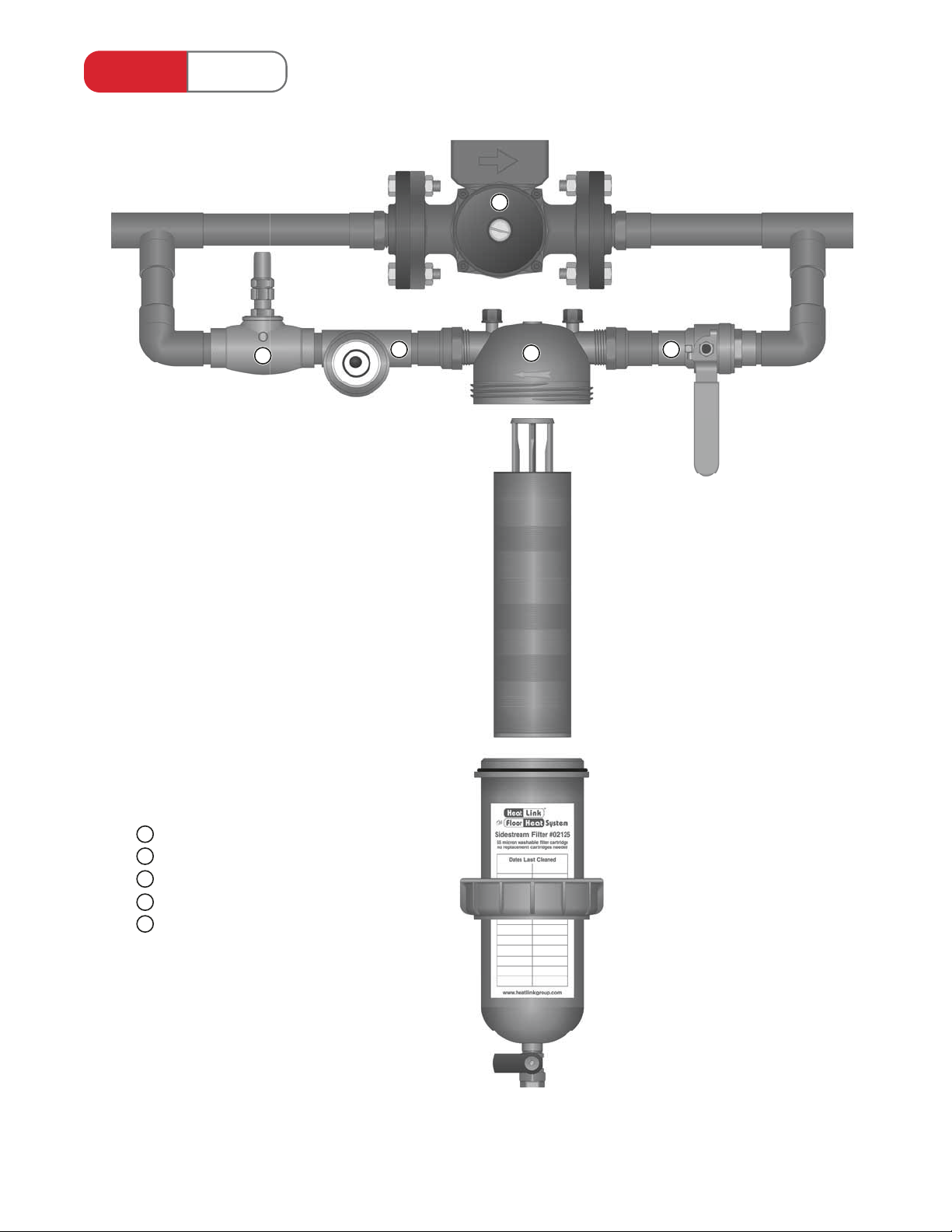
®
Heat Link
4
• Cleans system uids.
• Extends life of heating system.
• Protects o-rings and seals.
Side Stream Filter
5
3
1
2
• Maintains system e ciency.
• The 55 micron lter cartridge is
easily cleaned and reused. No
replacement cartridges are needed.
• For use in residential and
commercial applications.
• For use on systems up to 600,000
BTU. One size ts all.
Components
1
HeatLink® Side Stream lter (#02125)
2
Isolation (ball) valve
3
Flow Indicator
HeatLink® Balancing valve (#62325)
4
5
Low Temp. System Pump
The 55 micron lter is a column of
stacked disks designed to remove
precipitates as water passes through.
There are no replacement lter
cartridges to buy, as the disk system is
easily removed, cleaned under a stream
of warm water, and simply reinserted.
Page 62
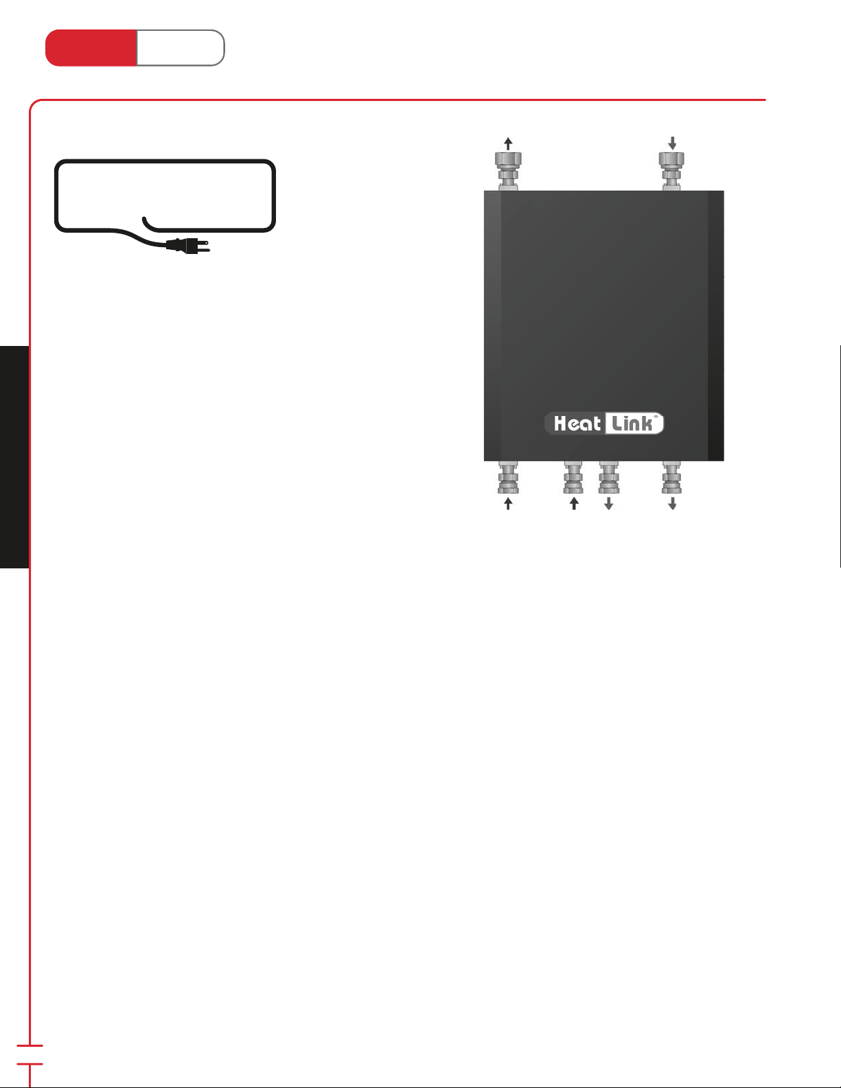
®
Heat Link
www.heatlink.com
™
MECHANICAL
ROOM IN A BOX
Making the Complex Simple
HeatLink has found a way to make the complex more simple.
With the Mechanical Room in a Box, some of the most common
components of a radiant hydronic installation (mainly the wiring,
pumps, and mixing valves), are installed on a panel with a plug,
and boxed with a steel cover. This pre-wired, pre-fabricated, preengineered box is a time and money saving way to add control and
consistency to an installation. Plug it in, and presto…you’ve got play!
Introduction
Canada - July 1, 2014
Features
• Versatile solutions for simple or complex hydronic heating
applications.
• Pre-fabricated, pre-engineered, pre-wired…pre-cise!
• High quality, reliable and standardized construction.
• Modular approach for ease of installation.
• Appliance-like protective steel cover; tamper-resistant.
Mechanical Room in a Box
• Closed hydronic systems can be extensively zoned.
• Solar energy sources can be seamlessly added.
• When properly piped, there is less component cycling…and more silence.
Advantages
• Pre-engineered solutions reduce design and quotation time.
• Reliable (ETL listed, UL 508, CSA standard), exceeds highest quality standards, with multiple test procedures for
electrical and mechanical system components.
• Eliminate on-site design and reduced risk of on-site errors.
• Known cost; fewer surprises.
• Reduced installation times; time is money!
• Trouble-free start-ups every time!
• Fewer call-backs.
• Compact and aesthetically pleasing.
• Easily serviced and replaceable.
• Covered by a single warranty.
60
Page 63
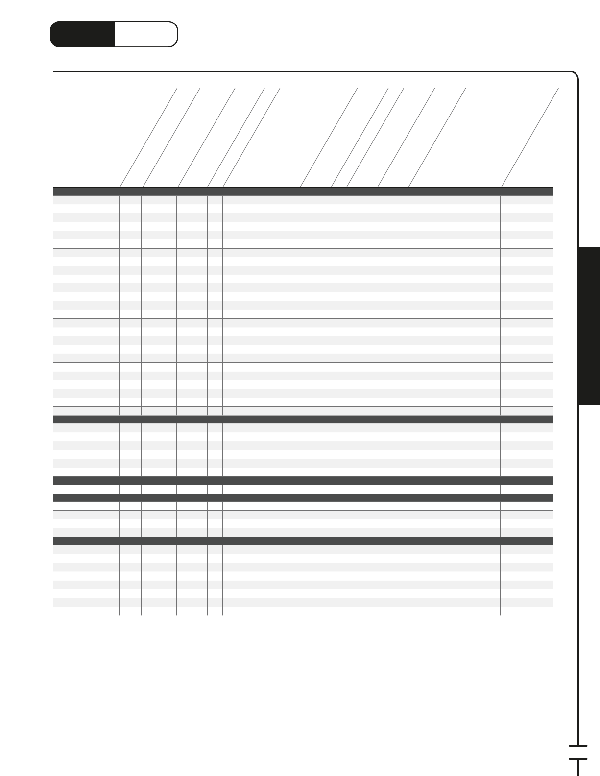
®
LinkHeat
www.heatlink.com
Page #
For use in open system
For use in closed system
Nominal Output (MBH)
Heat Source Built-in
Panel Stk#
Small House, Garage, Apartments
ECO1ZN3P 62
ECO2ZN4P 62
V101 64
V102 64
CAD01 66
CAD02 66
ELBP30 68
ELBP30TS3 70
ELBP30TS5 70
ELBP50 68
ELBP50TS7 70
TMP040 72
TMP070 72
TMP070Z 74
TMP085DP 76
TMP200DT 78
TWH070 80
TWH070P 82
TWH070XP 82
TWH070Z 84
TWH070XPZ 84
HEP025P 86
HEP080P 86
HEP095P 88
WHP130P 90
Large House
CDP200R2 92
CDP220R2 94
CDP250R2 94
CDP250P3R2 94
CDP310RP3R2 96
CDP310RP4R2 96
Solar
SOL080 98
Commercial
SSM Series 100
SSP Series 102
SSTS Series 104
SSTL Series 106
Snow Melting
SMP375SS 108
SMP375SSH 108
SMP175SS-HEX 110
SMP300SS-HEX 110
SMP300SS-HEX-H 110
SMP400D 112
SMP335 114
SMP425 114
* CDP200R2 panel branch and pump can be used for either DHW or high temp, but not both
✔✔
✔✔
✔✔
✔✔
✔✔
✔✔
✔✔
✔✔
✔✔
✔✔
✔✔
✔✔
✔✔
✔✔
✔
80 All
✔
100 All
✔
80 All
✔
100 All
✔
80 All
✔
100 All
✔
30
✔
30
✔
30
✔
50
✔
50
✔
40
70
70
85
200
70
70
70
70
70
25
80
95
130 opt
200
✔
220
✔
250
✔
250
✔
310
✔
310
✔
80
✔✔
✔✔
✔✔
✔✔
300
✔
375
✔
175
✔
300
✔
365
✔
400
✔
335
✔
425
✔
3-way Mixing Valve
✔ ✔
✔✔ ✔
✔✔ ✔
✔ ✔
✔✔ ✔
✔✔ ✔ ✔✔
✔✔ ✔ ✔✔
✔✔ ✔✔ ✔✔
✔✔ ✔ ✔✔
✔✔ ✔✔ ✔ ✔✔
✔✔ ✔✔✔✔
✔✔
✔✔
✔✔ ✔✔✔ ✔✔
✔✔ ✔✔✔ ✔✔
✔✔ ✔
✔✔ ✔ ✔✔✔ ✔✔✔✔✔
✔✔ ✔ ✔✔✔ ✔✔✔✔✔
✔✔ ✔ ✔✔ ✔✔✔✔✔
✔ ✔ ✔ ✔✔ ✔✔✔✔✔
✔ ✔ ✔ ✔✔✔ ✔✔✔✔✔
✔✔ ✔
✔✔ ✔
✔✔✔ ✔
✔✔✔ ✔
✔✔✔ ✔
✔✔ ✔
✔✔✔ ✔
✔✔✔ ✔
Thermostatic Head
opt opt
opt
Reset Mixing
DHW Priority
Heat Exchanger
opt
opt
opt
✔
opt
✔
opt
✔
✔✔✔✔
Distribution Manifold
***
✔
✔
DHW Branch & Pump
High Temp Branch
Distribution Header
System Panel Selection
Canada - July 1, 2014
High Temp Pump
For use with Tankless Water Heater
Open System Zoning
✔✔✔✔
✔✔✔✔
✔✔✔✔
✔✔✔✔
✔✔✔✔
Purge Timer
24hr Timer for Potable Applications
✔✔✔
✔✔✔✔
Aux Dry Contacts for Space Heating
Bypass Function
Pump Check Valve
Aux Dry Contacts for High Temp
Aux Dry Contacts for DHW
Both
Both
Primary only
Primary only
Primary only
Primary only
Primary only
All
All
All
All
All
All
Mechanical Room in a Box
61
Page 64
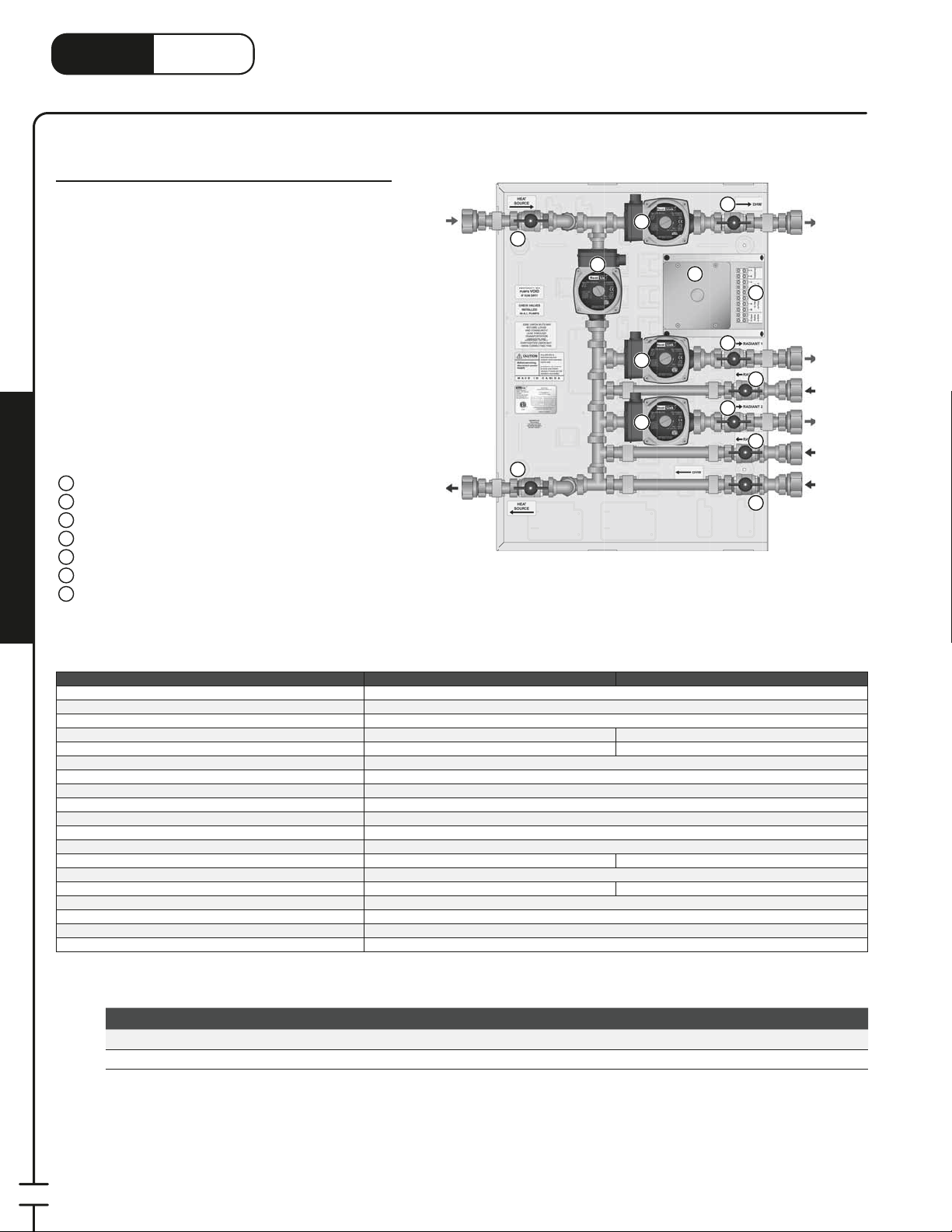
LinkHeat
1
3
www.heatlink.com
ECO Boiler Panels
ECO Series
®
ECO Boiler Panels
Canada - July 1, 2014
ECO2ZN4P
These panels are designed to work with Weil-McLain ECO
boilers. The primary piping matches up to the ECO boiler
system supply and return. The cool gray color of the
enclosure matches the ECO boiler.
The panel has three or four Grundfos UPS15-58 pumps.
There is a primary pump, a DHW water pump and one or
two heating pumps. The primary and DHW pumps are
controlled by the boiler. On the ECO Boiler Panel model,
the heating pump is controlled by a thermostat (supplied
separately) wired to the boiler. On the ECO Boiler Panel
High Capacity model, each heating pump is controlled by
a thermostat (supplied separately) wired to the terminal
strip on the panel. The water temperature is controlled by
the boiler.
Panel Components
1
Primary Pump
2
DHW Pump
Radiant 1 Pump
3
Radiant 2 Pump (ECO2ZN4P only)
4
Electrical Connection Box
5
24V Terminal Strip (ECO2ZN4P only)
6
Isolation Valve
7
Panel Enclosure (not shown)
;
Mechanical Room in a Box
Primary
Supply
Primary
Return
7
2
7
1
3
4
7
5
6
7
7
7
7
7
DHW
Supply
Radiant 1
Supply
Radiant 1
Return
Radiant 2
Supply
Radiant 2
Return
DHW
Return
Listing cETLus
Conforms to CAN/CSA-C22 No.14, UL508
Dimensions
Nominal panel output 80,000 btu/hr 100,000 btu/hr
Nominal ow 6.0 US gpm @ 35°F ΔT 10.0 US gpm @ 35°F ΔT
Max ambient temperature 120°F (49°C)
Min operating temperature 40°F (4°C)
Max operating temperature 200°F (93°C)
Max operating pressure 125 psi (862 kPa)
Power requirements 120 V(ac)/24 V(ac) 60 Hz
Primary pump Non-ferrous, Grundfos UPS15-58
Radiant 1 pump Non-ferrous, Grundfos UPS15-58
Radiant 2 pump n/a
DHW pump Non-ferrous, Grundfos UPS15-58
Auxiliary terminal n/a 1 dry contact, max. load 1.5A
Piping
Piping connections 1" FNPT
Backplate 16 gauge galvanized steel
Enclosure Powder coated steel
ECO1ZN3P ECO2ZN4P
26-
⁄4"H × 19-1⁄2"W × 7-1⁄8"D
Non-ferrous,Grundfos UPS15-58
⁄4" 304 SS tubing
Stk# Description Pkg Qty Carton Qty Unit List Price / Unit
New!
New!
ECO1ZN3P ECO Boiler Panel 1 10 ea.
ECO2ZN4P ECO Boiler Panel High Capacity 1 10 ea.
62
Page 65
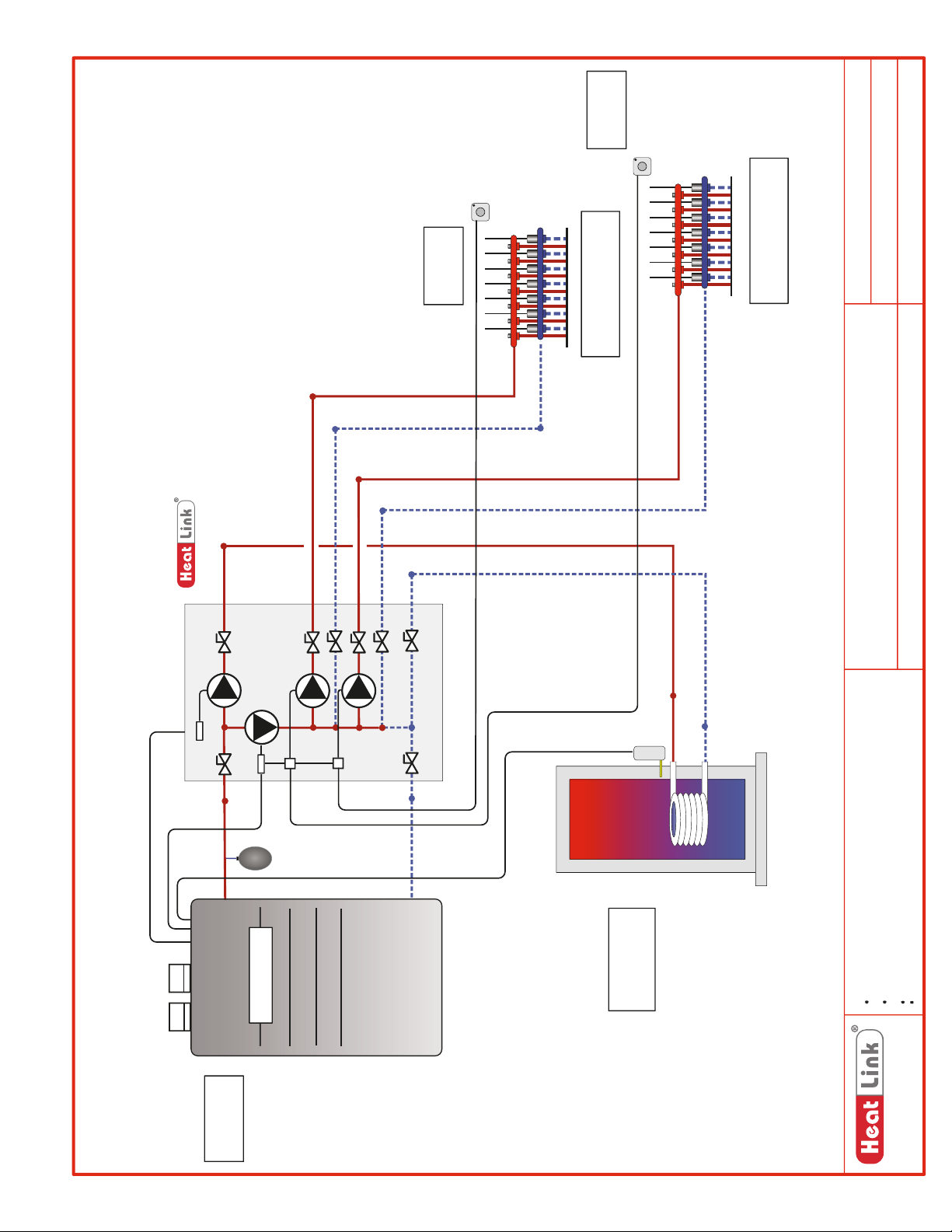
Room
Thermostat
NOTE
All Pumps with
Check Valves
DHW
Circ
Circ
Primary
Circ
Radiant
Circ
Radiant
Room
Thermostat
For Remote Manifolds.
Heating Supply & Return
For Remote Manifolds.
Heating Supply & Return
SCH-ECO-M002
SCH-ECO-E002
SCH-MRIB-R001
Schematic #:
Wiring detail see:
Rough-in wiring see:
Weil-McLain ECO Boiler
ECO2ZN4P
IFHWH, Radiant Heating
2014-05-09
Panel(s):
Heat Source:
Heat Load(s):
Date:
LNG
LNG
BOILER
Weil Mclain
DHW TANK
Drawings are for HeatLink suggested system layout only! User must determine
if system layout will work for their particular application.
Air vents, expansion tanks, pressure relief valves, etc. for heat source as per
local codes.
Use isolation ball valves for all circuits and components.
Notes:
Local codes, regulations, and authorities have final jurisdiction.
1-866-661-5332
www.heatlinkgroup.com
63
Page 66
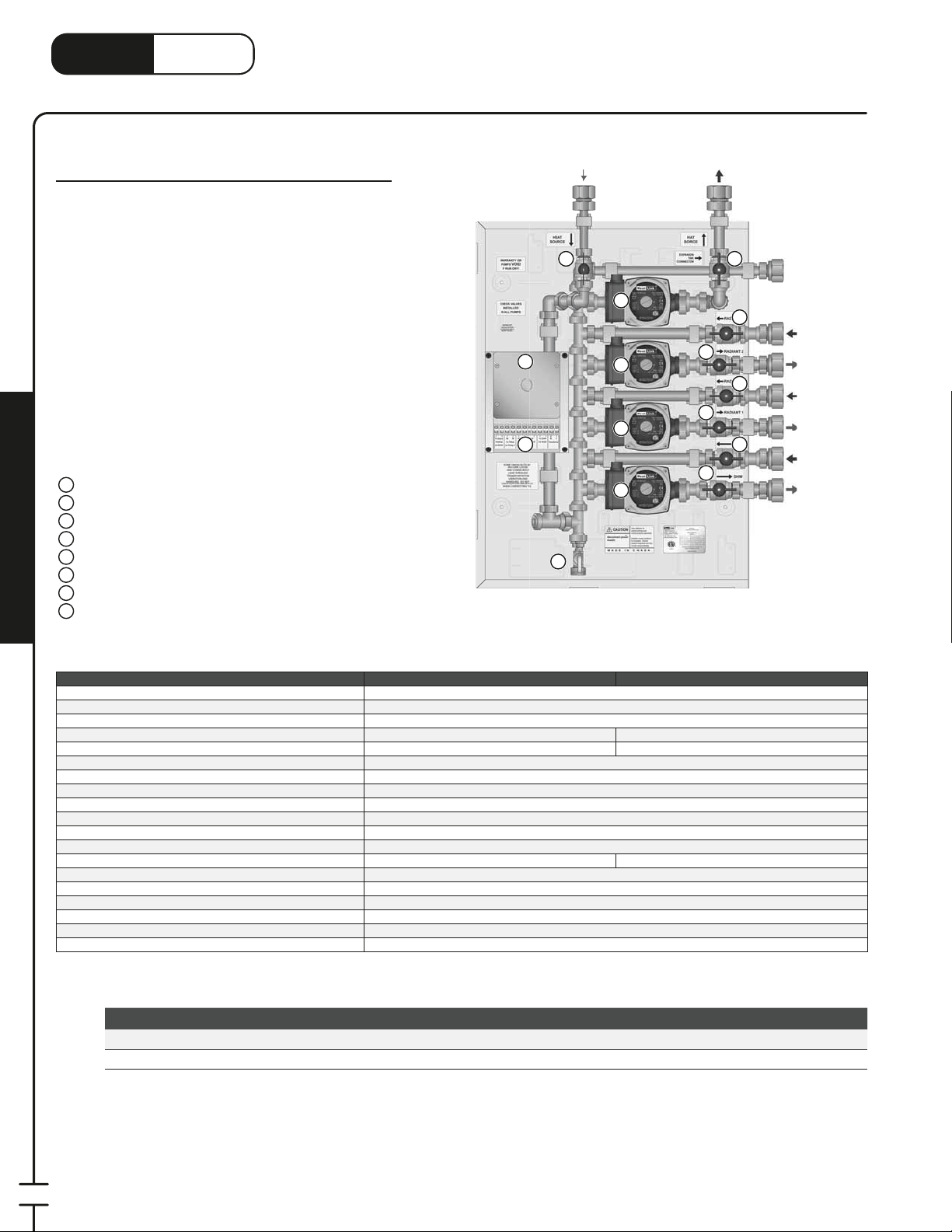
LinkHeat
1
3
www.heatlink.com
®
V100 Boiler Panels
Canada - July 1, 2014
V100 Boiler Panels
V100 Series
These panels are designed to work with Viessmann
Vitodens 100-W boilers. The panel primary piping
matches up to the Vitodens boiler system supply and
return. The white color of the enclosure matches the
Vitodens 100-W boiler.
The panel has three or four Grundfos UPS15-58 pumps.
There is a primary pump, a DHW water pump and one or
two heating pumps. The primary pump is controlled by
the boiler. The DHW pump is controlled by an aquastat
(third party) wired to the terminal strip on the panel. Each
heating pump is controlled by a thermostat (supplied
separately) wired to the terminal strip on the panel. The
water temperature is controlled by the boiler.
Panel Components
Primary Pump
1
DHW Pump
2
Radiant 1 Pump
3
Radiant 2 Pump (V102 only)
4
Electrical Connection Box
5
24V Terminal Strip
6
7
Isolation Valve
8
Drain Valve
Mechanical Room in a Box
Panel Enclosure (not shown)
;
V102
Primary
Supply
7 7
1
5
6
8
4
3
2
Primary
Return
7
7
7
Expansion
Tank
7
7
7
Radiant 2
Return
Radiant 2
Supply
Radiant 1
Return
Radiant 1
Supply
DHW
Return
DHW
Supply
Listing cETLus
Conforms to CAN/CSA-C22 No.14, UL508
Dimensions 26Nominal panel output
Nominal ow
Max ambient temperature 120°F (49°C)
Min operating temperature 40°F (4°C)
Max operating temperature 200°F (93°C)
Max operating pressure 125 psi (862 kPa)
Power requirements 120 V(ac)/24 V(ac) 60 Hz
Primary pump Non-ferrous, Grundfos UPS15-58
Radiant 1 pump Non-ferrous, Grundfos UPS15-58
Radiant 2 pump n/a
DHW pump Non-ferrous, Grundfos UPS15-58
Auxiliary terminal 2 dry contacts, max. load 1.5A
Piping
Piping connections 1" FNPT
Backplate 16 gauge galvanized steel
Enclosure Powder coated steel
V101 V102
80,000 btu/hr
6.0 US gpm @ 35°F ΔT
⁄4"H × 19-1⁄2"W × 7-1⁄8"D
⁄4" 304 SS tubing
Non-ferrous, Grundfos UPS15-58
Stk# Description Pkg Qty Carton Qty Unit List Price / Unit
New!
New!
V101 V100 Boiler Panel 1 ea.
V102 V100 Boiler Panel High Capacity 1 ea.
100,000 btu/hr
10.0 US gpm @ 35°F ΔT
64
Page 67
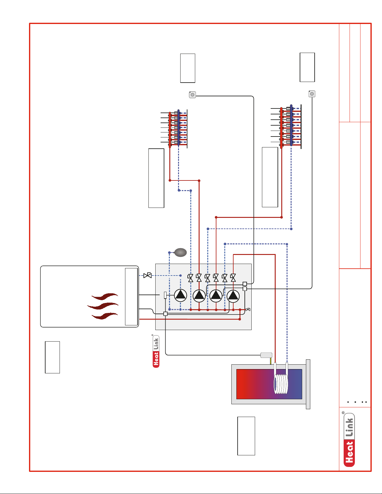
Room
Thermostat
Room
Thermostat
SCH-V100-M003
SCH-V100-E002
SCH-MRIB-R001
Schematic #:
Wiring detail see:
Rough-in wiring see:
BOILER
NOTE
All Pumps with
For Remote Manifolds.
Heating Supply & Return
Check Valves
LNG
Circ
Primary
Circ
Radiant
Circ
Radiant
DHW
Circ
For Remote Manifolds.
Heating Supply & Return
Viessmann Vitodens 100-W Boiler
V102
Panel(s):
Heat Source:
IFHWH, Radiant Heating
2014-05-09
Heat Load(s):
Date:
DHW TANK
Drawings are for HeatLink suggested system layout only! User must determine
if system layout will work for their particular application.
Air vents, expansion tanks, pressure relief valves, etc. for heat source as per
local codes.
Use isolation ball valves for all circuits and components.
Notes:
Local codes, regulations, and authorities have final jurisdiction.
1-866-661-5332
www.heatlinkgroup.com
65
Page 68
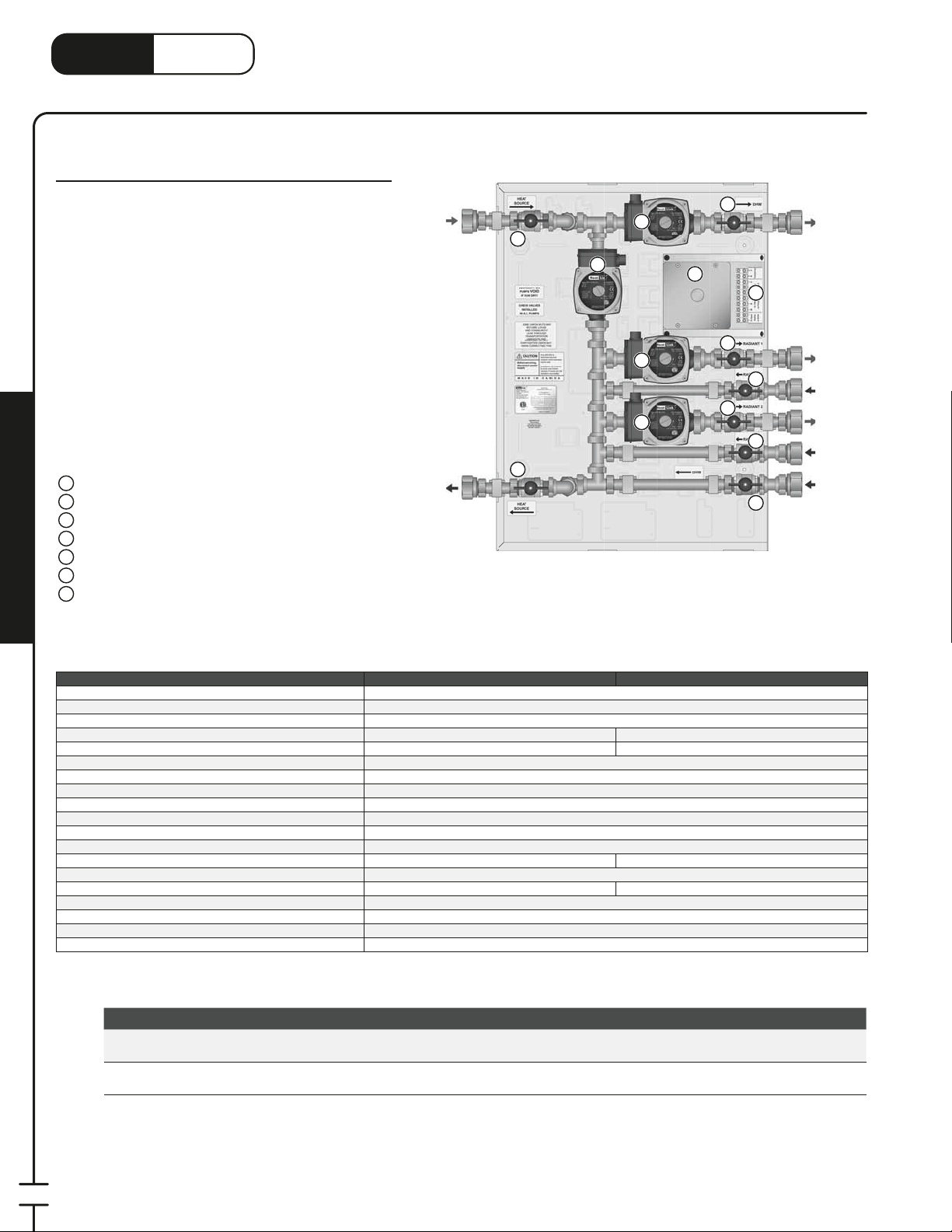
LinkHeat
1
3
www.heatlink.com
CAD Boiler Panels
CAD Series
®
CAD Boiler Panels
Canada - July 1, 2014
CAD02
These panels work with Lochinvar Cadet boilers. The dark
grey color of the enclosure is similar to the Cadet boilers.
The panel has three or four Grundfos UPS15-58 pumps.
There is a primary pump, a DHW water pump and one
or two heating pumps. The primary and DHW pumps
are controlled by the boiler. On the CAD01 model, the
heating pump is controlled by a thermostat (supplied
separately) wired to the boiler. On the CAD02 model, each
heating pump is controlled by a thermostat (supplied
separately) wired to the terminal strip on the panel. The
water temperature is controlled by the boiler.
Panel Components
1
Primary Pump
2
DHW Pump
Radiant 1 Pump
3
Radiant 2 Pump (CAD02 only)
4
Electrical Connection Box
5
24V Terminal Strip (CAD02 only)
6
Isolation Valve
7
Panel Enclosure (not shown)
;
Mechanical Room in a Box
Primary
Supply
Primary
Return
7
2
7
1
3
4
7
5
6
7
7
7
7
7
DHW
Supply
Radiant 1
Supply
Radiant 1
Return
Radiant 2
Supply
Radiant 2
Return
DHW
Return
Listing cETLus
Conforms to CAN/CSA-C22 No.14, UL508
Dimensions
Nominal panel output 80,000 btu/hr 100,000 btu/hr
Nominal ow 6.0 US gpm @ 35°F ΔT 10.0 US gpm @ 35°F ΔT
Max ambient temperature 120°F (49°C)
Min operating temperature 40°F (4°C)
Max operating temperature 200°F (93°C)
Max operating pressure 125 psi (862 kPa)
Power requirements 120 V(ac)/24 V(ac) 60 Hz
Primary pump Non-ferrous, Grundfos UPS15-58
Radiant 1 pump Non-ferrous, Grundfos UPS15-58
Radiant 2 pump n/a
DHW pump Non-ferrous, Grundfos UPS15-58
Auxiliary terminal n/a 1 dry contact, max. load 1.5A
Piping
Piping connections 1" FNPT
Backplate 16 gauge galvanized steel
Enclosure Powder coated steel
CAD01 CAD02
26-
⁄4"H × 19-1⁄2"W × 7-1⁄8"D
Non-ferrous,Grundfos UPS15-58
⁄4" 304 SS tubing
Stk# Description Pkg Qty Carton Qty Unit List Price / Unit
Sept
2014
Sept
2014
CAD01 CAD Boiler Panel 1 ea.
CAD02 CAD Boiler Panel High Capacity 1 ea.
66
Page 69
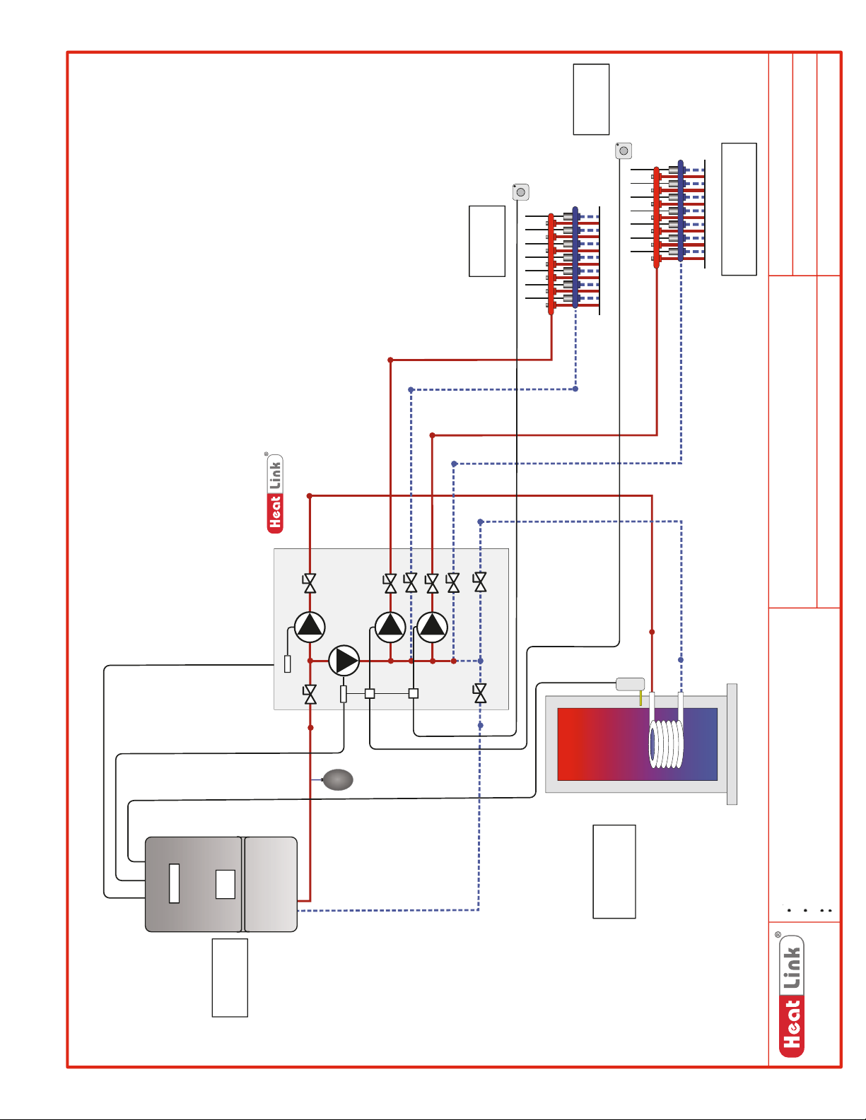
Room
Thermostat
NOTE
All Pumps with
Check Valves
Circ
DHW
Circ
Primary
Circ
Radiant
Circ
Radiant
Room
Thermostat
For Remote Manifolds.
Heating Supply & Return
SCH-CAD-M002
SCH-CAD-E002
SCH-MRIB-R001
Schematic #:
Wiring detail see:
Rough-in wiring see:
Lochinvar Cadet Boiler
CAD02
IFHWH, Radiant Heating
2014-05-23
Panel(s):
Heat Source:
Heat Load(s):
Date:
CADET
BOILER
LNG
LNG
DHW TANK
Drawings are for HeatLink suggested system layout only! User must determine
if system layout will work for their particular application.
Air vents, expansion tanks, pressure relief valves, etc. for heat source as per
local codes.
Notes:
www.heatlink.com
Use isolation ball valves for all circuits and components.
Local codes, regulations, and authorities have final jurisdiction.
1-866-661-5332
67
Page 70
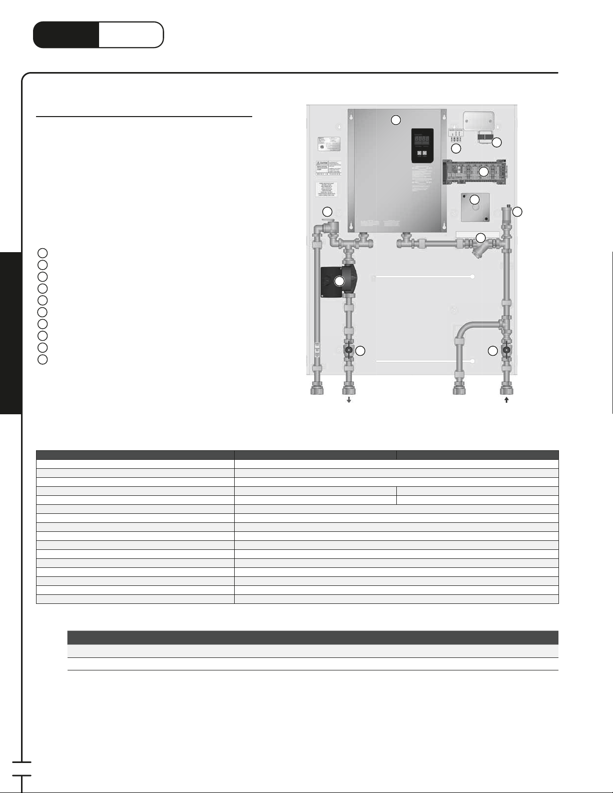
LinkHeat
1
3
www.heatlink.com
®
Electric Boiler Panels
Canada - July 1, 2014
ELBP Electric Boiler Panel
Stk# ELBP30 & ELBP50
The Electric Boiler Panel includes an 11kV or 18kV
electric boiler, automatic air vent, pressure relief valve,
strainer, pump, connection for an expansion tank, 24Vac
transformer, StatLink® 6 Zone Base Module, and electrical
box for 240V connection.
The Electric Boiler Panel’s primary application is for
heating small areas where quick plug and play installation
is needed or alternative fuel sources aren’t available.
Panel Components
1
Electric Boiler
2
Primary Pump
3
240Vac Electrical Connection Box
110Vac Terminal Strip
4
24Vac Transformer
5
StatLink® 6 Zone Base Module
6
Strainer
7
Automatic Air Vent
8
Pressure Relief Valve
9
Isolation Valve
10
Panel Enclosure (not shown)
;
ELBP30
1
4
9
2
10 10
5
6
3
8
7
Mechanical Room in a Box
Listing cETLus
Conforms to CAN/CSA-C22 No.14, UL508
Dimensions 37Nominal panel output 30,000 btu/hr 50,000 btu/hr
Nominal ow 3.0 US gpm @ 35°F ΔT 5.0 US gpm @ 35°F ΔT
Max ambient temperature 120°F (49°C)
Min operating temperature 40°F (4°C)
Max operating temperature 200°F (93°C)
Max operating pressure 125 psi (862 kPa)
Power requirements 120 V(ac) / 240 V(ac) 60 Hz
Primary pump Non-ferrous, Grundfos UPS15-58
Auxiliary terminal 1 dry contact, max. load 8A
Piping
Piping connections 1" FNPT
Backplate
Enclosure Powder coated steel
Stk# Description Pkg Qty Carton Qty Unit List Price / Unit
ELBP30 Electric Boiler Panel 30,000BTU 1 ea.
New!
ELBP50 Electric Boiler Panel 50,000BTU 1 ea.
Pressure
Relief
ELBP30 ELBP50
Primary
Supply
⁄2"H × 29-1⁄4"W × 4-3⁄4"D
⁄4" 304 SS tubing
16 gauge galvanized steel
Expansion
Tank
Primary
Return
68
Page 71
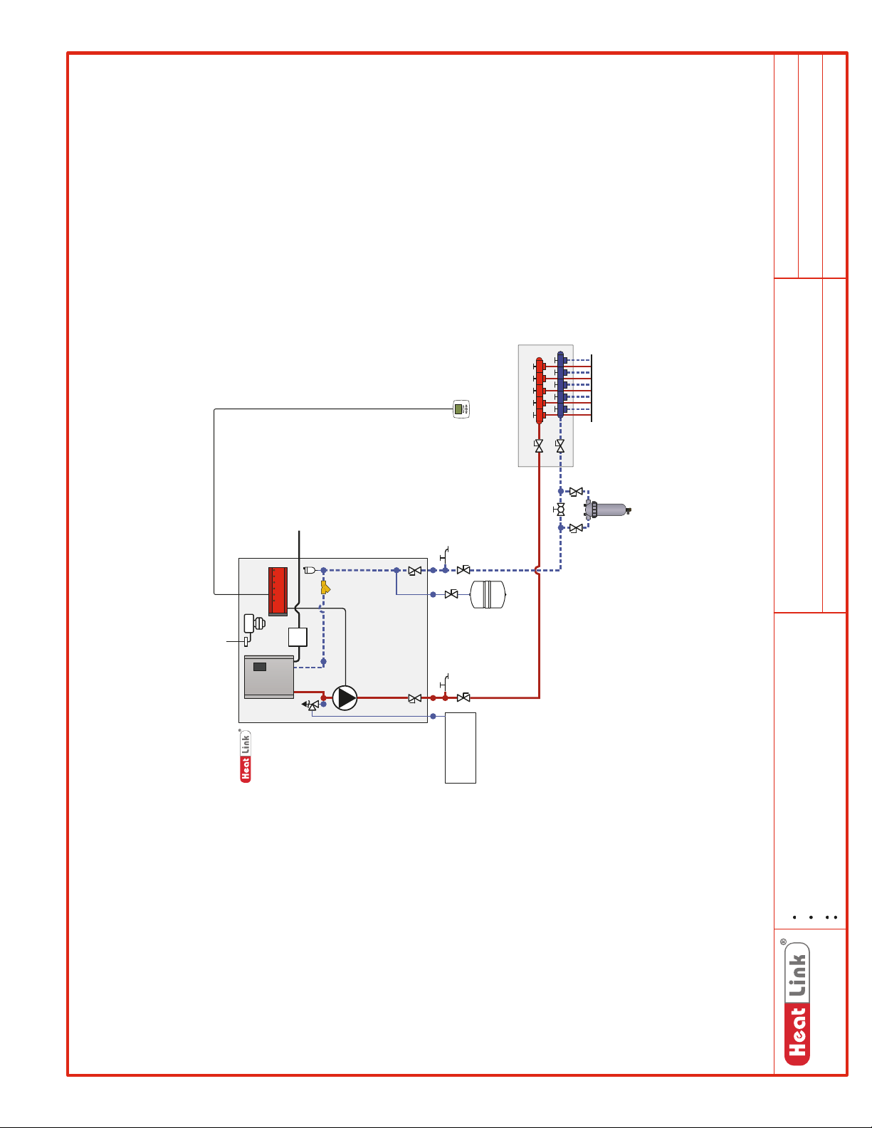
Thermostat
Manifold
Radiant Heating
SCH-ELBP-M001
SCH-MRIB-R001
SCH-ELBP-E001
Schematic #:
Wiring detail see:
Rough-in wiring see:
120Vac
Panel
ELBP30/50
240Vac
relief pipe to
Extend pressure
within 6" of floor.
Recommended
Sidestream Filter
Electric Boiler
ELBP30, ELBP50
Panel(s):
Heat Source:
Drawings are for HeatLink suggested system layout only! User must determine
if system layout will work for their particular application.
Air vents, expansion tanks, pressure relief valves, etc. for heat source as per
Notes:
Radiant Heating – Single Zone
2014-05-15
Heat Load(s):
Date:
local codes.
Use isolation ball valves for all circuits and components.
Local codes, regulations, and authorities have final jurisdiction.
1-866-661-5332
www.heatlink.com
69
Page 72
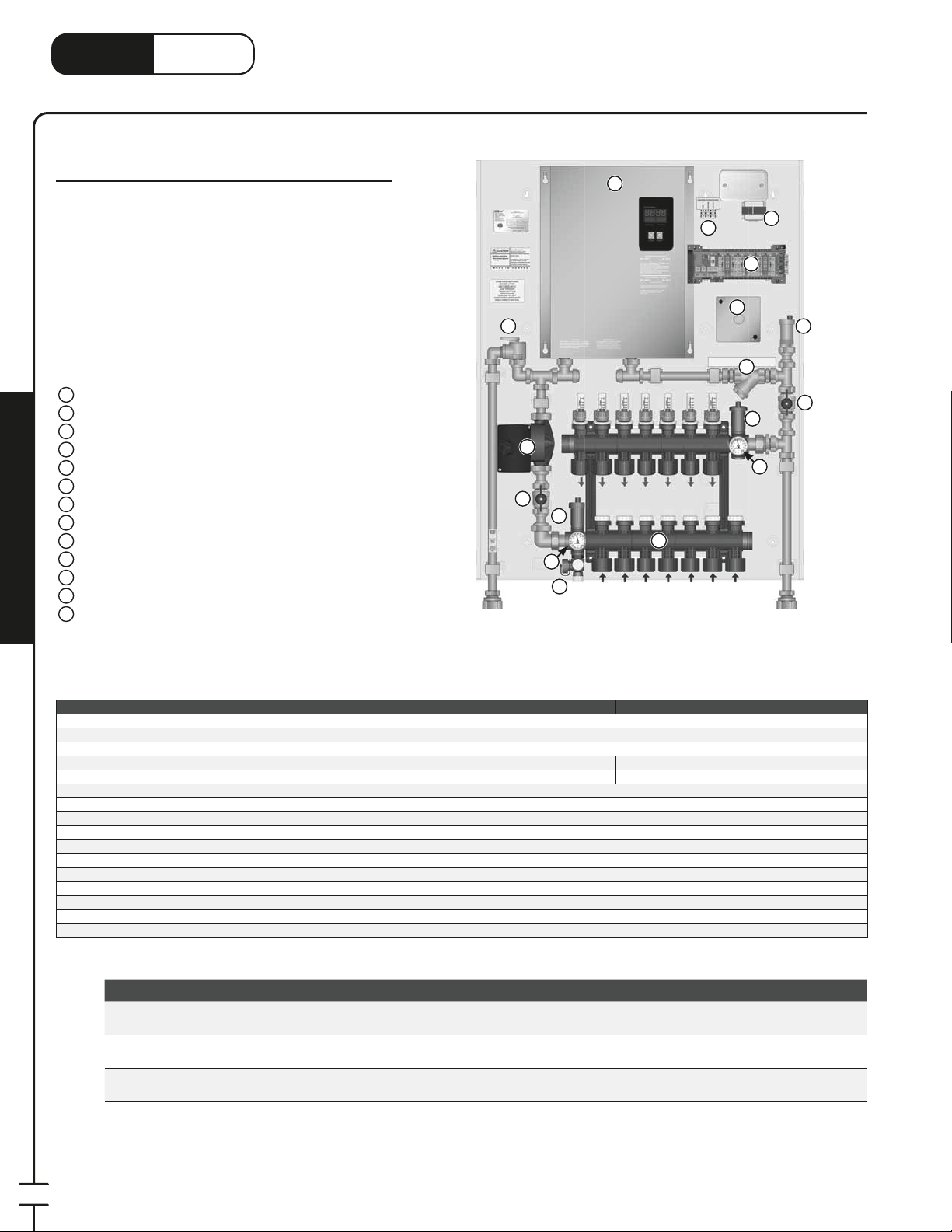
LinkHeat
1
3
www.heatlink.com
®
Electric Boiler Panels with Manifold
Canada - July 1, 2014
ELBP Electric Boiler Panel with Manifold
Stk# ELBP30TS3, ELBP30TS5, & ELBP50TS7
The Electric Boiler Panel includes an 11kV or 18kV electric
boiler, automatic air vent, pressure relief valve, strainer,
pump, connection for an expansion tank, TwistSeal®
Multiport Mini Manifold, 24Vac transformer, StatLink®
6 Zone Base Module, and electrical box for 240V
connection.
The Electric Boiler Panel’s primary application is for
heating small areas where quick plug and play installation
is needed or alternative fuel sources aren’t available.
Panel Components
Electric Boiler
1
Primary Pump
2
240Vac Electrical Connection Box
3
110Vac Terminal Strip
4
24Vac Transformer
5
StatLink® 6 Zone Base Module
6
Strainer
7
Automatic Air Vent
8
Pressure Relief Valve
9
Isolation Valve
10
TwistSeal® Mini Multiport Manifold
11
Thermometer
12
Hosebib
13
Mechanical Room in a Box
Panel Enclosure (not shown)
;
ELBP50TS7
Pressure
Relief
1
4
9
2
10
8
11
12
13
5
6
3
8
7
10
8
12
Expansion
Tank
Listing cETLus
Conforms to CAN/CSA-C22 No.14, UL508
Dimensions
Nominal panel output 30,000 btu/hr 50,000 btu/hr
Nominal ow 3.0 US gpm @ 35°F ΔT 5.0 US gpm @ 35°F ΔT
Max ambient temperature 120°F (49°C)
Min operating temperature 40°F (4°C)
Max operating temperature 200°F (93°C)
Max operating pressure 125 psi (862 kPa)
Power requirements 120 V(ac) / 240 V(ac) 60 Hz
Primary pump Non-ferrous, Grundfos UPS15-58
Auxiliary terminal 1 dry contact, max. load 8A
Piping
Piping connections 1" FNPT
Backplate 16 Gauge galvanized steel
Enclosure Powder coated steel
ELBP30TS3, ELBP30TS5 ELBP50TS7
37-
⁄2"H × 29-1⁄4"W × 4-3⁄4"D
⁄4" 304 SS tubing
Stk# Description Pkg Qty Carton Qty Unit List Price / Unit
New!
New!
ELBP30TS3
ELBP30TS5
ELBP50TS7
Electric Boiler Panel 30,000BTU with 3 Loop Twist Seal Mini
Multiport
Electric Boiler Panel 30,000BTU with 5 Loop Twist Seal Mini
Multiport
Electric Boiler Panel 50,000BTU with 7 Loop Twist Seal Mini
Multiport
1 ea.
1 ea.
1 ea.
70
Page 73
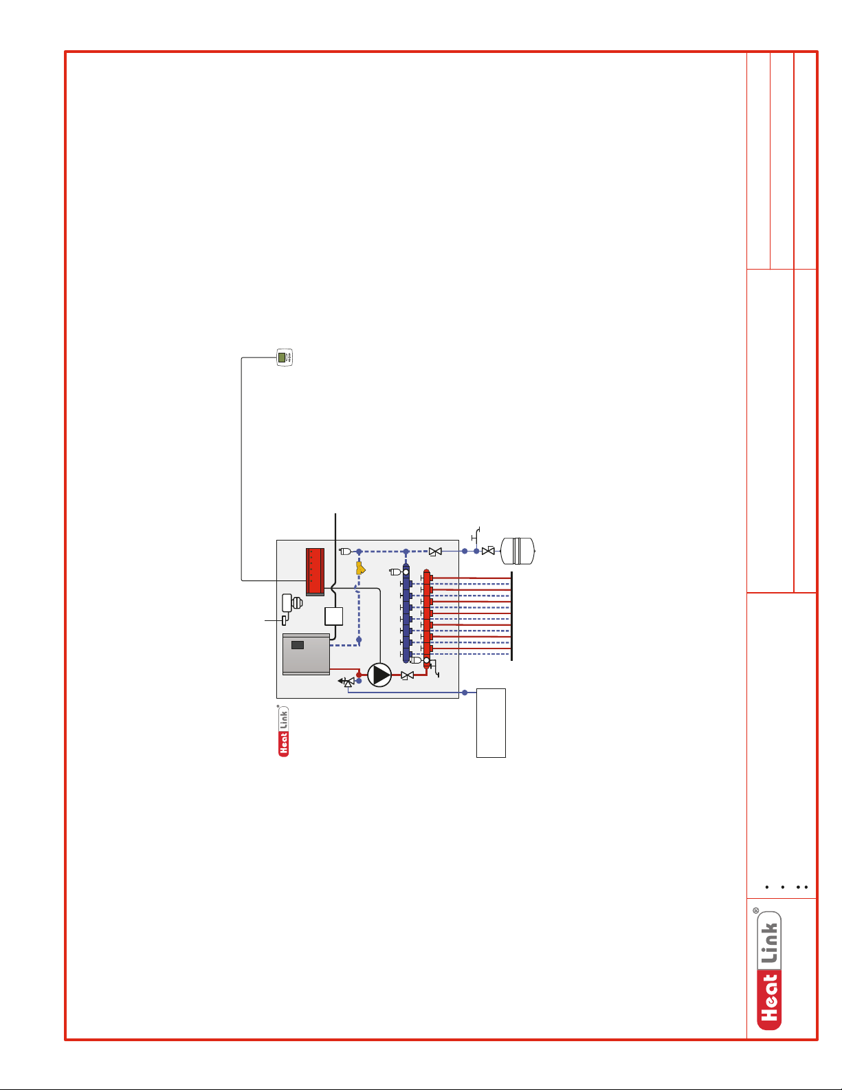
Thermostat
SCH-ELBP-M002
SCH-MRIB-R001
SCH-ELBP-E001
Schematic #:
Wiring detail see:
Rough-in wiring see:
120Vac
Panel
ELBP50TS7
240Vac
relief pipe to
Extend pressure
within 6" of floor.
Electric Boiler
ELBP30TS3, ELBP30TS5, ELBP50TS7
Radiant Heating – Single Zone
Panel(s):
Heat Source:
Heat Load(s):
Drawings are for HeatLink suggested system layout only! User must determine
if system layout will work for their particular application.
Air vents, expansion tanks, pressure relief valves, etc. for heat source as per
local codes.
Notes:
2014-05-15
Date:
Use isolation ball valves for all circuits and components.
Local codes, regulations, and authorities have final jurisdiction.
1-866-661-5332
www.heatlink.com
71
Page 74
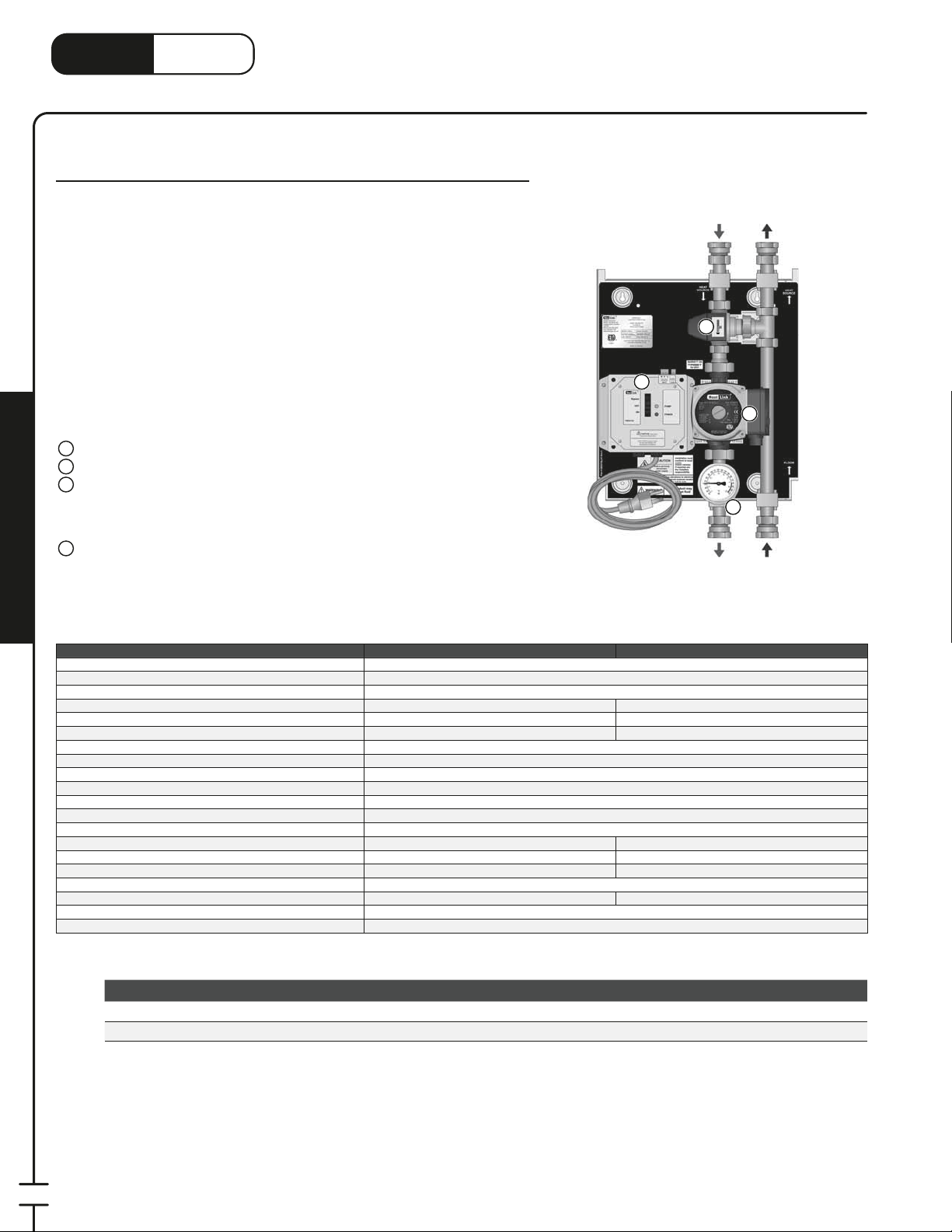
®
3
3
3
3
LinkHeat
www.heatlink.com
TMP 40/70 MBH 3-Way Mixing Panels
Stk# TMP040 & TMP070
TMP – 3-Way Mixing Panels
Canada - July 1, 2014
The TMP 3-Way Mixing Panel’s primary application is as a single zone mixing
device where there are no ow requirements in the primary loop. Intended to
Primary
Supply
be used with DHW tanks as a heat source, the pump is activated once every 24
hours, for 15 minutes, to ensure that potable water in the piping is not stagnant.
At this time, a DHW priority option for these panels is not available.
TMP040
These panels can also be used as subpanels to provide additional mixed
temperature loops.
When the panel receives a call for heat, the pump is activated, and the
2
thermostatic control head in the 3-way mixing valve will automatically regulate
the water temperature in the secondary circuit. When not used with a DHW tank
as a heat source, secondary zoning downstream of the panel is possible.
3
Panel Components
Pump
1
3-Way Thermostatic Mixing Valve
2
Power Box with 6' Power Cord
3
• 24hr Timer for Potable Applications
• Auxiliary Dry Contacts for Heat Source
• Bypass Function
Thermometer
4
Panel Enclosure (not shown)
;
Secondary
Supply
Mechanical Room in a Box
Listing cETLus
Conforms to CAN/CSA-C22 No.14, UL508
Dimensions 14Weight 15 lbs. 17 lbs.
Nominal panel output 40,000 Btu/hr 70,000 Btu/hr
Nominal ow 4.0 US gpm @ 20°F ΔT 7.0 US gpm @ 20°F ΔT
Nominal pressure drop outside of panel 4 ft
Max ambient temperature 120°F
Max water temperature 200°F
Min required ow for correct temp control 1 US gpm
Power supply: pre-wired on system controller 110 V(ac); max. current 1A
Pump Non-ferrous, Grundfos UPS15-58
Auxiliary terminal 1 dry contact, max. load 1.5A
Temperature control method
Temperature control range 110-140°F 110-140°F
Mix Valve Cv 1.8 3.7
Piping
Piping connections
Backplate 16 gauge galvanized steel
Enclosure Powder coated steel
TMP040 TMP070
⁄4"H × 12-1⁄2"W × 6-1⁄2"D
⁄4" 3-Way thermostatic 1" 3-Way thermostatic
⁄4" FNPT 1" FNPT
⁄4" 304 SS tubing
4
Primary
Return
1
Secondary
Return
72
Stk# Description Pkg Qty Carton Qty Unit List Price / Unit
TMP040 TMP 40MBH 3-way Mixing Panel 1 ea.
TMP070 TMP 70MBH 3-way Mixing Panel 1 ea.
Page 75
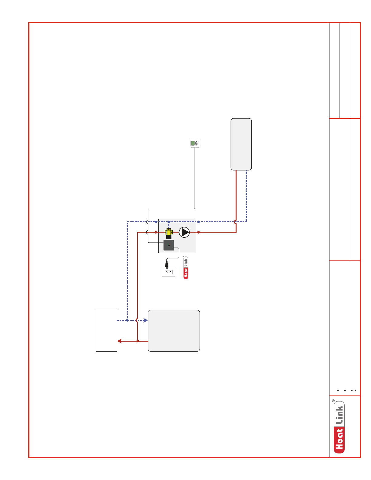
Thermostat
Heating Load
SCH-TMP-M001
SCH-MRIB-R001
SCH-TMP-E001
Schematic #:
Wiring detail see:
Rough-in wiring see:
Generic
TMP Series
Generic – Single Zone
2013-05-21
Panel(s):
Heat Source:
Heat Load(s):
Date:
DHWtoandfrom
House
Heat
Source
Panel
TMP040/070
Drawings are for HeatLink suggested system layout only! User must determine
if system layout will work for their particular application.
Air vents, expansion tanks, pressure relief valves, etc. for heat source as per
local codes.
Use isolation ball valves for all circuits and components.
Notes:
Local codes, regulations, and authorities have final jurisdiction.
1-866-661-5332
www.heatlinkgroup.com
73
Page 76
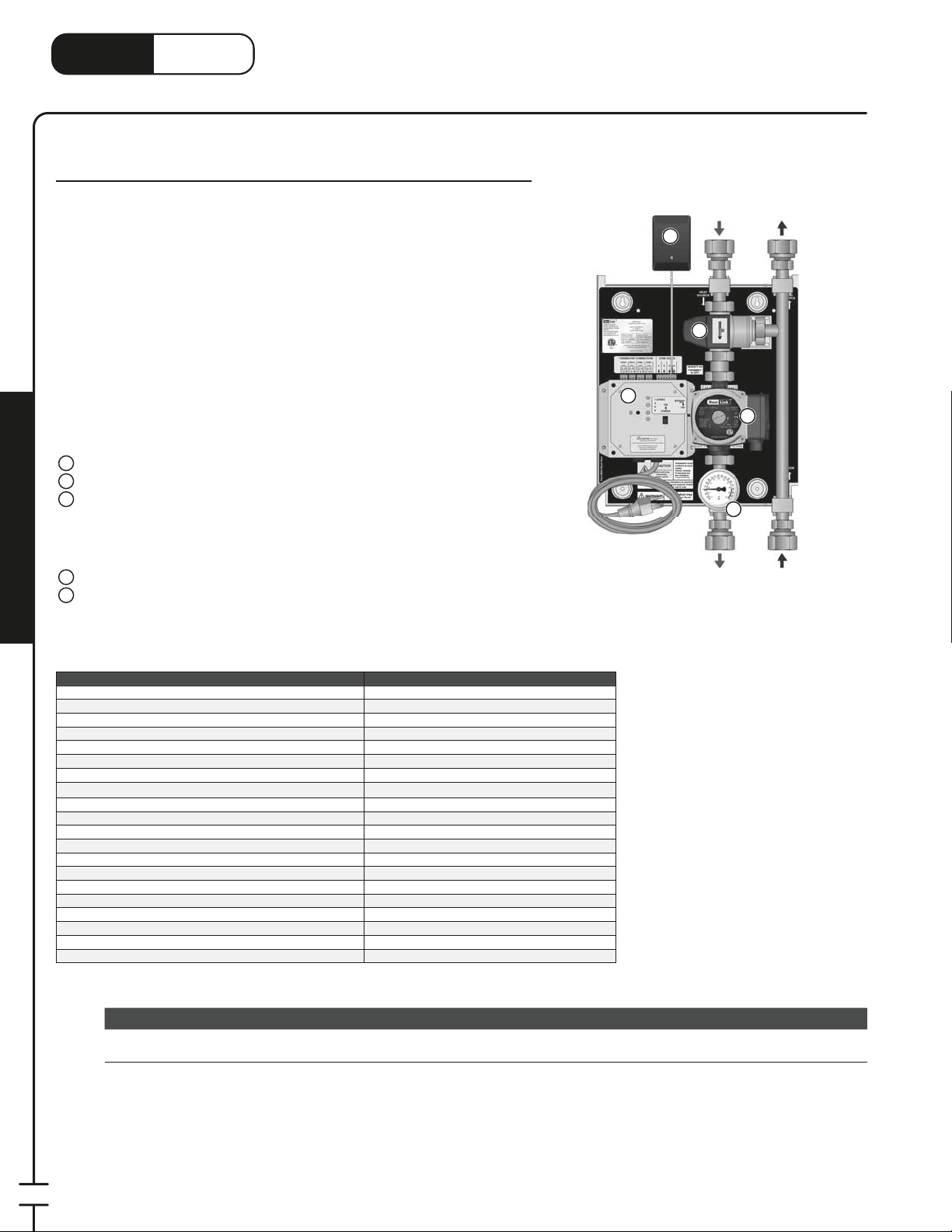
®
3
3
LinkHeat
www.heatlink.com
TMP 70 MBH 3-Way Mixing Panel with Zoning
Stk# TMP070Z
TMP – 3-Way Mixing Panel with Zoning
Canada - July 1, 2014
The TMP 3-Way Mixing Panel’s primary application is as a multizone mixing
device where there are no ow requirements in the primary loop. Intended to
be used with DHW tanks as a heat source, the pump is activated, and actuators
(sold separately) are opened once every 24 hours, for 15 minutes, to ensure that
potable water in the piping is not stagnant. The power box has thermostat inputs
and actuator outputs for up to four zones (two actuators per zone). At this time, a
DHW priority option for this panel is not available.
When the panel receives a call for heat, the pump is activated, and the
thermostatic control head in the 3-way mixing valve will automatically regulate
the water temperature in the secondary circuit. When used with a DHW tank as
a heat source, secondary zoning downstream of the panel is possible (subject to
local codes).
Panel Components
1
Pump
2
3-Way Thermostatic Mixing Valve
3
Power Box with 6' Power Cord
• 24hr Timer for Potable Applications
• Auxiliary Dry Contacts for Heat Source
• Thermostat Inputs and Actuator Outputs for 4 Zones
• Bypass Function
4
24Vac Plug-in Transformer
5
Thermometer
Panel Enclosure (not shown)
;
Mechanical Room in a Box
Primary
Supply
4
2
3
Secondary
Supply
5
Primary
Return
1
Secondary
Return
Listing cETLus
Conforms to CAN/CSA-C22 No.14, UL508
Dimensions 14Weight 17 lbs.
Nominal panel output 70,000 Btu/hr
Nominal ow 7.0 US gpm @ 20°F ΔT
Nominal pressure drop outside of panel 4 ft
Max ambient temperature 120°F
Max water temperature 200°F
Min required ow for correct temp control 1 US gpm
Power supply: pre-wired on system controller 110 V(ac); max. current 2A
Pump Non-ferrous, Grundfos UPS15-58
Auxiliary terminal 1 dry contact, max. load 1.5A
Temperature control method 1" 3-Way thermostatic
Temperature control range 110-140°F
Mix Valve Cv 3.7
Piping
Piping connections 1" FNPT
Backplate 16 gauge galvanized steel
Enclosure Powder coated steel
Stk# Description Pkg Qty Carton Qty Unit List Price / Unit
Special
Order*
TMP070Z TMP 70MBH 3-way Mixing Panel with Zoning 1 ea.
TMP070Z
⁄4"H × 12-1⁄2"W × 6-1⁄2"D
⁄4" 304 SS tubing
74
* Lead time may vary. Call to con rm time line.
Page 77
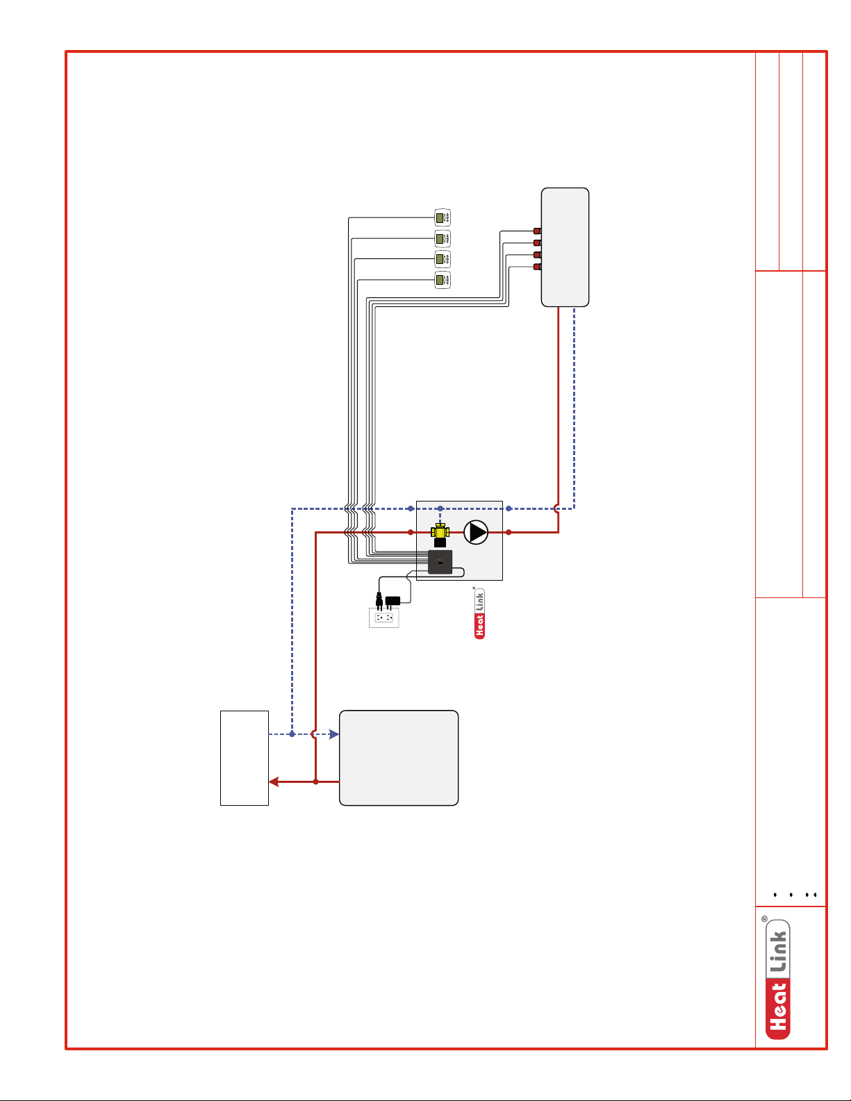
Heating Load
Up to 4 Zones
SCH-TMPZ-M001
SCH-MRIB-R006
SCH-TMPZ-E001
Schematic #:
Wiring detail see:
Rough-in wiring see:
Generic
TMP070Z
Generic – Up to 4 Zones
2013-05-23
Panel(s):
Heat Source:
Heat Load(s):
Date:
Panel
TMP070Z
House
DHW to and from
Heat
Source
Drawings are for HeatLink suggested system layout only! User must determine
if system layout will work for their particular application.
Air vents, expansion tanks, pressure relief valves, etc. for heat source as per
local codes.
Use isolation ball valves for all circuits and components.
Notes:
Local codes, regulations, and authorities have final jurisdiction.
1-866-661-5332
www.heatlinkgroup.com
75
Page 78
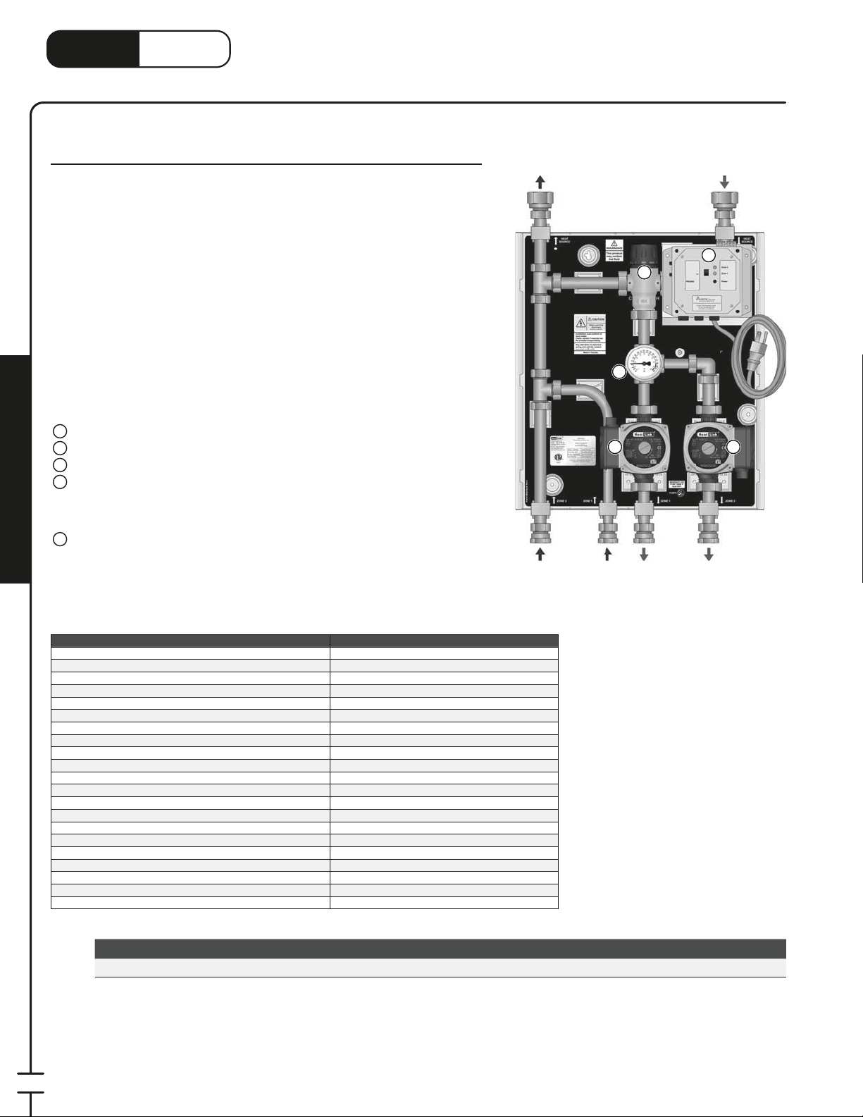
®
1
3
3
LinkHeat
www.heatlink.com
TMP 85 MBH Dual Pump Mixing Panel
Stk# TMP085DP
The TMP 3-Way Mixing Panel’s primary application is as a single zone mixing
device where there are no ow requirements in the primary loop. Intended to be
used with DHW tanks as a heat source, the pump is activated once every 24 hours,
for 15 minutes, to ensure that potable water in the piping is not stagnant. At this
time, a DHW priority option for this panel is not available.
These panels can also be used as subpanels to provide additional mixed
temperature loops.
When the panel receives a call for heat, the pump is activated, and the
thermostatic control head in the 3-way mixing valve will automatically regulate
the water temperature in the secondary circuit. When not used with a DHW tank
as a heat source, secondary zoning downstream of the panel is possible. The
TMP085DP not only allows for higher output, but it is also a 2-zone panel. So
even with a DHW heat source, you can now have two radiant oor zones.
Panel Components
1
Zone 1 Pump with Check Valve
2
Zone 2 Pump with Check Valve
3
3-Way Thermostatic Mixing Valve
4
Power Box with 6' Power Cord
• 24hr Timer for Potable Applications
• Bypass Function
• Auxiliary Dry Contacts for Heat Source
5
Thermometer
Panel Enclosure (not shown)
;
Mechanical Room in a Box
TMP – Dual Pump 3-Way Mixing Panel
Canada - July 1, 2014
Primary
Return
Zone 2
Return
3
5
1 2
Zone 1
Return
Zone 1
Supply
Primary
Supply
4
Zone 2
Supply
Listing cETLus
Conforms to CAN/CSA-C22 No.14, UL508
Dimensions 18Weight 30 lbs.
Nominal panel output 85,000 Btu/hr
Nominal ow 2× 4.25 US gpm @ 20°F ΔT
Nominal pressure drop outside of panel 4 ft
Max ambient temperature 120°F
Max water temperature 200°F
Min required ow for correct temp control 1 US gpm
Power supply: pre-wired on system controller 110 V(ac); max. current 2A
Zone 1 pump Non-ferrous, Grundfos UPS15-58
Zone 2 pump Non-ferrous, Grundfos UPS15-58
Auxiliary terminal 1 dry contact, max. load 1.5A
Temperature control method 1" 3-Way thermostatic
Temperature control range 110-140°F
Mix Valve Cv 3.0
Piping
Piping connections 1" FNPT primary,
Backplate 16 gauge galvanized steel
Enclosure Powder coated steel
Stk# Description Pkg Qty Carton Qty Unit List Price / Unit
TMP085DP TMP 85MBH Dual Pump 3-way Mixing panel 1 ea.
TMP085DP
⁄4"H × 16-1⁄4"W × 7-3⁄4"D
⁄4" 304 SS tubing
⁄4" FNPT secondary
76
Page 79
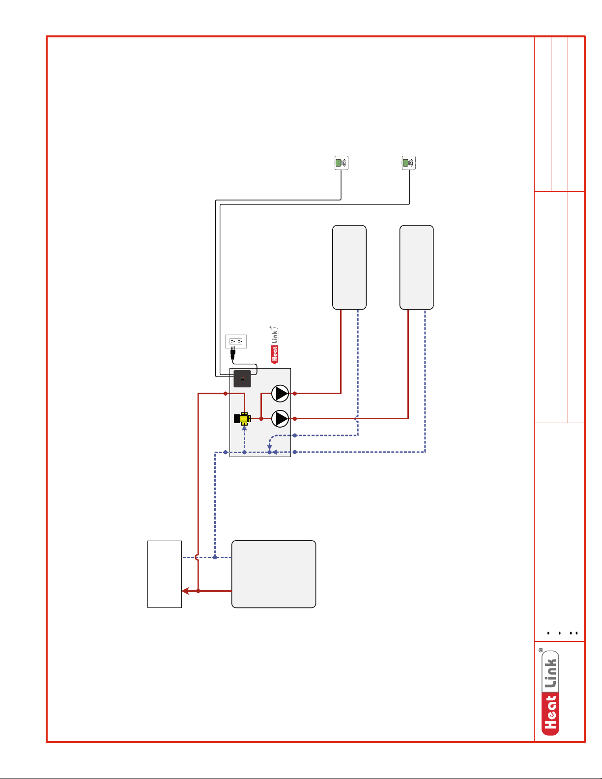
SCH-TMPDP-M001
SCH-MRIB-R001
SCH-TMPD-E001
Schematic #:
Wiring detail see:
Zone 2 Thermostat
Zone 1 Thermostat
Rough-in wiring see:
Heating Zone 2
Panel
TMP085DP
Check Valve in
Both Pumps
House
DHW to and from
Heat
Source
Heating Zone 1
Generic
Heat Source:
TMP085DP
Panel(s):
Generic – Dual Zones
Heat Load(s):
2013-05-21
Date:
Drawings are for HeatLink suggested system layout only! User must determine
if system layout will work for their particular application.
Air vents, expansion tanks, pressure relief valves, etc. for heat source as per
local codes.
Use isolation ball valves for all circuits and components.
Notes:
Local codes, regulations, and authorities have final jurisdiction.
1-866-661-5332
www.heatlinkgroup.com
77
Page 80
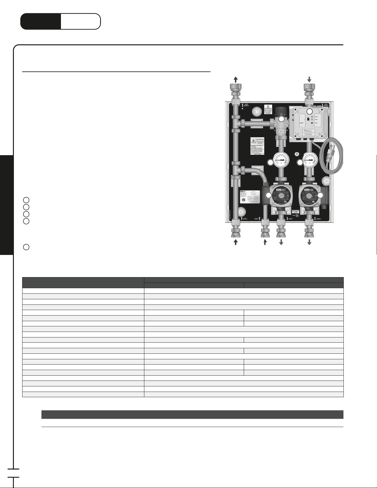
®
1
3
3
LinkHeat
TMP – 2-Temperature 3-Way Mixing Panel
www.heatlink.com
TMP 200 MBH 2-Temperature Mixing Panel
Stk# TMP200DT
The TMP 3-Way Mixing Panel’s primary application is as a single zone mixing
device where there are no ow requirements in the primary loop. Intended to be
used with DHW tanks as a heat source, the pump is activated once every 24 hours,
for 15 minutes, to ensure that potable water in the piping is not stagnant. At this
time, a DHW priority option for this panel is not available.
These panels can also be used as subpanels to provide additional mixed
temperature loops.
When the panel receives a call for heat, the pump is activated, and the
thermostatic control head in the 3-way mixing valve will automatically regulate
the water temperature in the secondary circuit. When not used with a DHW
tank as a heat source, secondary zoning downstream of the panel is possible.
The TMP200DT is a dual temperature panel. The low temperature output is the
same as the TMP070, but it also has a high temperature pump, for secondary high
temperature applications such as a fan coil or baseboard.
Primary
Return
Canada - July 1, 2014
Primary
Supply
4
3
5 5
Panel Components
1
Mixed Temp Pump with Check Valve
2
High Temp Pump with Check Valve
3
3-Way Thermostatic Mixing Valve
4
Power Box with 6' Power Cord
1 2
• 24hr Timer for Potable Applications
• Bypass Function
• Auxiliary Dry Contacts for Heat Source
Mechanical Room in a Box
Thermometer
5
Panel Enclosure (not shown)
;
Listing cETLus
Conforms to CAN/CSA-C22 No.14, UL508
Dimensions 18Weight 30.5 lbs.
Nominal panel output 70,000 Btu/hr 130,000 Btu/hr
Nominal ow 7.0 US gpm @ 20°F ΔT 10.0 US gpm @ 26°F ΔT
Nominal pressure drop outside of panel 4 ft 8 ft
Max ambient temperature 120°F
Max water temperature 200°F
Min required ow for correct temp control 1 US gpm n/a
Power supply: pre-wired on system controller 110 V(ac); max. current 2A
Pump Non-ferrous, Grundfos UPS15-58 Non-ferrous, Grundfos UPS15-58
Auxiliary terminal 1 dry contact, max. load 1.5A
Temperature control method 1" 3-Way thermostatic None
Temperature control range 110-140°F n/a
Mix Valve Cv 3.0 n/a
Piping
Piping connections 1" FNPT primary,
Backplate 16 gauge galvanized steel
Enclosure Powder coated steel
Mixed Temp High Temp
Mixed
Temp
Return
TMP200DT
⁄4"H × 16-1⁄4"W × 7-3⁄4"D
⁄4" 304 SS tubing
High
Temp
Return
⁄4" FNPT secondary
Mixed
Temp
Supply
High
Temp
Supply
78
Stk# Description Pkg Qty Carton Qty Unit List Price / Unit
TMP200DT TMP 200MBH 2-Temperature 3-way Mixing Panel 1 ea.
Page 81
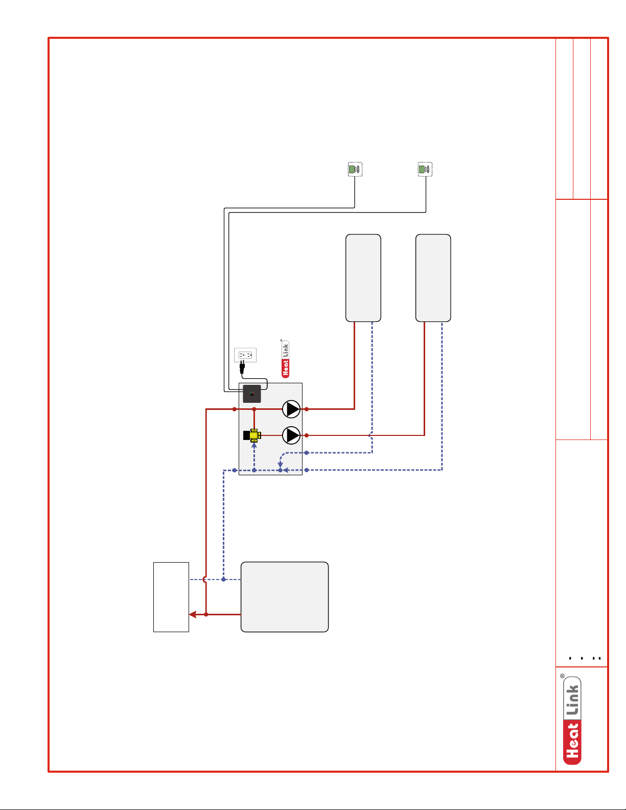
SCH-TMPDT-M001
SCH-MRIB-R001
SCH-TMPD-E001
Schematic #:
Wiring detail see:
Zone 2 Thermostat
Zone 1 Thermostat
Rough-in wiring see:
Heating Zone 2
Panel
TMP200DT
Check Valve in
Both Pumps
House
DHW to and from
Heat
Source
Heating Zone 1
Generic
TMP200DT
Generic – Dual Zones
2013-05-22
Panel(s):
Heat Source:
Heat Load(s):
Date:
Drawings are for HeatLink suggested system layout only! User must determine
if system layout will work for their particular application.
Air vents, expansion tanks, pressure relief valves, etc. for heat source as per
local codes.
Use isolation ball valves for all circuits and components.
Notes:
Local codes, regulations, and authorities have final jurisdiction.
1-866-661-5332
www.heatlinkgroup.com
79
Page 82
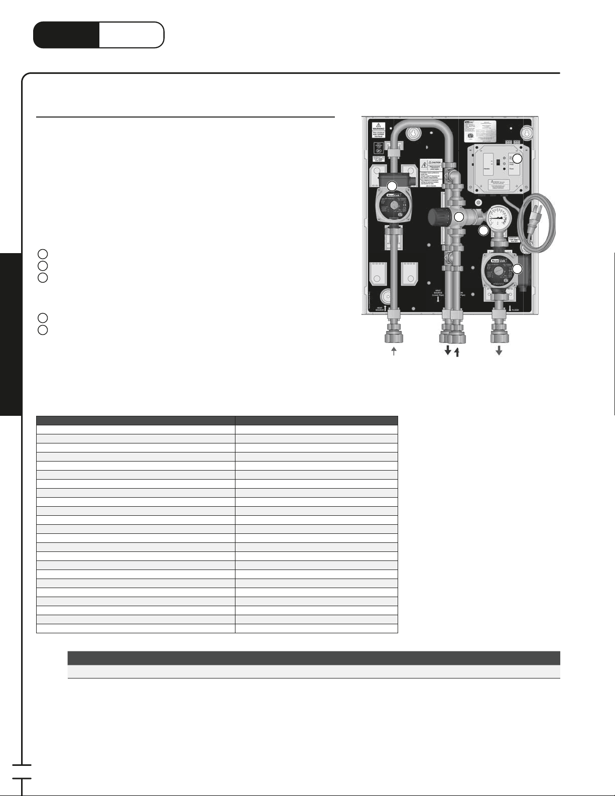
®
1
3
LinkHeat
www.heatlink.com
TWH 70 MBH Tankless Water Heater Mixing Panel
Stk# TWH070
The TWH Tankless Water Heater Mixing Panel’s primary application is as a single
zone mixing device for tankless DHW heaters. Both the primary and secondary
pumps are activated once every 24 hours, for 15 minutes, to ensure that
potable water in the piping is not stagnant.
When the panel receives a call for heat, both pumps are activated, and the
thermostatic control head in the 3-way mixing valve will automatically regulate
the water temperature in the secondary circuit. DHW priority is not available on
this model.
Panel Components
1
Primary Pump with Check Valve
2
Secondary Pump
3
Power Box with 6' Power Cord
• 24hr Timer for Potable Applications
• Bypass Function
• Auxiliary Dry Contacts for Heat Source
4
3-Way Thermostatic Mixing Valve
5
Thermometer
Panel Enclosure (not shown)
;
TWH – Tankless Water Heater Panel
Canada - July 1, 2014
3
1
4
5
2
Mechanical Room in a Box
Listing cETLus
Conforms to CAN/CSA-C22 No.14, UL508
Dimensions 18Weight 28.5 lbs.
Nominal panel output 70,000 btu/hr
Primary nominal ow 4.0 US gpm @ 35°F ΔT
Primary nominal pressure drop outside of panel 14 ft
Secondary nominal ow 7 US gpm @ 20°F ΔT
Secondary nominal pressure drop outside of panel 4 ft
Max ambient temperature 120°F
Max water temperature 200°F
Min required ow for correct temp control 1 US gpm
Power supply: pre-wired on system controller 110 V(ac); max. current 2A
Primary pump Non-ferrous, Grundfos UPS15-58
Secondary pump Non-ferrous, Grundfos UPS15-58
Auxiliary terminal 1 dry contact, max. load 1.5A
Temperature control method 1" 3-Way thermostatic
Temperature control range 100°F - 145°F
Mix Valve Cv 3.0
Piping
Piping connections 1" FNPT
Backplate 16 gauge galvanized steel
Enclosure Powder coated steel
TWH070
⁄4"H × 16-1⁄4"W × 7-3⁄4"D
⁄4" 304 SS tubing
Primary
Supply
Primary
Return
(lower pipe)
Secondary
Return
(upper pipe)
Secondary
Supply
80
Stk# Description Pkg Qty Carton Qty Unit List Price / Unit
TWH070 TWH 70MBH Tankless Water Heater Mixing Panel 1 ea.
Page 83
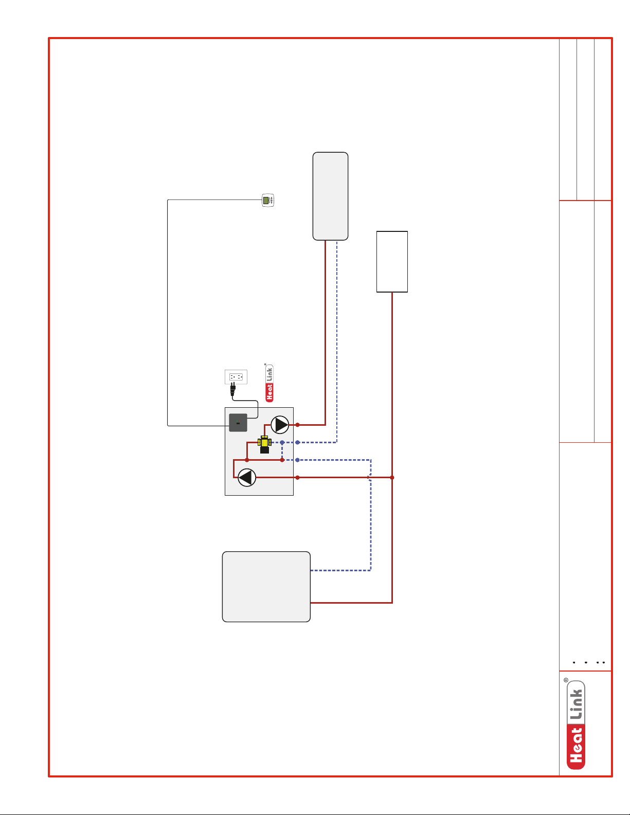
SCH-MRIB-R001
SCH-TWH-E001
Schematic #:
Wiring detail see:
Rough-in wiring see:
Check
Valve in
Pump
Primary
Thermostat
Panel
TWH070
Heating Load
to House
DHW Supply
Generic
TWH070
Panel(s):
Heat Source:
Generic – Single Zone
2013-03-18
Heat Load(s):
Date:
Heat
Source
Drawings are for HeatLink suggested system layout only! User must determine
if system layout will work for their particular application.
Air vents, expansion tanks, pressure relief valves, etc. for heat source as per
local codes.
Notes:
www.heatlink.com
Use isolation ball valves for all circuits and components.
Local codes, regulations, and authorities have final jurisdiction.
1-866-661-5332
81
Page 84
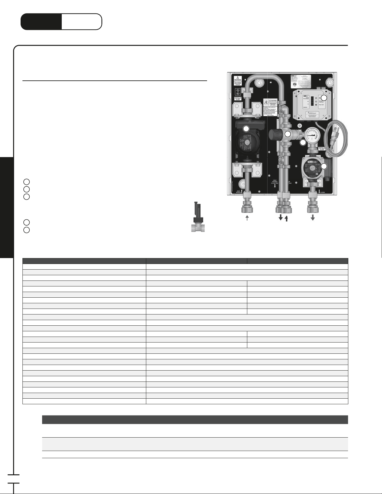
®
1
3
1
LinkHeat
TWH – Tankless Water Heater Panels with Optional DHW Priority
www.heatlink.com
TWH 70 MBH Tankless Water Heater Mixing Panels with Optional
DHW Priority
Stk# TWH070P & TWH070XP
The TWH Tankless Water Heater Mixing Panel’s primary application is as a single
zone mixing device for tankless DHW heaters. Both the primary and secondary
pumps are activated once every 24 hours, for 15 minutes, to ensure that
potable water in the piping is not stagnant.
When the panel receives a call for heat, both pumps are activated, and the
thermostatic control head in the 3-way mixing valve will automatically regulate
the water temperature in the secondary circuit. The TWH070XP is designed
for applications where there is an extremely high ow resistance in the heat
source. Both the TWH070P and the TWH070XP are compatible with the
optional ow switch (FLWSWTCH) that turns o the primary pump when there
is ow in the regular DHW line.
Panel Components
1
Primary Pump with Check Valve
2
Secondary Pump
3
Power Box with 6' Power Cord
• 24hr Timer for Potable Applications
• Bypass Function
• Auxiliary Dry Contacts for Heat Source
4
3-Way Thermostatic Mixing Valve
Thermometer
5
Panel Enclosure (not shown)
;
FLWSWTCH
TWH070XP
Primary
Supply
1
Primary
Return
(lower pipe)
Canada - July 1, 2014
3
4
5
2
Secondary
Return
(upper pipe)
Secondary
Supply
Mechanical Room in a Box
Listing cETLus
Conforms to CAN/CSA-C22 No.14, UL508
Dimensions 18Weight 32.5 lbs. 39 lbs.
Nominal panel output 70,000 btu/hr 70,000 btu/hr
Primary nominal ow 4.0 US gpm @ 35°F ΔT 4.0 US gpm @ 35°F ΔT
Primary nominal pressure drop outside of panel 14 ft 24 ft
Secondary nominal ow 7 US gpm @ 20°F ΔT 7 US gpm @ 20°F ΔT
Secondary nominal pressure drop outside of panel 4 ft 4 ft
Max ambient temperature 120°F
Max water temperature 200°F
Min required ow for correct temp control 1 US gpm
Power supply: pre-wired on system controller 110 V(ac); max. current 2A 110 V(ac); max. current 3A
Primary pump Non-ferrous, Grundfos UPS15-58
Secondary pump Non-ferrous, Grundfos UPS15-58
Auxiliary terminal 1 dry contact, max. load 1.5A
DHW priority Optional @ ~0.5 US gpm DHW ow
Temperature control method 1" 3-Way thermostatic
Temperature control range 100°F - 145°F
Mix Valve Cv 3.0
Piping
Piping connections 1" FNPT
DHW priority switch connection
Backplate 16 gauge galvanized steel
Enclosure Powder coated steel
Stk# Description Pkg Qty Carton Qty Unit List Price / Unit
Special
Order*
TWH070P
TWH070XP
TWH 70MBH Tankless Water Heater Mixing Panel (DHW
Priority Opt)
TWH 70MBH HH Tankless Water Heater Mixing Panel (DHW
Priority Opt)
FLWSWTCH Flow Switch for Domestic Hot Water Priority 1 ea.
TWH070P TWH070XP
⁄4"H × 16-1⁄4"W × 7-3⁄4"D
Non-ferrous, Grundfos UPS26-99BFC
Non-ferrous, Grundfos UPS15-58
⁄4" 304 SS tubing
⁄2" FNPT (FLWSWTCH optional)
1 ea.
1 ea.
82
* Lead time may vary. Call to con rm time line.
Page 85
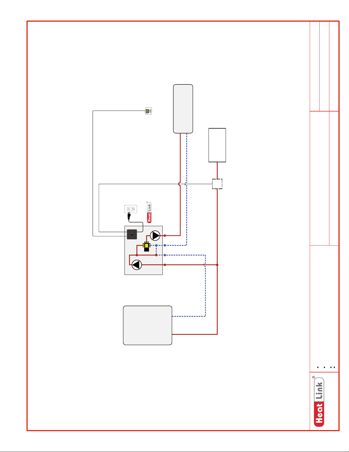
SCH-TWH-M001
SCH-MRIB-R001
SCH-TWH-E001
Schematic #:
Wiring detail see:
Rough-in wiring see:
Check
Thermostat
Heating Load
to House
DHW Supply
FS
Optional
DHW Priority Switch
Generic
TWH Series
Panel(s):
Heat Source:
Generic – Single Zone
Heat Load(s):
2013-03-18
Date:
Panel
TWH070P/
TWH070XP
Pump
Primary
Valve in
Heat
Source
Drawings are for HeatLink suggested system layout only! User must determine
if system layout will work for their particular application.
Air vents, expansion tanks, pressure relief valves, etc. for heat source as per
local codes.
Use isolation ball valves for all circuits and components.
Notes:
Local codes, regulations, and authorities have final jurisdiction.
1-866-661-5332
www.heatlinkgroup.com
83
Page 86
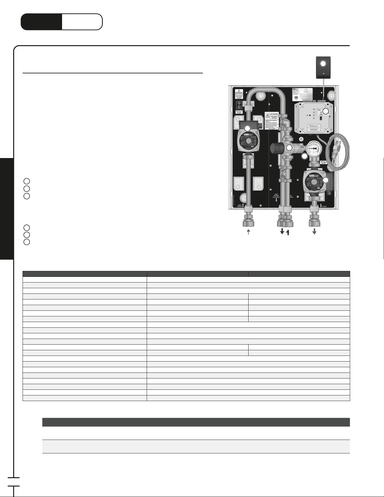
LinkHeat
TWH070Z
3
www.heatlink.com
®
TWH – Tankless Water Heater Panels with Zoning
Canada - July 1, 2014
TWH 70 MBH Tankless Water Heater Mixing Panels with Zoning
Stk# TWH070Z & TWH070XPZ
The TWH Tankless Water Heater Mixing Panel’s primary application is as a
multizone mixing device for tankless DHW heaters. Both the primary and
secondary pumps are activated once every 24 hours, for 15 minutes, to
ensure that potable water in the piping is not stagnant. The power box has
thermostat inputs and actuator outputs for up to four zones (two actuators
per zone). At this time, a DHW priority option for these panels is not
available.
When the panel receives a call for heat, both pumps are activated, and the
thermostatic control head in the 3-way mixing valve will automatically
regulate the water temperature in the secondary circuit. The TWH070XPZ is
designed for applications where there is an extremely high ow resistance in
the heat source.
Panel Components
1
Primary Pump with Check Valve
Secondary Pump
2
Power Box with 6' Power Cord
3
• 24hr Timer for Potable Applications
• Auxiliary Dry Contacts for Heat Source
• Thermostat Inputs and Actuator Outputs for 4 Zones
• Bypass Function
24Vac Plug-in Transformer
4
5
3-Way Thermostatic Mixing Valve
6
Thermometer
Panel Enclosure (not shown)
;
Mechanical Room in a Box
TWH070Z
Primary
Supply
1
Primary
Return
(lower pipe)
5
Secondary
Return
(upper pipe)
6
4
3
2
Secondary
Supply
Listing cETLus
Conforms to CAN/CSA-C22 No.14, UL508
Dimensions 18.25"H x 16.25"W x 8"D
Nominal panel output 70,000 btu/hr 70,000 btu/hr
Primary nominal ow 4.0 US gpm @ 35°F ΔT 4.0 US gpm @ 35°F ΔT
Primary nominal pressure drop outside of panel 14 ft 24 ft
Secondary nominal ow 7 US gpm @ 20°F ΔT 7 US gpm @ 20°F ΔT
Secondary nominal pressure drop outside of panel 4 ft 4 ft
Max ambient temperature 120°F
Max water temperature 200°F
Min required ow for correct temp control 1 US gpm
Power supply: pre-wired on system controller 110 V(ac); max. current 2A
Primary circulator Non-ferrous, Grundfos UPS15-58
Secondary circulator Non-ferrous, Grundfos UPS15-58
Auxiliary terminal 1 dry contact, max. load 1.5A
Temperature control method 1" 3-Way thermostatic
Temperature control range 100°F - 145°F
Valve Cv 3.0
Piping
Piping connections 1" FNPT
Backplate 16 gauge galvanized steel
Enclosure Powder coated steel
Stk# Description Pkg Qty Carton Qty Unit List Price / Unit
Special
Order*
Special
Order*
TWH070Z TWH 70MBH Tankless Water Heater Mixing Panel with Zoning 1 ea.
TWH070XPZ
TWH 70MBH High Head Tankless Water Heater Mixing Panel
with Zoning
TWH070Z TWH070XPZ
Non-ferrous, Grundfos UPS26-99BFC
Non-ferrous, Grundfos UPS15-58
⁄4" 304 SS tubing
1 ea.
84
* Lead time may vary. Call to con rm time line.
Page 87
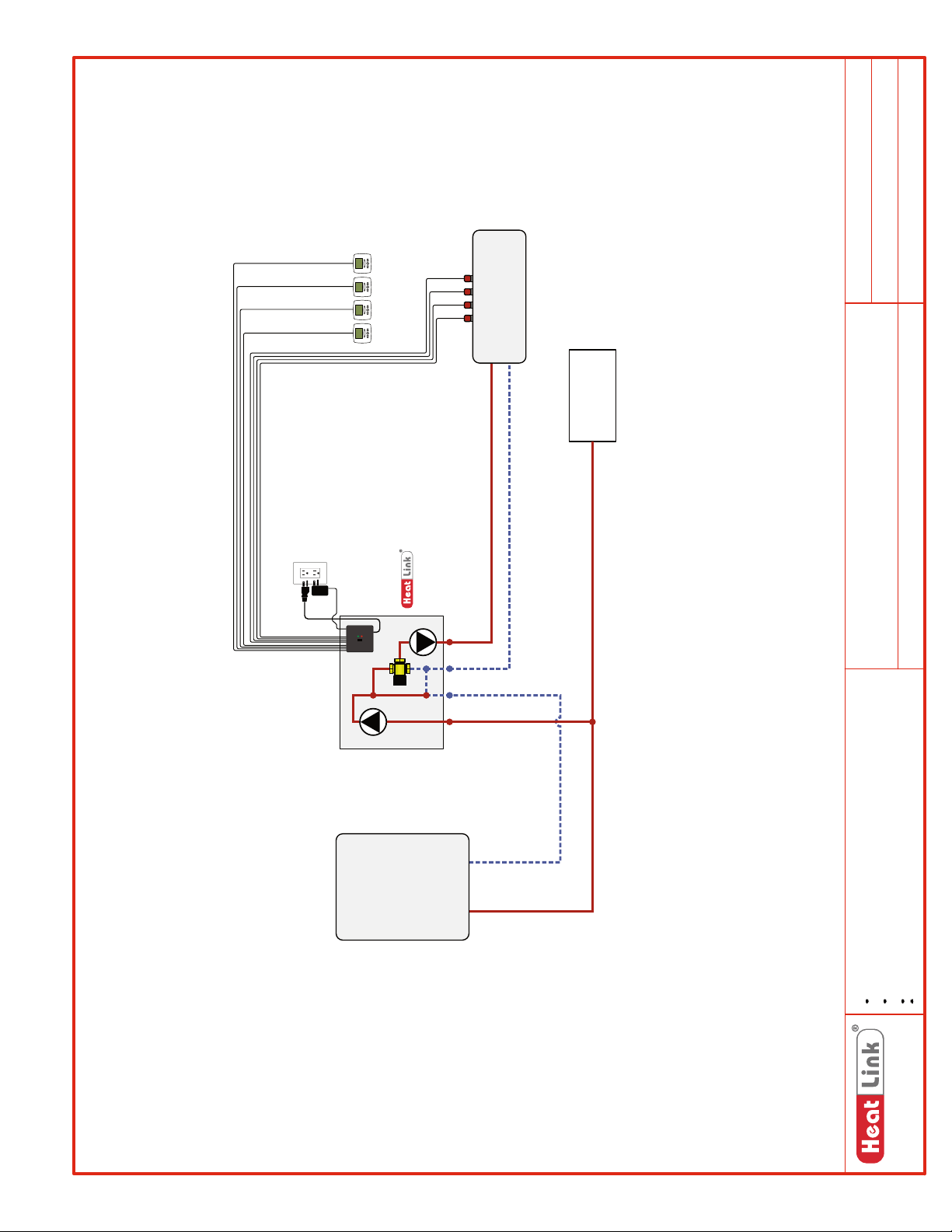
SCH-TWHZ-M001
SCH-MRIB-R006
SCH-TWHZ-E001
Schematic #:
Wiring detail see:
Rough-in wiring see:
Heating Load
Up to 4 Zones
to House
DHW Supply
Generic
TWHZ Series
Panel(s):
Heat Source:
Generic – Up to 4 Zones
Heat Load(s):
2013-05-22
Date:
Panel
TWH070Z/
TWH070XPZ
Check
Pump
Primary
Valve in
Heat
Source
Drawings are for HeatLink suggested system layout only! User must determine
if system layout will work for their particular application.
Air vents, expansion tanks, pressure relief valves, etc. for heat source as per
local codes.
Use isolation ball valves for all circuits and components.
Notes:
Local codes, regulations, and authorities have final jurisdiction.
1-866-661-5332
www.heatlinkgroup.com
85
Page 88
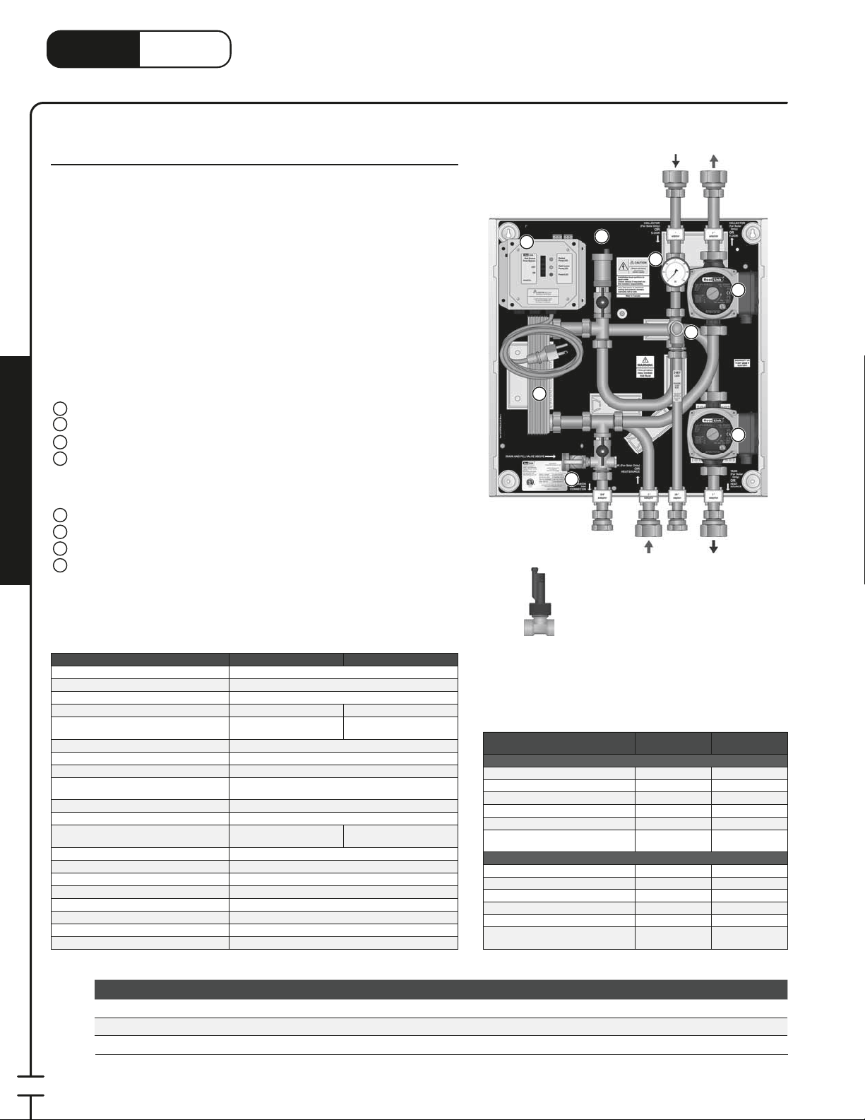
LinkHeat
1
3
1
www.heatlink.com
®
HEP – Isolation Heat Exchanger Panels
Canada - July 1, 2014
HEP Isolation Heat Exchanger Panels
HEP Series
The main application of the HEP Isolation Heat Exchanger Panel is to provide
single wall isolation between a DHW tank and a heating system. While
other applications are possible, it is important to note that this panel is not
a temperature control device. The secondary water temperature is wholly
dependent on the temperature of the primary supply water. When the panel
receives a call for heat, it activates both primary and secondary pumps.
The primary pump is also activated once every 24 hours, for 15 minutes, to
ensure that potable water in the piping or heat exchanger is not stagnant.
The panel is pre-wired to work with a DHW priority switch which is mounted
outside the panel.
Panel Components
Primary Pump
1
2
Secondary Pump
Brazed Plate Heat Exchanger
3
Power Box with 6' Power Cord
4
• 24hr Timer for Potable Applications
• Bypass Function
• Auxiliary Dry Contacts for Heat Source
5
Pressure Relief Valve
6
Pressure Gauge
7
Automatic Air Vent
Mechanical Room in a Box
8
Drain and Fill Valve
Panel Enclosure (not shown)
;
HEP025P
Secondary
Return
4
3
7
6
8
Primary
Supply
Secondary
Supply
5
Primary
Return
2
1
Listing cETLus
Conforms to CAN/CSA-C22 No.14, UL508
Dimensions 18Weight 30 lbs 32.5 lbs
Nominal panel output
see conditions to the right
Max ambient temperature 120°F
Max water temperature 200°F
Settable uid temp range dependant on heat source temperature
Power supply:
pre-wired on system controller
Primary pump Non-ferrous, Grundfos UPS15-58
Secondary pump Non-ferrous, Grundfos UPS15-58
Heat exchanger
Auxiliary terminal Yes
DHW priority Optional @ ~0.5 US gpm DHW ow
Temperature control method None
Piping
Piping connections 1" FNPT, 3⁄4" FNPT
DHW priority switch connection
Backplate 16 gauge galvanized steel
Enclosure Powder coated steel
HEP025P HEP080P
⁄4"H × 18-1⁄4"W × 7-3⁄4"D
25,000 Btu/hr 80,000 Btu/hr
110 V(ac); max. current 2A
Single-wall brazed plate;
3×8-12
⁄2" FNPT (FLWSTCH optional)
Single-wall brazed plate;
⁄4" 304 SS tubing
3×8-30
Stk# Description Pkg Qty Carton Qty Unit List Price / Unit
HEP025P HEP 25MBH Isolation Heat Exchanger Panel 1 ea.
HEP080P HEP 80MBH Isolation Heat Exchanger Panel 1 ea.
FLWSWTCH Flow Switch for Domestic Hot Water Priority 1 ea.
FLWSWTCH
Panel Output Conditions
HEP025
Fluid type Water Water
Entering uid temp (°F) 140°F 100°F
Exiting uid temp (°F) 120°F 120°F
Flow rate (US gpm) 3 US gpm 3 US gpm
Pressure drop (ft head) 3 ft 2 ft
Allowable pressure drop outside of
Panel (ft head)
HEP080
Fluid type Water Water
Entering uid temp (°F) 140°F 100°F
Exiting uid temp (°F) 120°F 120°F
Flow rate (US gpm) 8.1 US gpm 8.1 US gpm
Pressure drop (ft head) 3.9 ft 3.7 ft
Allowable pressure drop outside of
Panel (ft head)
Primary
Side Secondary Side
13 ft 14 ft
6 ft 6 ft
86
Page 89
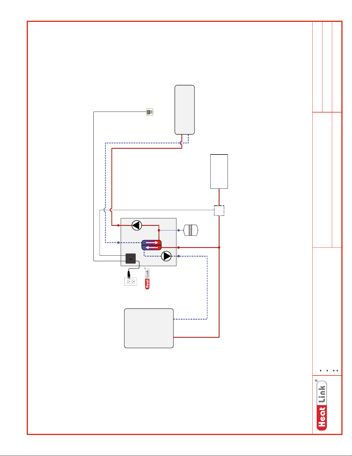
SCH-HEP-M001
SCH-MRIB-R001
SCH-HEP-E001
Schematic #:
Wiring detail see:
Rough-in wiring see:
Thermostat
Panel
HEP Series
Heating Load
to House
DHW Supply
FS
Optional
DHW Priority Switch
Generic
HEP Series
Generic – Single Zone
Panel(s):
Heat Source:
Heat Load(s):
2013-02-18
Date:
Heat
Source
Drawings are for HeatLink suggested system layout only! User must determine
if system layout will work for their particular application.
Air vents, expansion tanks, pressure relief valves, etc. for heat source as per
local codes.
Use isolation ball valves for all circuits and components.
Notes:
Local codes, regulations, and authorities have final jurisdiction.
1-866-661-5332
www.heatlinkgroup.com
87
Page 90
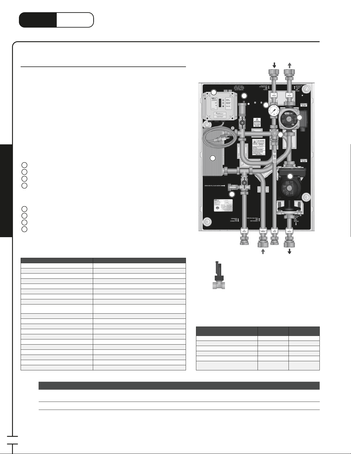
LinkHeat
3
3
3
1
www.heatlink.com
®
HEP – Isolation Heat Exchanger Panels
Canada - July 1, 2014
HEP Isolation Heat Exchanger Panels
HEP Series
The main application of the HEP Isolation Heat Exchanger Panel is to provide
single wall isolation between a DHW tank and a heating system. While
other applications are possible, it is important to note that this panel is not
a temperature control device. The secondary water temperature is wholly
dependent on the temperature of the primary supply water. The HEP095P is
designed for applications where there is an extremely high ow resistance
in the heat source. When the panel receives a call for heat, it activates both
primary and secondary pumps. The primary pump is also activated once
every 24 hours, for 15 minutes, to ensure that potable water in the piping or
heat exchanger is not stagnant.
The panel is pre-wired to work with a DHW priority switch which is mounted
outside the panel.
Panel Components
1
Primary Pump
2
Secondary Pump
3
Brazed Plate Heat Exchanger
4
Power Box with 6' Power Cord
• 24hr Timer for Potable Applications
• Bypass Function
• Auxiliary Dry Contacts for Heat Source
5
Pressure Relief Valve
6
Pressure Gauge
7
Automatic Air Vent
Mechanical Room in a Box
8
Drain and Fill Valve
Panel Enclosure (not shown)
;
Secondary
Return
4
3
7
6
8
Secondary
Supply
5
1
2
Listing cETLus
Conforms to CAN/CSA-C22 No.14, UL508
Dimensions 24"H × 18Weight 46.5 lbs
Nominal panel output 95,000 Btu/hr *see conditions to the right
Max ambient temperature 120°F
Max water temperature 200°F
Settable uid temp range dependant on heat source temperature
Power supply:
pre-wired on system controller
Primary pump Non-ferrous, Grundfos UPS26-99BFC
Secondary pump Non-ferrous, Grundfos UPS15-58
Heat exchanger Single-wall brazed plate; 3×8-30
Auxiliary terminal 1 dry contact, max. load 1.5A
DHW priority Optional @ ~0.5 US gpm DHW ow
Temperature control method None
Piping
Piping connections 1" FNPT,
DHW priority switch connection
Backplate 16 gauge galvanized steel
Enclosure Powder coated steel
HEP095P
⁄4"W × 7-3⁄4"D
110 V(ac); max. current 3A
⁄4" 304 SS tubing
⁄2" FNPT (FLWSWTCH optional)
⁄4" FNPT
Stk# Description Pkg Qty Carton Qty Unit List Price / Unit
Special
Order*
HEP095P HEP 95MBH Isolation Heat Exchanger Panel 1 ea.
FLWSWTCH Flow Switch for Domestic Hot Water Priority 1 ea.
Primary
Supply
FLWSWTCH
Panel Output Conditions
Fluid type Water Water
Entering uid temp (°F) 140°F 100°F
Exiting uid temp (°F) 125°F 127°F
Flow rate (US gpm) 13 US gpm 7 US gpm
Pressure drop (ft head) 10 ft 3 ft
Allowable pressure drop outside of
Panel (ft head)
Primary
Primary
Return
Side Secondary Side
10 ft 9 ft
88
* Lead time may vary. Call to con rm time line.
Page 91
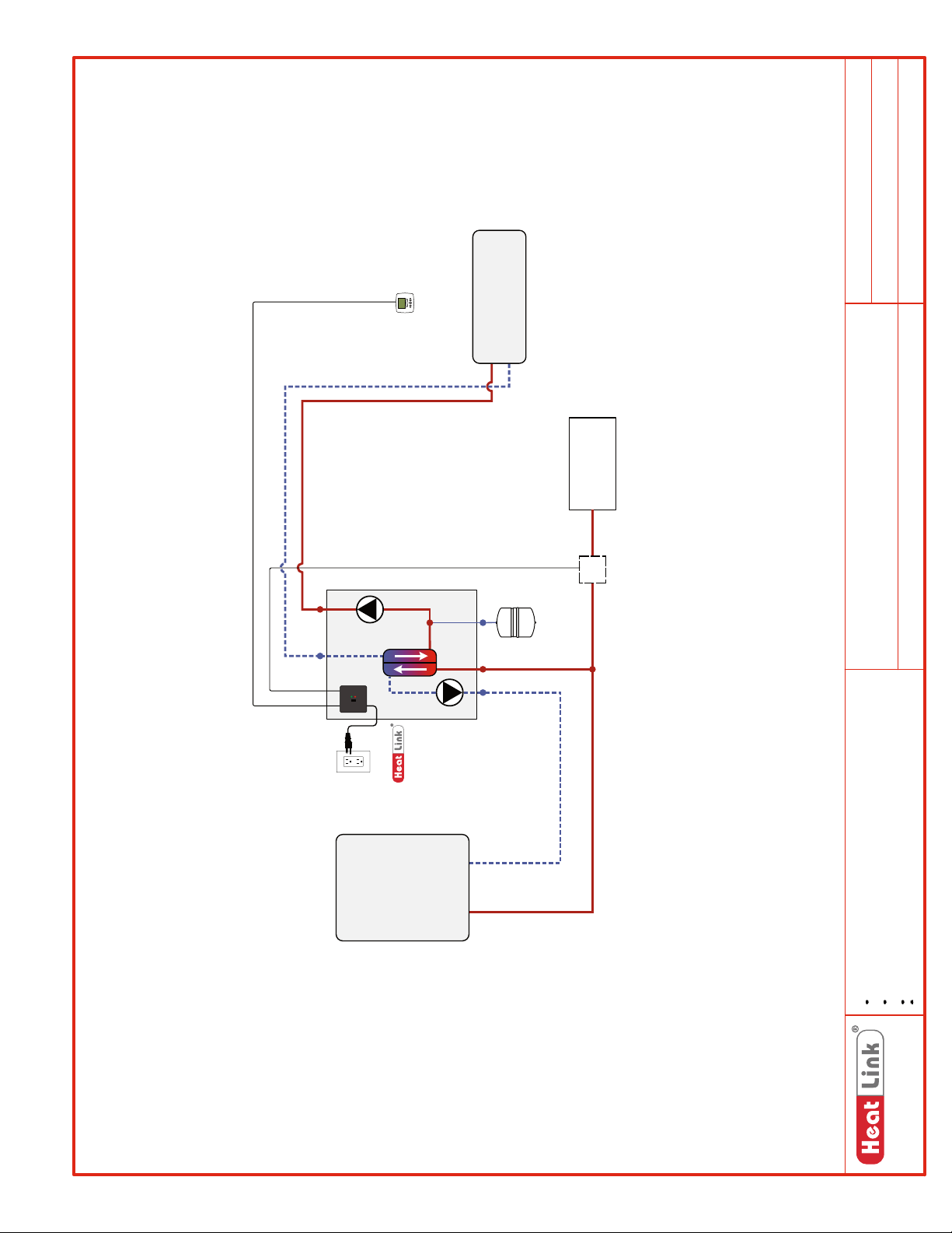
SCH-HEP-M001
SCH-MRIB-R001
SCH-HEP-E001
Schematic #:
Wiring detail see:
Rough-in wiring see:
Thermostat
Panel
HEP Series
Heating Load
to House
DHW Supply
FS
Optional
DHW Priority Switch
Generic
HEP Series
Generic – Single Zone
Panel(s):
Heat Source:
Heat Load(s):
2013-02-18
Date:
Heat
Source
Drawings are for HeatLink suggested system layout only! User must determine
if system layout will work for their particular application.
Air vents, expansion tanks, pressure relief valves, etc. for heat source as per
local codes.
Use isolation ball valves for all circuits and components.
Notes:
Local codes, regulations, and authorities have final jurisdiction.
1-866-661-5332
www.heatlinkgroup.com
89
Page 92
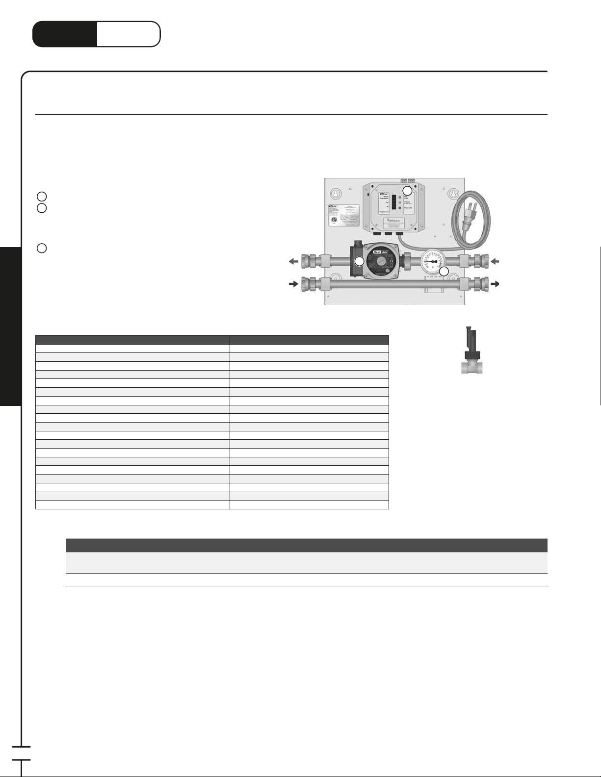
®
1
3
3
1
LinkHeat
www.heatlink.com
WHP – Water Heater Panel
Canada - July 1, 2014
WHP 130 MBH Water Heater Pump Panel with optional DHW Priority
Stk# WHP130P
The WHP Water Heater Pump Panel’s primary application is as a ow activated DHW priority switched pump. Intended to be used with DHW
tanks as a heat source, the pump is activated once every 24 hours, for 15 minutes, to ensure that potable water in the piping is not stagnant.
The WHP130P is compatible with the optional ow switch (FLWSWTCH) that turns o the primary pump when there is ow in the regular
DHW line.
Panel Components
1
Primary Pump
2
Power Box with 6' Power Cord
• 24hr Timer for Potable Applications
• Bypass Function
• Auxiliary Dry Contacts for Heat Source
Thermometer
3
Panel Enclosure (not shown)
;
Listing cETLus
Conforms to CAN/CSA-C22 No.14, UL508
Dimensions 12"H × 13Weight 21 lbs.
Nominal panel output 130,000 Btu/h
Mechanical Room in a Box
Nominal ow 10 US gpm @ 26°F ΔT
Nominal pressure drop outside of panel 8 ft
Max ambient temperature 120°F
Max water temperature 200°F
Power supply: pre-wired on system controller 110 V(ac): max. current 1A
Pump Non-ferrous, Grundfos UPS15-58
Auxiliary terminal 1 dry contact, max. load 1.5A
DHW priority Optional @ ~0.5 US gpm DHW ow
Temperature control method None
Piping
Piping connections
DHW priority switch connection
Backplate 16 gauge galvanized steel
Enclosure Powder coated steel
High Temp
Supply
High Temp
Return
WHP130P
⁄4" 304 SS tubing
⁄4" FNPT
⁄2" FNPT (FLWSTCH optional)
⁄4"W × 7"D
2
1
3
FLWSWTCH
Primary
Supply
Primary
Return
90
Special
Order*
Stk# Description Pkg Qty Carton Qty Unit List Price / Unit
WHP130P
WHP 130MBH Water Heater Pump Panel (DHW Priority
Optional)
1 ea.
FLWSWTCH Flow Switch for Domestic Hot Water Priority 1 ea.
* Lead time may vary. Call to con rm time line.
Page 93
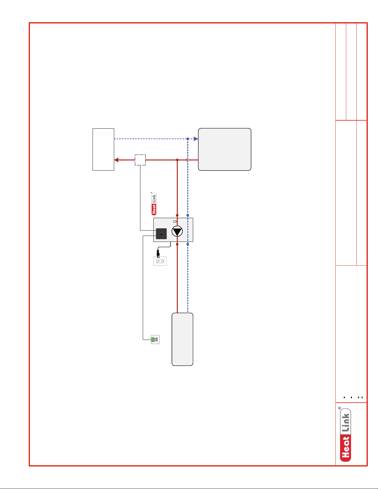
SCH-WHP-M001
SCH-MRIB-R001
SCH-WHP-E001
Schematic #:
Wiring detail see:
Rough-in wiring see:
House
DHW to and from
FS
Heat
Source
Optional
DHW Priority Switch
Panel
WHP130P
T
Generic
WHP130P
Generic – Single Zone
2013-05-23
Panel(s):
Heat Source:
Heat Load(s):
Date:
Thermostat
Heating Load
Drawings are for HeatLink suggested system layout only! User must determine
if system layout will work for their particular application.
Air vents, expansion tanks, pressure relief valves, etc. for heat source as per
local codes.
Use isolation ball valves for all circuits and components.
Notes:
Local codes, regulations, and authorities have final jurisdiction.
1-866-661-5332
www.heatlinkgroup.com
91
Page 94
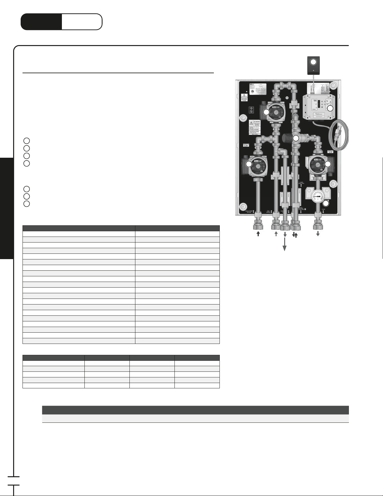
LinkHeat
1
3
www.heatlink.com
®
CDP – 200 MBH 2-Temperature Combi DHW Panel
Canada - July 1, 2014
CDP 200 MBH 2-Temperature System Panel
Stk# CDP200R2
The CDP200R2 Combi Panel operates as a high/low temperature distribution
center, with a boiler (or other non-DHW appliance) as a heat source. The
CDP200R2 has one high temperature branch that can be used for an indirect- red
DHW tank (with priority), or a high temperature heating application such as fan
coils or baseboards. The thermostatic control head in the 3-way mixing valve will
automatically regulate the water temperature in the secondary circuit.
Panel Components
1
Primary Pump
2
Mixed Temp Pump
3
DHW / High Temp Pump
4
Power Box with 6' Power Cord
• Purge Timer on All Circuits
• Bypass Function
• Auxiliary Dry Contacts for Heat Source
3-Way Thermostatic Mixing Valve
5
24Vac Plug-in Transformer
6
Thermometer
7
Panel Enclosure (not shown)
;
Listing cETLus
Conforms to CAN/CSA-C22 No.14, UL508
Dimensions 18-
Mechanical Room in a Box
Weight 41.5 lbs.
Nominal panel output* - see conditions below 200,000 Btu/hr*
Max ambient temperature 120°F
Max water temperature 200°F
Settable uid temp range 100-145°F
Min required ow for correct temp control 1 US gpm
Power supply: pre-wired on system controller 110 V(ac); max. current 3A
Primary pump Non-ferrous, Grundfos UPS15-58
Low temp pump Non-ferrous, Grundfos UPS15-58
High temp/DHW pump Non-ferrous, Grundfos UPS15-58
Auxiliary terminal 2 dry contacts, max. load 1.5A
Temperature control method 1" 3-Way thermostatic
Mix Valve Cv 3.0
Piping
Piping connections 1" FNPT
Backplate 16 gauge galvanized steel
Enclosure Powder coated steel
CDP200R2
⁄4"H × 16-1⁄4"W × 7-3⁄4"D
⁄4" 304 SS tubing
3
DHW /
High Temp
Return
1
Primary
Supply
DHW / High
Temp Supply
5
Secondary
Return
(upper pipe)
Primary
Return
(lower pipe)
6
Secondary
Supply
4
2
7
Panel Output Conditions Primary Mixed Temp DHW / High Temp
Nominal output (Btu/h) 200,000 60,000 140,000
Fluid type Water Water Water
ΔT (°F) 40°F 20°F 26°F
Flow rate (US gpm) 10 US gpm 6 US gpm 10 US gpm
Pressure drop (ft head) 8 ft 4 ft 8 ft
Stk# Description Pkg Qty Carton Qty Unit List Price / Unit
CDP200R2 CDP 200MBH 2-Temp System Panel with 3 Pumps Rev2 1 ea.
92
Page 95
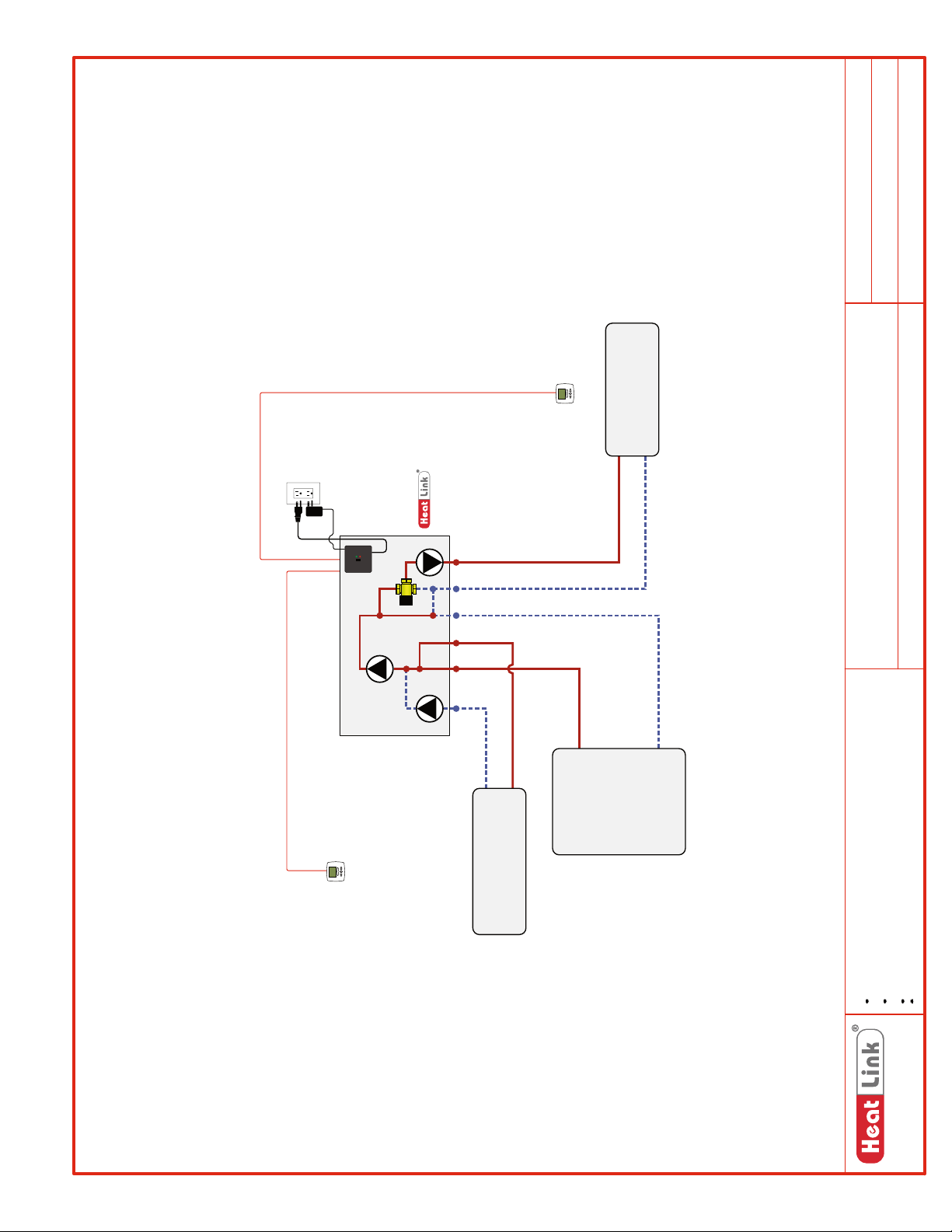
SCH-CDP-M001
SCH-MRIB-R001
SCH-CDP-E001
Schematic #:
Wiring detail see:
Rough-in wiring see:
Check
Thermostat
Panel
Valve in
Primary,
Radiant,
And DHW/
CDP200R2
Hi Temp
Pumps
Heating Load
Heat
Source
(Low Temp)
Generic
CDP200R2
Generic – Low Temp, Generic – High Temp
2013-05-15
Panel(s):
Heat Source:
Heat Load(s):
Date:
Thermostat
Heating Load
(DHW / High Temp)
Drawings are for HeatLink suggested system layout only! User must determine
if system layout will work for their particular application.
Air vents, expansion tanks, pressure relief valves, etc. for heat source as per
local codes.
Use isolation ball valves for all circuits and components.
Notes:
Local codes, regulations, and authorities have final jurisdiction.
1-866-661-5332
www.heatlinkgroup.com
93
Page 96
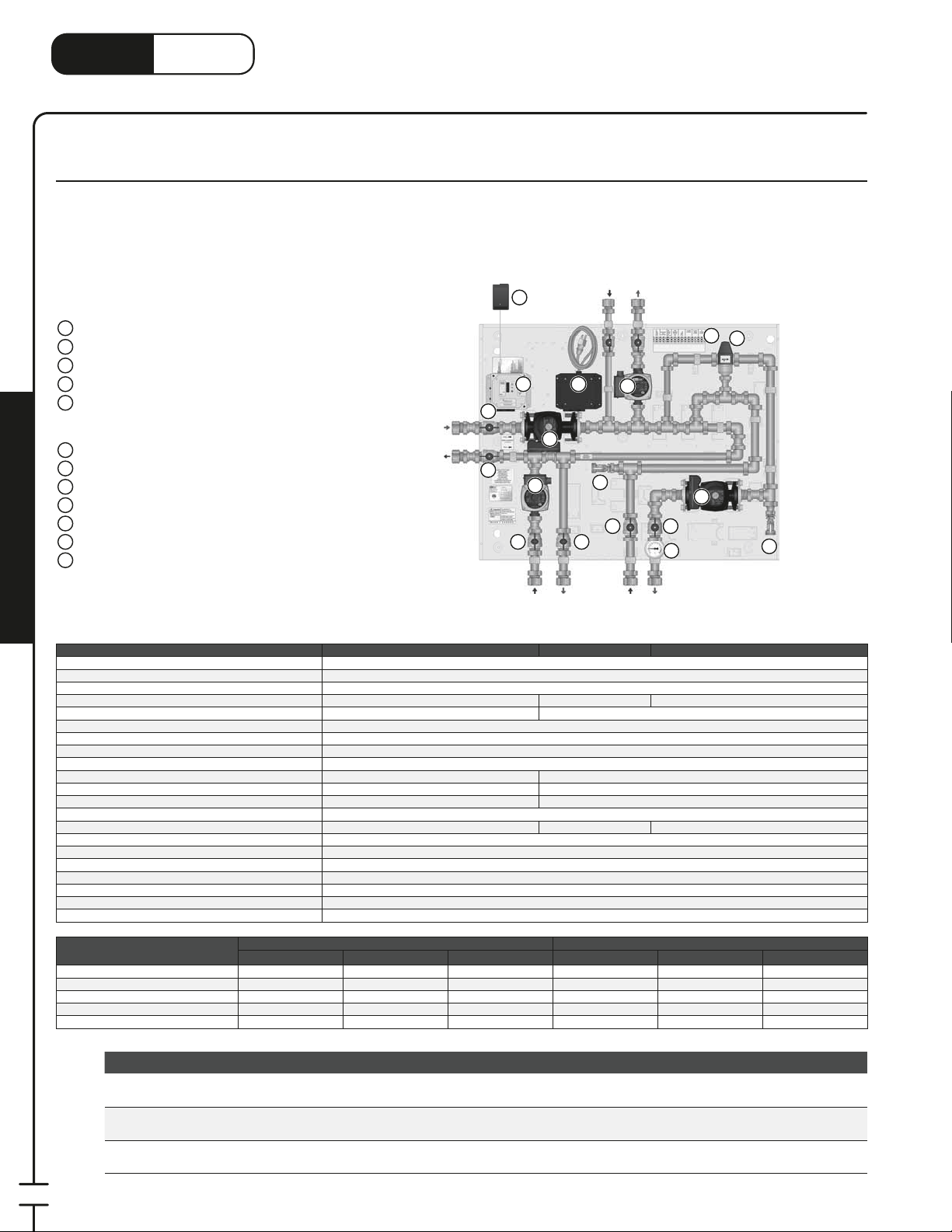
®
1
LinkHeat
www.heatlink.com
CDP – 220-250 MBH 2 or 3 Temperature Combi DHW Panels
Canada - July 1, 2014
CDP 220-250 MBH 2-Temperature Combi DHW System Panels
Stk# CDP220R2 & CDP250R2
The CDP220R2 and 250R2 Combi Panels operate as high/low temperature distribution centers, with a boiler (or other non-DHW appliance)
as a heat source. The CDP panels each have two high temperature branches with pumps, one for the indirect- red DHW tank (with priority)
and one for the high temperature heating application. The thermostatic control head in the 3-way mixing valve will automatically regulate
the water temperature in the secondary circuit. The panels have three outputs to the boiler.
Return
4
12
11 11
Mixed
Temp
Return
High Temp
Supply
10
Mixed
Temp
Supply
2
7
CDP250R2
9
12
Note: these panels are not compatible with IBC boilers.
Panel Components
1
Primary Pump
2
Mixed Temp Pump
3
DHW Pump with Priority
High Temp Pump (CDP220R2 and CDP250R2 only)
Power Box
5
• Purge Timers on All Circuits
• Bypass Function
6
Relay Box with 6' Power Cord
7
Terminal Strip
8
24Vac Plug-in Transformer
9
3-Way Thermostatic Mixing Valve
10
Thermometer
11 11 11
Isolation Valve
Drain and Fill Valve
12
Panel Enclosure (not shown)
;
Primary
Supply
Primary
Return
Mechanical Room in a Box
Listing cETLus
Conforms to CAN/CSA-C22 No.14, UL508
Dimensions 30Weight 108 lbs 118 lbs 121 lbs
Nominal panel output - see conditions below 220,000 Btu/h* 250,000 Btu/h*
Max ambient temperature 120°F
Max water temperature 200°F
Settable uid temp range 110-140°F
Min required ow for correct temp control 1 US gpm
Power supply: pre-wired on system controller 110 V(ac); max. current 5A 110 V(ac); max. current 6A
Primary circulator Non-ferrous, Grundfos UPS15-58 Ferrous, Grundfos UPS26-99FC
Low temp circulator Non-ferrous, Grundfos UPS15-58 Ferrous, Grundfos UPS26-99FC
DHW circulator Non-ferrous, Grundfos UPS15-58
High temp circulator Non-ferrous, Grundfos UPS15-58 n/a Non-ferrous, Grundfos UPS15-58
Auxiliary terminal 3 dry contacts, max. load 1.5A
Temperature control method 1" 3-way thermostatic mixing valve
Mix Valve Cv 3.7
Piping 1" 304 Stainless steel tubing
Piping connections 1" FNPT
Backplate Galvanized steel
Enclosure Powder coated steel
CDP220R2 CDP250P3R2 CDP250R2
8
54
11
11
DHW
Return
High Temp
6
1
3
DHW
Supply
⁄4"H × 38-3⁄8"W × 7-7⁄8"D
Panel Output Conditions
Nominal output (Btu/h) 220,000 70,000 150,000 255,000 100,000 150,000
Fluid type Water Water Water Water Water Water
ΔT (°F) 40°F 20°F 30°F 30°F 20°F 30°F
Flow rate (US gpm) 11 US gpm 7 US gpm 10 US gpm 17 US gpm 10 US gpm 10 US gpm
Pressure drop (ft head) 7 ft 4 ft 8 ft 17 ft 7 ft 8 ft
Primary Mixed Temp High Temp Primary Mixed Temp High Temp
CDP220R2 CDP250P3R2 & CDP250R2
Stk# Description Pkg Qty Carton Qty Unit List Price / Unit
CDP 220MBH 2-Temp Combi DHW System Panel with 4
Pumps Rev2
CDP 250MBH 2-Temp Combi DHW System Panel with 3
Pumps Rev2
CDP 250MBH 2-Temp Combi DHW System Panel with 4
Pumps Rev2
1 ea.
1 ea.
1 ea.
* Lead time may vary. Call to con rm time line.
94
Special
Order*
Special
Order*
Special
Order*
CDP220R2
CDP250P3R2
CDP250R2
Page 97
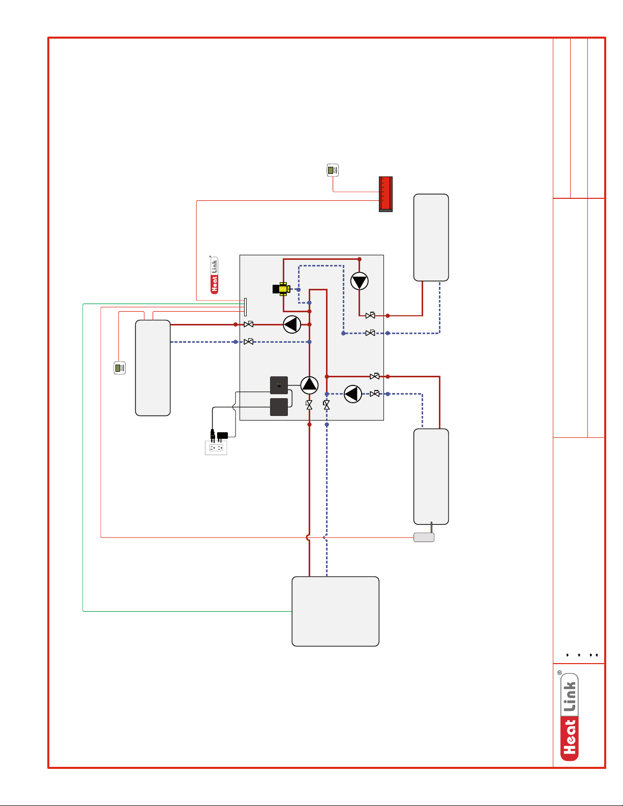
(High Temp)
Heating Load
SCH-CDP-M007
Schematic #:
Wiring detail see:
Rough-in wiring see:
Heating Load
(Mixed Temp)
Panel
CDP250R2
CDP220R2/
Generic
CDP220R2/CDP250R2
Generic
2013-06-18
Panel(s):
Heat Source:
Heat Load(s):
Date:
Heat
Source
Heating Load
(DHW)
Drawings are for HeatLink suggested system layout only! User must determine
if system layout will work for their particular application.
Air vents, expansion tanks, pressure relief valves, etc. for heat source as per
local codes.
Use isolation ball valves for all circuits and components.
Notes:
Local codes, regulations, and authorities have final jurisdiction.
1-866-661-5332
www.heatlinkgroup.com
95
Page 98
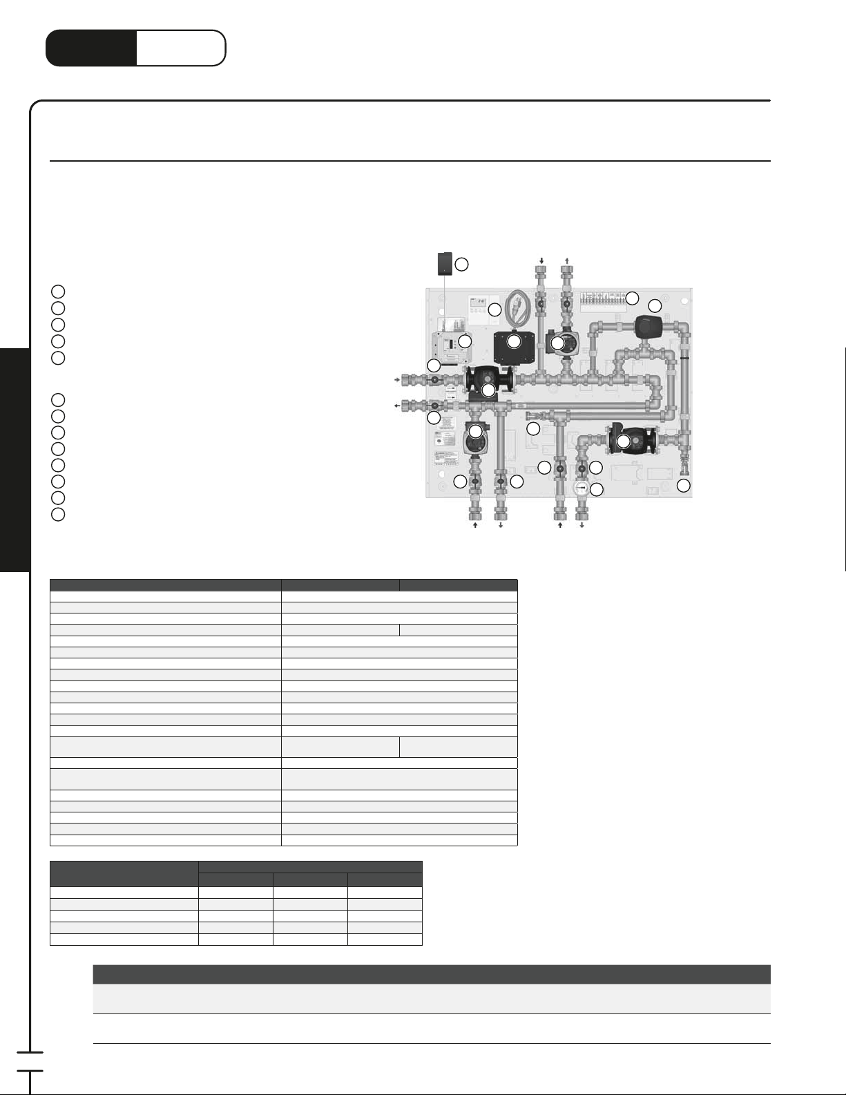
®
LinkHeat
www.heatlink.com
CDP – 310 MBH 2 or 3 Temperature Combi DHW Panels
Canada - July 1, 2014
CDP 310 MBH 2-Temperature System Panels with Outdoor Reset
Stk# CDP310RP3 & CDP310RP4
The CDP310R Combi Panels operate as high/low temperature distribution centers, with a boiler (or other non-DHW appliance) as a heat
source. The CDP310R panels each have two high temperature branches, one for the indirect- red DHW tank (with priority) and one for the
high temperature heating application. The #31355 Compact Mixing Control with the 3-way mixing valve and actuator will automatically
regulate the water temperature in the secondary circuit. The panels have three outputs to the boiler.
Note: these panels are not compatible with IBC boilers.
Panel Components
1
Primary Pump
2
Mixed Temp Pump
3
DHW Pump with Priority
High Temp Pump (CDP310RP4R2 only)
4
Power Box
5
• Purge Timers on All Circuits
• Bypass Function
6
Relay Box with 6' Power Cord
7
Terminal Strip
8
24Vac Plug-in Transformer
9
Compact Reset Control (#31355)
10
3-Way Mixing Valve with Motor
11
Thermometer
Isolation Valve
12
Drain and Fill Valve
13
Panel Enclosure (not shown)
;
Mechanical Room in a Box
Primary
Supply
Primary
Return
12
12
12 12
Return
8
5
DHW
3
9
1
DHW
Supply
High Temp
6
Return
4
13
12 12
Mixed
Temp
Return
High Temp
Supply
11
Mixed
Temp
Supply
CDP310RP4R2
7
10
2
13
Listing cETLus
Conforms to CAN/CSA-C22 No.14, UL508
Dimensions 34"H × 37"W × 6.75"D
Weight 119 lbs 122 lbs
Nominal panel output - see conditions below 310,000 Btu/h*
Max ambient temperature 120°F
Max water temperature 200°F
Settable uid temp range 110-140°F
Min required ow for correct temp control 1 US gpm
Power supply: pre-wired on system controller 110 V(ac); max. current 6A
Primary pump Ferrous, Grundfos UPS26-99FC
Low temp pump Ferrous, Grundfos UPS26-99FC
DHW pump Non-ferrous, Grundfos UPS15-58
High temp pump optional Non-ferrous, Grundfos
Auxiliary terminal Yes
Temperature control method 1" G 3-Way mixing valve with motor, controlled by
Mix Valve Cv 7.3
Piping 1" 304 SS tubing
Piping connections 1" FNPT
Backplate 16 gauge galvanized steel
Enclosure Powder coated steel
Panel Output Conditions
Nominal output (Btu/h) 255,000 160,000 150,000
Fluid type Water Water Water
ΔT (°F) 30°F 20°F 30°F
Flow rate (US gpm) 17 US gpm 16 US gpm 10 US gpm
Pressure drop (ft head) 17 ft 10 ft 8 ft
CDP310RP3 & CDP310RP4
Primary Mixed Temp High Temp
CDP310RP3R2 CDP310RP4R2
UPS15-58
compact reset control.
Stk# Description Pkg Qty Carton Qty Unit List Price / Unit
Special
Order*
Special
Order*
CDP310RP3R2
CDP310RP4R2
CDP 310MBH 2-Temp Combi DHW with 3 Pumps & Outdoor
Reset Rev2
CDP 310MBH 2-Temp Combi DHW with 4 Pumps & Outdoor
Reset Rev2
1 ea.
1 ea.
96
* Check with your local representative for availability.
Page 99
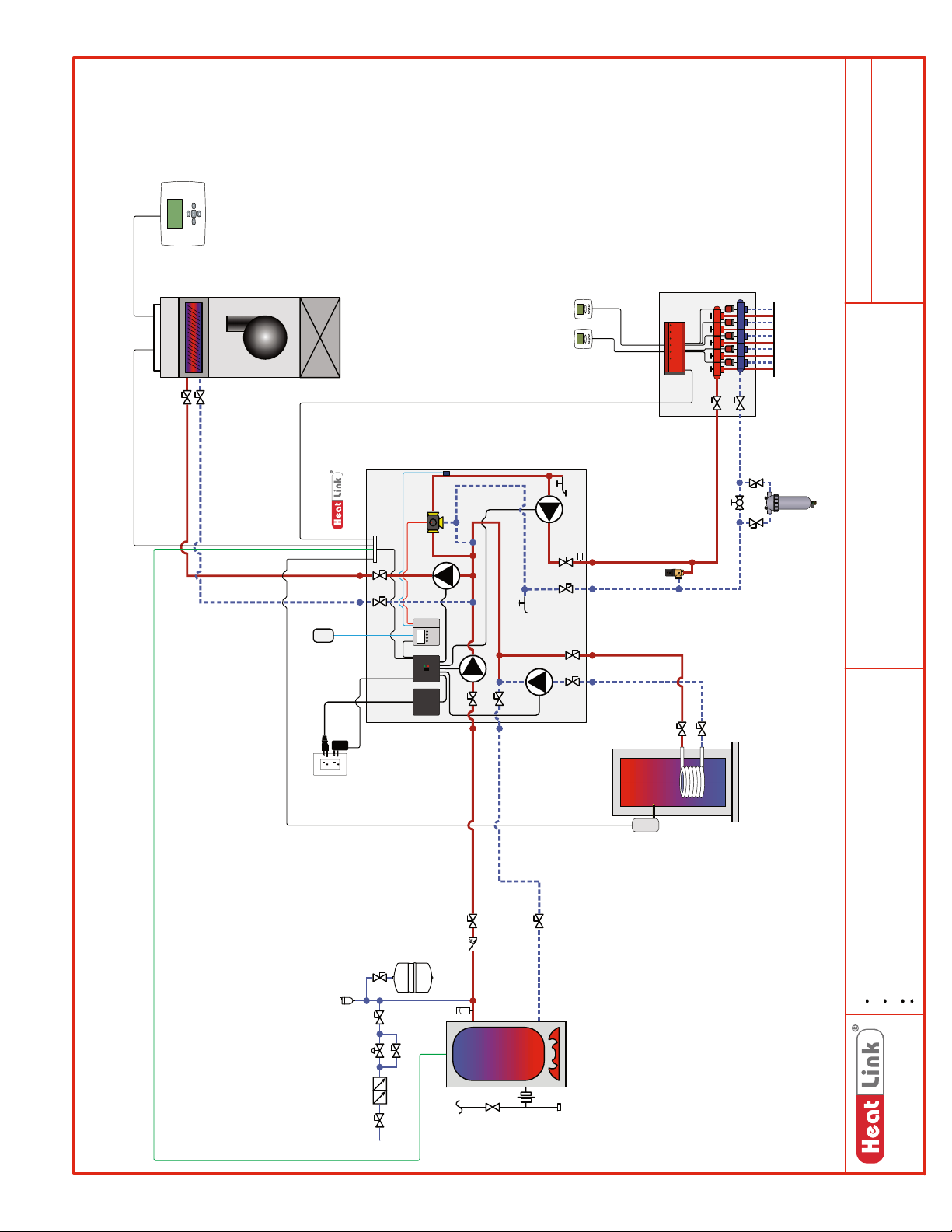
Heat/Cool
Thermostat
Rough-in wiring see:
SCH-MRIB-R004
Sensor
Outdoor
SCH-CDP-M009
SCH-CDP-E009
Schematic #:
Wiring detail see:
Rough-in wiring see:
Rough-in wiring see:
SCH-MRIB-R002
Thermostats
Manifold
Radiant Heating
Panel
CDP310RP4R2
Recommended
Pressure
T
Bypass Valve
Recommended
Sidestream Filter
Boiler
CDP310RP4R2
Panel(s):
Heat Source:
IFHWH, Fan Coil, Radiant Heating
Heat Load(s):
2013-06-18
Date:
Rough-in wiring see:
SCH-MRIB-R007
Heater
Aquastat
Hot Water
Indirect Fired
Drawings are for HeatLink suggested system layout only! User must determine
if system layout will work for their particular application.
Air vents, expansion tanks, pressure relief valves, etc. for heat source as per
local codes.
Use isolation ball valves for all circuits and components.
Notes:
Local codes, regulations, and authorities have final jurisdiction.
Boiler
1-866-661-5332
www.heatlinkgroup.com
97
Page 100
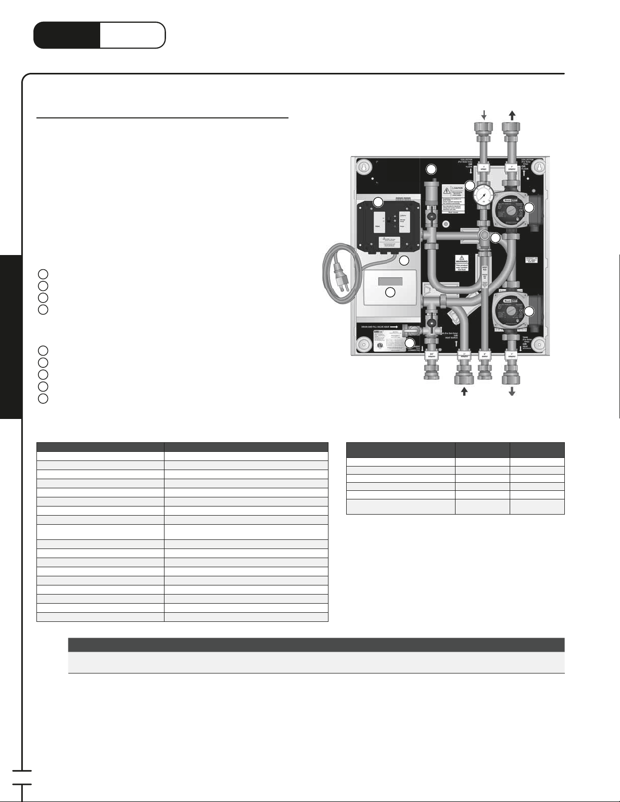
LinkHeat
1
3
www.heatlink.com
®
Solar Heat Exchanger Panel
Canada - July 1, 2014
SOL 80 MBH Solar Heat Exchanger Panel
Stk# SOL080
The SOL080 Heat Exchanger Panel creates an interface between
the solar collectors and the system tanks. The Panel integrates
all of the control components of a solar system into an attractive
compact appliance. Features include a heat exchanger to isolate
the glycol in the solar collector circuit from the domestic water,
and separate pumps for each circuit. The secondary pump is
activated once every 24 hours, for 15 minutes, to ensure that
potable water in the piping or heat exchanger is not stagnant.
Panel Components
1
Brazed Plate Heat Exchanger (hidden)
2
Collector Pump
3
Secondary Pump
4
Power Box with 6' Power Cord
• Timer for Secondary (Tank) Loop
• Bypass Function
• Auxiliary Dry Contacts for Heat Source
5
Pressure Relief Valve
6
Pressure Gauge
7
Automatic Air Vent
8
Drain and Fill Valve
9
Solar Control
Mechanical Room in a Box
Panel Enclosure (not shown)
;
Collector
Return
7
6
4
1
9
8
Expansion
Tank
Secondary
Return
Pressure
Relief
Collector
Supply
5
Secondary
Supply
2
3
Listing cETLus
Conforms to CAN⁄CSA-C22 No.14, UL508
Dimensions 18"H × 21"W × 10Weight 32.5 lbs.
Nominal panel output 80,000 Btu/hr *see conditions to the right
Max ambient temperature 120°F
Max water temperature 200°F
Settable uid temp range n/a
Power supply
pre wired on system controller
Primary pump Non-ferrous, Grundfos UPS15-58
Secondary pump Non-ferrous, Grundfos UPS15-58
Heat exchanger Single-wall Brazed Plate; 3×8-20
Auxiliary terminal 1 dry contact, max 1.5A
Temperature control method None
Piping
Piping connections 1" FNPT
Backplate 16 gauge galvanized steel
Enclosure Powder coated steel
SOL080
⁄2"D
110 V(ac); max. current 2A
⁄4" 304 SS tubing
Stk# Description Pkg Qty Carton Qty Unit List Price / Unit
Special
Order*
SOL080 SOL 80MBH Solar Heat Exchanger Panel 1 ea.
Panel Output Conditions
Fluid type 50% Glycol Water
Entering uid temp (°F) 160°F 115°F
Exiting uid temp (°F) 120°F 150°F
Flow rate (US gpm) 5 US gpm 4.5 US gpm
Pressure drop (ft head) 4.6 ft 3.0 ft
Allowable pressure drop outside of
Panel (ft head)
Collector
Side Secondary Side
8 ft 10 ft
98
* Lead time may vary. Call to con rm time line.
 Loading...