

Page 1
Page 48
SOLUXE 30 & 35
PRE-MIX
CONDENSING
COMBINATION BOILER
User Instructions
Page 2
Page 49
Natural Gas
Heat Line™ Boiler
British Gas Service Listing:
Soluxe 30 G.C..N. 47-157-10
Soluxe 35 G.C..N. 47-157-11
Notified Body
The manufacturer, in the drive for continuous improvement of his products, reserves the
right to modify the data expressed in the present documentation at any time and without
prior notice.
The present documentation is an informative support and it cannot be considered as a
contract towards third parties.
IMQ 51BR3326 Directive 90/396/EEC
51BR3335DR Directive 92/42/EEC
The Heat Line™ range of central heating boilers are manufactured from high quality
materials and designed for reliability and optimum performance.
Heat Line™ are committed to the continual development of their appliances and
reserve the right to make changes without notification to ensure their customers
benefit from the latest advances in combustion technology and energy conservation.
'Benchmark' Log Book
As part of the industry-wide initiative the boiler comes complete with an Installation,
Commissioning and Service Record Log Book. Please read the Log book carefully,
pages 46 & 47, and complete all sections, as required by law, relevant to the
appliance and installation. The details within the Log Book will be required in the
event of any warranty work.
On completion the Log Book must be left with the end user and the relevant sections
completed on each subsequent Service visit.
Page 3
Page 50
IMPORTANT INFORMATION
The Heat Line™ boiler is a high efficiency gas fired boiler and represents the highest
level of technology found in today’s gas boiler market.
In order to maintain peak efficiency along with optimum performance and reliability it
is essential that the boiler be serviced at least once per year by a competent person such
as a CORGI Registered Engineer.
All C.O.R.G.I. Registered Installers carry a C.O.R.G.I. ID card and have a registration
number, which should be recorded and entered on your benchmark log book. You can
check your Installer registration by contacting C.O.R.G.I. on 01256 372300
The boiler's 'Log Book' must be completed at each Service visit.
GAS SAFETY (INSTALLATION AND USE) REGULATIONS
It is a legal requirement that all gas appliances must be installed and serviced by a
competent or C.O.R.G.I. registered person in accordance with the above regulations.
Failure to install or service gas appliances correctly may invalidate your guarantee and
could lead to prosecution. It is in your interest and that of safety to ensure compliance
with the law.
For electrical safety the boiler must be earthed and protected by a 5 -amp fuse.
Note. In the event of a fault the appliance should not be used until a competent person
has corrected the fault.
VENTILATION
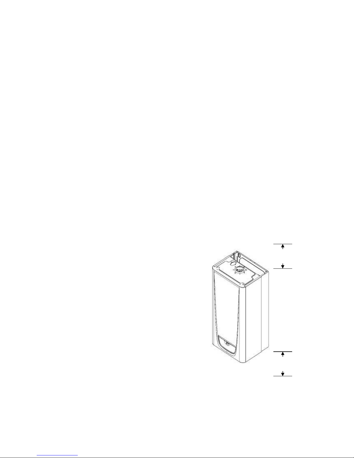
For maintenance and safety purposes, the
boiler has been installed with a minimum
space of 200mm above, 300mm below,
600mm to the front and 50mm to either
side of the boiler case.(figure 1) It is
essential that this space is not restricted by
the addition of shelves etc. fitted above or
below the boiler, or to the boiler sides. See
section 6 for detail
GENERAL DESCRIPTION OF THE
BOILER
The boiler is a combined domestic hot
water and central heating appliance. Its
internal control unit electronically
provides direct burner ignition and
combustion supervision along with
continuous modulation of the burner’s gas supply.
By means of a manual switch the boiler can be set to operate in one of two operating
modes, domestic hot water only or domestic hot water and central heating.
Figure 1
Page 4
Page 51
DOMESTIC HOT WATER MODE:
When hot water demand is requested the boiler will fire automatically. An integral
pump is then energised and hot water from the boilers primary circuit is circulated
through the secondary heat exchanger, allowing the instantaneous transferral of heat to
the incoming cold water. The secondary heat exchanger is protected against an internal
build up of lime scale by limiting the hot water temperature at the tap to a maximum of
65°C. Hot water will continue to flow through the tap until no longer required. When
the demand for hot water ceases the integral pump may continue to run for a short while
to dissipate any excess heat within the boiler.
DOMESTIC HOT WATER AND CENTRAL HEATING MODE:
When heating demand is requested the boiler will fire automatically. An integral pump
is then energised and hot water from the boilers primary circuit is circulated around the
heating systems pipe-work and radiators. The heat output from the boiler is
automatically adjusted by the boiler’s internal control unit to match the heating
demand. As the water temperature of the heating system increases the gas input to the
burner decreases, conserving energy and increasing efficiency. When the demand for
heating no longer exists, either the room thermostat is satisfied or the heating period has
ended, the burner will shut down and the boiler will revert to stand-by, waiting to
respond to the next heating demand. The integral pump may continue to run after shut
down for a short while to dissipate any excess heat within the boiler.
.
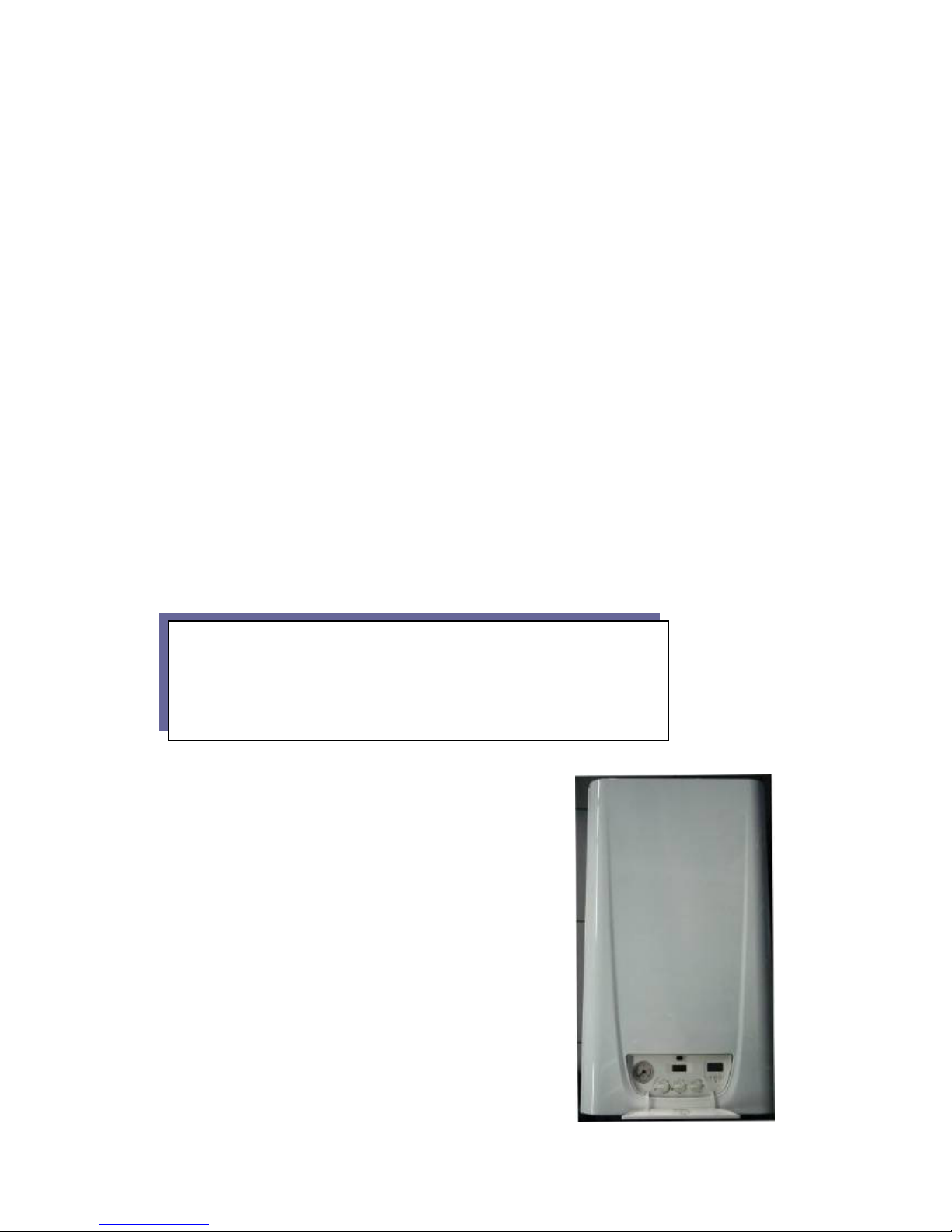
ACCESS TO THE BOILER CONTROLS.
The boiler controls are found behind the control panel
door, sited at the bottom of the boiler’s front case.
To open: press the doors retaining push catch
just above the display screen. (figure 2)
Figure 2
Please Note
. When domestic hot water is called for during the
heating mode, the boiler will automatically revert to domestic hot
water mode until the demand for hot water ceases.
NOTE: Depending on the boiler set up there may be a delay of
45secs before the boiler re-fires.
Page 5
Page 52
BOILER CONTROLS
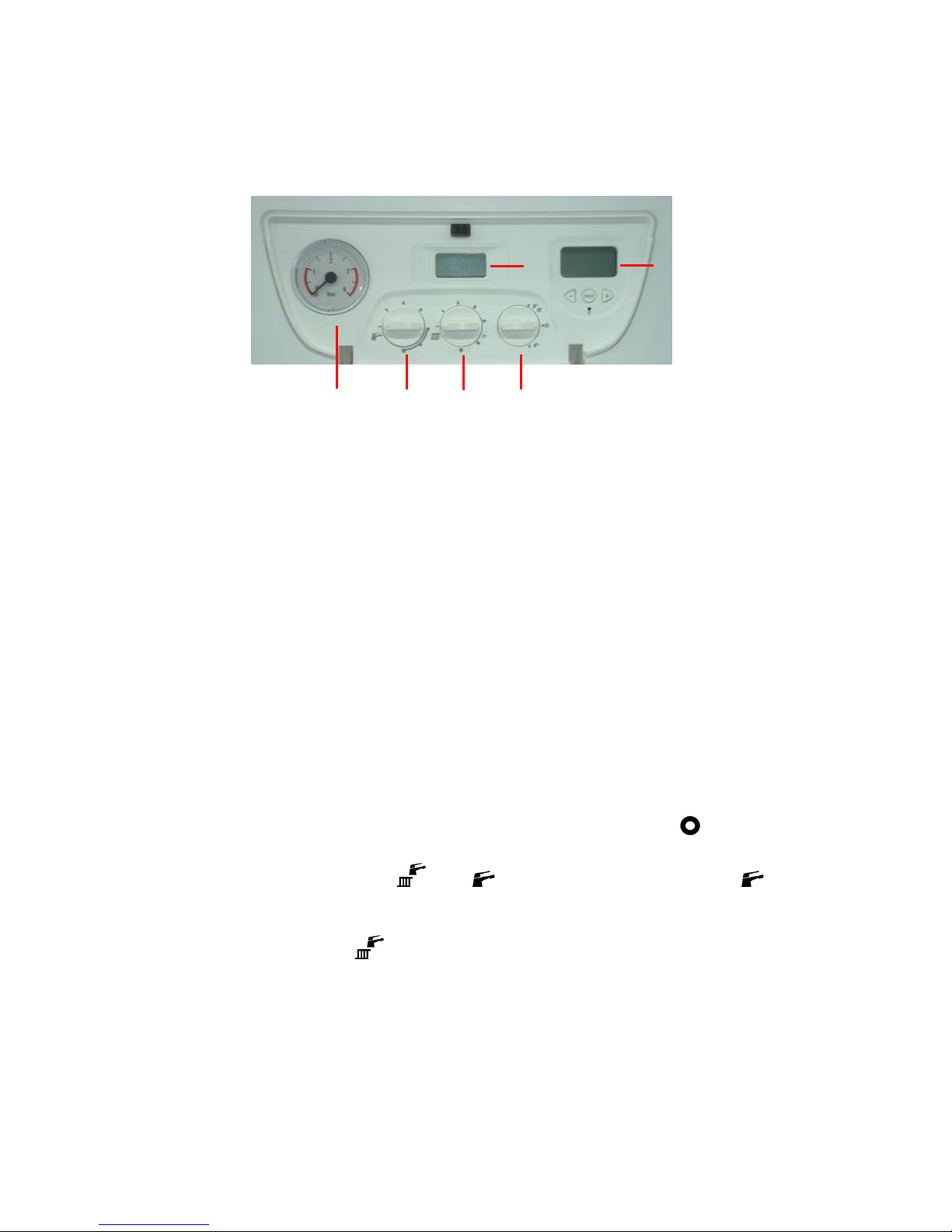
The function and operation of the main controls located on the control panel fascia
(figure 3) is as follows:
1. Pressure Gauge : Shows water pressure in system. Scale between 0 and 4 bar.
Recommended water pressure in system 1.5bar.
2. Domestic Hot Water Temperature Control : The position of this control dial
will determine the temperature of the domestic hot water delivered to the taps or
shower unit. The water temperature can be set from a minimum of 35ºC
(anticlockwise stop position) to a maximum of 60ºC (clockwise stop position.)
3. Central Heating Temperature Control : The position of this control dial will
determine the temperature of the water delivered to the radiators. The water
temperature can be set from a minimum of 30ºC (anticlockwise stop position) to
a maximum of 85ºC (clockwise stop position), unless the boiler is adjusted for
under floor heating operation when the maximum setting is 600C.
4. Function Switch : This is the boilers main operating switch. In the
position
the boiler is in stand-by mode and power supply is ON. For the boiler to operate
the switch must be in the
or position. When switched to the
position the boiler will operate only to supply domestic hot water. (Summer use)
For the boiler to operate to give both central heating and domestic hot water the
switch must be in the
position.(Winter use)
1- C.H. Pressure Gauge 4- Function Switch
2- D.H.W. Temperature Control 5- LCD Display
3- C.H. Temperature Control 6- Electronic Timer
2 3
4
5
6
Figure 3
Page 6
Page 53
1
2
3
4
5
6
7
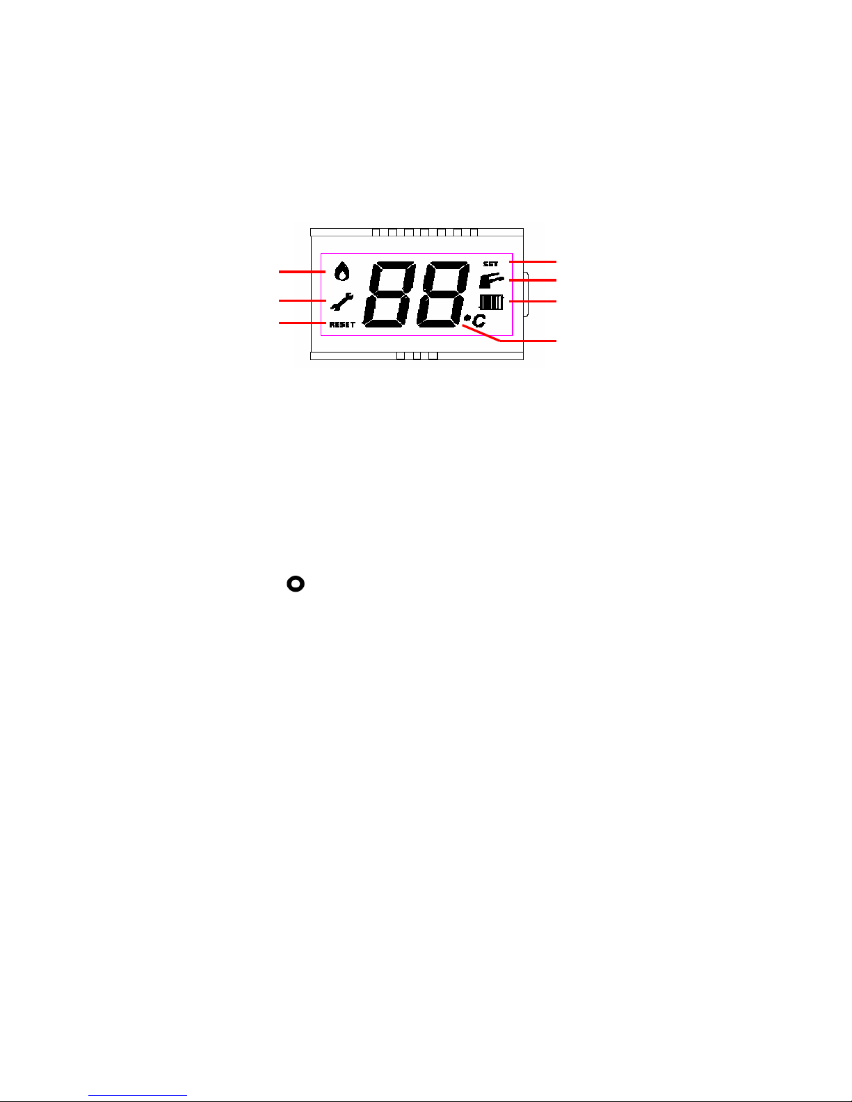
5. LCD Display Screen: While giving the operational status of the boiler and
water temperature, to aid in fault diagnostics the control unit has a built in
facility that automatically indicates a fault status. If more than one fault
simultaneously occurs, then only the highest priority fault is displayed.
(Figure 4)
5.1. Flame indication: When ignition occurs, flame symbol (1) is shown.
5.2. Service Mode symbol : Turn selector control knob (4 figure 3) 3 times
between C/H setting and the off position (no more than 2 seconds between
each turn) the boiler is now in service mode and will stay there for 15mins,
turn both C/H & DHW controls to max, this sets the boiler to max output
and will not modulate, turn both the controls to min to set the boiler on min
without modulation for setting up the default parameters.
5.3. Reset symbol : When reset symbol (3) is showed with fault code, the boiler
will need to be re-set. To re-set the boiler, the function switch must be
switched to position and after 15 seconds back to its previous (summer
or winter) position.
5.4. Set symbol
5.5. Domestic Hot Water Mode : When opening tap, system works at DHW
mode and shows tap symbol
5.6. Central Heating Mode : When selecting winter mode and working at CH
mode, system shows radiator symbol.
5.7. Digits : Digits shows CH,DHW temperature, fault codes etc.
6. Timer : This unit provides to enter burning programme for boiler. Programme can
be programmed according to user demands. Programming timer can be found in
Section 13.5.
FROST PROTECTION
The boiler has a built in frost protection device that protects the boiler from freezing. If
the boiler is to be left and there is a risk of frost, ensure that the gas and electrical
supplies are left connected. The frost protection device will light the boiler when the
Figure 4
Page 7

Page 54
temperature of the boiler water falls below 6oC. When the temperature reaches 15oC, the
boiler will shut down.
Note: This device works irrespective of any room thermostat setting and will protect the
boiler, but not necessarily the full system. Ensure that vulnerable sections of the circuit
are adequately lagged.
SYSTEM PRESSURE
On installation your installer will have filled the boiler and system to its
effective working pressure. The boiler's pressure sensor should be regularly checked on
the LCD to ensure that this pressure is maintained between 1 and 2 bar. If there is a
significant loss in pressure the boiler will lock out. The system may be re-charged by
opening the filling loop to charge the system back up to 1.5bar as indicated on the LCD
panel. DO NOT OVERCHARGE THE BOILER PRESSURE BEYOND 2BAR AS
THE BOILER WILL NOT OPERATE. The filling loop, a flexible hose with two
valves, should be located below the boiler connecting the second pipe on the right to
either one of the outer pipes, see figure 10 on page 19. DO NOT CLOSE ANY OF
THE FOUR SERVICE VALVES.
DIRECTLY CONNECTING TO THE BOILER. If the boiler frequently loses pressure
then your installer should be consulted. Failure to have leakage repaired may cause
corrosion within your heating system.
OPERATING THE BOILER
Prior to operating the boiler, check that the pressure reading, on the LCD panel, lies
between 1 and 2bar.
Set the boiler's 'Central Heating' and 'Domestic Hot Water' temperature controls to
maximum by turning fully clockwise and set the external 'Room Thermostat' (if fitted)
to maximum. (To set the room thermostat refer to its manufacturer's instructions.)
Switch the boiler’s functional switch to the
position. The boiler's integral control
unit will now automatically carry out pre-ignition safety checks before finally igniting
the burner.
The 'Central Heating' and 'Domestic Hot Water' temperature controls and 'Room
Thermostat' can now be set to the desired temperature settings.
When a demand for heat no longer exists, the burner will automatically shut down but
the green 'Boiler Stand by' indicator will remain alight. The boiler will be ready for the
next heating demand.
CLEANING
The boiler casing may be cleaned with a damp cloth followed by a dry cloth to polish.
Do not use abrasive or solvent cleaners.
FURTHER ADVICE
For further advice or information contact Heat Line ™ Service Enquiries by telephone
on 0870 777 8318 in UK and 01 466 4664 in Ireland or e-mail via our web site at
www.heatline.co.uk
 Loading...