

Page 1
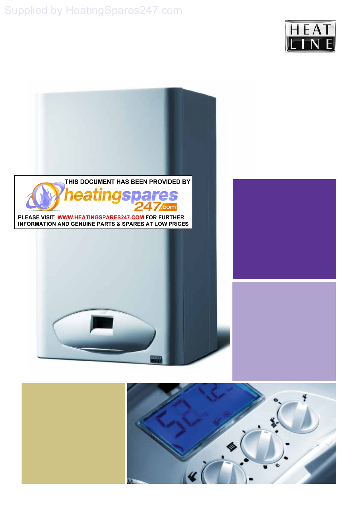
solaris 24PC, 30PC
Supplied by HeatingSpares247.com
solaris
24PC
30PC
Pre-Mix Condensing
Combination Boiler
Installation, Servicing
& User Instructions
Page 2
01
Supplied by HeatingSpares247.com
Natural Gas
Heatline Solaris 24PC/30PC Pre-mix Condensing
Combination Boiler
British Gas Service Listing
Solaris 24PC G.C.No 47-157-04
Solaris 30PC G.C.No 47-157-05
The Heat Line™ range of heating boiler are manufactured
from high quality materials, enabling reliability and
optimum performance.
Heat Line™ are committed to the continual development
of their appliances to ensure their customers benefit from
the latest advances in combustion technology and energy
savings.
Notified Body IMQ 51BP2750
CE Directive 90/396/EEC
CE Directive 92/42/EEC
The manufacturer, in the continuous process to improve
his products, reserves the right to modify the data
expressed in the present documentation at any time and
without prior notice.
The present documentation is an informative support
and it cannot be considered as a contract towards third
parties.
solaris 24PC, 30PC
'Benchmark' Log Book, Boiler Registration & SEDBUK
As part of the industry-wide initiative the boiler comes complete
with an Installation, Commissioning and Service Record Log
Book. Please read the Log book carefully and in accordance with
current legislation, complete all sections relevant to the
appliance and installation. The details within the Log Book will
be required in the event of any warranty work.
On completion the Log Book, which is found on pages 46 & 47
of the Installation manual, must be left with the end user and the
relevant sections completed on each subsequent Service visit.
NOTE: You are also obliged to register the installation of this
boiler with C.O.R.G.I. Should you wish to check the SEDBUK
website for the rating of this boiler, search under DD HEATING
or the boiler name and designation, e.g. SOLARIS 24PC.
For further information or advice (UK) contact
Heatline
TM
:
Service please call:
0870 777 8341
Spares please call:
0870 777 8402
Technical assistance please call:
0870 777 8318
Or by E mail on our Web Site on
www.heatline.co.uk
Page 3
solaris 24PC, 30PC
Supplied by HeatingSpares247.com
02
Contents
Section Page
Preface
1. Installation Regulations 5
2. Technical Data 6
3. Boiler Characteristics 8
4. Operation 8
5. General Installation 9
6. Appliance Siting 11
7. Flue Terminal Location 12
8. Flue (General) 14
9. Electrical Connections 15
10. Boiler Installation 17
11. Gas Supply 19
12. Filling the System 20
13. Control Panel Functions 20
14. Commissioning 22
15. Onboard Adjustments 23
16. Safety Devices 24
17. Routine Servicing 24
18. Component Replacement 27
19. Gas Type Conversion 34
20. Fault Finding Chart 34
Appendices
Appendix 1. Spare Parts List 39
Section Page
User Instructions 40
Page 4
solaris 24PC, 30PC
Supplied by HeatingSpares247.com
03
Preface Warnings
The Heat Line™ Gas fired combination boiler
meets the requirements of Statutory Instrument
'The Boiler (Efficiency) Regulations' and is
deemed to meet the requirements of:
Gas Appliance Directive 90/396/EEC
Efficiency Directive 92/42/EEC
Low Voltage Directive 73/23 EEC
(modified from 93/68) and;
Electromagnetic Compatibility Directive
89/396 EEC (modified from 93/68)
Heat Line™ declares that the materials used in
the manufacturer of this appliance are nonhazardous and that no substances harmful to
health are contained within the appliance.
Heat Line™ accepts no responsibility for the
unsatisfactory performance of the appliance or
flue arising from the failure to comply with the
installation and user instructions. Incorrect
installation could invalidate your guarantee and
may lead to a dangerous situation.
If the appliance is sold on to another customer all
documentation must be passed on and the
appliance re-registered with Heatline in order to
maintain the guarantee.
The boiler must be installed in accordance with
these instructions and the regulations currently in
force. Read these instructions carefully before
installing or using the appliance.
Manual Handling:
As this appliance is heavy it is recommended that
you get assistance when lifting. When
manoeuvring the boiler always use safe techniques
– keep your back straight, bend your knees, don’t
twist, move your feet. Avoid bending forwards or
sideways and keep the load as close to your body
as possible. Where possible transport the boiler
using a suitable trolley, sack truck or get some
assistance. Grip the boiler firmly and before
lifting establish where the weight is concentrated
to determine the centre of gravity, repositioning
yourself if necessary.
Page 5
solaris 24PC, 30PC
230 V
Supplied by HeatingSpares247.com
04
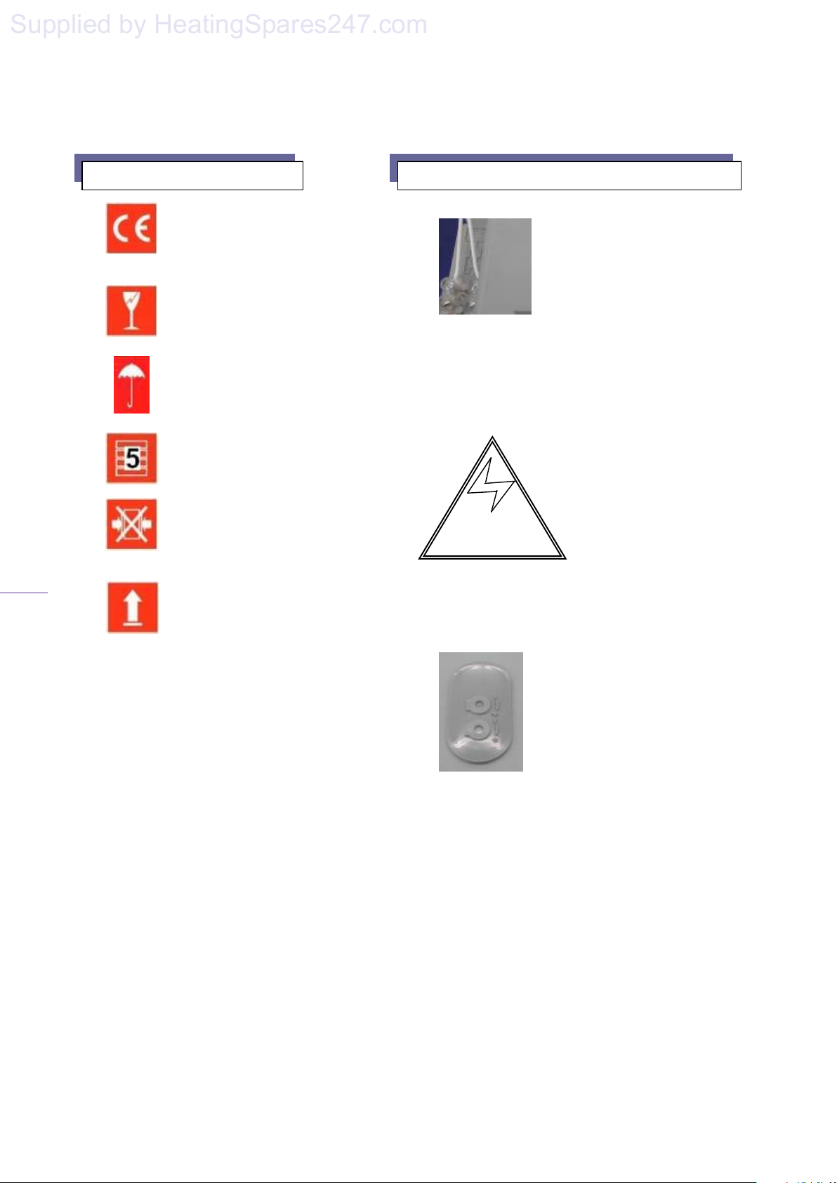
The Signs on Box Access, warnings and connections on the boiler
The sign of approval.
This appliance has been certified
by IMQ
This is a fragile piece of equipment:
Do not drop.
Avoid getting the carton damp or wet
The packed appliances may be
stacked five high.
Do not crush the packaging as this
may damage the appliance.
Store the appliance upright as
indicated on the box.
This picture shows the terminal
block, which is located at the
Room Thermostat bottom left
hand side of the control panel
cover, to which the room
thermostat must be fitted.
NOTE: This is a voltage free connection and no
power must be applied to these terminals. For
mains powered thermostat connection, see section
9.5.
Warning High Voltage!
This sign is located on the
back of the control box
housing warning of high
voltages within the control
box. Turn off and isolate the appliance before
removing this cover. NOTE: Take care as there
may be residual voltage within some components.
Potentiometer cover: Removal of
the cover, which is found on the
back of the control box, gives
access to the adjustment
potentiometers. NOTE: Do not
make any adjustments without
reading the instructions carefully.
Page 6

05
Supplied by HeatingSpares247.com
1. Installation Regulations
1.1. This appliance must be installed by a
competent person as defined by the Gas
Safety (Installation and Use) Regulations.
Failure to install this appliance correctly
may invalidate your guarantee and may
lead to a dangerous situation.
1.2. Your C.O.R.G.I. registered engineer
should carry a C.O.R.G.I. ID card
containing their registration number,
which should be recorded in your
BENCHMARK Log Book, which is
supplied with the Instructions. You can
check the validity of this ID number by
contacting C.O.R.G.I. on 0870 401 2300.
1.3. This appliance must be installed in
accordance with the Gas (Safety and Use)
Regulations, current Building
Regulations, Building Standards
(Scotland), I.S.813 Installation of Gas
Appliances (Ireland), IEE Wiring
Regulations (BS 7671), Health and Safety
Document No. 635 (Electricity at Work
Regulations) and Local Water Authority
Bye Laws.
1.4. On installation the following British
Standards must also be considered:
BS 6798 Specification for installation
of gas fired hot water boilers of rated
input not exceeding 70kW.
BS 5449 Central heating for Domestic
Premises.
BS 5546 Installation of gas hot water
supplies for domestic purposes.
BS 5440 Flues and Ventilation for gas
appliances of rated input not exceeding
70kW (Part 1 Flues)
BS 5440 Flues and Ventilation for gas
appliances of rated input not exceeding
70kW (Part 2 Air Supply)
BS 6891 Installation of low pressure
gas pipe-work installations up to
28mm (RI).
Reference should also be made to British
Gas Guidance Notes for Installation of
Domestic Gas Fired Boilers.
1.5. Due to the manufacturer’s continuous
improvement policy the manufacturer
solaris 24PC, 30PC
reserves the right to change any specification
of the appliance or make modifications to
these instructions, which meet current
regulations at the time of print. However, the
instructions must not be taken as overriding
statutory requirements.
1.6. To ensure reliability and continued
performance ensure that other components in
the system are also approved to relevant
standards and that the appliance and system is
adequately protected and maintained on an
annual basis.
1.7. Your boiler comes with a statutory 1 year
guarantee. In order to claim your 2
nd
years
free warranty you must completes and return
your guarantee card within one month of the
date of installation or ring the telephone
number on the label on the front of your
appliance.
Note: Your second year of warranty is only
valid if there is evidence of service after the
first year of installation. It is recommended
that the appliance be serviced annually by a
competent person, as defined in the Gas
(Safety and Use) Regulations, and the service
record maintained in the Benchmark
Logbook.
For further information or advice (UK) contact
Heatline
TM
:
Service please call: 0870 777 8341
Spares please call: 0870 777 8402
Technical assistance please call: 0870 777 8318
or
E–mail via our web site www.heatline.co.uk
.
Page 7
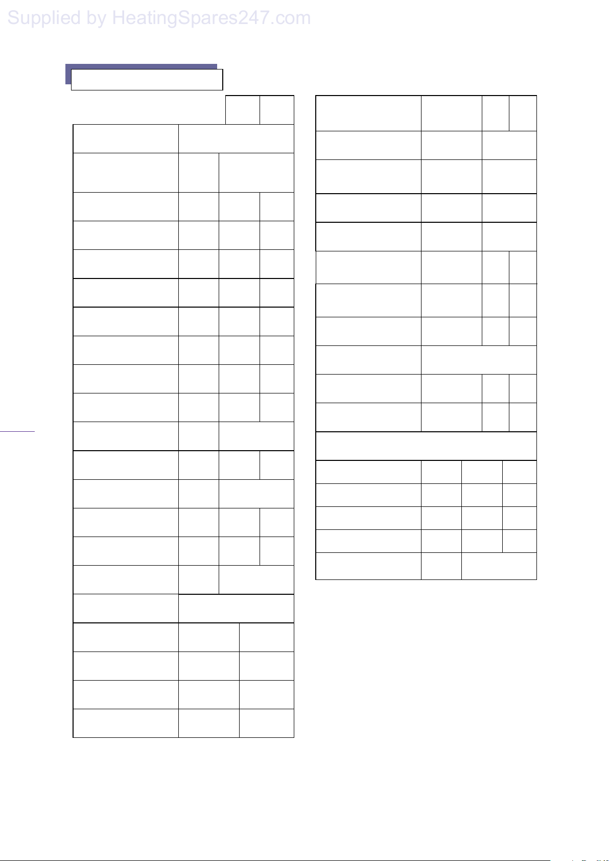
2. Technical Data
Supplied by HeatingSpares247.com
solaris 24PC, 30PC
06
Gas Category
Gas inlet pressure G20
Heat Input (Q
Heat Output (P
Heat Input (Q
Heat Output (P
Heat Input (Q
Heat Output (P
Useful efficiency at
100% load
Useful efficiency at 30%
Inlet Pressure
(Natural Gas)
Gas Rate (Natural Gas)
Power supply
max
max
max
max
) (CH/DHW)
min
) (CH/DHW)
min
load
) (CH)
) (CH)
) (DHW)
) (DHW)
24PC 30PC
II
2H3+
mbar 20
kW
(Btu/h)
kW
(Btu/h)
kW
(Btu/h)
kW
(Btu/h)
kW
(Btu/h)
kW
(Btu/h)
25.03 30.5
24.42 29.8
31.05 35.8
30.3 35.01
9.26 10.00
9.35 10.09
% 97.6 97.8
% 107.4 107.5
mbar 20
m³/h
Input
Max
2.65
230 V
50 Hz
Max
3.2
Domestic Water Supply
Output (liters/min.)
Expansion Vessel
Expansion Vessel
Flue Extraction
CO2 % at max. input
±0.1%
Nitrogen oxide (NOx)
emissions at max. input
Class 5)
(NO
x
Nitrogen oxide (NOx)
emissions at max. input
Class 5)
(NO
x
Combustion products
temperature (max.)
Case Dimensions (mm)
Shipping weight
Dry weight
G30/G31 VERSION
Gas Inlet Pressure
Gas Diaphragm
35 oC ∆T
o
C ∆T
30
o
C ∆T
25
12.20
14.24
17.08
Capacity
(litres)
Pre-Charge
(bar)
Diameter
(mm)
0·5
60/100
ppm 9
ppm 20.6 22
ppm 22.6 26
o
C 70 72
330d x 430w x 720h
kg 44 45
kg 41 42
mbar
28-30/37
mm 4.70 5.35
14.35
16.73
20.10
7
28-
30/37
Gas Diaphragm
Air Diaphragm
Max. power
consumption
Level of protection
Maximum heating
temperature
Max. domestic hot water
temperature
Operating pressure
(Bar)
Domestic water supply
pressure (Bar)
mm 6.5 7.0
colour Red Red
Watts
140
IPX4D
ºC
85º
ºC 64º
PMS
(Min)
PMS
(Min)
3
(0·8)
8
(0·25)
Air Diaphragm
Gas rate (LPG)
CO2 % at min. input
±0.1%
colour Orange Red
kg/h 1.29 1.52
10
Page 8
solaris 24PC, 30PC
6
10
2
1
16
23
11
17
Supplied by HeatingSpares247.com
07
24
22
21
20
19
18
15
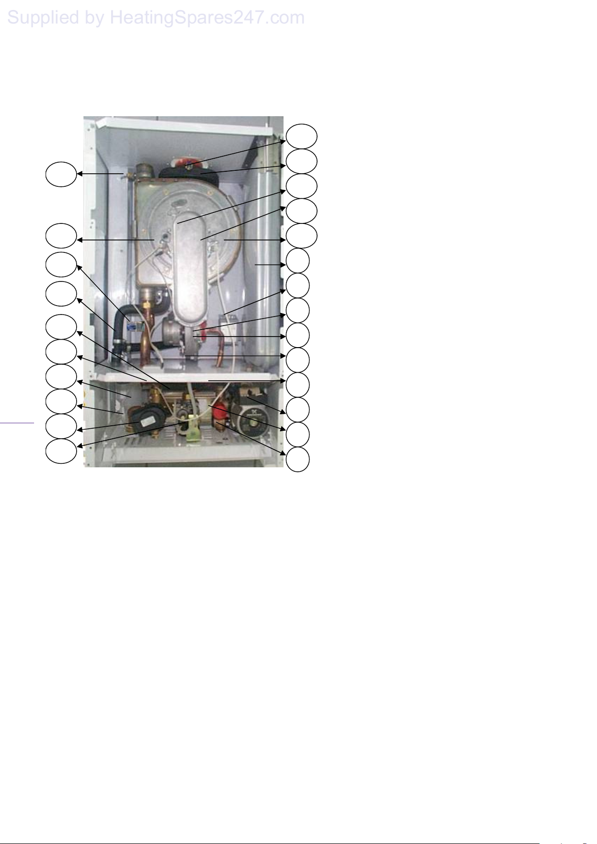
Figure 1
A B C D E
14
13
12
9
8
7
5
4
3
1 - D.H.W. Flow Sensor
2 - Water Pressure Sensor
3 -Pump
4 - Pressure Relief Valve
5 - Fan
6 - Air/gas mixer
7 - Air/gas mixer ring
8 - Supply transformer
9 - Expansion Vessel
10- Heat exchanger
11 - Ionisation electrode
12 - Burner
13 - Plastic flue duct
14 - Plastic flue safety thermostat
15 - Gas valve
16 - Diverter Valve
17 - DHW temperature sensor
18 - Condensate trap
19 - Overheat Safety thermostat
20 - Secondary Heat Exchanger
21 - Condensate drain pipe
22 - Central heating temperature sensor
23 - Ignition electrode
24 - Manual air vent
A - Heating Flow (22mm)
B - D.H.W. Outlet (15mm)
C - Gas Inlet (22mm)
D - Cold Water Inlet (15mm)
E - Heating Return (22mm)
Page 9
3. Boiler Characteristics.
Supplied by HeatingSpares247.com
solaris 24PC, 30PC
08
3.1 The Heat Line boiler is a fan flued, wallmounted combination boiler that supplies both
central heating and mains fed domestic hot
water. Being room sealed the boiler may be
installed in any room without the need for
purpose made ventilation. However, if the
boiler is installed in a compartment it is
recommended that the compartment is
ventilated for cooling purposes. A functional
diagram of the boiler’s principal components
is given in figure 1, page 7.
3.2 An electronic control unit, consisting of a
PCB which includes ignition module provides
direct burner ignition and flame supervision
along with continuous modulation of the
burner’s gas supply.
3.3 An interface unit, which includes boiler
adjustment potentiometers and fault display
codes provides easy serviceability of the
boiler.
3.4 Heat transfer to the boiler’s primary
hydraulic circuit is obtained via a primary, gas
to water heat exchanger contained within a
hermetically sealed combustion chamber. A 24
volt, modulated speed fan blows the products
of combustion from the combustion chamber
to outside air via an associated flue system.
3.5 A secondary heat exchanger allows the
instantaneous transferral of heat from the
primary hydraulic circuit to water destined for
domestic hot water use. The secondary heat
exchanger is sized so as to minimise thermal
shock and is protected against the build up of
lime scale by limiting the D.H.W. outlet water
temperature to a maximum of 60°C.
3.6 An integral pump located in the boilers
main hydraulic circuit circulates water through
the primary heat exchanger to either the
central heating circuit or D.H.W. heat
exchanger, depending on the demand. In the
event of reduced or interrupted water
circulation in the central heating circuit, a
system by-pass should be fitted, in accordance
with current legislation as far away from the
boiler as possible. Note: It is no longer
permissible to utilise a non-thermostatic controlled
radiator as a by-pass.
3.7 Room temperature can be controlled by the
use of an external room thermostat or temperature
regulator. Note connection of the room thermostat
is dependant on the operating voltage of the
thermostat. See section 9.4 & 9.5 for details.
3.8 The C H system temperature can be adjusted
automatically to balance heat demand, dependant
on the outside temperature, if an outdoor sensor is
connected directly to the main PCB. Call Heatline
Technical Services for further assistance.
3.9 The boiler incorporates an integrated clock,
which allows the setting of central heating periods
and the boiler’s control panel incorporates an LCD
display, which indicates the state of operation and
fault defect codes.
4. Operation
4.1 Using the operating switch the boiler can be
set to operate either on domestic hot water
only or domestic hot water and heating.
Note: Domestic hot water demand draws
preference over heating. During heating
periods the boiler will automatically revert
back to heating mode, after a draw off of hot
water, but there will be a 45sec delay if the
No.3 dipswitch is set to the OFF position.
See fig 19 page 27.
4.2 Depending on demand water is either diverted
via the three port valve to the secondary waterto-water heat exchanger for domestic hot
water or directly to the heating system.
4.3 DOMESTIC HOT WATER MODE:
On opening a hot water faucet the boiler
automatically responds to fire the boiler and
supply the water-to-water heat exchanger with
hot water via the three port valve, located on
the hydro-block. The boilers electronic
control unit automatically modulate the
burner’s output to maintain the required
temperature at the faucet. Hot water will
Page 8
Page 10
solaris 24PC, 30PC
Supplied by HeatingSpares247.com
09
continue to flow until the faucet is closed
and the boiler automatically shuts down.
Note that the pump will continue to run for
a further 10secs to dissipate the residual
heat from the boiler.
4.4 DOMESTIC HOT WATER AND
CENTRAL HEATING MODE:
When heating demand is required, i.e. the
timer and thermostat are calling for heat,
then providing the power is on the boiler
will fire automatically. An integral pump
is then energised and hot water from the
boilers primary circuit is circulated around
the central heating systems pipe-work and
radiators. When the demand for central
heating is no longer present, either the
thermostat reaches temperature or the time
clock reaches the end of its set period, the
burner will shut down and the boiler will
revert to stand-by, waiting to respond to
the next heating or hot water demand. The
pump will continue to operate for a short
period of time to dissipate any excess heat
from within the boiler’s heat-exchanger.
If during the heating period there is a call
for hot water this will take preference over
heating. When satisfied the boiler will
then supply the heating demand as
required. Note there may be a 45sec delay
depending on how the boilers dipswitches
are set. See section 14.3 for details.
5. General Installation
5.1 Installer Testing & Commissioning
Tips
• The installer shall instruct the user in the
operation of the boiler, safety devices
contained within the boiler and instruction
on how to re-pressurise the system if the
water pressure falls. The installer should
then hand over the instructions and
completed Benchmark Logbook.
• The user should be instructed to keep the
instructions and logbook in a safe place for
servicing and future reference.
• It is important to keep the boiler clear of dust
during the installation. In particular, do not
allow debris to enter the top of the boiler where
the flue connection is made. This may cause the
fan outlet to get blocked or combustion
chamber to fill with debris and will, of course,
cause the boiler to fail to ignite on first ignition.
It is recommended that you check the fan outlet
before you light the boiler.
• Before you fit the boiler ensure that the pipe
work that you are installing is connected to the
appropriate connections on the boiler i.e. cold
water pipe to cold water inlet, hot water outlet
to the hot water tap etc.
• Because the boiler is actually operated, at the
end of each production stage, a small amount
of water is retained within the boiler when
packed. Please ensure that you spin the pump
rotor manually before firing the boiler.
• Remember to thoroughly flush the water
circuits in order to remove any fluxes and
debris from them. This should be done
particularly where boilers are being fitted to
existing radiator circuits.
• Refer to BS 7593:1992 for the details to clean
DHW and Central heating system.
• This boiler has been factory set and does not
require any adjustments to the gas valve or
fan speed.
• Remember to release the small cap, 1 turn, on
top of the automatic air vent, located on top of
the pump, before filling. This will ensure that
air is vented from the pump as the system fills.
• Do not use the pressure relief valve as a
means of flushing the system, please use the
valve below the pump. Discharging water from
the system via the pressure relief valve may
leave debris on the valve seat allowing water to
seep after you have left the job. This will cause
the boiler to lose pressure and the boiler to
lockout.
• The boiler is fitted with inlet filters both on the
cold water inlet and the central heating return.
If you are unable to obtain hot water at the
faucet it is likely that the cold water inlet valve
filter has become blocked, whilst blockage of
the filter on central heating return valve will
cause the heater to lock out at the overheat
thermostat as the water flow is reduced.
Page 9
Page 11
solaris 24PC, 30PC
Flow
control
valve
Bypass
valve
Filling
device
Cold water
Domestic
water
Heating outlet
control
valve
low
valve
Additional
expansion
vessel (if
Supplied by HeatingSpares247.com
10
• If you are able to obtain hot water but not
heating it is also advisable to check the
clock connections and that the room
thermostat and time clock are calling for
heat.
• Remember that after hot water draw off
there is a 45 sec delay before the heating
will fire up if No.3 dipswitch is in the OFF
position, see fig 19 on page 27.
• When commissioning the boiler check the
inlet pressure is at 20mbar and burner
pressure against the Technical data on page
6.
• Note an anti-cycle delay time can be set up
to a maximum of 255 seconds by adjusting
potentiometer 2 as described in section 15.4
on page 27.
If you experience any problems please refer to
the installation and commissioning guidelines
within the boiler instruction manual. If
necessary, please contact Heat Line
TM
Enquiries:
For further information or advice (UK) contact
Heatlin
TM
:
Service please call:
0870 777 8341
Spares please call:
0870 777 8402
Technical assistance please call:
0870 777 8318NOTE – FOR
INSTALLERS:
REMEMBER IT IS A LEGAL
REQUIREMENT TO COMPLETE THE
BENCHMARK CODE OF PRACTICE
LOGBOOK BEFORE LEAVING THE
INSTALLATION.
5.2 The boiler is designed to operate on fully
pumped, pressurised sealed systems operating at a
maximum of 3bar pressure and maximum design
flow temperature of 85
0
C.
5.3 The boiler’s integral expansion vessel is precharged to a pressure of 0.5bar and will
accommodate a system volume of 125l at an
average water temperature of 75
0
C and maximum
system pressure of 3bar. If the system volume is
more than 125l an additional expansion vessel
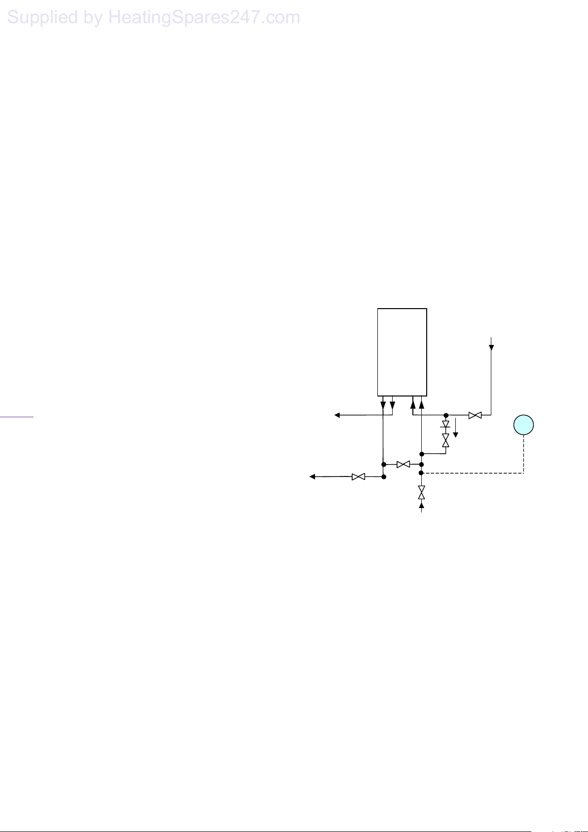
must be fitted to suit the size of the system. A
typical installation of an additional pressure vessel
Figure 2 – Note the filter valve supplied should
is shown below in figure 2 below.
be fitted to the heating return pipe, which is on
the extreme rightof the boiler as shown below.
Boiler
F
control
hot
Flow
Heating return
5.4 The heating circuit should be designed and
balanced to give a 20
0
C temperature rise across
the boiler flow and return.
5.5 When fitting a new boiler to an existing
system the system must be thoroughly flushed in
accordance with the recommendations of BS7593
prior to installation.
5.6 It is recommended that the system should be
protected by an anticorrosion inhibitor.
5.7 On installation it is important to ensure that
the heat exchanger is not a natural collection point
supply
required)
Page 10
Page 12
solaris 24PC, 30PC
Supplied by HeatingSpares247.com
11
for air and where possible, the system pipe
work should have a gradient to ensure any
excess air is carried naturally to other purpose
made, air release points.
5.8 The system’s water must always be
allowed to circulate whenever the circulation
pump is running. A return by-pass must be
provided.
NOTE – It is no longer permissible to use
non-thermostatic radiator valves to allow
by-pass through a radiator.
5.9 In high water volume systems or under
floor heating systems where prolonged
operation of the boiler is expected at
temperatures below 60
0
C, a by-pass must be
installed on the boiler outlet in order to
prevent condensation forming inside the boiler
body. Failure to comply with this requirement
will invalidate the manufacturer’s guarantee.
5.10 The pressure relief discharge must be
directed away from any electrical equipment
or where it could cause a hazardous situation
and terminated in a safe but visible position.
5.11 To enable adequate drainage of the
system drain cocks compliant with BS2879
must be fitted at the lowest points in the
system pipe-work.
5.12 To obtain the best hot water performance
from your boiler it is suggested that the cold
water supply to the boiler is taken directly
from the incoming mains water supply.
Note that the boiler will not operate unless
there is a minimum pressure of 0.25bar with a
flow rate of 2.5l/min. Where inlet pressures
exceed 8bar, a pressure regulator must be
fitted to the cold water supply.
5.13 Where cold water mains are fitted with a
water meter, check valve(s) or loose jumper
stopcock it is recommended that a domestic
hot water mini-expansion vessel may need to
be fitted.
5.14 Although the boiler is designed to inhibit the
formation of scale, in hard water areas above
200mg/l, a proprietary scale reduced should be
fitted in the cold water supply to the boiler.
5.15 To obtain the best hot water performance
from your boiler it is suggested that supplies to
faucets are run in 15mm copper, as short as
possible and where practical, be insulated to
reduce heat loss.
5.16 The boiler incorporates a frost protection
thermostat. Therefore if the boiler will not be
used for long periods of time during cold weather,
in order to avoid freezing the electric supply must
be left ON and all the central heating isolation
valves must be left open. The internal frost
thermostat will then operate the boiler if the
temperature falls too low. However, if the
electrical supply is to be turned off the boiler, the
heating system and domestic hot water circuit
must be drained.
6. Appliance Sitting
If the boiler is to be installed in any room or
6.1
compartment, it requires no purpose made
ventilation for combustion air. If sited in a room
containing a bath or shower then particular
reference is drawn to the current I.E.E. Wiring
Regulations and local Building Regulations.
.
6.2 The boiler is not suitable for external
installation unless protected by a purpose made
building such as a boiler house.
6.3. The following clearances are recommended
for installation purposes; 200mm above, 300mm
below and 20mm at each side. 600mm is required
at the front but this may be upon opening a
cupboard door.
6.4 The boiler must be sited at least 1m away from
flammable materials and combustible walls must
be protected with appropriate insulation.
.
6.5 The wall on which the boiler is mounted must
be sufficiently strong enough to support the
weight of the boiler.
Page 11
Page 13
solaris 24PC, 30PC
7. Flue Terminal Location
Supplied by HeatingSpares247.com
12
6.6 A condensate drain pipe must be fitted to
allow discharge of condensate to a drain or
soakway. Note condensate is acidic and
should be discharged through plastic or
suitable corrosion resistant pipes.
Where possible condensate should be
discharged into the household internal
drainage system. If this is not practical,
discharge can be made into an external drain.
If neither of the above options are possible
then condensate must be discharged into a
purpose designed soakway.
It is recommended that any external
condensate pipe is insulated and increased
to 32mm diameter in order to prevent the
condensate from freezing.
6.7 For compartment installation the
requirements of BS6798 and BS5440: Part 2
must be met.
The compartment must be of sufficient
size to permit access for inspection and
servicing or the removal of the boiler and
any ancillary equipment.
Any space used for airing clothes or
storage must be separated from the
appliance by a non-combustible partition.
Where the partition is formed from
perforated material, then the major
dimension of the apertures shall not exceed
13mm.
No combustible surface must be within
20mm of the boiler casing without
protection.
There must be 20mm clearance between
the compartment door and boiler case.
Where the boiler’s flue pipe passes
through the airing space, it must be
protected by a non-combustible sleeve or
fire stop having a minimum clearance of
20 mm between the flue pipe and sleeve.
In addition, if the flue pipe passes through
the partition then the clearance gap of the
flue pipe or its guard with the partition
must not exceed 13 mm.
6.8 When the boiler is intended for use with
LPG it must not be installed in a room or
internal space below ground level.
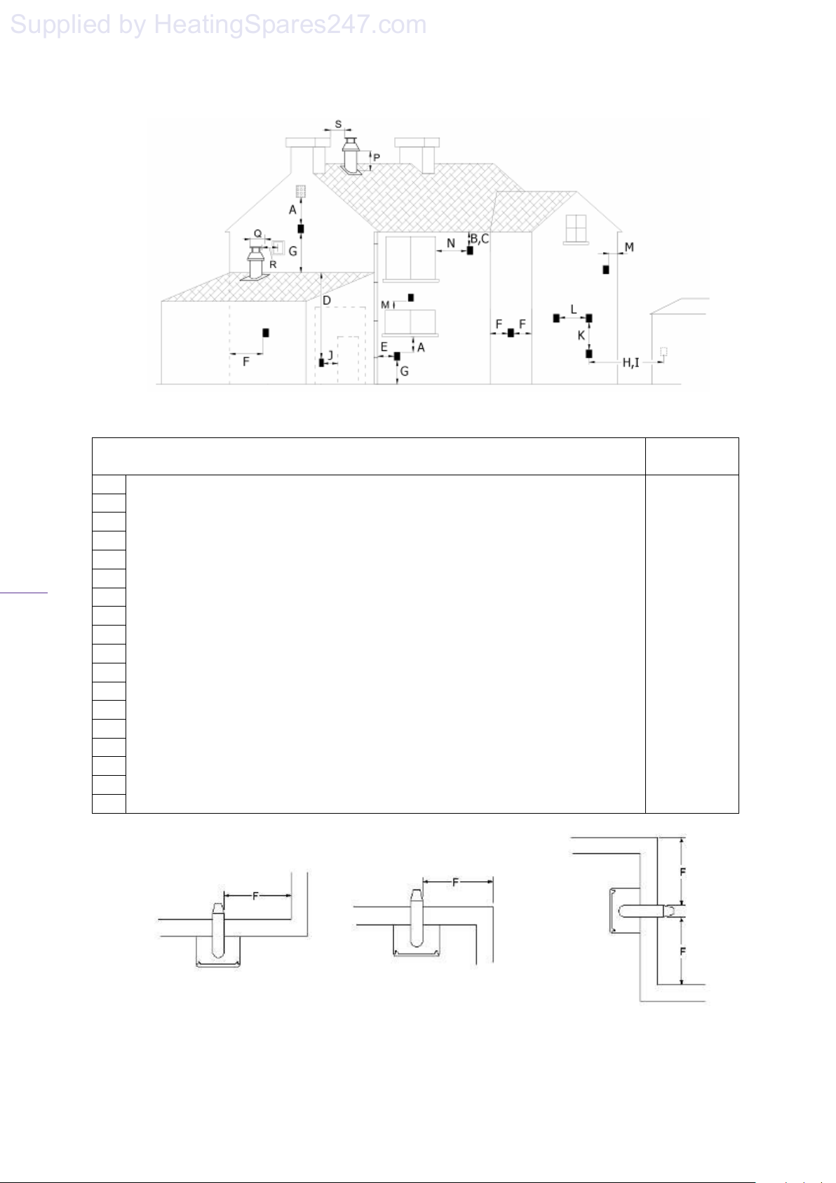
7.1 The flue terminal must be sited with minimum
clearances as specified in Figure 3. Note if
pluming becomes problematic or causes a
nuisance a plume management kit is available
from your stockist.
.
7.2 Current regulations and standards require a
terminal guard to be fitted where the terminal is
accessible to touch or at risk of being damaged.
All wall mounted terminals sited within 2m of the
level which people have normal access, should be
adequately protected with a suitably sited guard
7.3 Where the flue terminates within 1m of a
plastic or painted gutter or within 500mm of
painted eaves then protection should be provided
in the form of an aluminium shield at least 1m in
length, fitted to the underside of the gutter or
painted surface.
7.4 The flue should not be sited where the
condensate “plume” may give rise to a nuisance
factor under certain weather conditions.
NOTE: If you have difficulty siting the flue in
an appropriate location your supplier will be
happy to supply a “anti-plume management
kit”, which discharges the flue products at a
higher level or a deflection elbow, which
deflects the plume to the left or right.
Page 12
Page 14
13
Supplied by HeatingSpares247.com
solaris 24PC, 30PC
Figure 3
TERMINAL POSITION MINIMUM
A- Directly below an openable window or other opening e.g. air brick 300 mm
B- Below gutters, soil pipes or drain pipes 75 mm
C- Below eaves 200 mm
D- Below balconies or car front roofs 200 mm
E- From vertical drain pipes and soil pipes 150 mm
F- From internal or external corners 300 mm
G- Above ground, roof or balcony level 300 mm
H- From a surface facing a terminal 600 mm
I- From a terminal discharging towards another terminal 1200 mm
J- From an opening in a car port (e.g. door, window) into a dwelling 1200 mm
K- Vertically from a terminal on the same wall 1500 mm
L- Horizontally from a terminal on the same wall 300 mm
M- Above an opening, air brick, opening windows, etc. 300 mm
N- Horizontally to an opening, air brick, opening windows, etc. 300 mm
P- Above roof level (to base of terminal) 300 mm
Q- From adjacent wall to flue 300 mm
R- From an adjacent opening window 1000 mm
S- From another roof terminal 600 mm
DISTANCE
Internal Corner
External Corner
Page 13
Double Corners
Page 15
8. Flue (General)
A DANGEROUS SITUATION.
Supplied by HeatingSpares247.com
solaris 24PC, 30PC
14
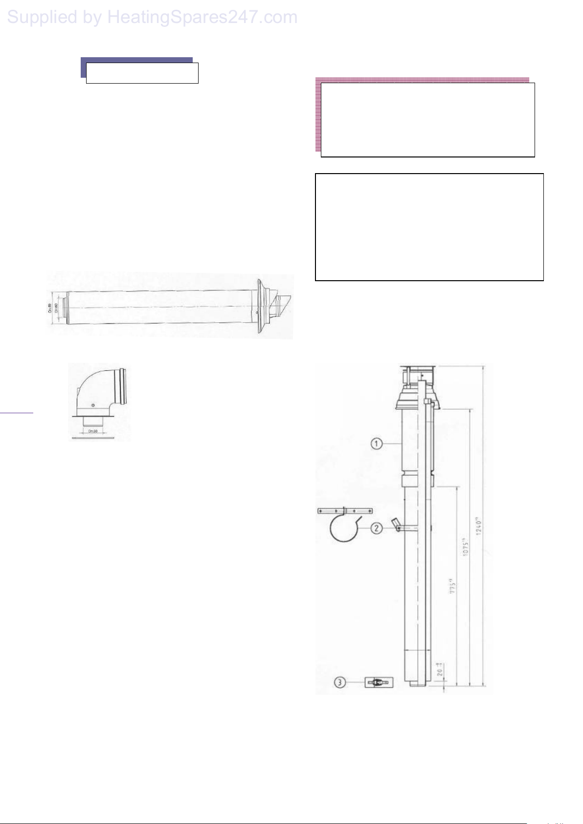
8.1 The boiler utilises a concentric flue
arrangement which consists of a 60mmdiameter inner flue and 100mm-diameter outer
air inlet duct.
8.2. A standard 700+/-5mm flue kit (figure 4)
is supplied with the boiler, which can be
routed to the rear, left or right of the appliance
by means of a 90
0
degree bend (figure 5). The
bend is connected to the boiler using the
screws provided and sealed with the gasket.
Figure 4
Figure 5
8.3. The horizontal 60/100cm flue pipes may
be extended up to a maximum of 7m using
additional spare components available from
your supplier.
8.4. A vertical 60/100cm flue kit is also
available (figures 6a & 6b) from your supplier
up to a maximum length of 8m. The terminal
is suitable for a flat or pitched roof.
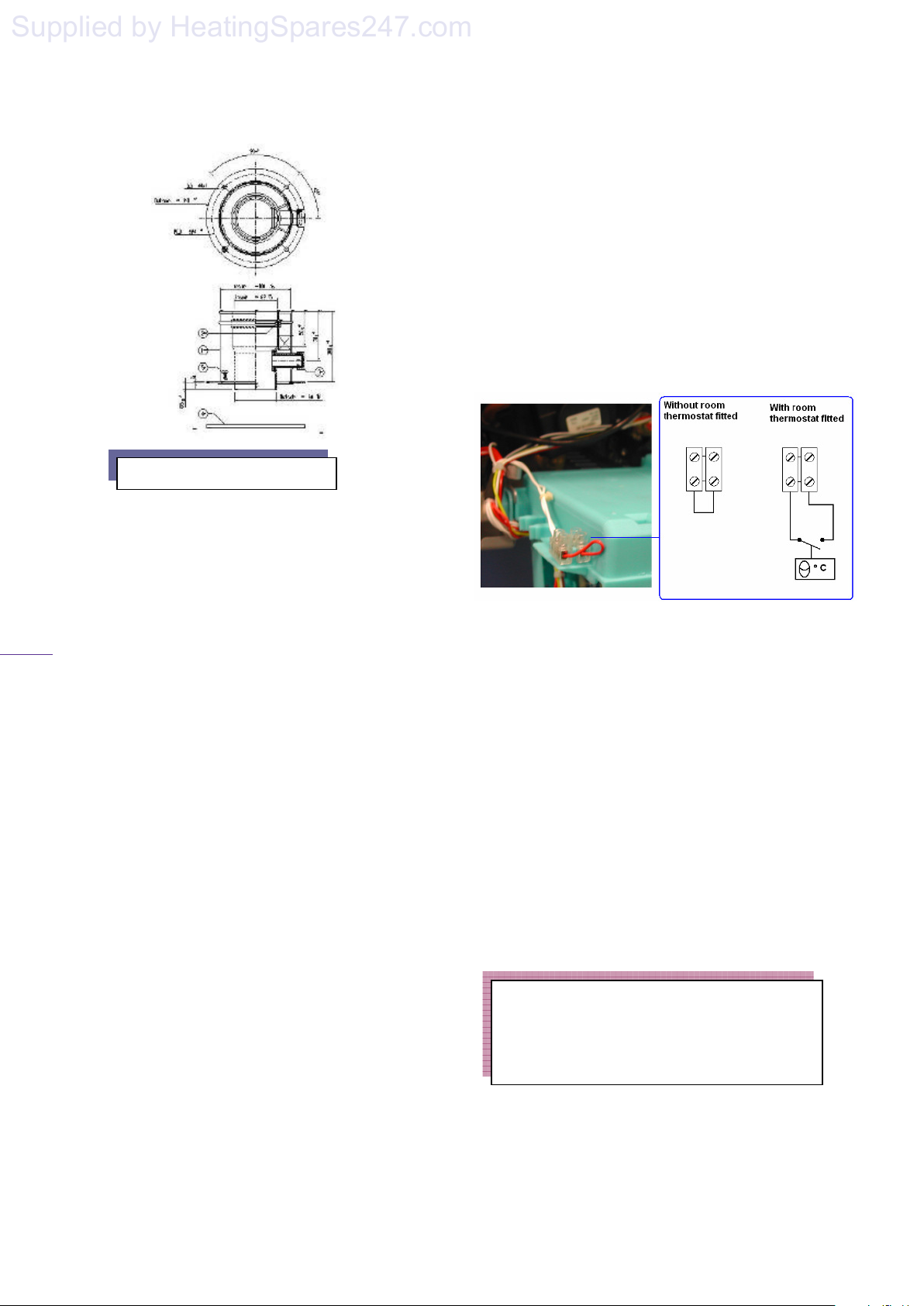
8.6. The connection of the vertical flue system
is similar to the Horizontal flue connection.
However, the 80/125 system is connected with
screws to the boiler and the vertical extension
pipes and roof terminal are connected by clips
as shown in figure 6b, item 3.
Note. For each additional 90º elbow used the
maximum flue length must be reduced by 1.5
m, whilst the use of 2 x 45º bends warrants a
reduction of 2m.
ONLY A HEATLINE APPROVED FLUE IS
TO BE USED WITH THIS PRODUCT.
FAILURE TO COMPLY WITH THIS
REQUIREMENT WILL INVALIDATE
YOUR GUARANTEE AND MAY LEAD TO
WARNING!
6a
Page 14
Page 16
15
Supplied by HeatingSpares247.com
Figure 6b
9. Electrical Connections
9.1 The boiler is supplied factory wired
complete with 1.5 m of mains fly lead. All
electrical connections to the mains supply
must be made in accordance with the current
I.E.E. regulations.
9.2 The boiler must be connected to an
effective earth system. Using the cable
supplied the boiler may be connected via a 5
amp fused three pin plug to an unswitched
shuttered socket outlet. However if the boiler
is installed in a room containing a bath or
shower regulations dictate that disconnection
must be incorporated in the fixed wiring with a
switch provided for disconnection from the
mains supply having a contact separation of at
least 3 mm on all poles and fused at 5 amp.
9.3 The point of connection must be readily
accessible, at a distance no further than 1.5m
adjacent to the appliance and provide complete
electrical isolation for the boiler and control
system.
9.4 The low voltage room thermostat terminal
block is located on the back left side of the
control box (figure 7). On connection of a
voltage free room thermostat to the boiler, the
factory fitted bridge across the room
thermostat terminal connectors must be
removed. If a mains voltage thermostat is to
be used the please refer to figure 8.
solaris 24PC, 30PC
9.5 Mains powered thermostats must be connected
directly to the mains circuit board as indicated in
Figure 8.
9.6 Ensure that the polarity of the mains
connection is correct as reversed polarity may
cause the appliance to malfunction.
9.7 While the boiler's main PCB, pump, three-way
valve and gas valve are supplied at 230V a.c., all
other components and associated circuits are
supplied at low voltage.
9.8 On connecting the mains electrical supply to
the boiler, it is essential to ensure that electrical
safety checks for earth continuity, earth resistance,
polarity and short circuit are carried out prior to
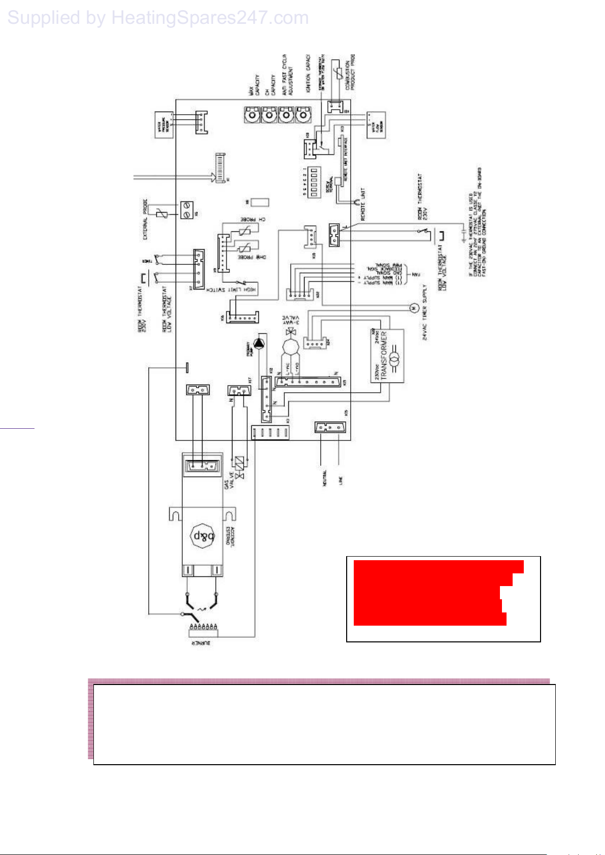
making the final connection. A diagram of the
boiler's electrical circuit is given in figure 8.
9.9 Fuse Ratings
F1 and F2 are 3.15A fast
Bertelli & Partners Circuit Board
F1 – 3.15A fast
F2 – 3.15A fast
F3 – 3.15A fast
SIT Circuit Board not used
F1 – not used
F2 – not used
Warning: On no account must any
external voltage be applied to any of the
terminals on the heating control
connection plug.
Page 15
Page 17
solaris 24PC, 30PC
Supplied by HeatingSpares247.com
16
Important Note.
Connection to the mains electrical supply must be maintained at all times in order to provide
domestic hot water, frost protection, anti seizure protection of the pump and pump over-run
facility. Ensure that the boilers electrical supply is not interrupted by any external controls.
This diagram is illegible and requires
that the thermostat connections are
clearly marked showing the live
terminal of the mains thermostat
connection clearly differenciated.
Page 16
Page 18
17
Supplied by HeatingSpares247.com
10. Boiler Installation
10.1 Manual Handling: This appliance is
heavy and it is suggested that it should be
lifted by two people. When manoeuvring the
boiler always use safe techniques truck if
possible and obtain assistance if required –
when lifting keep your back straight, bend
your knees, don’t twist, move your feet. Avoid
bending forwards or sideways and keep the
load as close to your body as possible. Where
possible transport the boiler using a suitable
trolley, sack truck or get some assistance.
Grip the boiler firmly and before lifting
establish where the weight is concentrated to
determine the centre of gravity, repositioning
yourself if necessary.
To remove the appliance:
1. Carefully slit or remove the sealing tape
being careful not to scratch the appliance
door.
2. Fully open the carton lid and remove the
condensate hose and mounting bracket.
3. Roll the carton onto its open face.
4. Lift the carton free of the inner packaging.
5. Remove and valve package and
instructions.
6. Stand the boiler on its base within the
styrene block and remove the top
packaging piece.
7. If you wish to remove the styrene base lie
the appliance on its back to do so.
8. Read the instructions carefully before
installation of the appliance.
10.2 Prior to installing the boiler check the
contents of the carton: Appliance, Valves,
Condensate hose, Wall Hanging Bracket,
Mounting Template, Service, Installation and
User Manual, which includes the Benchmark
Log Book, and Guarantee Card. The boiler
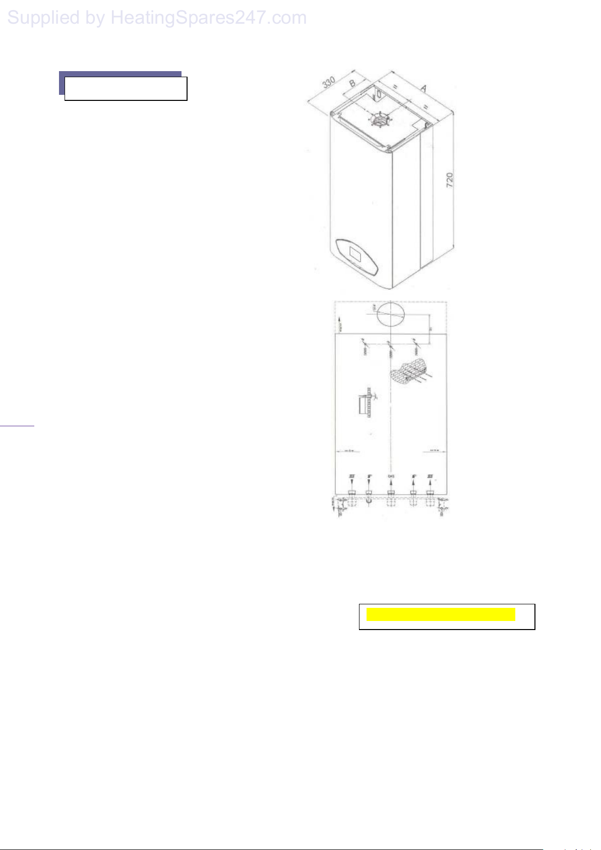
dimensions are given in figure 9.
Fixing Jig (Optional)
Give dimensions between valves
solaris 24PC, 30PC
Figure 9
A: 430 mm
B: 128 mm
Figure 10
Bottom
Page 17
Page 19
solaris 24PC, 30PC
Waste
L
Supplied by HeatingSpares247.com
10.4 Position the supplied template on the
wall, ensuring it is level both vertically and
horizontally (figure 10). Mark the boiler fixing
jig locations (if used), wall bracket fixing
positions and flue outlet position (rear flue
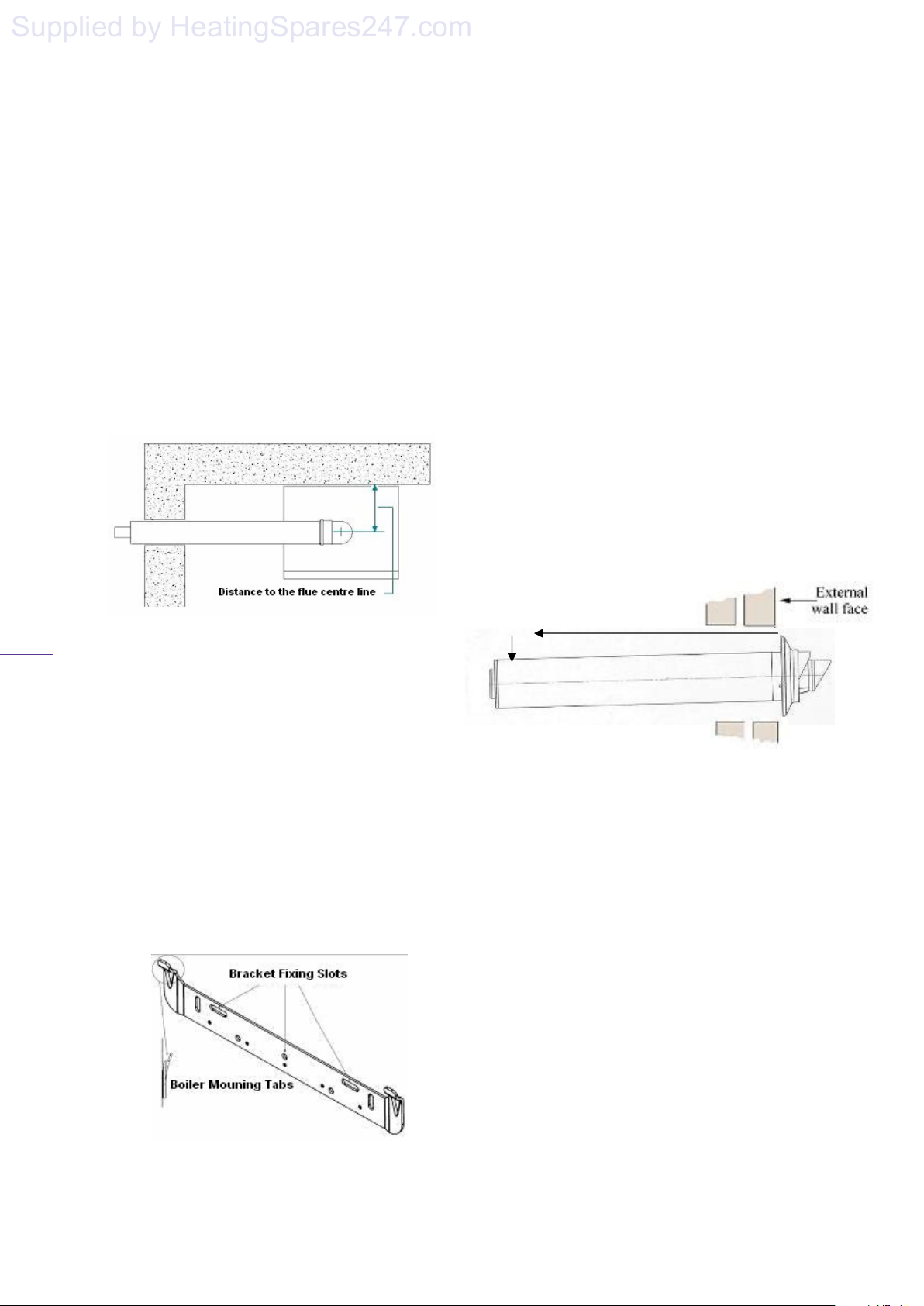
only). For flue side exit from the boiler - Mark
the horizontal flue centre line on the rear wall.
Extend the horizontal line to the side wall
allowing a 3% decline back towards the
boiler, to enable condensate to drain back
through the boiler. Mark the flue centre line.
( figure 11.)
Figure 11 (vertical Centre??)
10.7 Mount the boiler onto the fixing bracket via
the boiler mounting tabs, (figure 12).
10.8 Connect the isolation valves to the boiler
ensuring the filter valve is at the extreme right and
the sealing washers are fitted correctly.
10.9 On installing the flue, determine the
required length of the outer air duct by
measuring the distance 'L' (figure 13) from the
face of the external wall to the back of boiler's
elbow connecting collar. The measurement for
the inner flue duct will be 'L' + 20mm
10.10 Measuring from the back of the terminal
connection, mark distance 'L' onto the outer air
duct. (figure 13)
10.11 Cut the outer air duct only to the required
length ensuring that the cut is square and free from
burrs.
18
10.5 When cutting the flue hole it is
recommended that a 105mm diameter core
drill is used where both internal and external
access for the flue installation is available.
Where only internal access is available a
125mm diameter core drill should be used.
(Note: Please take adequate precautions to
prevent debris entering the boiler via the flue
outlet).
10.6 Using a 8·5mm drill bit, drill the holes for
fixing jig (optional) and hanging bracket.
Locate and secure the supplied wall mounting
bracket and fixing jig (if obtained) in position
(figure 12).
Figure 12
10.12 Measuring from the back of the terminal
connection, mark distance 'L' + 20mm (figure 14)
onto the inner flue duct and cut the duct to size,
ensuring that the cut is square and free from burrs.
10.13 Pass the flue assembly through the wall and
connect the assembly to the boiler, ensuring that
both the air and flue duct joints are fully pushed
home into the connecting elbow's collar.
10.14 With the flue tilted at 3
0
, allowing
condensate to drain back into the boiler, and joints
secured fit the flue trim to the external wall
surface using a suitable mastic. Note. Where
internal access only is available, the flue trim must
be attached to the flue assembly prior to passing
the assembly through the wall.
Page 18
Page 20
solaris 24PC, 30PC
L+20mm
Supplied by HeatingSpares247.com
19
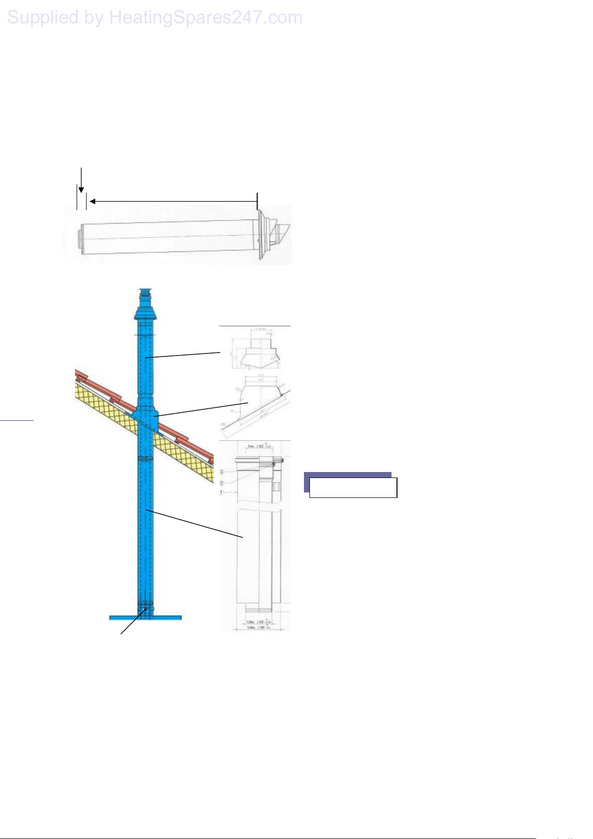
10.15 The vertical system diagram is shown in
figure 15a and 15b. Note: Maximum vertical
flue length is 8m with a 60/100mm flue
system.
L
Figure 15b
Figure 15a
10.16 Provisions to fill the boiler and system
must be made by the Installer, using an
approved filling loop. The filling loop used
must be approved to current water byelaws
and fitted as close to the boiler as practicable.
If it is not practicable to install the filling loop in
an obvious position please add a label on the
boiler to state where the filling loop can be found
for future reference. Please instruct the user how
to top up the system water pressure.
10.17 Connect the domestic hot water, cold water
inlet, heating system flow & return and pressure
relief valve pipework to the supplied boiler
fittings, ensuring that the pipework has been
correctly power flushed before final connection.
10.18 Condensing boilers of this type must have
the condensate drain connected to drainage
system. Due to the acidic nature of the condensate
the drainage system must be made of noncorrosive material such as plastic tubing..
Condensate should, if possible, be discharged into
the internal household draining system. If this is
not practical, discharge can be made externally
into the household drainage system or a purpose
designed soak away containing lime chippings.
Note if a soak away is used the drain must
terminate at least 500mm from the external wall.
10.19 The electrical connections to the boiler must
be in accordance with Section 9 of these
instructions.
11. Gas Supply
11.1 The gas supply pipe must be of 22mm copper
from the meter to the boiler and capable of
delivering the quantity of gas required by the
boiler (see Technical Data section 2) in addition to
the demand of any other gas appliances being
serviced from that supply.
11.2 The meter governor must be capable of
delivering a pressure of either 20mbar for natural
gas or 37mbar for propane gas, dependant on the
gas being used.
11.3 On final connection of the gas supply to the
boiler, the complete gas installation including the
gas meter, must be tested for tightness and purged.
Page 19
Page 21
contaminants
and dosed with sufficient anti
-
20
Supplied by HeatingSpares247.com
12. Filling the System
12.1 The boiler must not be operated without
water.
12.2 On completion of the boiler installation
and ensuring that all water connections are
correctly made the boiler may be filled with
water via the filling loop (not supplied with
the boiler). Ensure that two manual feed
valves and boiler isolation valves are open.
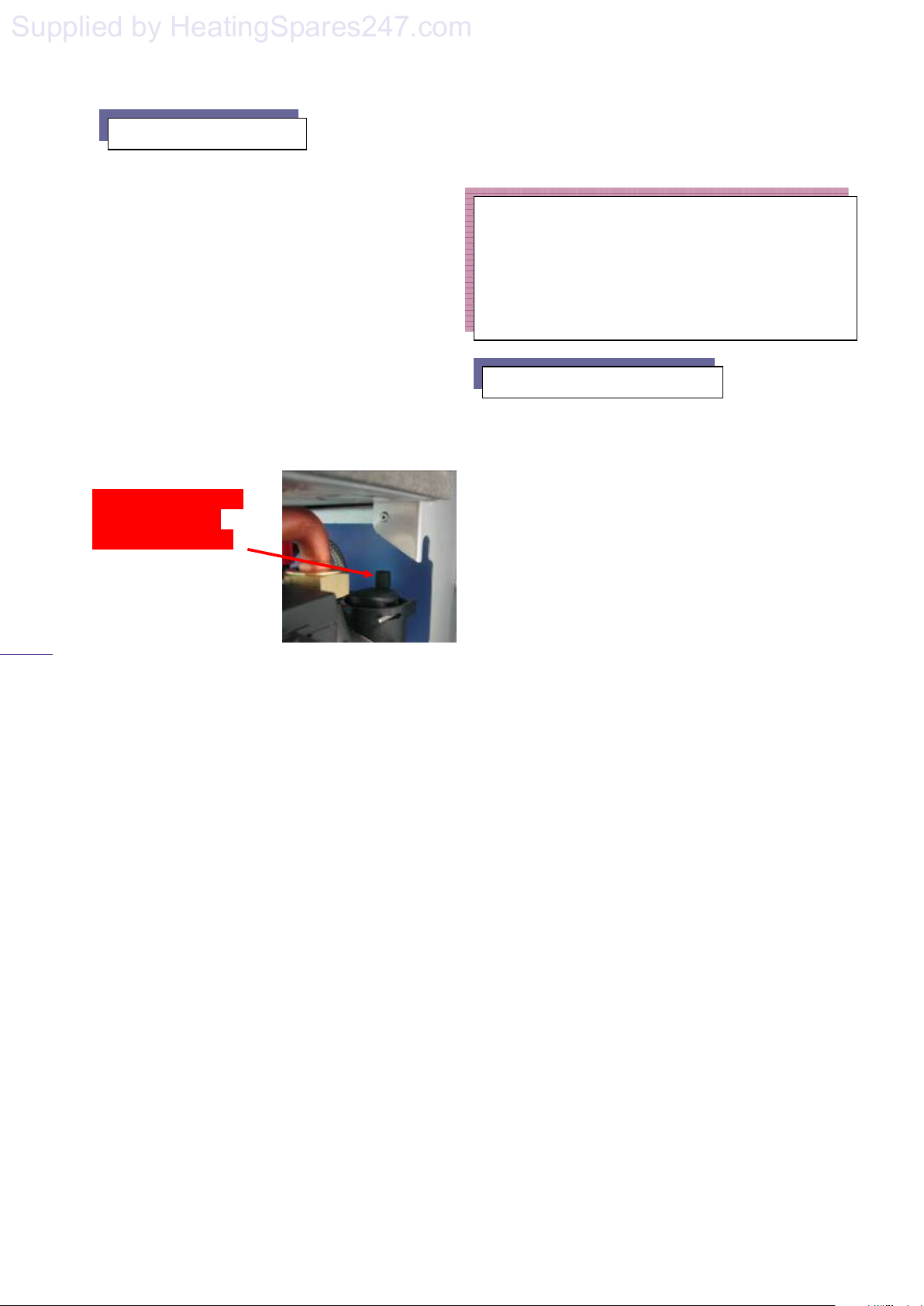
12.3 Release the cover cap on the boiler's
automatic air vent, located on top of the
internal pump (figure 16), when filling the
system.
Figure 16
Release the cover cap
(behind the pump)
When filling system
12.4 The manual feed valves must be closed
and the filling loop disconnected once the
pressure sensor, sited on the boiler’s control
panel, indicates a system pressure of 1.5bar.
12.5 Check that all the water connections
throughout the system are sound and bleed
each of the heating system’s radiators in turn.
12.6 Air must be vented from the boiler's pump
by unscrewing the pump’s integral vent plug
and allowing water to bleed for a few seconds.
Take care not to allow water to splash onto any
electrical components.
12.7 When the system is bled of any air the
system pressure must be topped until the
pressure LCD display indicates a system
pressure of 1.5bar.
12.8 If the pressure exceeds 1.5bar discharge
the excess pressure from the system via a
radiator valve or pipe connection. Do not use
the safety discharge valve as the valve seat
solaris 24PC, 30PC
may become contaminated with debris and fail to
re-seal.
Important Note.
In order to maintain operation and the appliance’s
warranty; after initial filling the heating system
must be thoroughly flushed using a propriety
cleanser to remove foreign material and
13. Control Panel Functions
13.1 Central heating and D.H.W. temperature
controls: The boiler's integral control unit
monitors and adjusts both the boiler’s hydraulic
circuit and D.H.W. water outlet temperatures by
means of sensors located on the C/heating and
D.H.W. flow outlets. The sensors convert the
water temperature into an electrical resistance that
is relayed back to the control potentiometers (2 &
3 figure 17) located on the control panel. The
respective potentiometer control dial allows
manual setting of the maximum required
temperature (reference value) between 30º and
85ºC for C/heating and 35º and 64ºC for D.H.W.
When the boiler functions in heating or D.H.W.
mode, the resistance measured is compared to the
manually set reference value. The differential
determines the modulation of the gas valve
adjusting the useful heat output generated and
stabilising the temperature to within +/-1ºC
13.2 Re-set function: Should the boiler lockout at any time, please check the gas supply
and ionisation probe position, the boiler may
be re-started by turning both the CH & DHW
to minimum, switching to the standby “O”
position and switching off at the fused spur or
socket (Switch 4 figure 7) waiting 30 seconds
and switching back to its previous position
once the fault has been eliminated.
13.3 Function switch: The three position
switch allows the boilers operation to be set to
Stand-by (centre position - O) ‘Heating +
D.H.W.’ (left) or ‘D.H.W. only’ (right).
Page 20
Page 22
solaris 24PC, 30PC
5
4
3 2 1
Supplied by HeatingSpares247.com
21
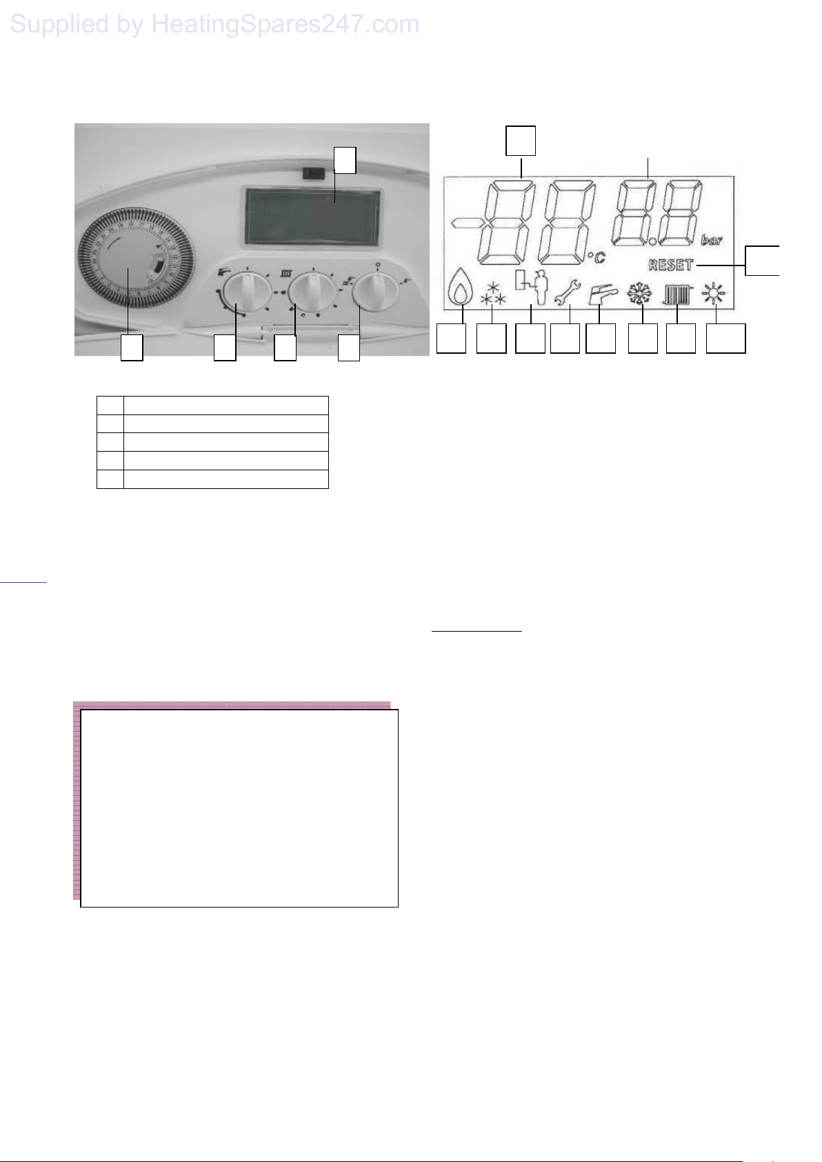
1- Mechanical Timer
2- D.H.W. temperature control
3- C/Heating temperature control
4- Function switch
5- LCD display
13.4 LCD display: While giving the
operational status of the boiler and water
temperature, to aid in fault diagnostics the
control unit has a built in facility that
automatically indicates the fault mode.
If
more than one fault simultaneously occurs,
then only the highest priority fault is
displayed.
Service mode function: Turn selector control
knob (3 figure 17) 3 times between C/H setting
and the off position (no more than 2 seconds
between each turn) the boiler is now in service
mode and will stay there for 15mins, turn both
C/H & DHW controls to max, this sets the
boiler to max output and will not modulate,
turn both the controls to min to set the boiler on
min without modulation for setting up the
default parameters.
1
2
Figure 18
3
4 5 6 7 8 9 10
1- C.Heating/D.H.W. water temperature and
failure code indicator
2- C.Heating water pressure value indicator
3- Flame indication
4- Frost protection indicator
5- Service computer connection indicator
6- Failure indicator
7- D.H.W. mode indicator
8- Winter mode indicator (Heating & Hot
Water)
9- C. Heating mode indicator
10- Summer mode indicator (Hot Water Only)
Reset indicator
Failure Codes:
F0 – The Water Pressure is Too LOW or
Too HIGH
F1 - Lockout due to overheating
F2 - D.H.W. temperature sensor damage
F3 - Primary temperature sensor damage
F4 - Ignition problem
F5 - Combustion product (flue) temperature
sensor damage
F6 - External temperature sensor damage
F7 - Problem with fan feedback signal
F8 - Fan speed out of set range
F9 - Fan is moving when it should be stationary
OC - External sensor is connected and OTC
enabled
CC - External sensor is disconnected and OTC
disabled and Flue sensor
11
Page 21
Page 23
solaris 24PC, 30PC
Supplied by HeatingSpares247.com
22
14. Commissioning
14.1 The boilers have been tested and pre-set
at the factory and is dispatched with its on
board controls set to provide a maximum
central heating and D.H.W. output of 24 kW
for Solaris 24, and 30kW for Solaris 30.
Consequently, once all the connections have
been made and the boiler has been filled with
water to the designed system operating
pressure, the boiler may be fired prior to
adjustment of its pre-set parameters to match
the heating systems requirements.
14.2 Prior to firing, check that the electrical
supply to the boiler is 'On' (Indication is
shown on the LCD display) and the gas
service cock is in the open position.
Set the boiler's central heating and
domestic hot water temperature controls to
maximum by turning them fully clockwise.
Set the external room thermostat (if fitted)
to maximum and set thermostatic radiator
valves to maximum.
14.3 Switch the boilers function switch to the
central heating and domestic hot water
position. The boiler's control unit will now
automatically carry out pre-ignition safety
checks before igniting the burner.
14.4 On burner ignition check the integrity of
the boiler's flue for tightness and correct
operation.
14.5 Check the boiler for correct domestic hot
water operation by opening and closing the
household domestic hot water draw off faucet.
14.6 In order to maintain the appliance
warranty after initial filling the heating system
must be thoroughly flushed using a propriety
cleanser to remove foreign material and
contaminants and dosed with sufficient anticorrosion inhibitor.
14.7 Restart the boiler and again allow the
central heating system to reach maximum
operating temperature. Check that all the water
connections throughout the system are sound and
bleed each of the heating systems radiators and
purpose made air release points in turn.
14.8 Check manual air vents, and bleed the heat
exchanger by means of the screw on the manual
air vent.
14.9 Check the system pressure and top up if
necessary to 1.5bar.
14.10 Reset the central heating & domestic hot
water temperature controls and room thermostat to
the desired temperature settings.
Important Notice.
• Failure to thoroughly power flush the boiler
and heating system or to add an anti corrosion
inhibitor to the system water will invalidate
the boiler's warranty.
• The condensate trap must be filled with water
and plastic discharge pipe connected to drain
before operating the boiler.
Page 22
Page 24
P7
P5
P2
P4
23
Supplied by HeatingSpares247.com
15. Onboard Adjustments
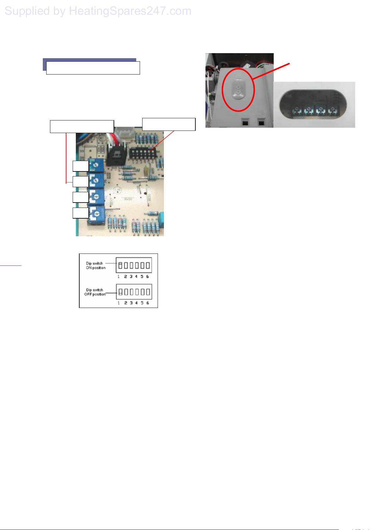
15.1 The boiler incorporates 4 potentiometers
and a bank of dip switches to allow adjustment
to its pre-set parameters. These are situated on
the rear of the control panel. (figure 19)
POTENTIOMETERS
DIP SWITCHES
Figure 19
The potentiometers can easily be accessed by
removing the cover on the rear of control
panel (Figure 20). However, to reach the dip
switches, the control panel must be opened.
P7 – Ignition fan ramp
(default setting 4 0’clock)
P5 – Anti cycle timer adjustment
(default setting 6 0’clock)
P2 - Boiler range adjuster
(default setting 4 0’clock)
P4 – Maximum Fan sped adjustment
(default setting 4 0’clock)
solaris 24PC, 30PC
Potentiometer
adjustment cover
15.2 Setting the maximum c/heating flow
temperature: The boiler is dispatched with a
maximum flow temperature factory set to 85°C.
Where a lower maximum temperature is required
such as in the case of under-floor heating,
the factory setting can be altered between a
maximum of 50°C and a minimum of 30ºC,
by setting dip switch '6' into ON position.
15.3 Setting the 45 second delay: The boiler is
factory set to exclude the delay of 45 seconds
before re-ignition between the closing of a hot
water faucet and CH start-up. This delay can be
set to 45 seconds by setting dip switch ‘3’
(figure 19) into the OFF position.
15.4 255 seconds delay setting: The boiler is
capable of up to 255 seconds ignition delay (anti
cycling time) before re-ignition following burner
shut down on the primary hydraulic water
reaching its set temperature. This delay can be
increased up to a maximum of 255 seconds by
turning potentiometer P5 (Figure 19) clockwise.
15.5 Pump working mode setting: The boiler has
a factory set to operate the pump for pre-purge and
post-purge times (45 sec.). This delay can be
excluded by fitting dipswitch ‘2’ (figure 19) into
ON position. However, this may then cause the
boiler over-heat thermostat to trip out.
15.6 The maximum and minimum heat output for
heating is adjusted via potentiometer P2 (figure
19) which changes the fan speed and thus the gas
rate. It is not necessary to make further
adjustments.
Page 23
Page 25
solaris 24PC, 30PC
Supplied by HeatingSpares247.com
24
15.7 Ignition fan ramp. The graduated
opening of the gas valve for ignition rate is
governed by the 1
st
potentiometer P7 control,
which is factory set to 4 o’clock. Adjustment
from minimum to maximum rate is made by
turning the potentiometer fully clockwise.
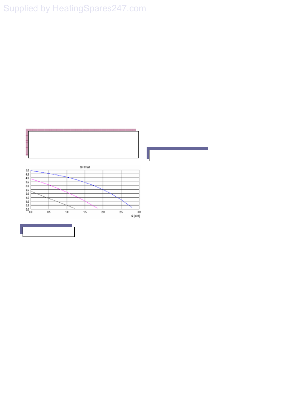
15.8 The boilers integral pump is factory set
to its maximum speed setting to give a 1000
l/hr flow on a nominal 4m head. The pump
may be adjusted to a lower speed to match the
designed c/heating system requirements.
(figure 22)
Important .
Dip Switch 4 and Dip Switch 5 (figure 19) are
factory set and must not be adjusted.
16. Safety Devices
16.1 An hydraulically operated primary
pressure sensor monitors water pressure in the
primary hydraulic circuit and will flash should
the pressure drop below 0.8bar, and switch off
the boiler if the pressure drops below 0.3bar or
rises above 3bar. The boiler will not operate
until the correct system pressure has been
correctly re-stored and the boiler reset, see
13.2.
16.2
The temperature of the water flowing
from the primary heat exchanger is monitored
by an overheat thermostat located on the outlet
pipe. If the water temperature gets too hot the
switch opens, cutting off the electrical supply
to the gas valve and causing the boiler to
‘Lock-out’. Once activated the boiler has to
be manually re-set. Refer to section 13.2.
16.3 The boiler's control unit has an in-built frost
protection device that fires the boiler's burner
when the temperature of the primary hydraulic
water falls below 6°C. The device works
irrespective of any room thermostat setting and
will protect the complete heating system. Once the
water temperature reaches 16°C the boiler reverts
back to normal operation.
16.4 If there is a fault on the DHW sensor, the
boiler continues to operate by controlling DHW
outlet temperature by using the CH temperature
sensor, which limits the water temperature at 65ºC
during DHW operation. If such a failure occurs a
fault code will be displayed on the LCD display,
please contact your service agent.
17. Routine Servicing
17.1 To ensure the continued efficient and safe
operation of the boiler it is recommended that it is
checked and serviced regularly. The servicing
must be carried out by a competent person in
accordance with the Gas (Safety and Use)
Regulations. The frequency of servicing will
depend upon the particular installation conditions
and usage, but in all cases the boiler must be
serviced at least once a year.
17.2 Following servicing of the boiler the relevant
sections of the 'Benchmark' Installation,
Commissioning and Servicing Log Book must be
completed.
17.3 Prior to servicing check the flue operation,
terminal guard (if fitted) and the boilers operation.
17.4 Ensure that both the electrical and gas
supplies to the boiler are isolated before
commencing service of the boiler.
17.5 Remove the boiler casing as follows:
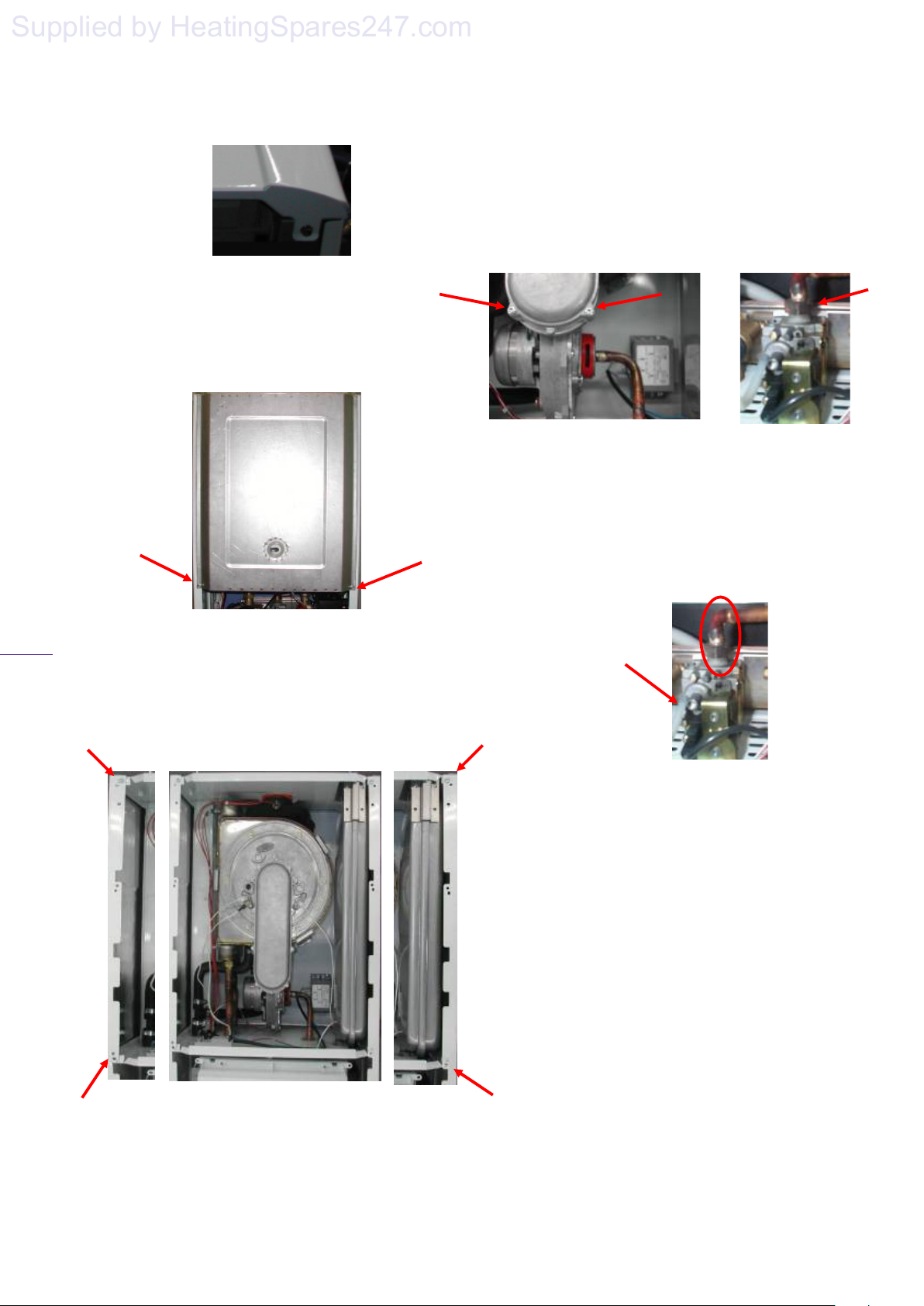
Open the front panel by removing two screws
at the bottom of the boiler (figure 23).
Page 24
Page 26
solaris 24PC, 30PC
Supplied by HeatingSpares247.com
25
Figure 23
17.6 Release the hermetic chamber cover by
removing the two screws (figure 24) and then
lifting the cover to release it from the retaining
hooks at the top of the boiler.
Figure 24
Release the side panels by removing the
screws on the upper and lower sides
(figure 25). Remove the panels by
swinging them out and lifting them up.
17.7 Disconnect the electrical leads and gas valve
pipe connection from the fan (disconnect at the
gas valve taking care not to damage the restrictor),
remove the fan securing screws.
Figure 26 Figure 27
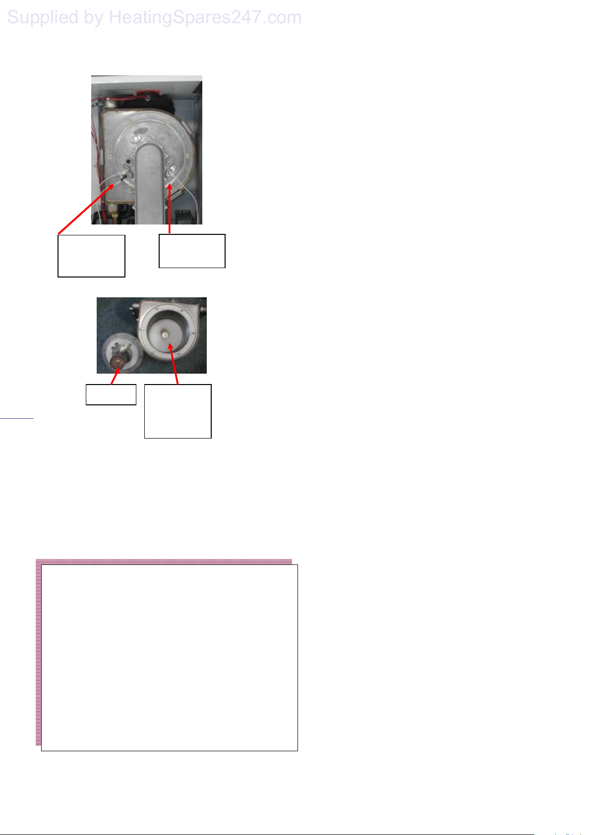
17.8 Remove the burner assembly from the
combustion chamber as follows:
Disconnect and remove the gas supply pipe
between the gas valve and fan, taking care not
to damage the restrictor in the top of the gas
valve.
Figure 28
Pull off the ignition and flame electrode leads
from the PCB and ignition transformer, and
remove the wires through the grommet on the
lower combustion chamber.
Remove the burner-retaining nuts and extract
the burner (figure 30).
Page 25
Page 27
26
Supplied by HeatingSpares247.com
Figure 29
,
Ignition
electrodes
Ionisation
electrode
Figure 30
Burner Premix
heat
exchanger
17.9 Visually check for debris/damage and
clean or replace as necessary the following
items:
⇒ Heat exchanger
⇒ Burner
⇒ Fan/compartment
⇒ Electrodes
⇒ Insulation/gaskets
IMPORTANT
Clean the heat exchanger using a soft brush or
vacuum cleaner. Do not use any tool likely to
damage the finish of the heat the exchanger.
Clean the burner by washing in soapy water.
Allow to dry thoroughly before re-fitting
Do not use wire or sharp instrument to clean the
burner ports.
Ensure the ignition electrode gap is set to
4 mm.
Ensure the electrodes are 7mm from
the burner surface.
Ensure the Ionisation probe is 8mm from
.
the burner surface.
17.10 Cleaning the Condensate trap. Extract the
bottom part of condensate trap, by turning anticlockwise. If this is difficult to remove then
dependant on which trap is used either use an
appropriate spanner or pull off the hose from the
bottom of the trap and use an appropriate allen key
in the socket provided. Clean the trap using a
household proprietary cleanser, preferably
containing bleach.
17.11 The boiler is fitted with a cold water inlet
filter, which must be inspected during each
service. To gain access to the filter:
Close the isolating valve on boiler's cold water
inlet by turning the valve head full clockwise.
Open one or more hot water taps to drain
boiler circuit.
Disconnect the cold water inlet connection to
the boiler.
Clean and inspect the filter, replace if
necessary as described in (18.18).
Re-fit the filter and reinstate the cold water
inlet connection to the boiler.
Fully open the isolating valve on the boiler's
cold water inlet and check for leaks
.
17.12 On completing the service reassemble the
boiler components in reverse order ensuring that
all component joints and gaskets are sound. Any
damaged gaskets must be replaced.
17.13 Reinstate the boiler's electrical and gas
supplies and check for gas tightness and correct
boiler operation.
Page 26
solaris 24PC, 30PC
Page 28
solaris 24PC, 30PC
Supplied by HeatingSpares247.com
27
18. Component Replacement
CAUTION!
While there are no substances harmful to health
contained within this appliance, some component
parts of the boiler (insulation pads, gaskets and rope
seals) are manufactured from man made fibres.
When damaged or broken these fibres may cause a
temporary irritation. High dust levels may irritate
eyes and upper respiratory system. It is important
therefore, that sensible precautions are applied
when exchanging components.
18.1 Ensure that both the electrical and gas
supplies to the boiler are isolated before
replacing any component part.
18.2 To prevent the need to drain the entire
heating system when replacing the boiler's
integral pump, expansion vessel, safety relief
valve and pressure sensor, the boiler’s
hydraulic circuit may be isolated from the
central heating circuit by closing the boilers
isolation valves. Opening the drain valve at the
back of the pump will then drain the boiler’s
hydraulic circuit.
18.3 For replacement of the following
components it will be necessary to remove the
boiler casing panels as described in Section
17.
18.4 Domestic hot water sensor
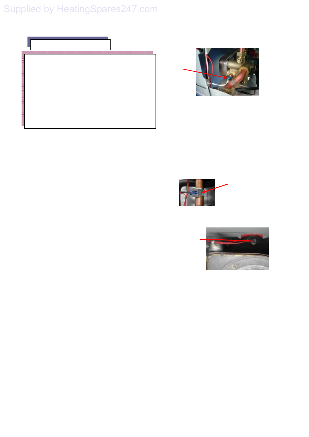
The domestic hot water probe is located on
the left side of the diverter valve, hot
water side. (figure 31)
Carefully disconnect the leads from the
sensor.
Remove the sensor using a 13mm spanner.
Fit the replacement sensor sealing as
required.
Re-fit the leads to the replacement sensor
Figure 31
18.5 Central heating and Flue sensor
The Central heating ntc sensor is located on the
flow pipe.
The Flue sensor is located on the plastic flue
socket.
Disconnect the leads from the sensors.
Remove the sensors from the pipe/plastic flue.
Fit replacement sensors.
Fit the leads to replacement sensors.
Central heating
NTC sensor
Figure 32
Flue NTC
sensor
18.6 Fan Unit
Remove the burner/fan assembly as in 17.8.
Remove the electrical leads from the fan.
Disconnect the fan.
Fit the replacement fan unit in reverse order
and reconnect all electrical leads before
reassembling to the combustion chamber.
Page 27
Page 29
solaris 24PC, 30PC
Supplied by HeatingSpares247.com
28
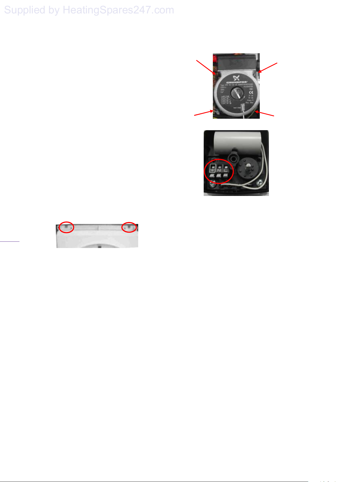
18.7 Printed circuit board (PCB)
Turn off and isolate electrical supply.
Remove interface cover by lifting the two
latches. (figure 33)
Remove the electrical connections to the
PCB, taking note of where the connections
are fitted, by releasing the clips and
carefully pulling off the connectors.
Release the 5 screws securing the PCB to
the control panel and lift out the PCB.
Fit the replacement PCB in reverse order
of removal, ensuring that the PCB
electrical connections are fully pushed
home.
Check that the on board adjustments to the
same value as the old PCB. Re-set as
necessary, ref section 15.1.
Figure 33
18.8 Pump
The order of removal is different
dependant on the failure of the motor or
plastic body.
In case of motor failure:
Drain the boiler’s hydraulic circuit as
detailed in 18.2.
Disconnect the screws connecting the
pump motor to the body, figure 34.
Pull out the motor and disconnect the
electrical connections from the pump cable
housing.
Figure 34
Figure 35
Fit the replacement motor in reverse order
ensuring the correct polarity of the electrical
connections.
Open the isolating valves on the flow and
return connections, refill, vent and repressurise the water system ensuring the pump
union joints are sound.
In case of body damage:
Remove the motor as described above.
Remove the secondary heat exchanger as
detailed in 18.9.
Remove the expansion vessel pipe by
releasing the clip on the pump body.
Remove the pressure sensor connection as
detailed in 18.16.
Disconnect the pumps outlet fitting.
Page 28
Page 30
29
Supplied by HeatingSpares247.com
Figure 36
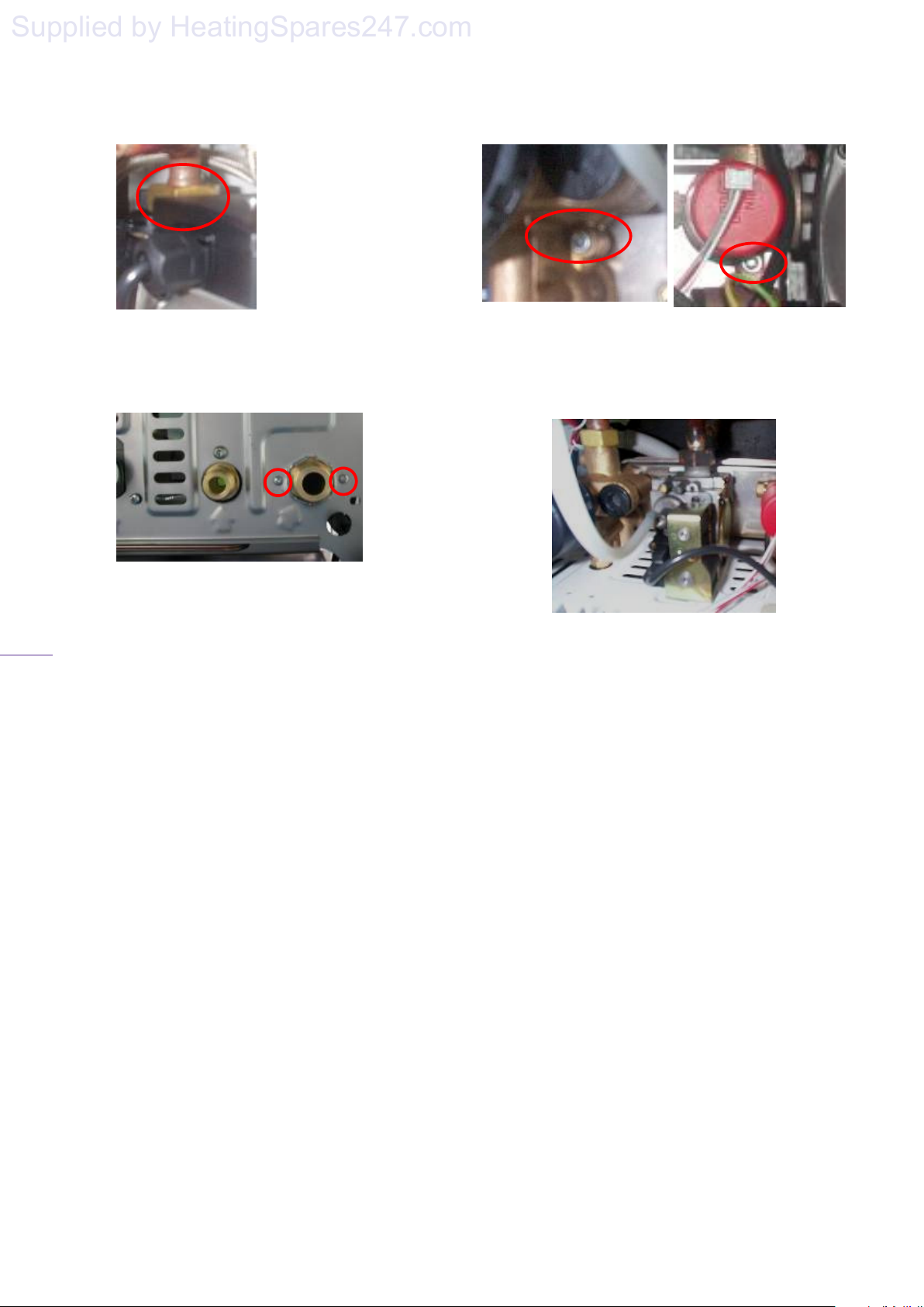
Remove the fixing screws on the pump and
hydraulic block, located at the bottom right
of the boiler. (figure 37)
Figure 37
Remove the pump body assembly.
Detach the pump body from the hydraulic
block by removing the clip.
Fit the replacement body in reverse order
ensuring that the pump washers are fitted
and correct polarity of the electrical
connections.
Open the isolating valves on the flow and
return connections, refill, vent and repressurise the system ensuring the pump
union joints are sound.
18.9 Secondary Heat Exchanger
Drain the boiler’s hydraulic circuit as
detailed in 18.2.
Remove the two screws, which connect the
heat exchanger to the hydraulic block.
(figure 38)
solaris 24PC, 30PC
Figure 38
Remove the heat-exchanger after removing the
diverter valve as described in section .
Figure 39
Fit the new heat exchanger and reassemble the
boiler in reverse order ensuring all washers are
fitted. (Replace and damaged washers or seals)
Open the isolating valves on the flow and
return connections, refill, vent and repressurise the system ensuring all joints are
sound.
18.10 Primary Heat Exchanger and Burner
Drain the boiler’s hydraulic circuit as detailed
in 18.2.
Disconnect the pipes from the heat exchanger.
Release the union connections on the pump
and hydraulic block, retaining the washers for
re-assembly, replace if damaged.
Remove the pump, heat-exchanger and heat-
exchanger three-way valve connecting pipes.
Remove the burner as detailed in 17.8.
Page 29
Page 31
solaris 24PC, 30PC
Supplied by HeatingSpares247.com
30
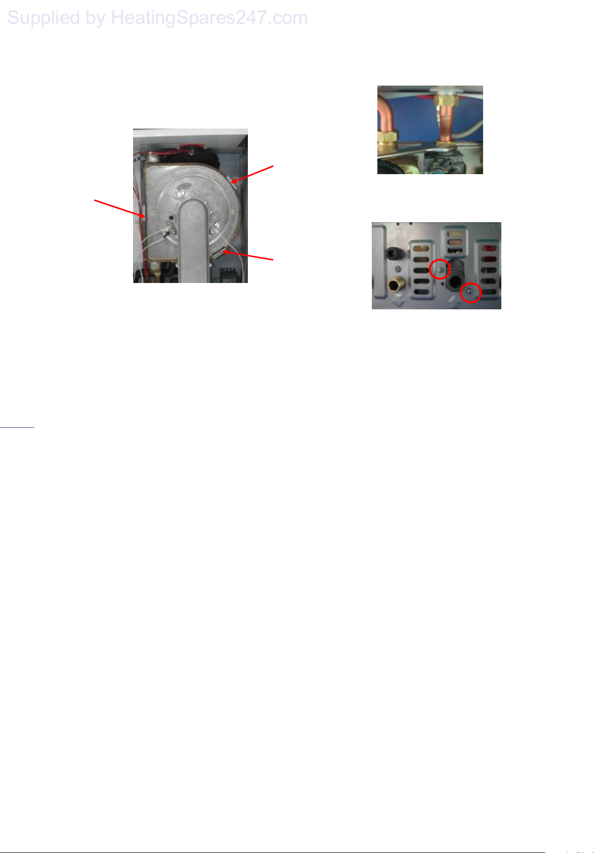
Remove the fixing brackets on the heat-
exchanger shown in figure 40
Figure 40
Remove the heat exchanger and burner by
pulling forward.
Fit the new heat exchanger and reassemble
the boiler in reverse order ensuring all
washers are fitted. (Replace any damaged
washers or seals as required)
Open the isolating valves on the flow and
return connections, refill, vent and repressurise system ensuring that all joints
are sound.
Check the manual air-vent, and vent the air
from the heat exchanger by means of
screw on manual air-vent.
18.11 Gas valve
Ensure that gas supply to boiler is turned
off.
Disconnect the electrical connections to
the gas valve, and silicone tube.
Release the main gas supply tube
connection from the top of the gas valve
and manifold inlet.
Figure 41
Remove the gas valve's two securing screws
and washers from the bottom side of boiler.
Figure 42
Rotate the gas pipe and withdraw the gas valve
assembly, taking care not to loose the
restrictor in the top of the valve.
Remove the restrictor and fit into the new
valve.
Refit in reverse order of removal, replacing
both washers as required.
Check for gas tightness and correct boiler
operation.
Where necessary the gas valve settings may be
re-calibrated by the following method:
18.12 Zero adjustment setting
Insert a combustion analyser into the socket on
the flue adapter.
Remove the brass screw to access the
adjustment socket. (Figure 43)
Turn the boiler's function switch to the
‘heating/hot water’ position. (4 figure 17)
Turn the central heating temperature control to
maximum setting. (2 figure 17)
Turn Potentiometers P2 & P4 (figure 19)
anticlockwise to the minimum setting.
Page 30
Page 32
solaris 24PC, 30PC
Supplied by HeatingSpares247.com
31
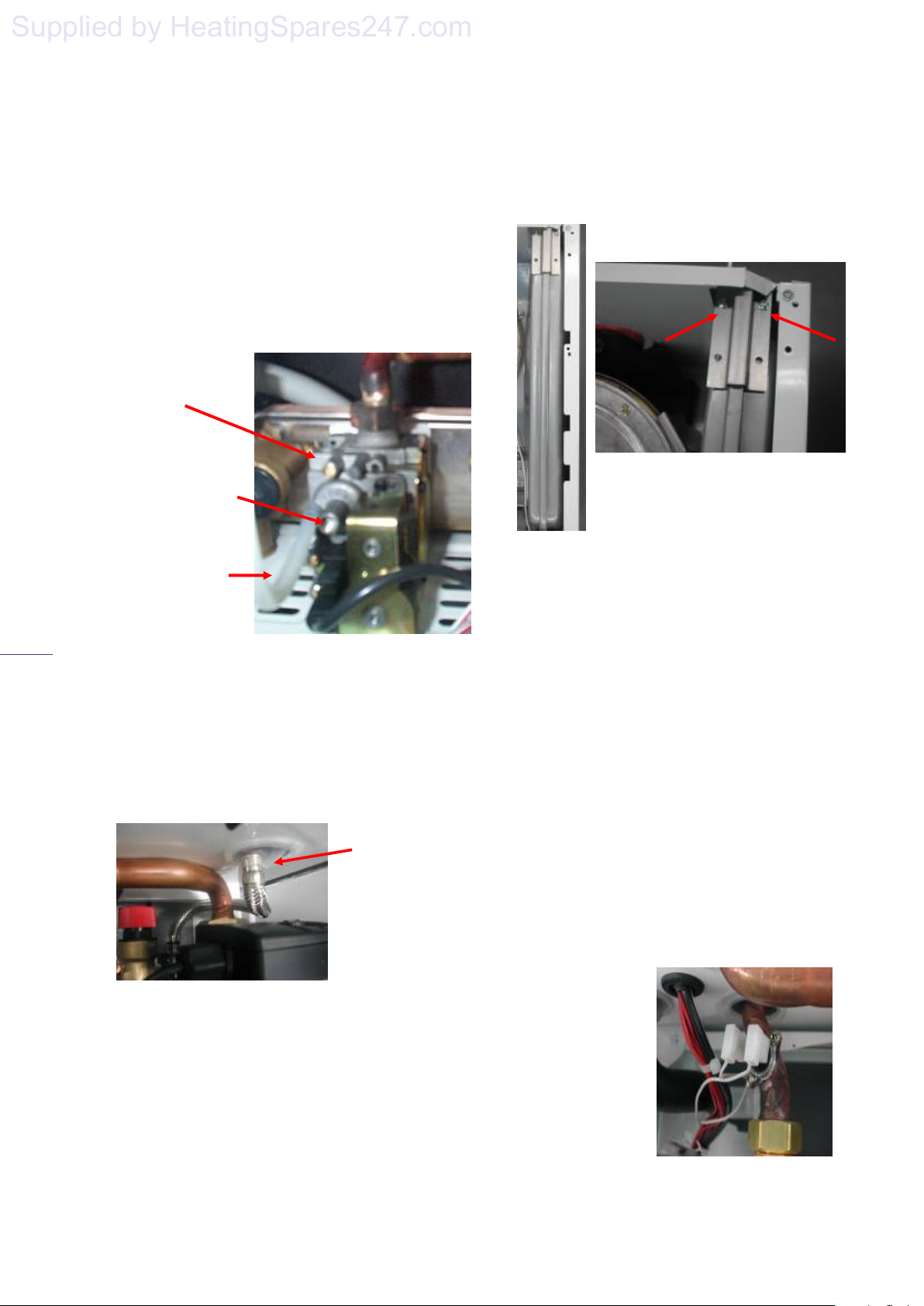
Using a 4mm allen key adjust clockwise:
to increase the CO
to decrease the CO
setting, anticlockwise:
2
setting by means of a
2
4mm allen key. (Natural Gas 9%, LPG
10%)
After adjustment, insert the brass screw and
re-set the potentiometers as follows P7, P2 &
P4 to 4
Figure 43
Feedback
silicone pipe
Zero adjustment
socket (4mm allen
key)
Inlet gas pressure
testpoint
18.13 Expansion vessel
Drain the boiler’s hydraulic circuit as
detailed in 18.2.
Disconnect the pipe coupling on the
expansion vessel (figure 44).
Figure 44
Remove the side panels (figure 25).
Remove the securing bracket. (figure 45)
Lift the pressure vessel out of boiler from
the gap over the chasis and fit the
replacement vessel to the boiler in reverse
order of removal ensuring the sealing washer
is fitted to the pipe connection before
tightening. (Replace the washer if required)
Figure 45
Using a pressure sensor, check that the
expansion vessel charge pressure is 0·5bar
(7·5psi) re-charge if necessary.
Open the isolating valves on the flow and
return connections, refill, vent and pressurise
the boiler ensuring all joints are sound.
18.14 Overheat safety thermostat
Remove the front panel. (figure 23)
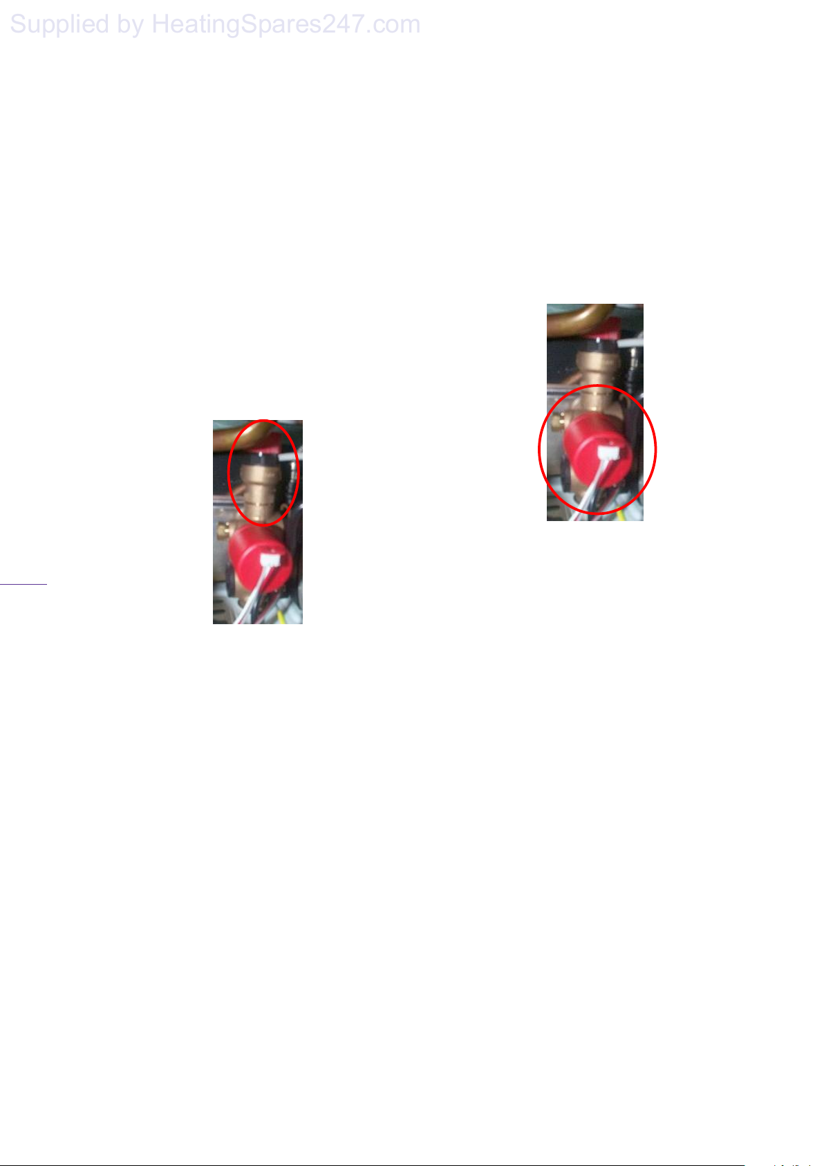
Locate the overheat safety thermostat
upstream of the three way valve (figure 46)..
Disconnect the electrical connections from the
thermostat.
Remove the thermostat from the pipe being
careful not to damage the retaining clip.
Fit the replacement thermostat in reverse order
to removal.
Figure 46
Page 31
Page 33
solaris 24PC, 30PC
Supplied by HeatingSpares247.com
32
18.15 Pressure relief valve.
Drain the boiler’s hydraulic circuit as
detailed in 18.2.
Disconnect the discharge pipe on the outlet
of safety valve.
Disconnect the safety valve from the
hydraulic block retaining the o-ring for use
on reassembly.
Fit the replacement safety valve in reverse
order to removal and refill, vent and
pressurise the boiler ensuring all joints are
sound.
Figure 47
18.16 Pressure sensor
Drain the boiler’s hydraulic circuit as
detailed in 18.2.
Disconnect and remove the sensor cable
and sensor from the flow sensor housing.
(figure 48)
Fit the replacement pressure sensor in
reverse order ensuring the gasket is
correctly fitted. (Replace the gasket if
damaged)
18.17 Flow sensor housing
Drain the boiler’s hydraulic circuit as
detailed in 18.2.
Remove the secondary heat exchanger as
detailed in 18.9.
Release the pump outlet pipe nut and rotate the
pipe for ease of removal.
Remove the pump, motor and body together
with the flow sensor housing as detailed in
18.8.
Remove the section of the housing from the
pump by releasing the clip.
Figure 48
18.17 Flow sensor housing
Drain the boiler’s hydraulic circuit as detailed
in 18.2.
Remove the secondary heat exchanger as
detailed in 18.9.
Release the pump outlet pipe nut and rotate the
pipe for ease of removal.
Remove the pump, motor and body together
with the flow sensor housing as detailed in
18.8.
Remove the section of the housing from the
pump by releasing the clip.
Disconnect the diverter valve motor electrical
connection and remove the motor by releasing
the clip as described in 18.20.
Release the nut connecting CH outlet
connection to the diverter valve (figure 49).
Page 32
Page 34
solaris 24PC, 30PC
Supplied by HeatingSpares247.com
33
Figure 49
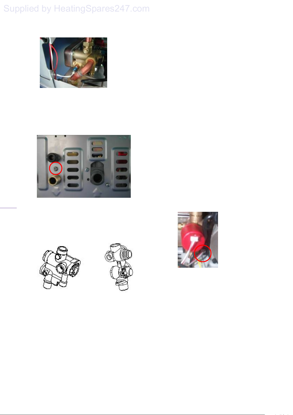
Disconnect DHW sensor as described in
18.4.
Remove the screw securing the remaining
section of the diverter valve to the
combination boiler (figure 50).
Figure 50
Fit the replacement diverter valve and flow
sensor housing (figure 51) in reverse order
of removal ensuring all components are
assembled correctly.
Figure 51
Open the isolating valves on the flow and
return connections, refill, vent and
pressurise boiler ensuring all joints are
sound.
18.18 Filter
Drain the boiler’s hydraulic circuit as detailed
in 18.2.
Remove the flow sensor housing as described
in 18.8.
Remove the filter on the inlet of the housing.
Clean or fit replacement filter.
Assemble the components in reverse order of
removal ensuring all components are
assembled correctly.
Open the isolating valves on the flow and
return connections, refill, vent and pressurise
the boiler ensuring all joints are sound.
18.19 Flow sensor
Remove the flow sensor by using a pair of
snipe nose pliers (figure 52).
Figure 52
Fit the replacement sensor in reverse order to
removal, using the cable connector if required.
Page 33
Page 35
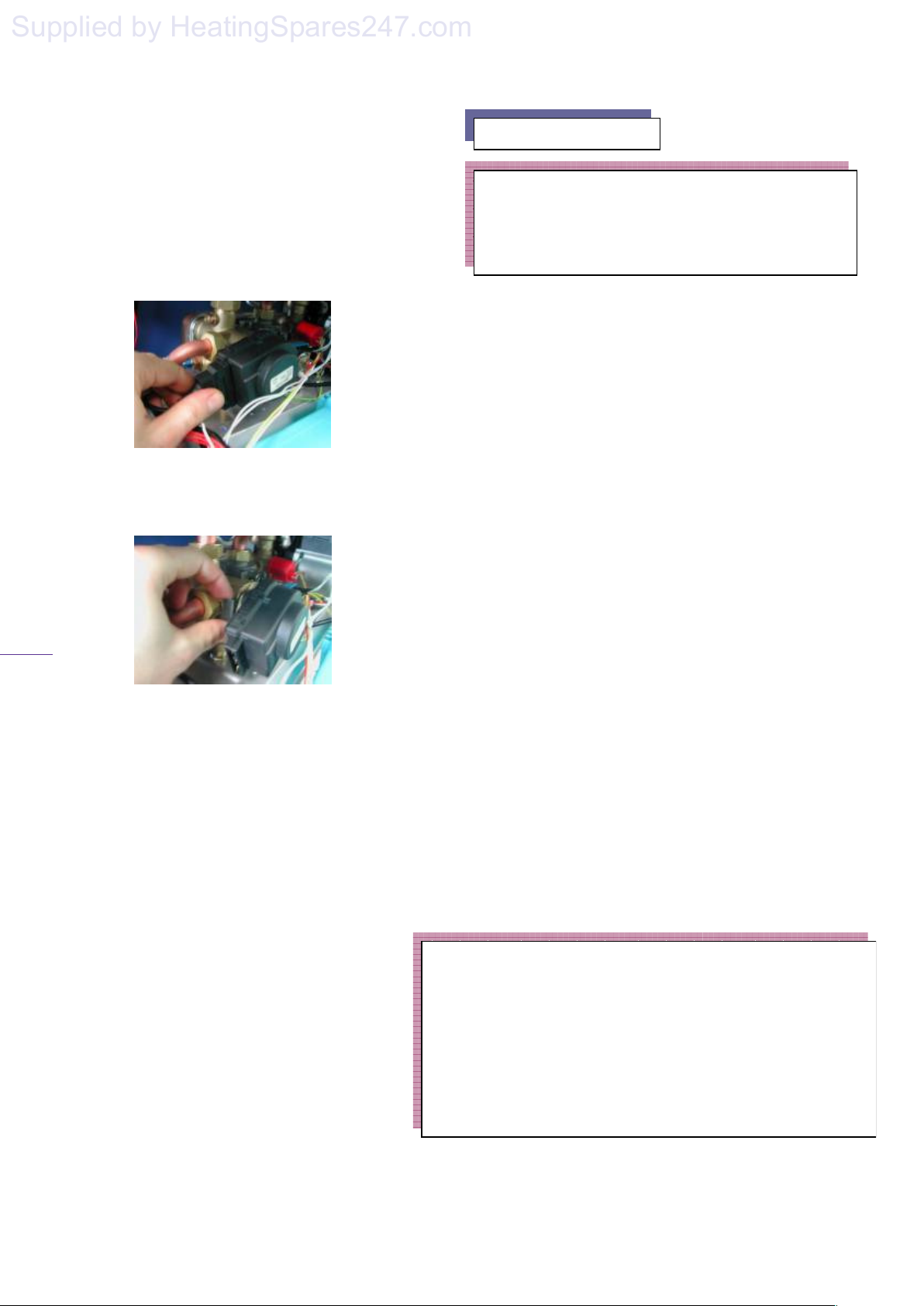
34
Supplied by HeatingSpares247.com
18.20 Diverter valve
Figure 44
Ensure that the electric supply to the boiler
is isolated from the mains supply.
Disconnect the electrical connection from
the diverter valve motor (figure 53).
Figure 53
Remove the clip connecting the motor to
the diverter valve (figure 54).
Figure 54
Fit the replacement valve in reverse order
ensuring the valve is fitted correctly.
Important.
Gas type conversion must be completed by attaching the
labels included in the gas conversion kit to the boiler.
• Type of gas label – place in a visible position inside the
• Grey label – cover the existing gas type on the data plate.
• Instruction label – Position inside the drop down cover on
19. Gas Conversion
Warning
Gas conversion must be carried out by a competent
person as defined in the Gas Safety (Installation
and Use) Regulations.
19.1. If gas conversion is required (from NG to
LPG etc.), follow the instructions below using
only approved components from your agent:
A flue gas analyser must be used when making
any adjustments that can affect the combustion
characteristics of the boiler. (this includes
converting to a different gas type )
Fit the new air/gas mixer ring after
disconnecting the gas pipe from the gas valve
(see figure 26.
Adjust dip switch 1 (figure 19) to the “On”
position for LPG, “Off” for NG, on the main
circuit board.
Change the diaphragm, which is located in the
outlet of the gas valve. {LPG 24kW - 4.7mm
(Brown), LPG 30kW - 5.35mm (Grey), NG
24kW – 6.5mm (Black), NG 30kW – 7.0mm
(White)}
Once re-assembled check for gas tightness.
Set the CO
as described in section “Zero
2
adjustment” following the instructions in
section 18.12 noting the correct CO
the type of gas that will be used.
Check the boiler for correct operation.
boiler.
the front of the boiler.
solaris 24PC, 30PC
value for
2
Page 34
Page 36

solaris 24PC, 30PC
Supplied by HeatingSpares247.com
35
NOTE:
When installing, commissioning or servicing
a gas appliance that incorporates a pre-mix
burner and zero-set governor, because it is not
possible to measure an operating pressure the
engineer should first check that the gas supply
is metered and ascertain whether it is possible
to measure the gas rate. If the gas input rate
can be measured then the requirements of
GSIUR 26(9) can be met, including any
specific requirements in manufacturers’
instructions.If gas input rate cannot be
measured then, to satisfy the intent of GSIUR
26(9), the engineer shall measure the
combustion quality of the appliance in
accordance with BS 7967 or the technical
data of this manual.
If the engineer does not have the required
equipment and no alternative test is specified
by the manufacturer then the appliance shall
be turned off and disconnected as an uncommissioned appliance until such time that
equipment is available to undertake such
tests.
Page 35
Page 37
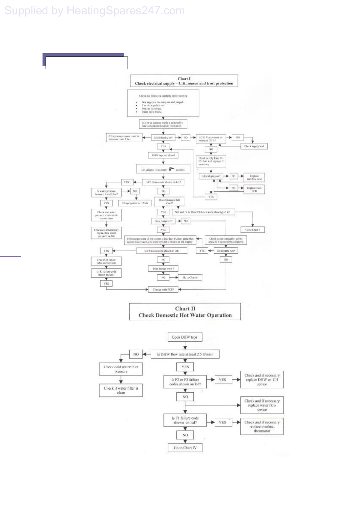
solaris 24PC, 30PC
Supplied by HeatingSpares247.com
36
20. Fault Finding Chart
Page 36
Page 38
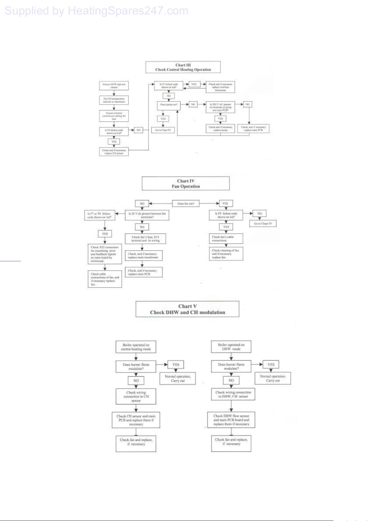
solaris 24PC, 30PC
Supplied by HeatingSpares247.com
37
Page 37
Page 39
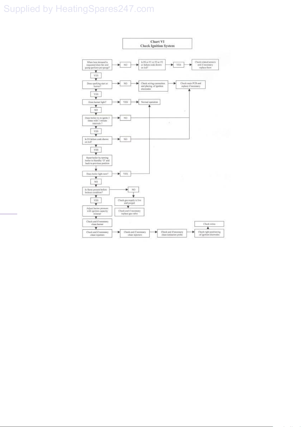
solaris 24PC, 30PC
Supplied by HeatingSpares247.com
38
Page 38
Page 40
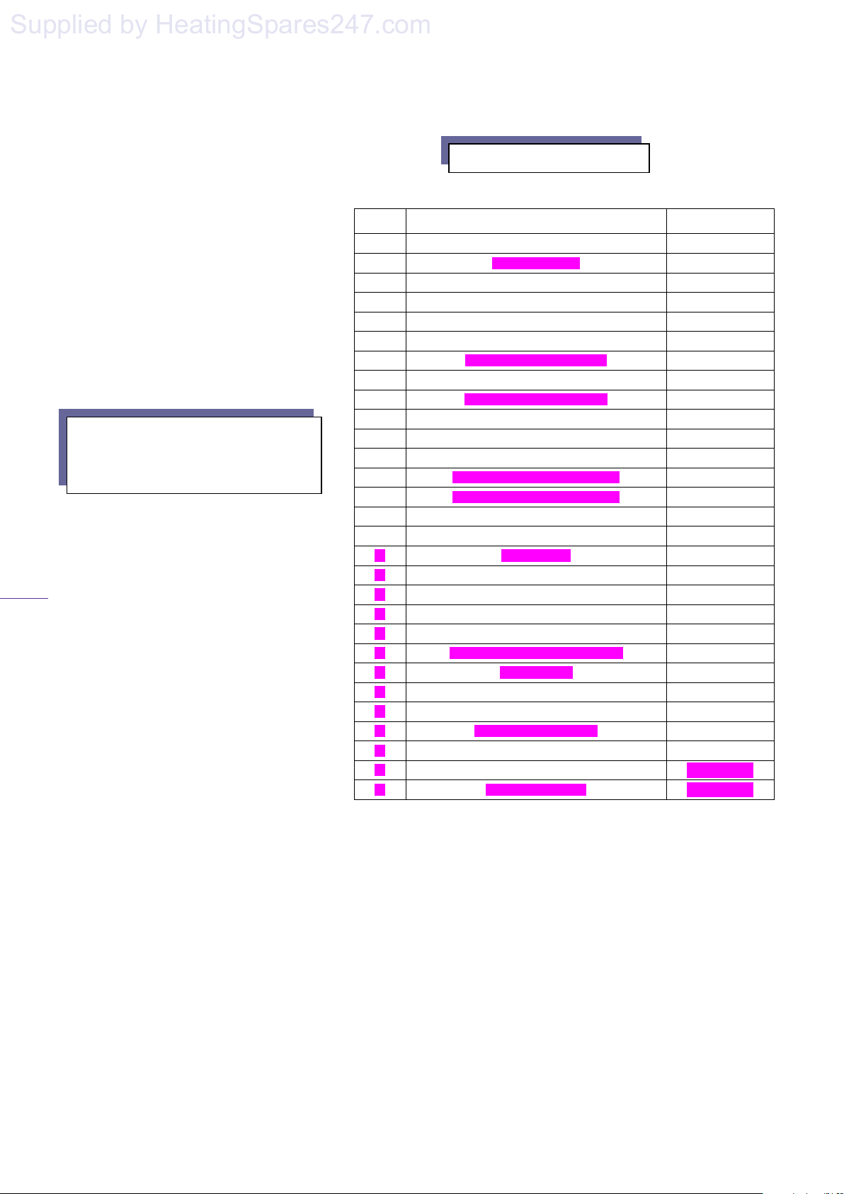
solaris 24PC, 30PC
Supplied by HeatingSpares247.com
39
APPENDICES
PART
No.
1 PRESSURE RELIEF VALVE
2 PUMP ASSEMBLY
3 EXPANSION VESSEL
4 GAS VALVE
5 AIR/GAS MIXER
6 AIR/GAS MIXER RING (RED)
7 PLASTIC DROP DOWN DOOR
8 PCB BOX
9 PCB MAIN CONTROL BOARD
10 INTERFACE BOARD
11 WIRING HARNESS WITH TIMER
12 MAIN FLY LEAD
13 PLATE HEAT EXCHANGER (30kW)
14 PLATE HEAT EXCHANGER (24kW)
15 DHW SENSOR (NTC)
16 CH SENSOR (NTC)
17 FLUE SENSOR
18 FAN
19 LIMIT THERMOSTAT
20 MAIN TRANSFORMER
21 SPARK GENERATOR
22 IGNITION ELECTRODE WITH LEAD
23 EARTH CABLE
24 IONISATION ELECTRODE
25 DIVERTER VALVE MOTOR (ONLY)
26 FLOW SENSOR HOUSING
27 DIVERTER VALVE
28 FRONT PANEL
29 CONDENSATE TRAP
Appendix 1 Spare Parts List
DESCRIPTION ORDER CODE
3003200019
3003200022
3002209497
3003200657
3003200658
3003200659
3003200084
3003200601
3003200662
3003200905
3003200915
3003200780
3003200897
3003200031
3003200152
3003200660
3003200397
3003200661
3003200663
3003200902
3003200903
3003200904
3003200039
3003200018
3003200017
3003200928
3003200461
Page 39
Page 41
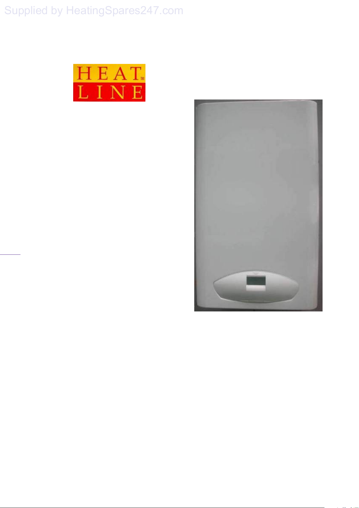
solaris 24PC, 30PC
Supplied by HeatingSpares247.com
40
24/30PC Pre-mix
Combination Boiler
User Instructions
SOLARIS
Condensing
Wall Mounted
Page 40
Page 42
solaris 24PC, 30PC
Supplied by HeatingSpares247.com
41
Natural Gas
Heatline Solaris 24PC/30PC Pre-mix Condensing
Combination Boiler
British Gas Service Listing
Solaris 24PC G.C.No 47-157-04
Solaris 30PC G.C.No 47-157-05
The Heat Line™ range of heating boiler are manufactured
from high quality materials, enabling reliability and
optimum performance.
Heat Line™ are committed to the continual development of
their appliances to ensure their customers benefit from the
latest advances in combustion technology and energy
savings.
Notified Body IMQ 51BP2750
CE Directive 90/396/EEC
CE Directive 92/42/EEC
The manufacturer, in the continuous process to improve
his products, reserves the right to modify the data
expressed in the present documentation at any time and
without prior notice.
The present documentation is an informative support
and it cannot be considered as a contract towards third
parties.
'Benchmark' Log Book, Boiler Registration &
SEDBUK
As part of the industry-wide initiative the boiler comes
complete with an Installation, Commissioning and Service
Record Log Book. Please read the Log book carefully and
in accordance with current legislation, complete all
sections relevant to the appliance and installation. The
details within the Log Book will be required in the event
of any warranty work.
On completion the Log Book, which is found on pages 46
& 47 of the Installation manual, must be left with the end
user and the relevant sections completed on each
subsequent Service visit.
NOTE: You are also obliged to register the installation of
this boiler with C.O.R.G.I. Should you wish to check the
SEDBUK website for the rating of this boiler, search
under DD HEATING or the boiler name and designation,
e.g. SOLARIS 24PC.
For further information or advice (UK) contact
Heatline
TM
:
Service pleases call: 0870 777 8341
Spares please call: 0870 777 8402
Technical assistance please call: 0870 777 8318
Page 41
Page 43
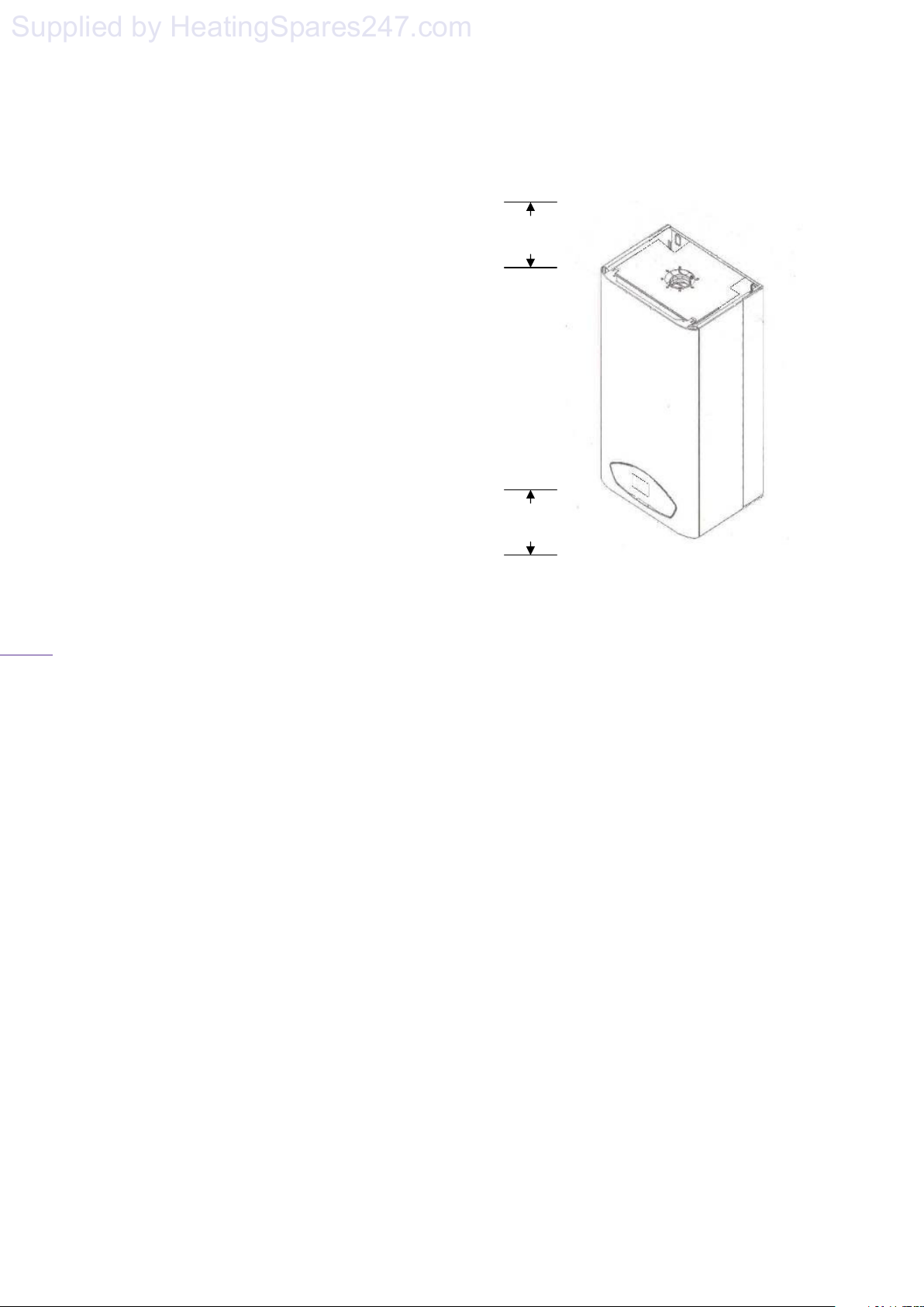
solaris 24PC, 30PC
Supplied by HeatingSpares247.com
42
IMPORTANT INFORMATION.
The Heat Line™ boiler is a high efficiency gas
fired boiler and represents the highest level of
technology found in today’s gas boiler market.
In order to maintain peak efficiency along with
optimum performance and reliability it is
essential that the boiler be serviced at least
once per year by a competent person such as a
CORGI Registered Engineer.
All C.O.R.G.I. Registered Installers carry a
C.O.R.G.I. ID card and have a registration
number, which should be recorded and entered
on your benchmark log book. You can check
your Installer registration by contacting
C.O.R.G.I. on 01256 372300
The boiler's 'Log Book' must be completed at
each Service visit.
GAS SAFETY (INSTALLATION AND
USE) REGULATIONS
It is a legal requirement that all gas appliances
must be installed and serviced by a competent
or C.O.R.G.I. registered person in accordance
with the above regulations. Failure to install or
service gas appliances correctly may
invalidate your guarantee and could lead to
prosecution. It is in your interest and that of
safety to ensure compliance with the law.
For electrical safety the boiler must be earthed
and protected by a 5 -amp fuse.
Note. In the event of a fault the appliance
should not be used until a competent person
has corrected the fault.
VENTILATION
For maintenance and safety purposes, the
boiler has been installed with a minimum
space of 200mm above, 300mm below,
600mm to the front and 20mm to either side of
the boiler case. It is essential that this space is
not restricted by the addition of shelves etc.
fitted above or below the boiler, or to the
boiler sides. See section 6 for detail. Do not store
flammable material or liquids near the boiler.
GENERAL DESCRIPTION OF THE
BOILER
The boiler is a combined domestic hot water and
central heating appliance. Its internal control unit
electronically provides direct burner ignition and
combustion supervision along with continuous
modulation of the burner’s gas supply.
By means of a manual switch the boiler can be set
to operate in one of two operating modes,
domestic hot water only or domestic hot water and
central heating.
DOMESTIC HOT WATER MODE:
When hot water demand is requested, by the
opening of a hot water faucet, the boiler will fire
automatically. An integral pump is then energised
and hot water from the boilers primary circuit is
circulated through the secondary heat exchanger,
allowing the instantaneous transferral of heat to
the incoming cold water. The secondary heat
exchanger is protected against an internal build up
of lime scale by limiting the hot water
temperature at the tap to a maximum of 64°C. Hot
water will continue to flow through the tap until
no longer required. When the demand for hot
water ceases the integral pump may continue to
run for a short while to dissipate any excess heat
Page 42
Page 44
solaris 24PC, 30PC
Supplied by HeatingSpares247.com
44
within the boiler.
DOMESTIC HOT WATER AND
CENTRAL HEATING MODE:
When heating demand is requested the boiler
will fire automatically. An integral pump is
then energised and hot water from the boilers
primary circuit is circulated around the
heating systems pipe-work and radiators. The
heat output from the boiler is automatically
adjusted by the boiler’s internal control unit to
match the heating demand. As the water
temperature of the heating system increases
the gas input to the burner decreases,
conserving energy and increasing efficiency.
When the demand for heating no longer exists,
either the room thermostat is satisfied or the
heating period has ended, the burner will shut
down and the boiler will revert to stand-by,
waiting to respond to the next heating
demand. The integral pump may continue to
run after shut down for a short while to
dissipate any excess heat within the boiler.
Please Note. When domestic hot water is called
for during the heating mode, the boiler will
automatically revert to domestic hot water
mode until the demand for hot water ceases.
NOTE: Depending on the boiler set up there
may be a delay of 45secs before the boiler refires.
Figure 2
ACCESS TO THE BOILER CONTROLS
The boiler controls are found behind the control
panel door, sited at the bottom of the boiler’s front
case. To open: press the doors retaining push
catch just above the display screen. (figure 2)
BOILER CONTROLS
The function and operation of the main controls
located on the control panel fascia (figure 3) is as
follows:
(Function switch.) This is the boilers
1.
main operating switch. In the
position the boiler is in stand-by mode
and power supply is ON. For the boiler to
operate the switch must be in the
2. (Central Heating temperature control.)
3. (D.H.W. temperature control) The
position.
When switched to the
boiler will operate only to supply
domestic hot water. (Summer use) For
the boiler to operate to give both central
heating and domestic hot water the switch
must be in the
The position of this control dial will
determine the temperature of the water
delivered to the radiators. The water
temperature can be set from a minimum
of 30º C (anticlockwise stop position) to a
maximum of 85º C (clockwise stop
position.)
position of this control dial will
determine the temperature of the
domestic hot water delivered to the taps
or shower unit. The water temperature
can be set from a minimum of 35ºC
(anticlockwise stop position) to a
maximum of 64ºC (clockwise stop
position.)
position the
position.(Winter use)
or
Page 43
Page 45
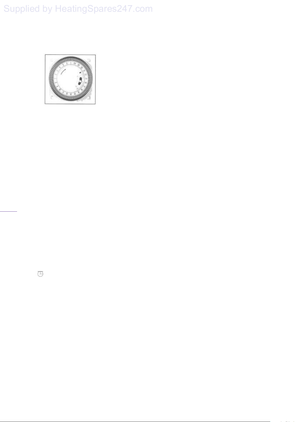
solaris 24PC, 30PC
Supplied by HeatingSpares247.com
44
Figure 5
The operational time periods may be set as
follows:
Rotate the clock actuator mechanisms
clockwise, by hand, until the small black
triangle indicates the current time, see
figure 5. In figure 5, current time is 21:05.
The timer uses 24 hour format, e.g. the
time for 1pm the time is 13:00 hrs.
Select the "On" times by pushing the black
tappets to the outside.
Select the 'Off' times by pushing the black
tappets towards the centre of the clock.
E.g. The clock shown in diagram 2 is set as
follows:
The clock operation can be set by a selection
switch.
The switch has 3 positions:
1 (Up) position: The boiler is controlled by the
function switch (Item 1 in Figure 3) and
allows continuous operation.
(Mid) position: The boiler heating circuit is
controlled by both function switch and clock
tappets, whilst hot water is delivered on
demand.
0 (Down) position: The boiler is off,
independent of the function switch.
FROST PROTECTION
The boiler has a built in frost protection device
that protects the boiler from freezing. If the
boiler is to be left and there is a risk of frost,
ensure that the gas and electrical supplies are
left connected. The frost protection device will
light the boiler when the temperature of the
boiler water falls below 6
o
C. When the
o
temperature reaches 15
C, the boiler will shut
down.
Note: This device works irrespective of any room
thermostat setting and will protect the boiler, but
not necessarily the full system. Ensure that
vulnerable sections of the circuit are adequately
lagged.
ANTI PUMP SEIZURE
Note the pump will occasionally operate
automatically in order to avoid seizure. See Daren
for time specification
SYSTEM PRESSURE.
On installation your installer will have filled the
boiler and system to its effective working
pressure. The boiler's pressure sensor should be
regularly checked on the LCD to ensure that this
pressure is maintained between 1 and 2 bar. If
there is a significant loss in pressure the boiler
will lock out. The system may be re-charged by
opening the filling loop to charge the system back
up to 1.5bar as indicated on the LCD panel. DO
NOT OVERCHARGE THE BOILER
PRESSURE BEYOND 2BAR AS THE BOILER
WILL NOT OPERATE. The filling loop, a
flexible hose with two valves, should be located
below the boiler connecting the second pipe from
the right to either one of the outer pipes, see
figure 10 on page 19. DO NOT CLOSE ANY
OF THE FOUR VALVES DIRECTLY
CONNECTING TO THE BOILER. If the boiler
frequently loses pressure then your installer
should be consulted.
Page 45
Page 46

solaris 24PC, 30PC
Supplied by HeatingSpares247.com
45
OPERATING THE BOILER
Prior to operating the boiler, check that the
pressure reading, on the LCD panel, lies
between 1 and 2 bar.
Set the boiler's 'Central Heating' and 'Domestic
Hot Water' temperature controls to maximum
by turning fully clockwise and set the external
'Room Thermostat' (if fitted) to maximum. (To
set the room thermostat refer to its
manufacturer's instructions.)
Switch the boiler’s functional switch to the
position. The boiler's integral control unit
will now automatically carry out pre-ignition
safety checks before finally igniting the
burner.
The 'Central Heating' and 'Domestic Hot
Water' temperature controls and 'Room
Thermostat' can now be set to the desired
temperature settings.
When a demand for heat no longer exists, the
burner will automatically shut down but the
green 'Boiler Stand by' indicator will remain
alight.
The boiler will be ready for the next heating
demand.
CLEANING
The boiler casing may be cleaned with a damp
cloth followed by a dry cloth to polish. Do not
use abrasive or solvent cleaners.
FURTHER ADVICE
For further information or advice (UK) contact
Heatlin
TM
:
Service please call: 0870 777 8341
Spares please call: 0870 777 8402
Technical assistance please call: 0870 777 8318
Or by E mail at our Web Site on
www.heatline.co.uk
Page 46
Page 47

solaris 24PC, 30PC
Supplied by HeatingSpares247.com
46
OPERATING THE BOILER
Prior to operating the boiler, check that the
pressure reading, on the LCD panel, lies
between 1 and 2 bar.
Set the boiler's 'Central Heating' and 'Domestic
Hot Water' temperature controls to maximum
by turning fully clockwise and set the external
'Room Thermostat' (if fitted) to maximum. (To
set the room thermostat refer to its
manufacturer's instructions.)
Switch the boiler’s functional switch to the
position. The boiler's integral control unit
will now automatically carry out pre-ignition
safety checks before finally igniting the
burner.
The 'Central Heating' and 'Domestic Hot
Water' temperature controls and 'Room
Thermostat' can now be set to the desired
temperature settings.
When a demand for heat no longer exists, the
burner will automatically shut down but the
green 'Boiler Stand by' indicator will remain
alight.
The boiler will be ready for the next heating
demand.
CLEANING
The boiler casing may be cleaned with a damp
cloth followed by a dry cloth to polish. Do not
use abrasive or solvent cleaners.
FURTHER ADVICE
For further information or advice (UK) contact
Heatlin
TM
:
Service please call: 0870 777 8341
Spares please call: 0870 777 8402
Technical assistance please call: 0870 777 8318
Or by E mail at our Web Site on
www.heatline.co.uk
Page 46
Page 48
Supplied by HeatingSpares247.com
Nottingham Road,
Heatline
Belper,
Derbyshire,
DE56 1JT
Tel: 01773 596 099
Fax: 01773 828 123
Email: [email protected]
 Loading...