

Page 1
Masonry Stove Builders
25 Brouse Rd., RR 5
Shawville, Quebec J0X 2Y0
(819)647-5092
HeatKit core assembly manual
AUTHOR NAME
Heat-Kit System
Modular Contraflow Masonry Heater Core
Assembly Manual
HK-22fo
22” Firebox with Front or Rear Bake Oven
Updated on November 21, 2017
Page 2
HeatKit core assembly manual
November 21, 2017
01
200
Standard Firebricks 4.5”x9”x2.5”
(2.5” dimension may vary.
Important: The 4.5” and 9” dimensions are important)
10
Firebrick “Splits” 4.5”x9”x1.25”
2 bags
“Mortar Mix” (ie., premixed with sand, as opposed to
“Masonry Cement”, which requires mason’s sand)
Material List (in addition to core components)
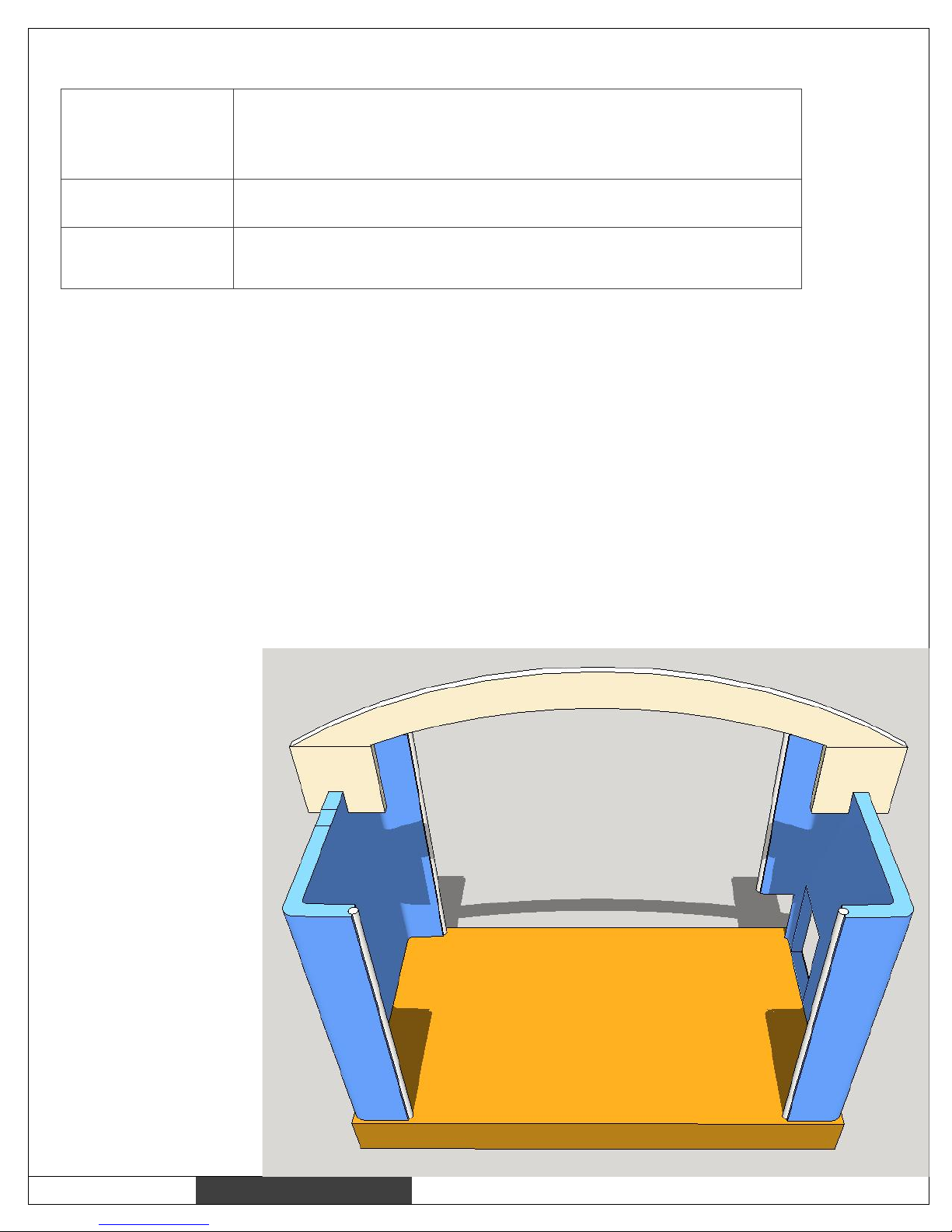
Assembling the Bottom End
The bottom end of a contraflow heater is the most complicated part of the whole job.
The two downdraft channels connect here, underneath the firebox. As well, the
chimney connection and the cleanout openings for the particular installation need to be
determined and located here.
We’ve removed as much of this complication as possible with the Heat-Kit system. The
insulated base slab allows you to do a dry layout first and make sure that everything is
located properly in relation to the chimney and the slab. As well, our thinwall refractory
castings simplify the job of making the necessary cutouts with a portable masonry saw
or a skilsaw.
If you take a little
extra time at this
stage, particularly
with the layout,
you'll avoid
problems later on.
Concrete tie wire
Page 3
HeatKit core assembly manual
November 21, 2017
02
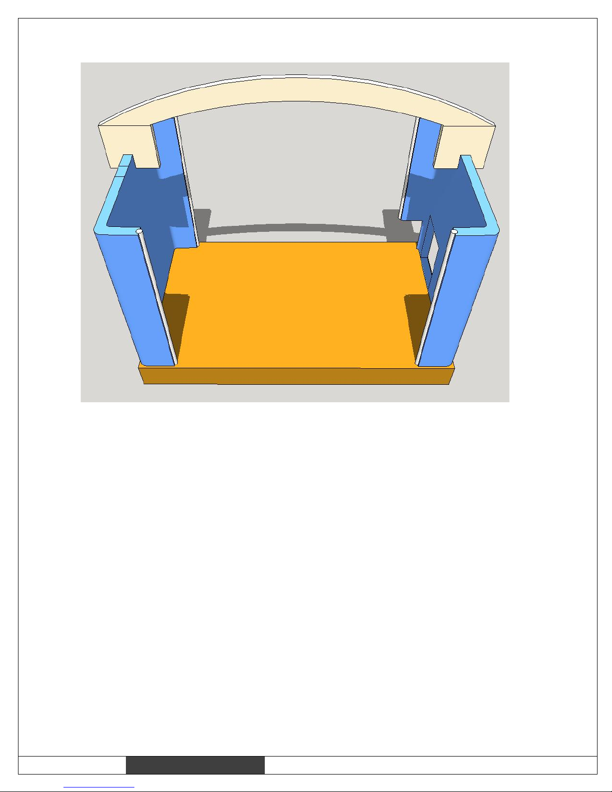
Position insulating base slab dry to determine layout for heater and chimney.
Mark final position at corners with a pencil.
Set insulating base slab in a 1/2" mortar bed, and level.
Determine location of chimney connection and location of 2 cleanouts, one for
each bottom channel. In the illustration above, a 7" x 11" cutout is shown in
the right channel, towards the back of the long side. Shown next to it is a
cutout for a 5.5" x 5.5" cleanout that will be in the facing.
The left side also requires a cleanout at the base (not shown).
Mark clean out cuts on the base channels. Mark chimney connection on base
channel.
Cut appropriate holes for chimney connection and for clean outs.
Set base channels dry. Use the plywood spacer to stabilize the channels as
shown. Bottom seam will be sealed later by mortar slush between channels
and facing.
Page 4
HeatKit core assembly manual
November 21, 2017
03
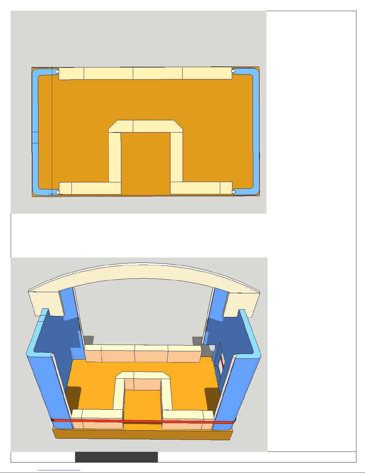
Brick Cuts:
For firebricks
standard sizes are:
full ---- 9"
3/4 ---- 6-3/4"
half ---- 4-1/2"
1/4 ---- 2-1/4"
Build connecting
channel, using
refractory mortar.
If there is a rear
chimney, leave opening
and span with flat bar
supplied. Notch bricks
to accept flat bars, thus
allowing you to
maintain thin joints.
1'-11 1/8"
1/2
1/4
1/2
1/4
1/2
Firebrick shiners at the rear are flush with outside of slab.
(Note: “shiner” = brick set on edge)
Outside-to-outside on the firebricks (front-to-back) is 1-11 1/8" as shown.
Once first course is set,
install velcro strap
(supplied with core kit)
to stabilize bottom.
Page 5
HeatKit core assembly manual
November 21, 2017
04
2 1/4"
1 1/2"
3"
1 1/2"
2 3/4"
1"
1/4"
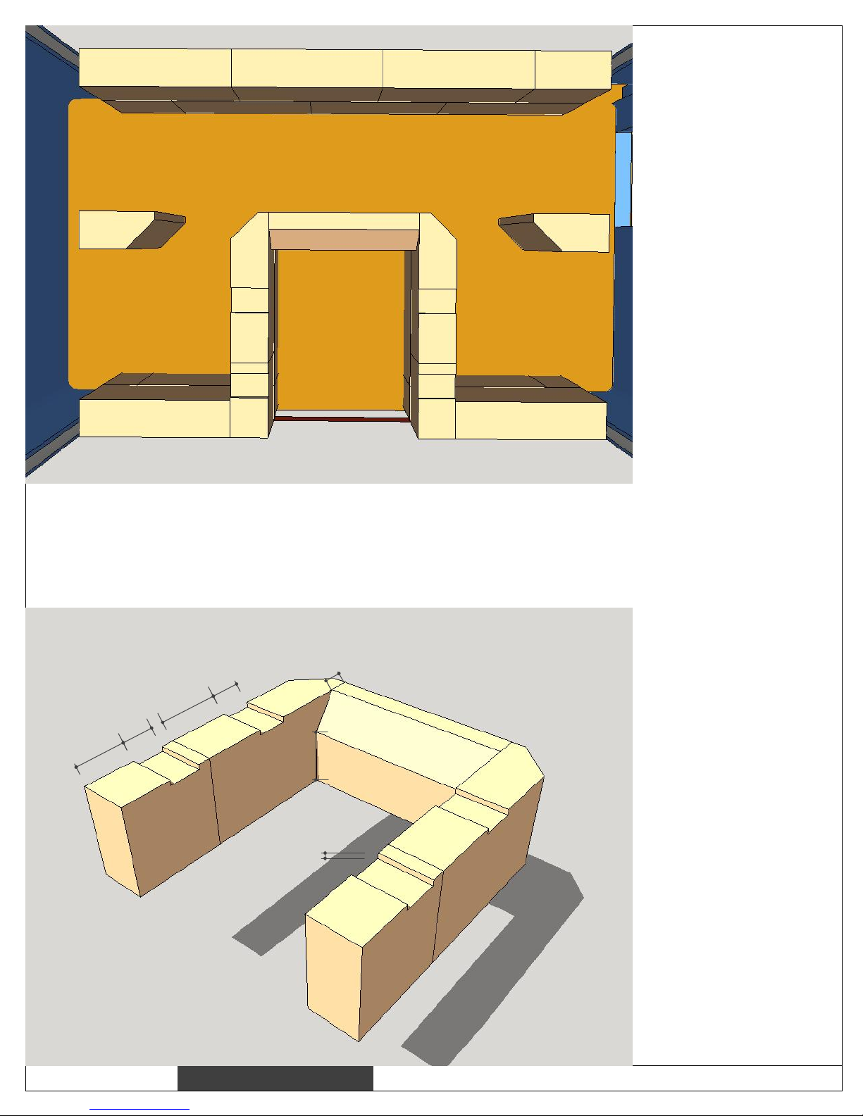
Second course.
Refer to isometric views on next page.
Cut 1/4" deep notches
for flat bars as shown.
Page 6
HeatKit core assembly manual
November 21, 2017
05
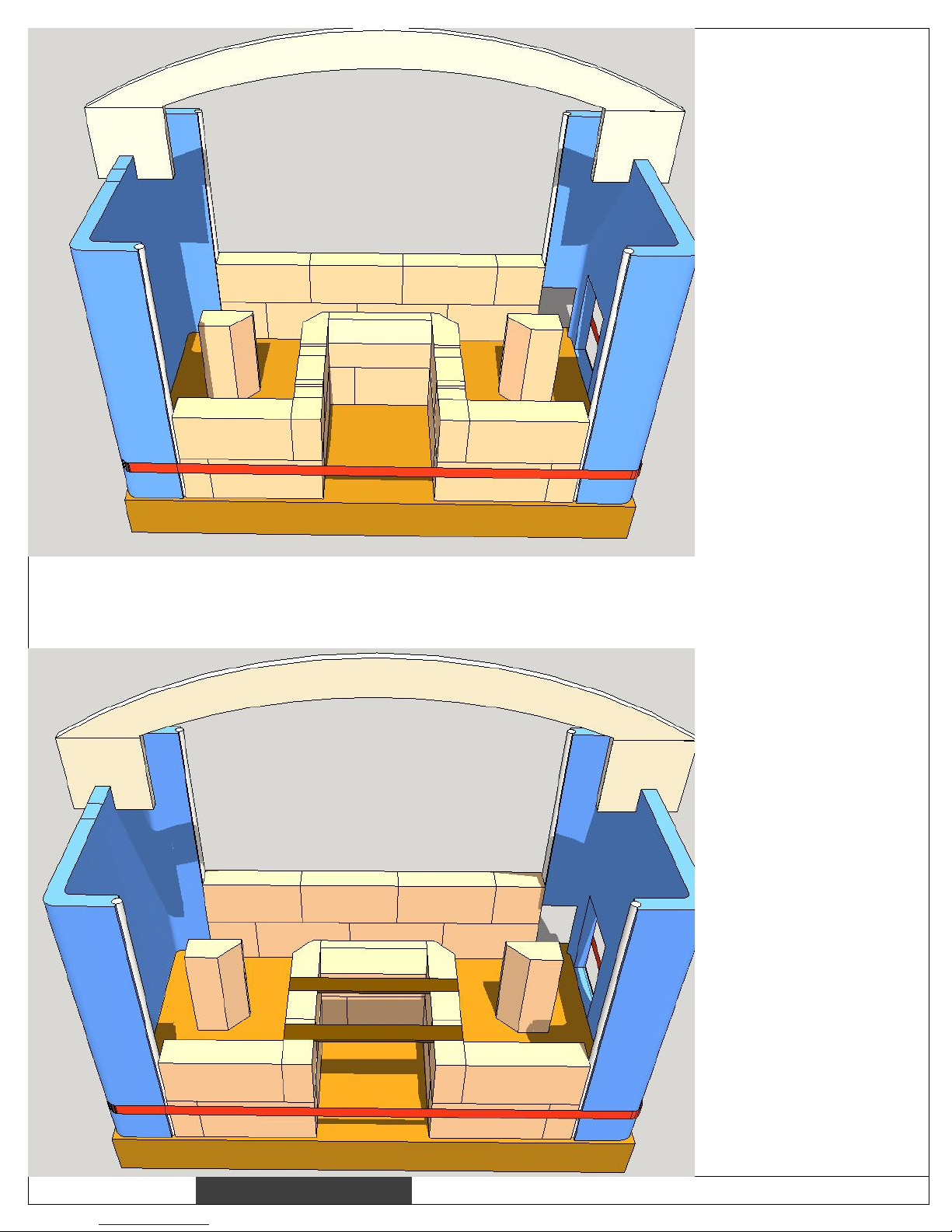
Set flat bars as shown.
You can use a
refractory mortar bed if
they need levelling.
Page 7
HeatKit core assembly manual
November 21, 2017
06
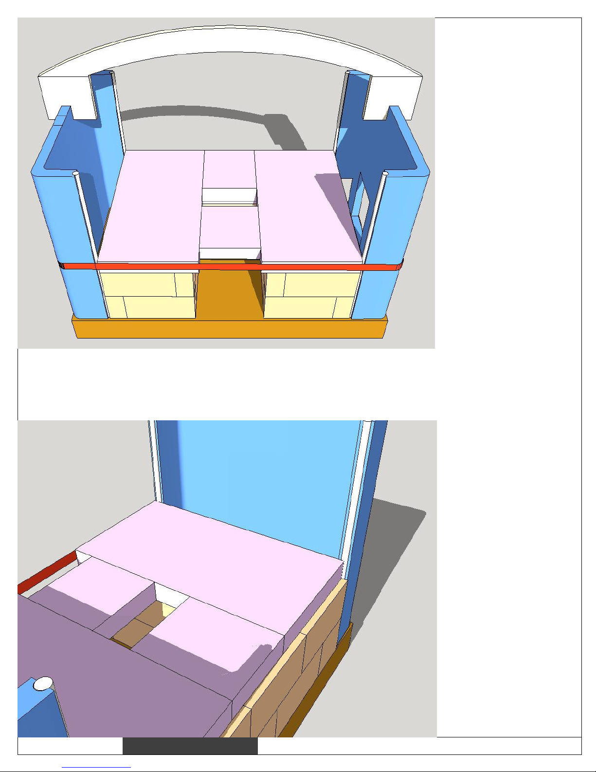
Set sub-floor slabs in
refractory mortar. Use
a thick bed to allow
some room for
levelling.
Refer to install video
https://vimeo.com/211
742460 at 2:15.
Raise the strap to the
level shown above.
This will stabilize the
channels enough that
you can remove the
plywood spacer.
This will give you
better access for
working
Set the slabs flush with the front firebricks.
Use the channel edges as a guide.
Note (below) that at the rear there will be a jump and the slabs are
not flush with the firebricks below.
Page 8
HeatKit core assembly manual
November 21, 2017
07
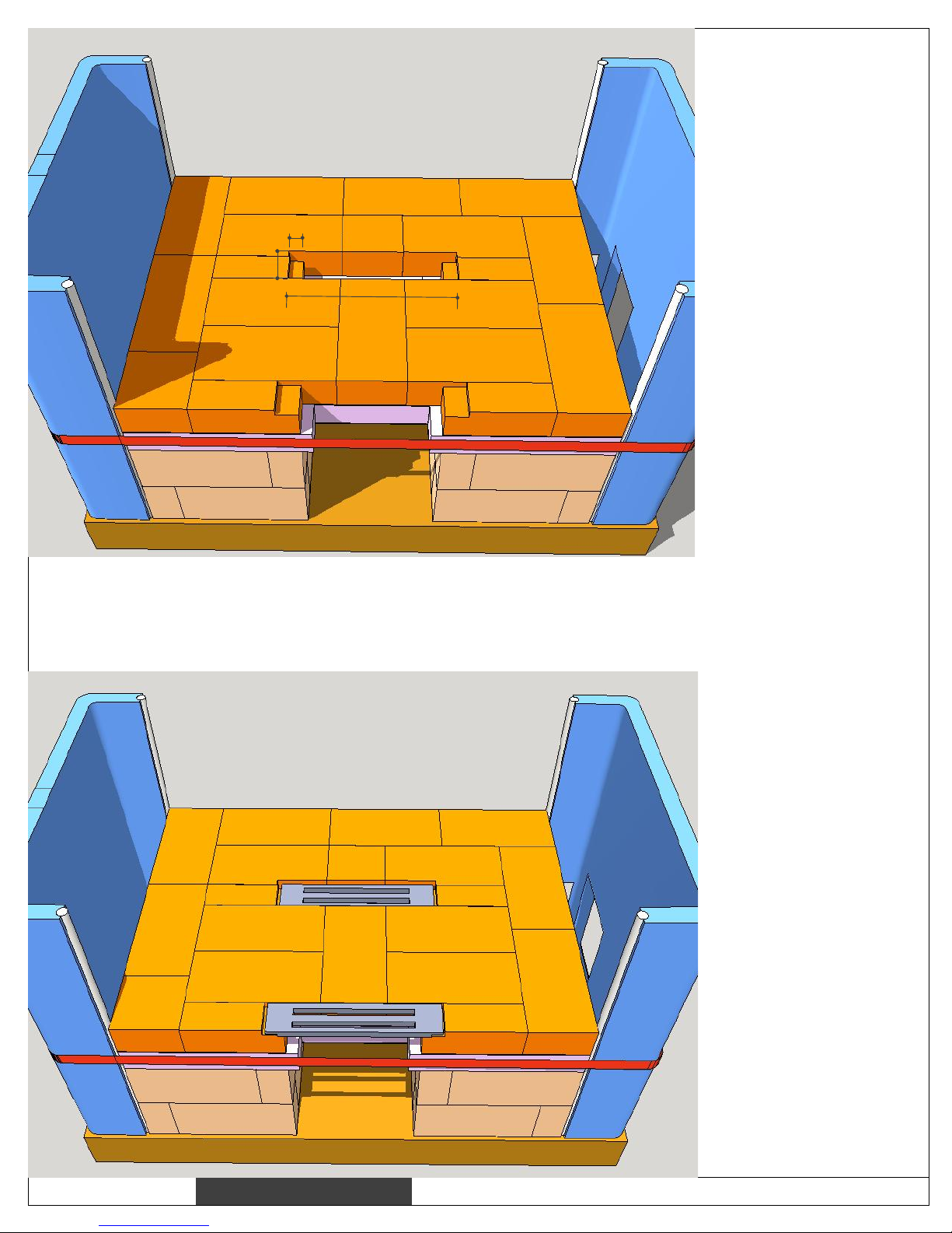
Do a dry layout of the firebricks for the firebox floor.
You are using standard shapes - 1/2's and soaps.
(Soap = firebrick ripped lengthways into two 9" x 2-1/4" pieces).
Cut the notches to fit the two grates.
2 3/4"
1'-0"
Set the floor bricks.
Line up the rear
corners with the slabs
below, using the
channels as a corner
guide for the rear
corners.
See next page for
notes on setting
firebricks with
refractory mortar.
1"
Page 9

HeatKit core assembly manual
November 21, 2017
08
Setting Firebricks
Firebricks are laid up with clay air setting refractory mortar (“Sairset”, or
fire cement) with thin joints. Only enough clay needs to be used to
completely fill the joint. No joint thickness needs to be built up - you are
only filling in gaps and irregularities between the bricks. Although masons
are used to trowelling firebricks, the best joints are obtained by dipping the
bricks into mortar that has been thinned to the right consistency. It looks
messy, but the cleanup is easy later with a sponge.
The Sairset that comes with the heater core kit is at trowelling consistency.
For dipping, you will need to thin it with water. A drill powered drywall mud
mixer works well for this. You can tell if the Sairset has the right
consistency by floating a firebrick in it. It will sink about half way. We like
to dip the bricks and also keep a margin trowel (small rectangular trowel)
handy for the odd bit of trowelling.
Assembling the Firebox
The firebox is laid up from standard firebricks. Standard firebricks are 4 ½”
wide by 9” long by 2 ¼” thick. The thickness will vary between 2 ¼” and 2
½” depending on the supplier. Since the Heat-Kit is designed around the
standard firebrick module, it is important to check the width and length of
your bricks beforehand, to avoid having to make modifications to the
assembly procedure.
The firebox consists of two shells of firebricks set on edge. This allows the
inner shell to be a field replaceable firebox liner. The firebrick installation
sequence has been numbered. By following this order, you maximize the
ability to “bury” odd lengths where they don’t show and reduce the
amount of precise cutting that you have to do. Note that full contact
between inner and outer shell is not required at the inside corners. Where
convenient, a little play right at the corner provides some expansion room
for the liner.
Page 10
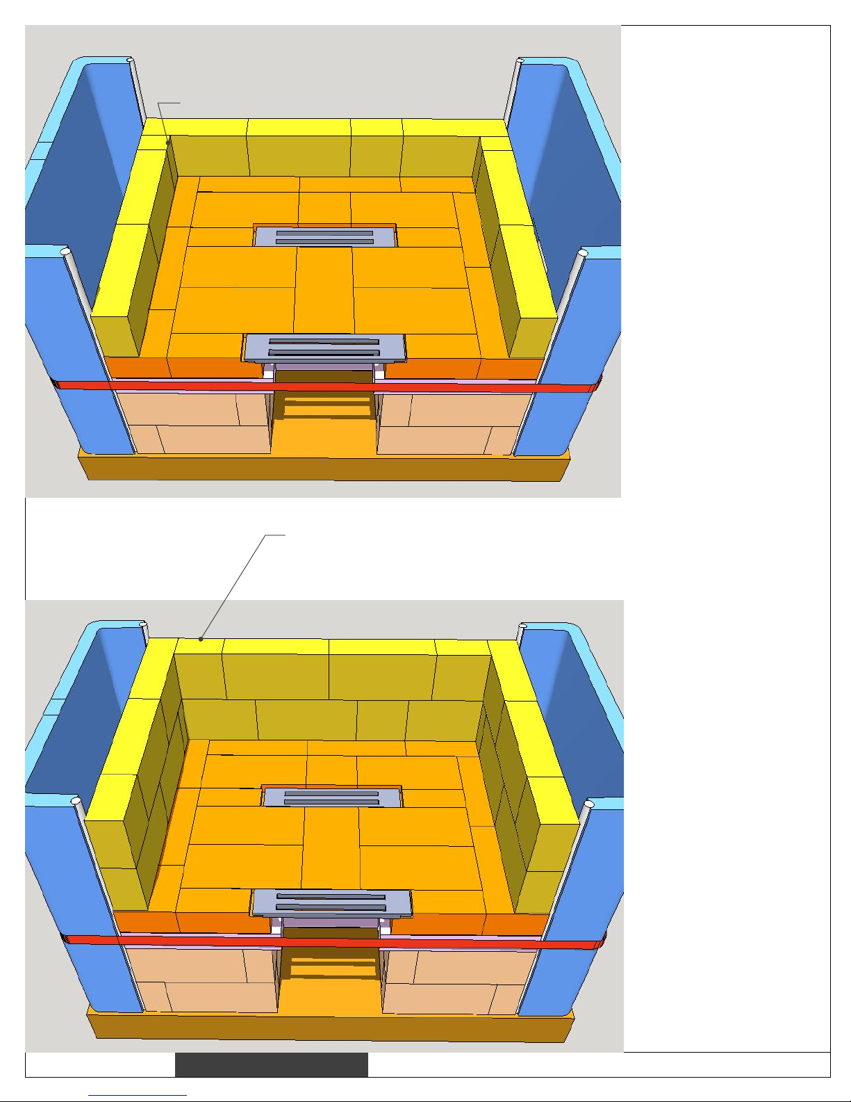
HeatKit core assembly manual
November 21, 2017
09
4-1/4"
2"
Lay out the firebox as
indicated, using air
setting refractory
mortar.
Non-standard cuts are
indicated by
dimensions
(2" and 4-1/4" here)
instead of the standard
firebrick shapes
ie., 1/4, 1/2, 3/4, full
Firebrick corners sit dry
against the fiberglass
rope gaskets.
Channel edges act as
corner guides.
Outer width of firebox
is 31 ½”.
4-1/4" if your firebricks are 2-1/4" thick
or 4" if your firebricks are 2-1/2" thick
Exact bond is
dependent on firebrick
thickness, generally
between 2-1/4” and 21/2”.
Front bricks on the
second course are
halves. Put the cut side
out (towards the front).
The grates are shown
for reference only.
Better to install them
at the end.
Page 11
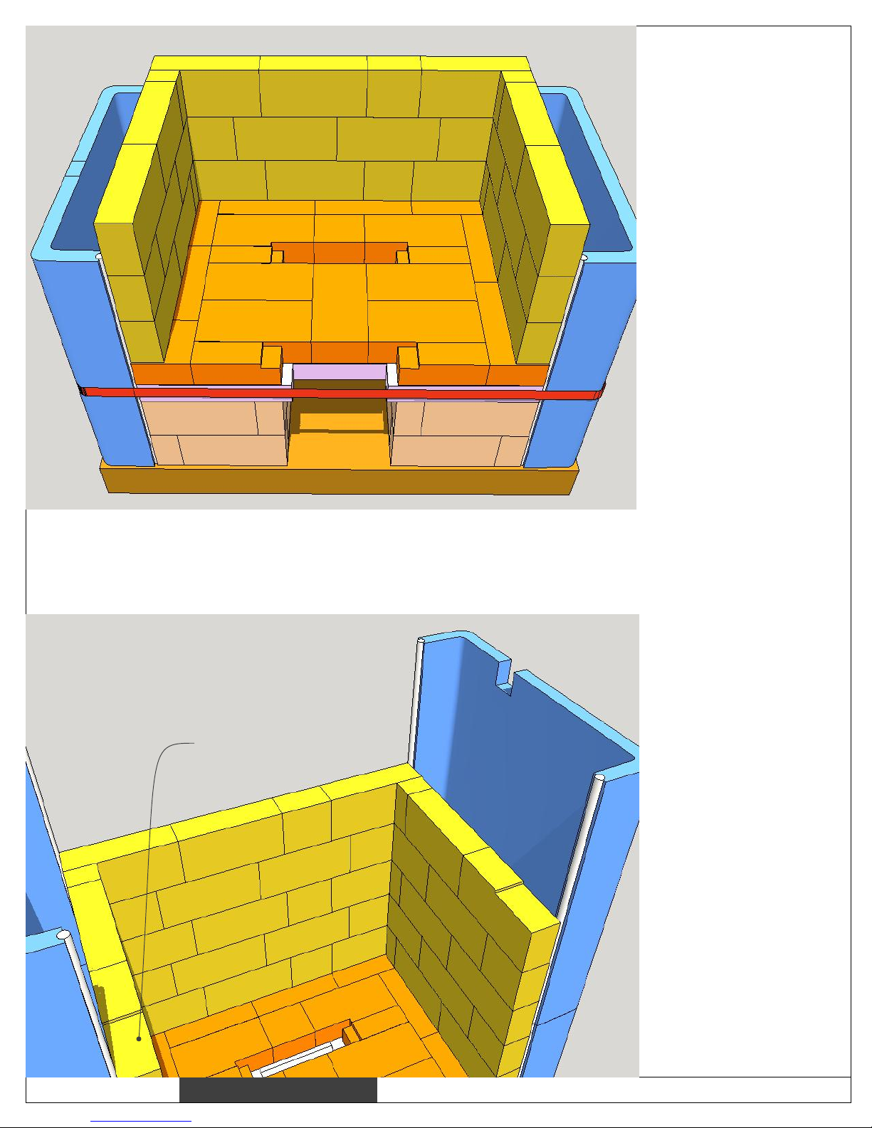
HeatKit core assembly manual
November 21, 2017
10
(Below):
Completed outer shell
of firebox.
Top front firebricks are
notched 1/4" x 4" for
firebox lintel.
Install next set of side
channels onto a
refractory mortar bed.
(see next page showing
plywood spacer).
Clean up any mortar
squeeze out inside the
channels.
Note the 2" x 2" notch.
This is a permanent
bypass, to help warm
up the chimney when
the heater is started
cold. It is located
wherever your chimney
is (right side towards
the rear in this
example).
Cut the notch before
installing the channel.
Just cut two vertical
kerfs, and you can pop
the piece out with your
brick hammer.
Notched
Page 12
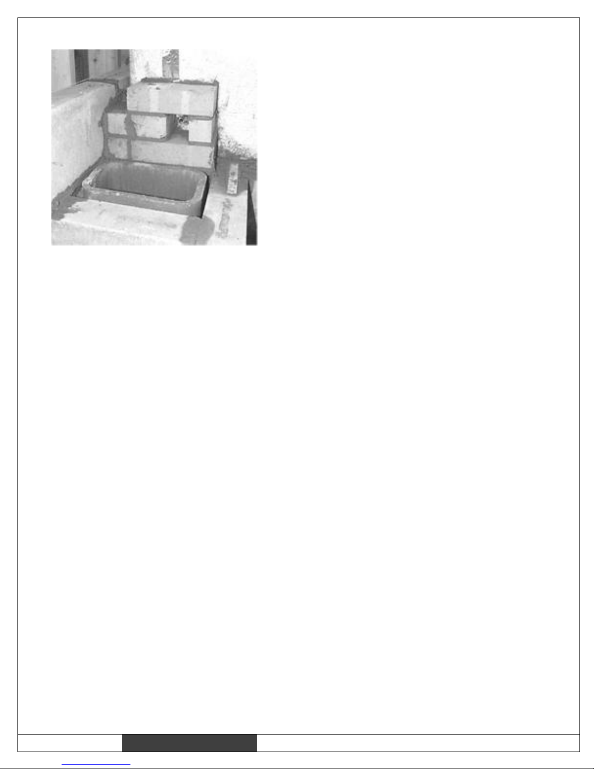
HeatKit core assembly manual
November 21, 2017
11
Gas slot details:
For easier heater startup during
difficult conditions (cold heater,
warm outside temperatures) we
highly recommend installing a gas
slot. This consists of a 2” X 2”
direct connect.
Cut a notch in the channel at the
appropriate location to line up
with the flue liner where the
chimney will be.
Later, when facing the heater,
create the direct connect to the
flue liner by using firebricks or
firebrick splits
Page 13
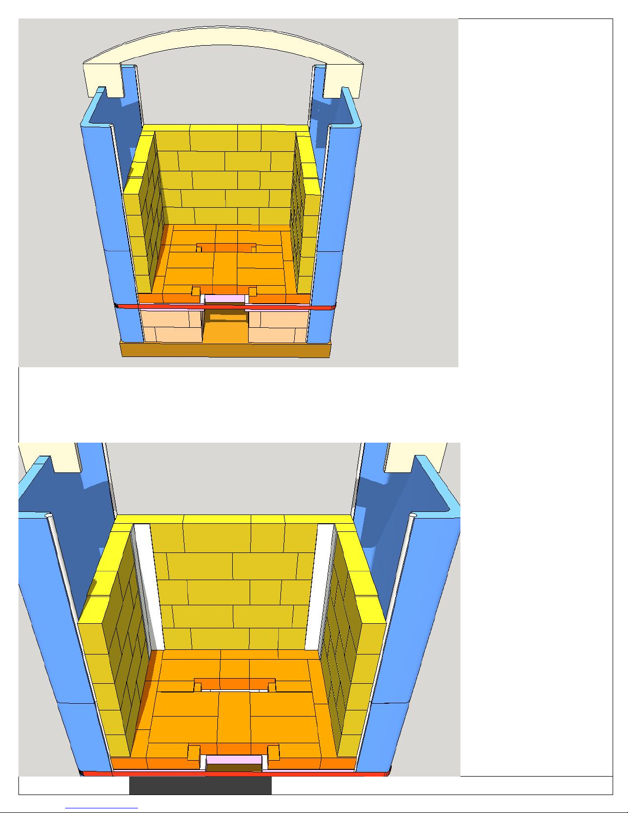
HeatKit core assembly manual
November 21, 2017
12
Install two 2-1/4"
strips of ceramic paper
(supplied) at the rear
corners.
A few light dabs of
refractory mortar will
hold them in place.
Page 14
HeatKit core assembly manual
November 21, 2017
13
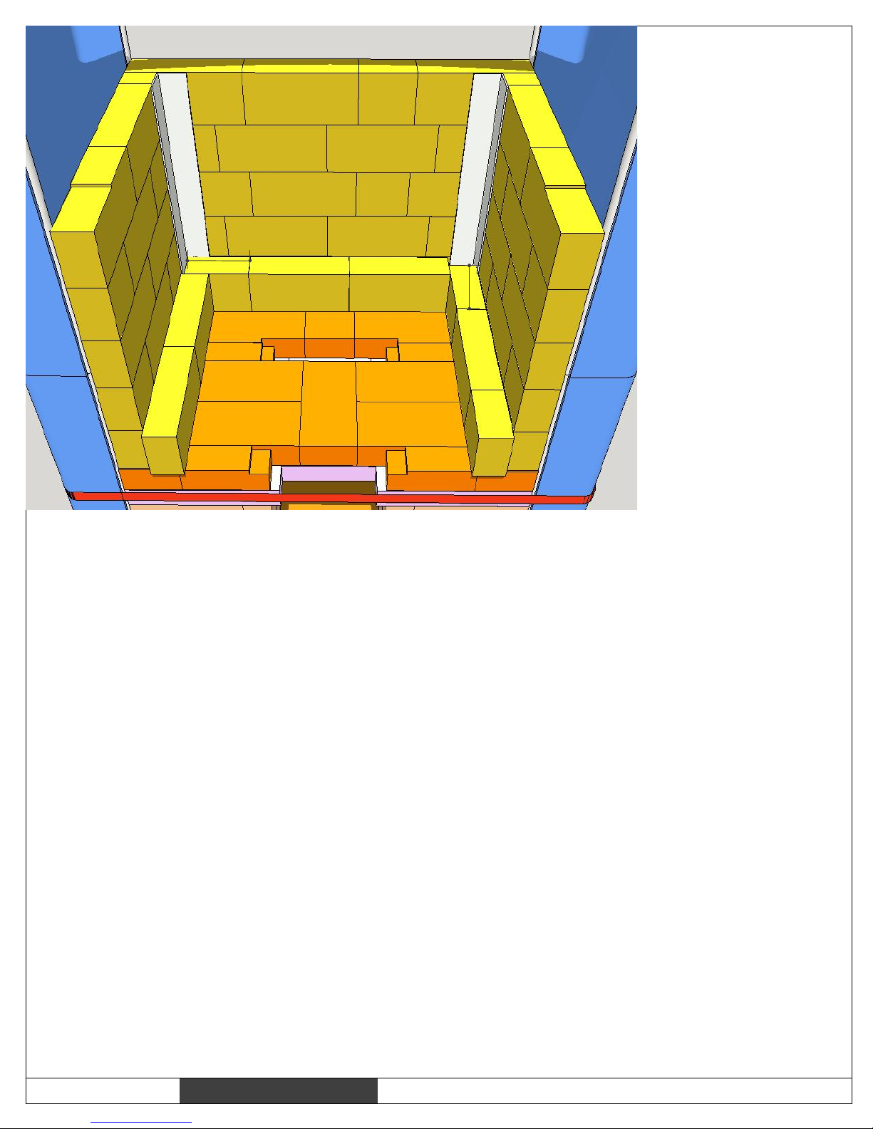
Begin inner firebox. Note that the bricks are left about 1/4" - 1” short
at the blind inside corners. The cut edges on these bricks are hidden.
On each course, you begin with the half brick at the front. Depending
on the thickness of your firebrick, it will project past the outer
firebox. This is OK.
However, for your first brick you do not know yet what this projection
will be.
Do a dry layout of the first course to determine the projection,
usually around 1/2".
The inner firebox is set dry against the outer firebox. There is no
mortar joint between the two fireboxes.
5 3/4"
5 3/4"
Page 15
HeatKit core assembly manual
November 21, 2017
14
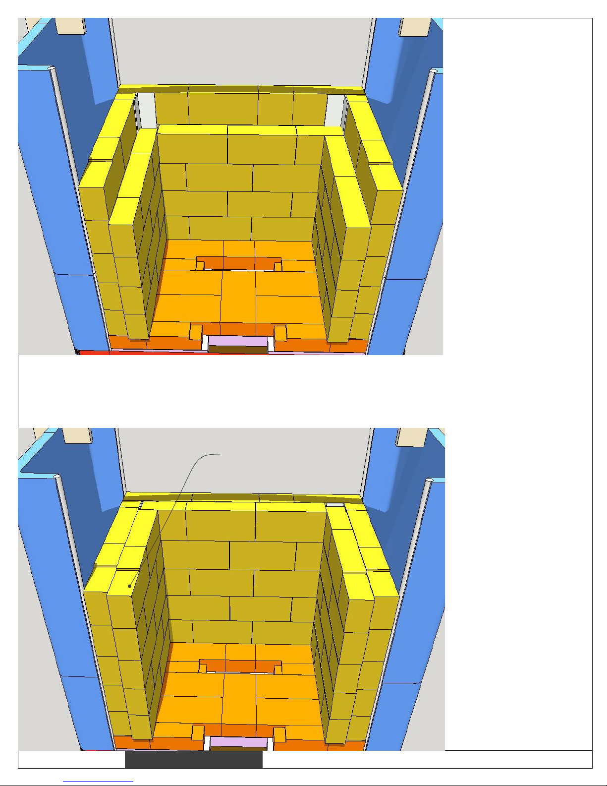
Your second course will be same as the fourth course, which is shown
here.
It is the same as the first course, except the half brick starts on the
left.
Notch top course of
firebox liner as shown.
Notches are
1/4” x 4-1/4”
Notch
Page 16
HeatKit core assembly manual
November 21, 2017
15
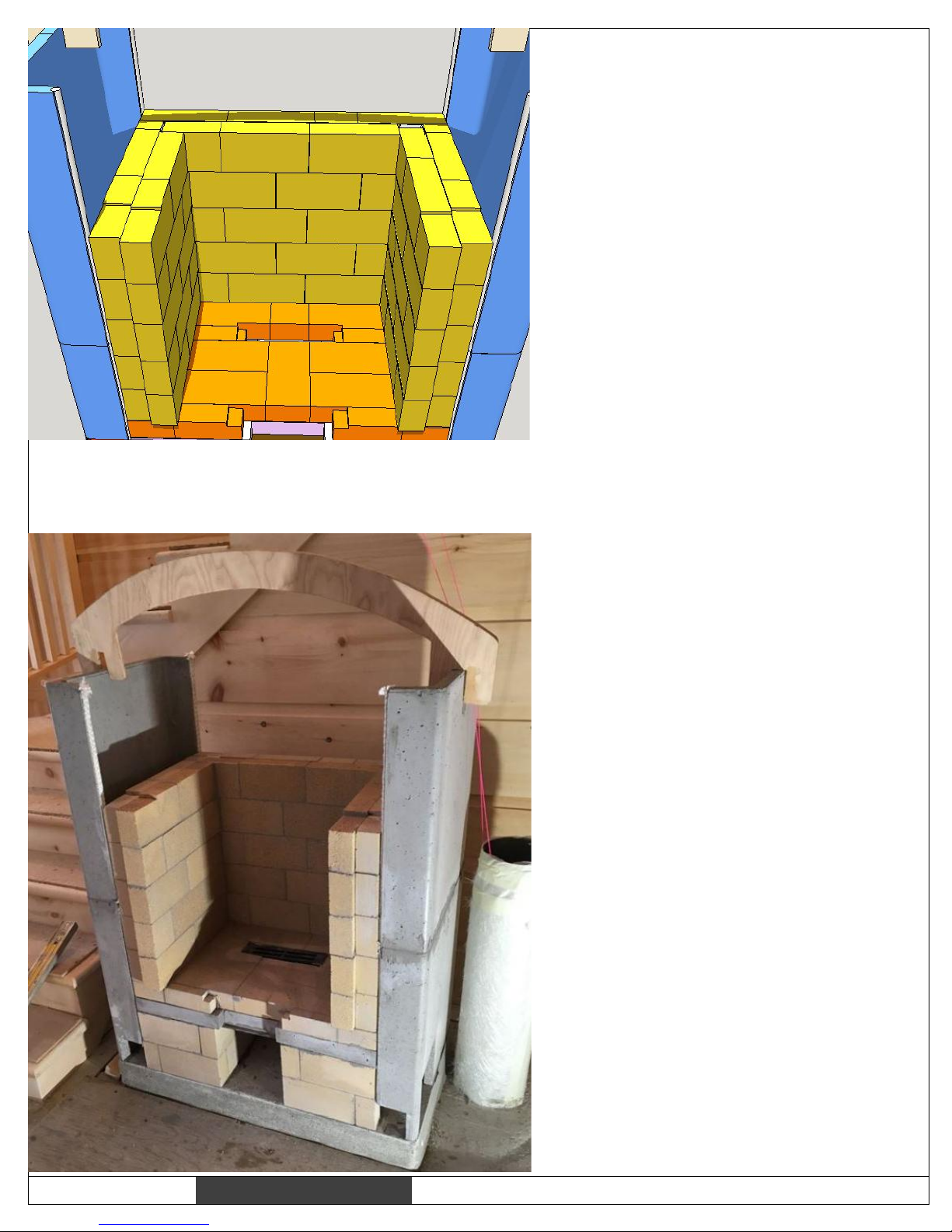
Immediately wash
down the firebox with
a sponge and a liberal
amount of water. Rinse
with clean water.
If this is done right
away, it is easy to get
a clean looking firebox.
Page 17
HeatKit core assembly manual
November 21, 2017
16
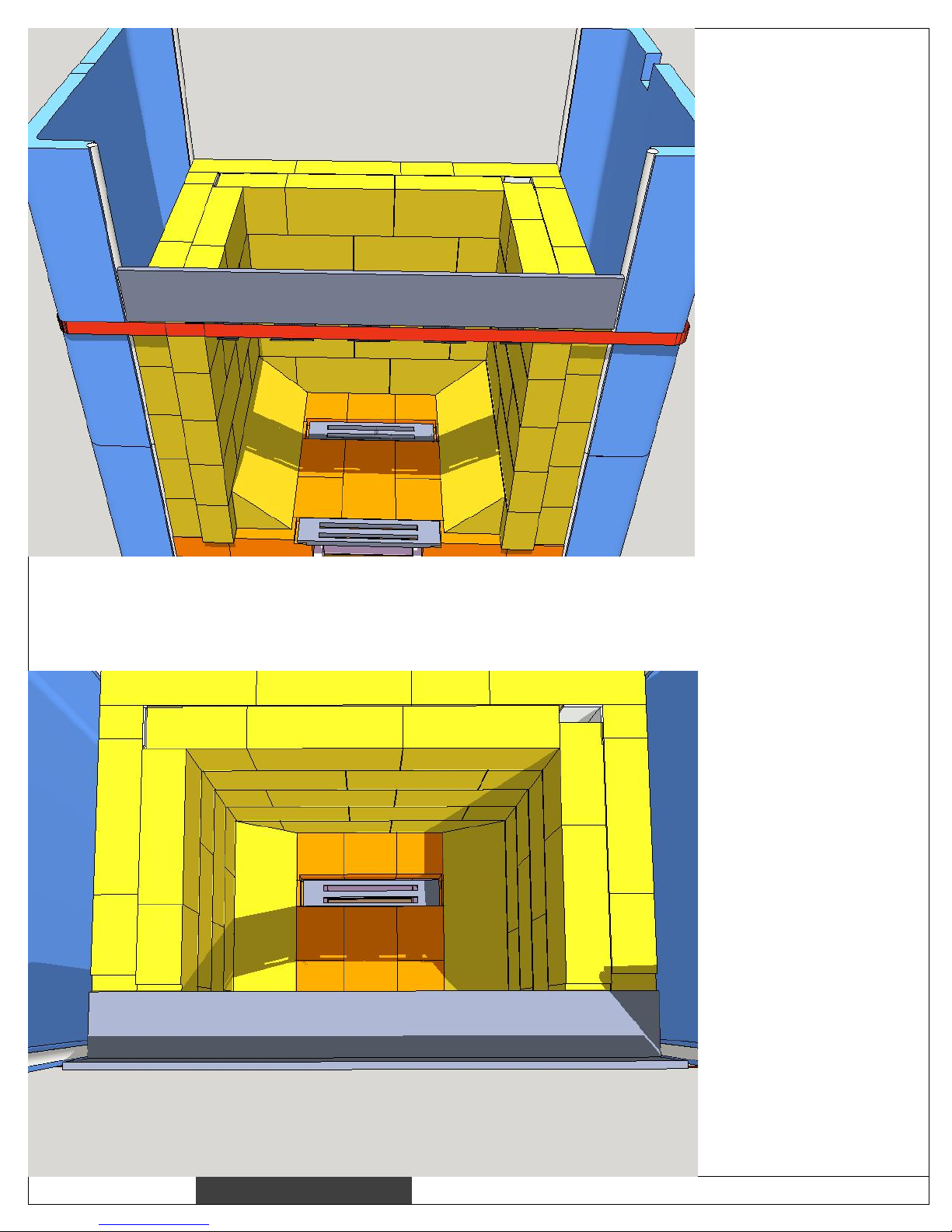
Install firebox lintel.
Use a refractory bed
under the ends if they
need levelling.
Vertical face is slightly
proud of channels, see
bottom illustration.
Raise strap as shown,
so that you can remove
the plywood spacer for
easier access.
The precast firebox
floor slopes are shown
for completeness.
However, it is better to
install them at the end.
Page 18
HeatKit core assembly manual
November 21, 2017
17
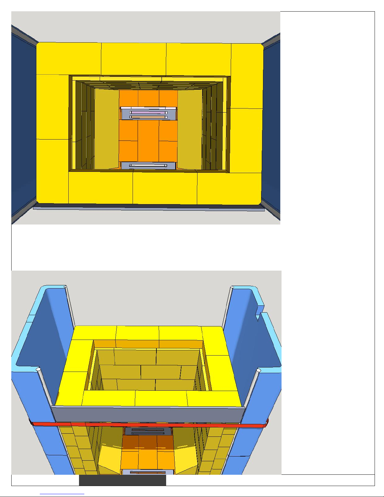
Building the Upper
Firebox:
Rear Bake Oven:
The drawings show a
front bake oven. For a
rear oven, reverse the
plan at this point. In
other words, flip the
remaining layout by
180 degrees.
If you have access to strapping tools, this course can be strapped as shown on the next page.
This is optional. If a strap is used, then round outside corners of bricks slightly.
The purpose of the strap is to transfer weight onto the outer firebox.
This allows the complete inner firebox to be removed, if necessary, rather than in sections.
For the bricks that sit
on the angle iron,
round their bottom
front edges slightly, to
allow a tighter fit
against the angle iron.
Leave about 1/16" gap
if you will be strapping
this course.
Page 19
HeatKit core assembly manual
November 21, 2017
18
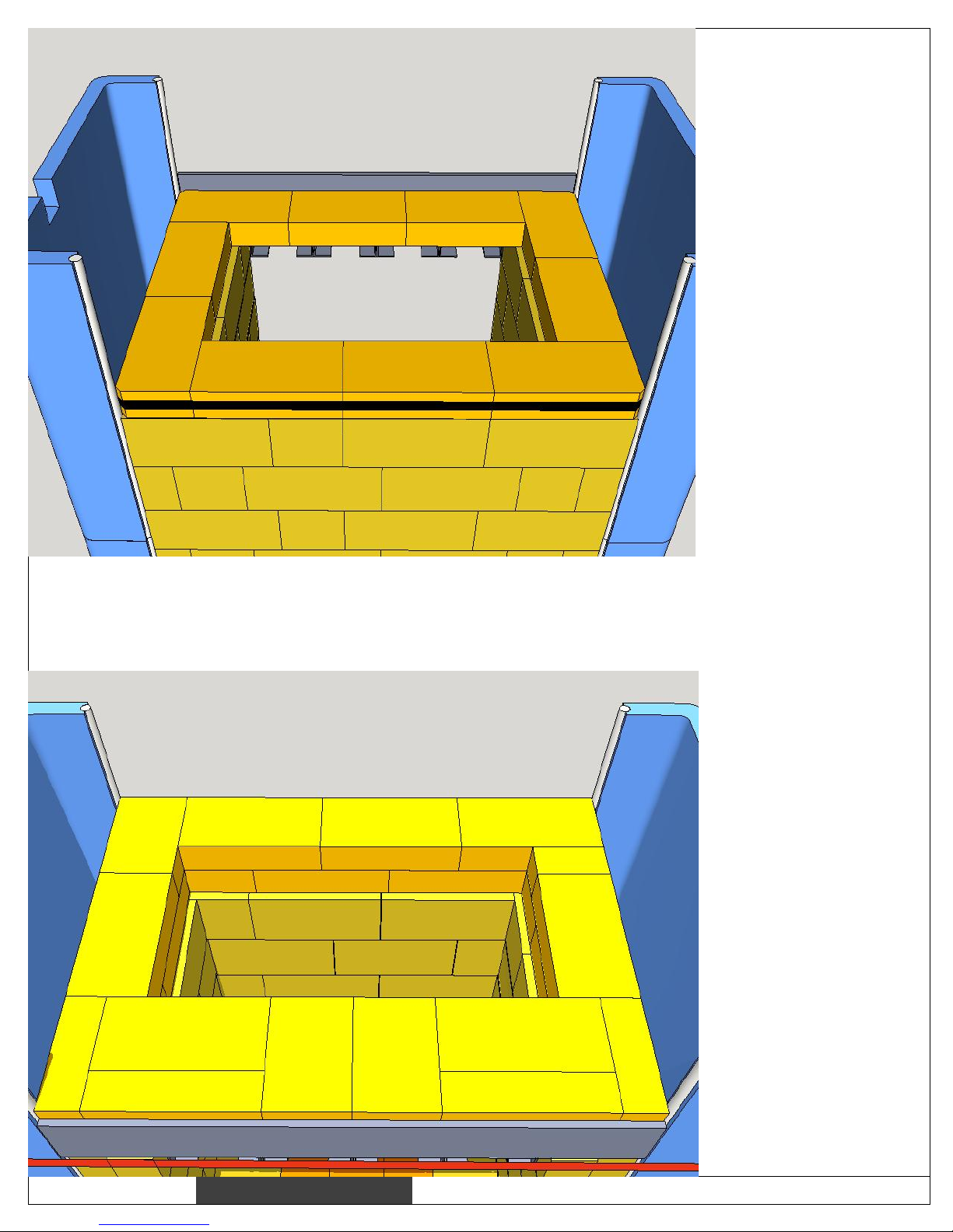
Course strapped with
5/8" steel strapping
(optional).
Strapping runs inside
the lintel, next to the
brick.
Next course layout.
Three 3/4 bricks
(6-3/4")
One 1/4 brick (2-1/4")
2 soaps (bricks ripped
lengthwise)
2 three-quarter soaps
(6-3/4" long)
3/4
1/4
soap
soap
3/4
soap
3/4
soap
3/4
3/4
Page 20
HeatKit core assembly manual
November 21, 2017
19
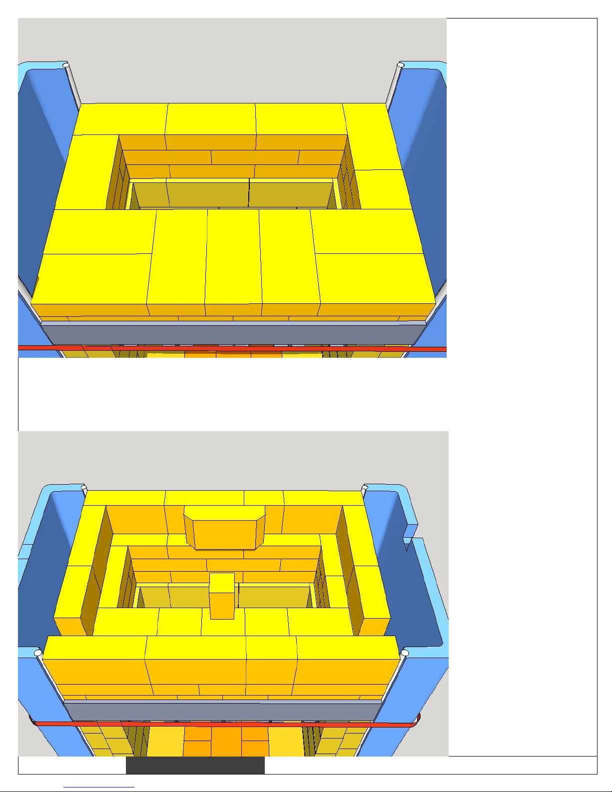
4-1/4"
3/4
3/4
4-1/4"
1/4
This is the course that
the oven floor will sit
on (see next
illustration).
For the portion that
will support the floor,
take extra care to level
the bricks. This will
make it easier to level
the floor.
Determine your high
spot, and work from
there. Use fat joints
under the lowest spot
if needed.
Page 21
HeatKit core assembly manual
November 21, 2017
20
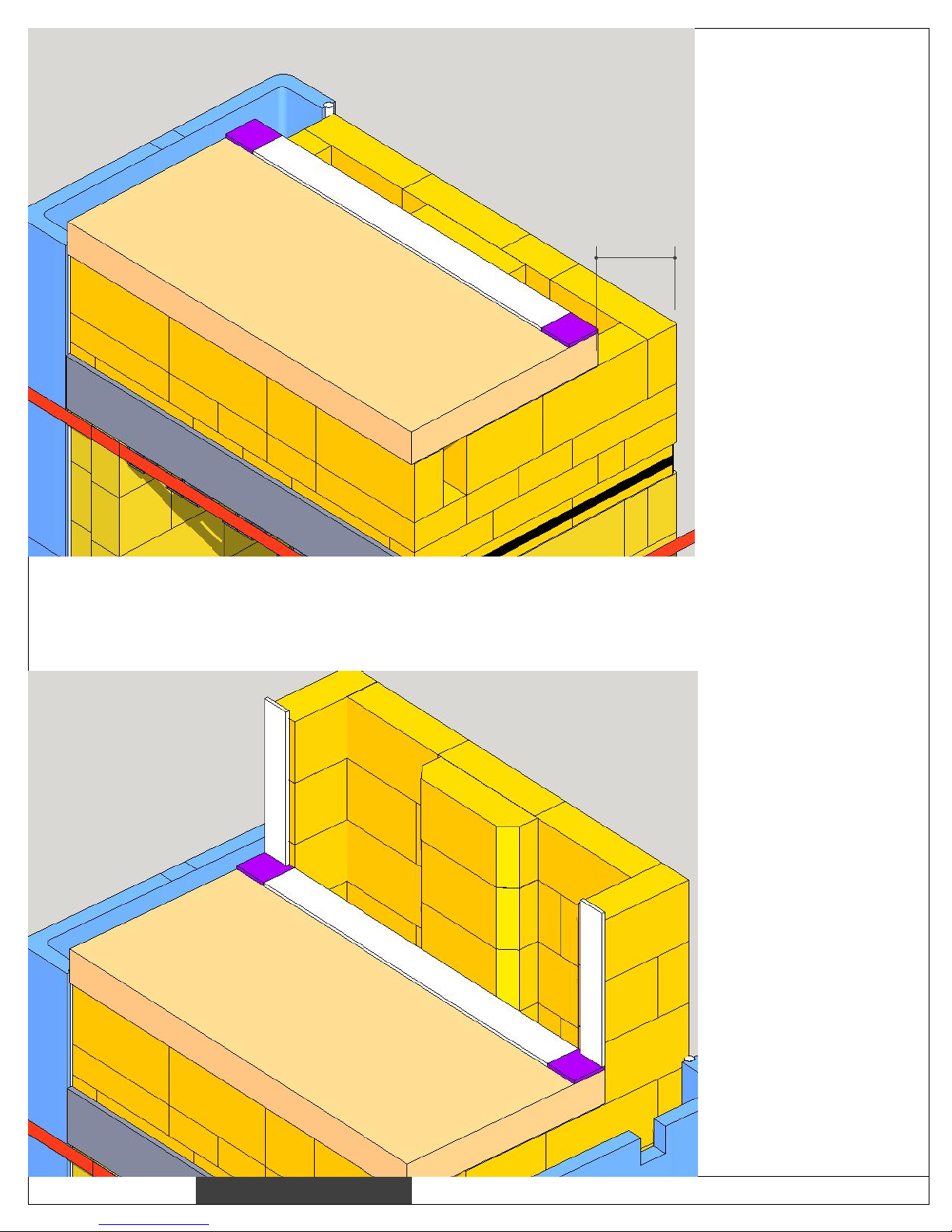
6 3/4"
(Side channel not
shown)
Set oven floor onto a
generous mortar bed.
Note that it will
overhang in the front
about 1/4"
Set it down carefully to
avoid mortar squeeze
out, to allow you some
room for levelling by
tapping down the high
spots.
Set the two metal
corner shims with the
location pins into the
predrilled holes.
Cut and set a strip of
2" wide ceramic paper
gasket where shown.
Build up the rear wall
as shown. The brick
bond shown works for
2-1/4" thick
firebricks.
If your bricks are
2-1/2" thick, trim one
of the full sized bricks
by 1/2".
For the stacked bricks
in the thickened
center, ensure full
mortar joints,
especially with the rear
wall. Rub the bricks
into the rear wall.
Add the two gasket
strips shown.
Page 22
HeatKit core assembly manual
November 21, 2017
21
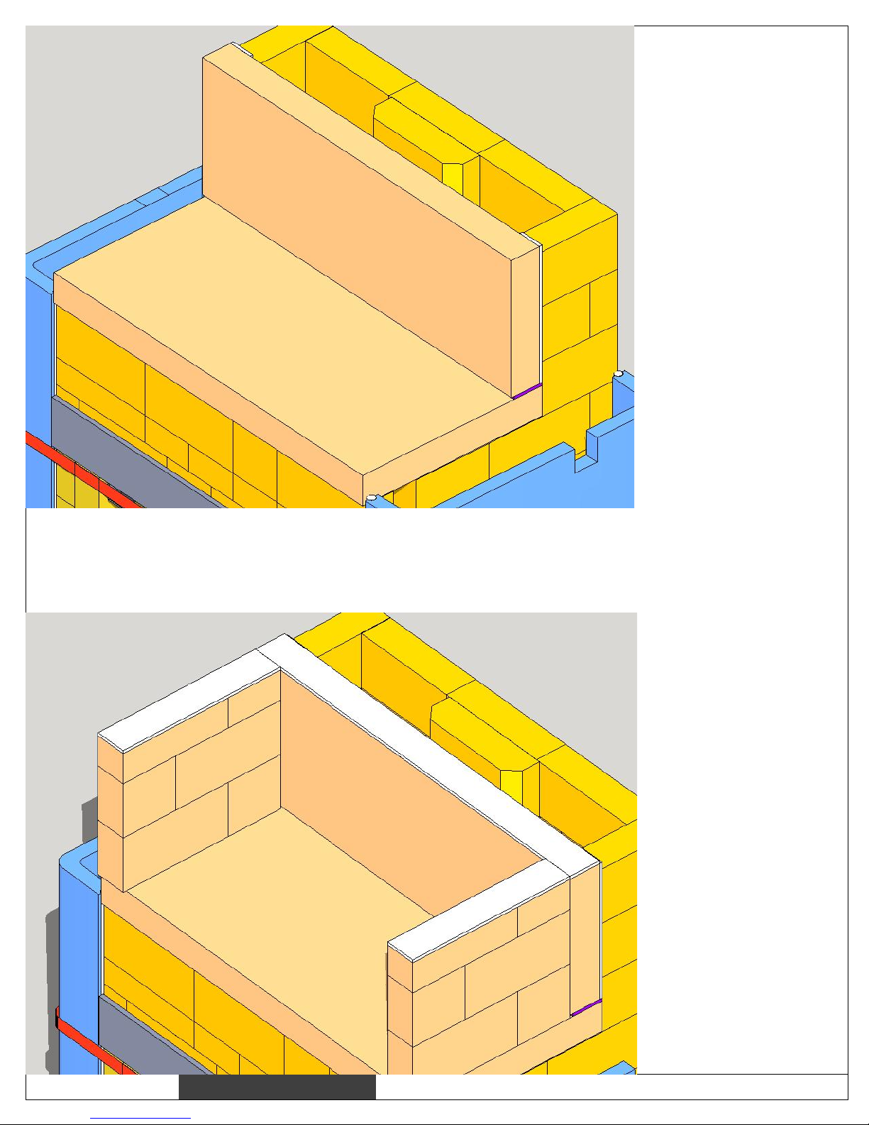
Set the rear wall dry.
Build up the sidwalls
from firebrick shiners.
Use a mortar joint
against the rear wall.
Install gasket as
shown. Use a thin coat
of refractory mortar to
glue the gasket, to
avoid movement when
you install the ceiling
slab.
Page 23
HeatKit core assembly manual
November 21, 2017
22
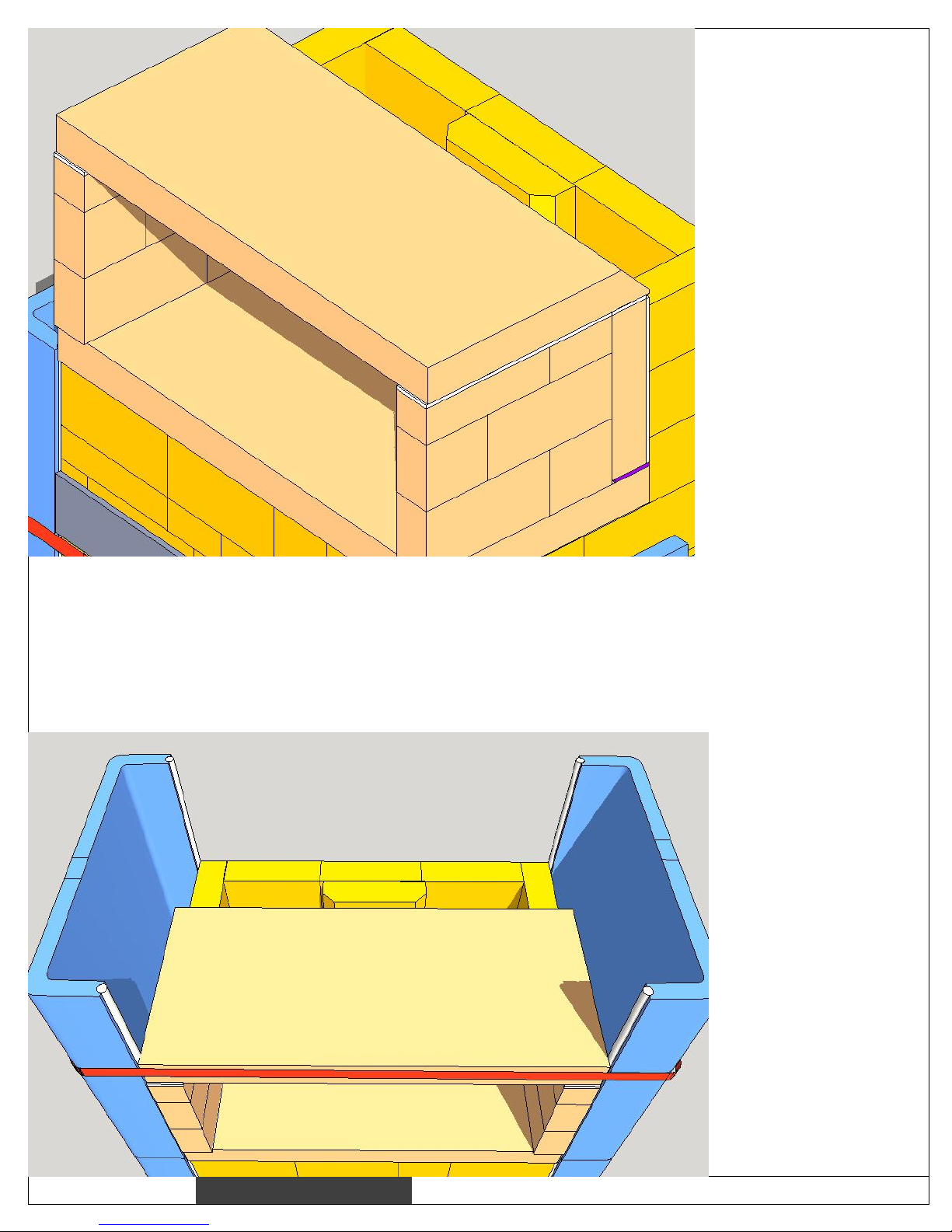
Install oven ceiling dry
onto ceramic paper
gaskets.
Install upper channels
onto a refractory
mortar bed.
Clean up any mortar
squeezeout inside the
channel.
The channels are
marked with an arrow
indicating the "up"
direction.
Add the second
temporary strap to
stabilize the channels.
Page 24
HeatKit core assembly manual
November 21, 2017
23
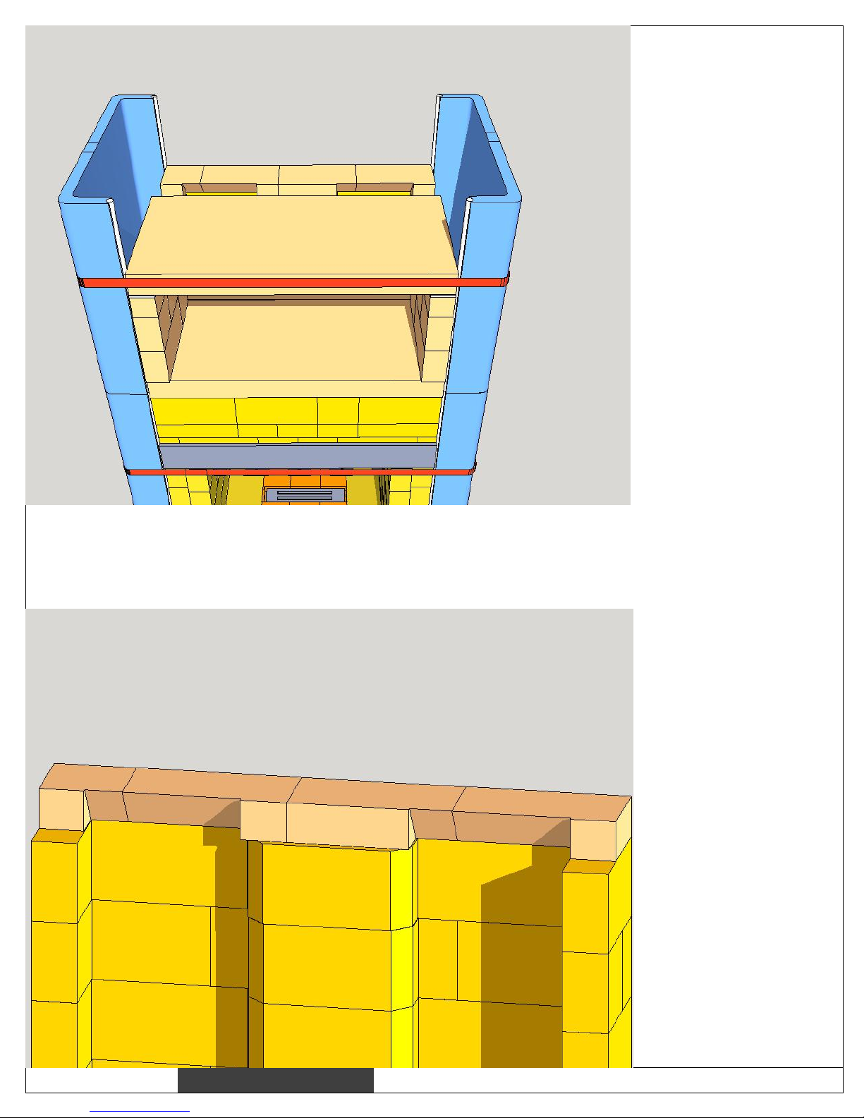
Build the transition
piece at the rear wall.
See detail, below.
Page 25
HeatKit core assembly manual
November 21, 2017
24
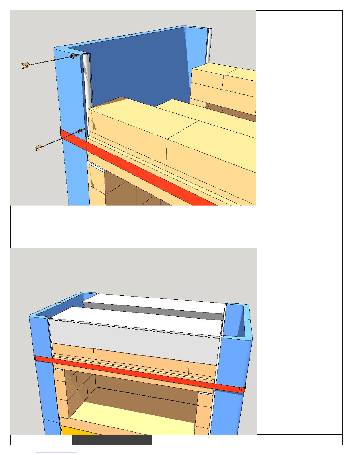
Measure the thickness
of your firebricks (for
example, 2-1/4",
2-5/16", etc.)
Measure from the top
arrow, down to 5" +
the thickness of your
firebrick. For example,
if your firebrick is 21/4", then you would
measure down 7-1/4".
Put a mark on the
channel at this height.
Repeat at the rear.
In order to come out at
the right height to the
top, a height
adjustment is required
here.
If you need more than 1-1/4" of adjustment, use firebrick splits.
Otherwise, slice firebricks.
If you only need 1/2" or less, you can use ordinary brick mortar.
For 1/4" or less, use refractory mortar or refractory mortar with sand added.
Install the precast
ceiling transition pieces
onto a refractory
mortar bed.
Try to come out
slightly higher than the
channels, between
1/16" and 1/4".
Page 26
HeatKit core assembly manual
November 21, 2017
25
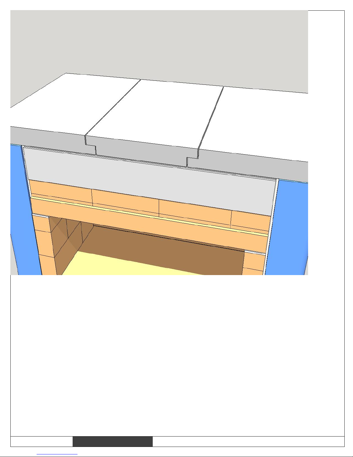
Install the precast ceiling slabs.
Use 2 people, and be careful with your staging, and plan your moves. The
pieces are heavy and need to be lifted above shoulder height.
Set the pieces dry onto the core.
Leave 1/8" gap at the joints.
Seal the pieces carefully with GE silicone (provided). Fill the joints including
the bottom.
Note a relief is cast into the top edge of the ceiling transition pieces, to
allow for a silicone joint. Go over the joints with a metal blade, brick tie,
etc. to force the silicone in and provide a permanent seal. If the joint
between the ceiling and the side channels is 1/4" or less, fill with silicone. If
larger, stuff with ceramic blanket (provided in a roll) first, and go over with
silicone.
Page 27
HeatKit core assembly manual
November 21, 2017
26
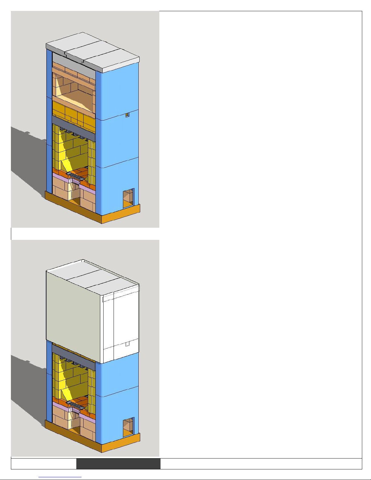
Seal the core at the fiberglass rope
side channel gaskets by applying a
bead of silicone where the gasket
touches the firebricks.
This takes care of any small gaps,
etc., that may be there. Silicone is
good to 500F and remains flexible,
and is suitable even for sealing
fairly large gaps if you have them.
Next step is to wrap the core with a
fiberglass matt slip joint. This
allows the core to slide up and
down inside the facing, when it
heats and cools.
Make sure not to accidentally
puncture the slip joint afterwards.
This could lead to direct contact
with the mortar slush used behind
the facing and defeat the purpose.
Fiberglass matt can be messy to
use. Plan your moves and handle it
carefully. Use 2 people.
Put small dabs of silicone on
approximately 6" centers where the
white area is in the graphic
Start with the shorter of the two
rolls.
With one person holding the end in
place, the second person unrolls
the fiberglass as they walk around
the heater. Keep the top 1" above
the core, and keep it flat and pat it
down against the fiberglass.
Overlap the ends about 4", and
trim off the excess length with
scissors or tin snips.
Use the metal tape provided to
secure the wrap (see next page)
Page 28
HeatKit core assembly manual
November 21, 2017
27
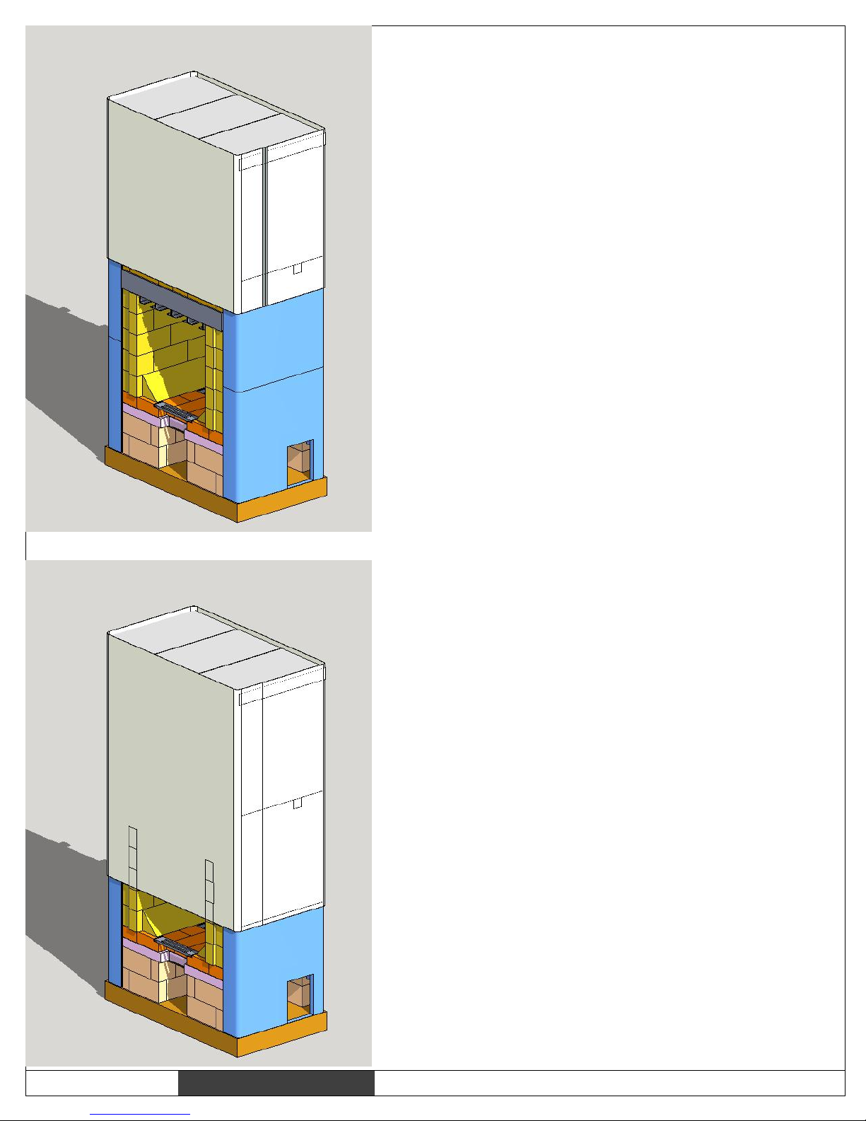
The metal tape is shown in place.
Repeat the process with the longer roll.
Page 29
HeatKit core assembly manual
November 21, 2017
28
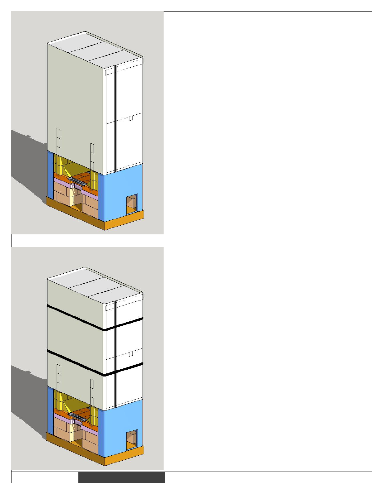
Metal tape in place on the longer
piece of wrap.
Most expansion happens in the upper
portion of the core, hence the
doubling up of the wrap near the top.
Vertical expansion is cumulative, and
there is almost none at the bottom.
Therefore, no wrap is required there,
and you can touch the core directly
with mortar slush.
Secure the wrap with two metal
straps as shown, or alternately
with concrete tie wire.
See next page for location of the
straps in relation to the openings.
Page 30
HeatKit core assembly manual
November 21, 2017
29
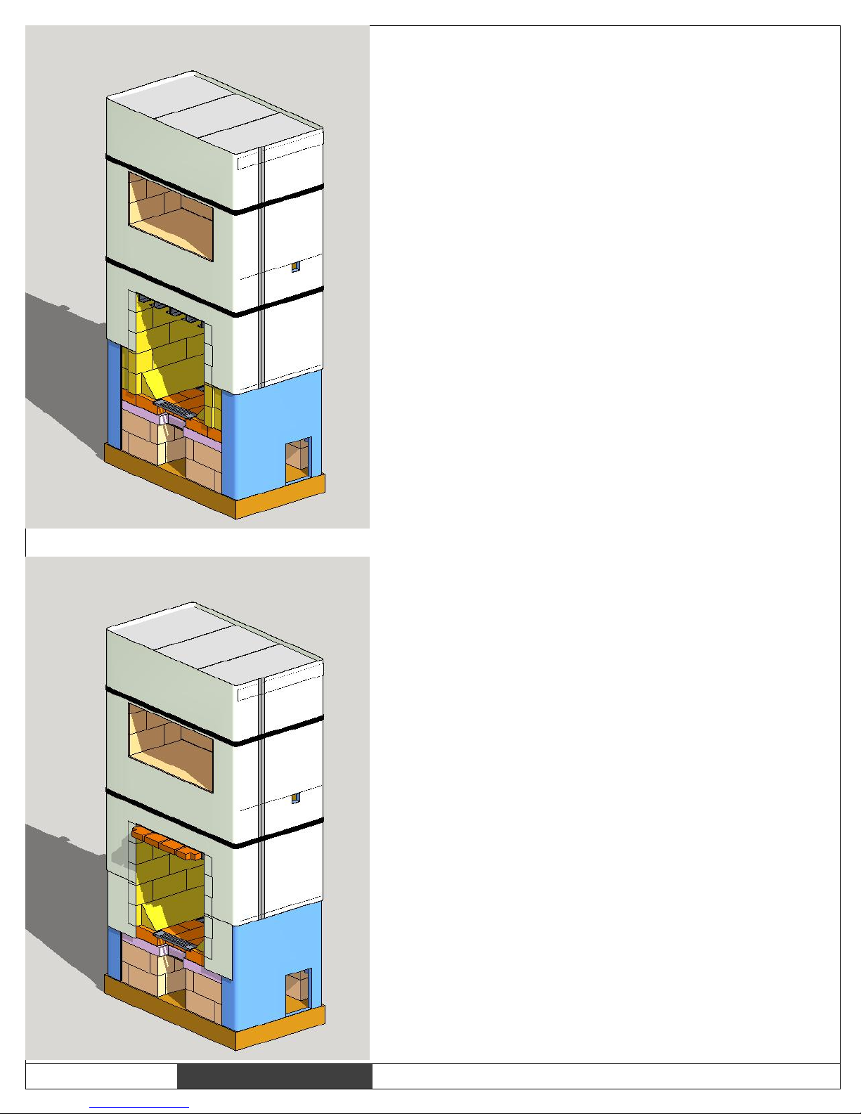
Using a utility knife with a fresh blade,
trim around the openings as shown.
Make sure to trim around the 2" x 2"
bypass opening also, which is easy to miss.
You will have a fuzzy edge with fibers
sticking out. Around the oven open, trim
these off using scissors.
From the cutoffs, cut two pieces
approx. 10" x 12", and use silicone
to glue them at the bottom of the
firebox front, as shown.
Page 31
HeatKit core assembly manual
November 21, 2017
30
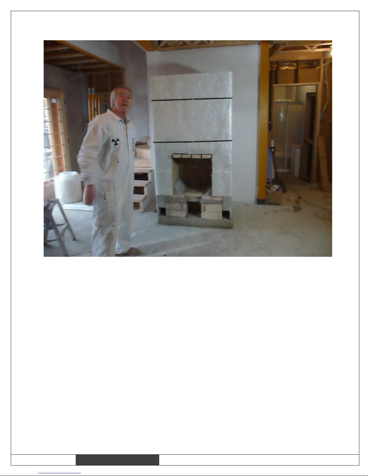
Heater core with fiberglass matt slip joint installed. Ready for facing.
This one does not have an oven.
 Loading...