

HEATIT Z-Smoke Detector Installation Manual
HEATIT
230V
ZSMOKE DETECTOR
01.03.2020
Ver 2020-A
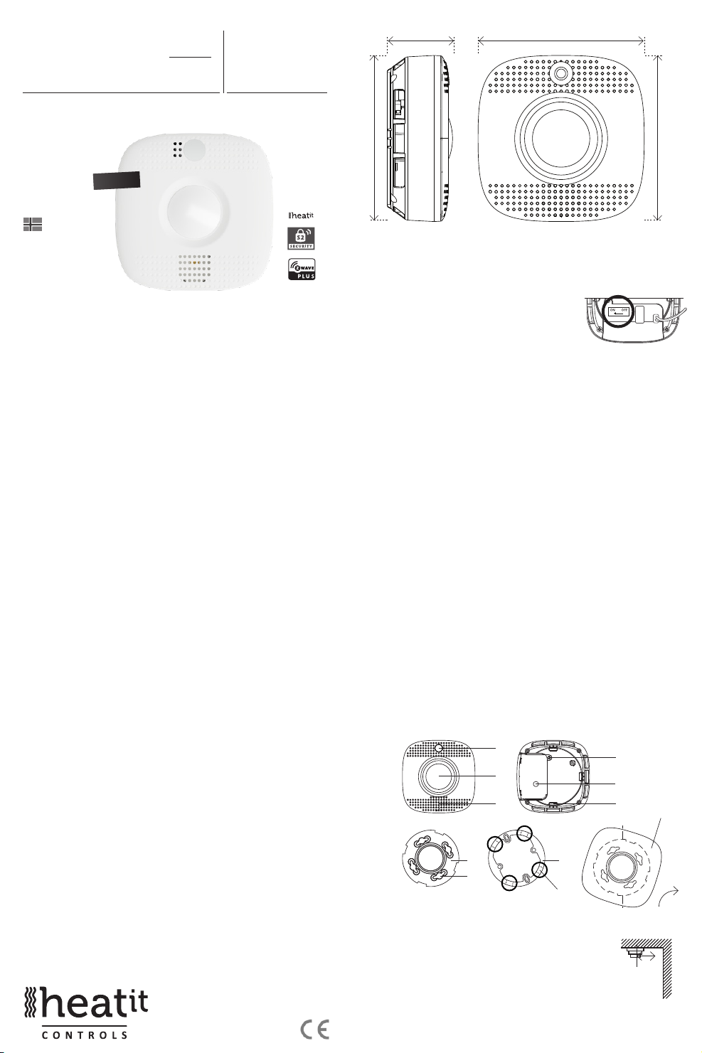
41,0 mm
10,5 mm
Installers manual
230V
Norwegian version
Download
manuals.thermo-oor.no
www.thermo-oor.no
TABLE OF CONTENTS
1. Introduction
2. Statement regarding products from multiple manufacturers
3. Quick Start
4. Installation/Mounting
5. Add/Remove
6. Behavior within the Z-Wave™ network
7. LED-indicator /Function button
8. Factory Reset
9. Testing the smoke detector
10. Alarm silence
11. Calibration
12. Serial connection
13. Security
14. Node Information Frame
15. Command Classes
15.1 Command Class Notication V8
15.2 Command Basic
15.3 Command Class Sensor Multilevel V11
15.4 Command Class Battery V1
16. Associations
16.1 Association Groups
Product information
1. INTRODUCTION
Heatit Z-Smoke Detector is a wireless smoke sensor with built-in PIR motion sensor,
temperature sensor and emergency light. Heatit Z-Smoke Detector is a wireless
operated photo-electronic smoke detector designed to interact with most Z-Wav e
enabled controllers. The detector features smoke-, temperature-, and IR-detection.
When other sensors in the Z-Wave network are activated and send an alarm signal,
the smoke detector will also sound an alarm with its built-in siren to help give
warning.
2. STATEMENT REGARDING PRODUCTS FROM MULTIPLE
MANUFACTURERS
Please read this before installation
This device may be used with all devices certied with the Z-Wave Plus™ certicate
and should be compatible with such devices produced by other manufacturers.
Every primary controller is dierent depending on the manufacturer, their
target audience and intended use/application. Please review the functionalities
implemented by the primary controller you intend to use with our Z-Wave Plus
certied device to ensure that it provides the necessary controls to take full
advantage of our product’s capabilities.
10,5 mm
10,5 mm
3. QUICK START
1. Unscrew the connection cover.
2. Connect the ”L” phase to one of the wago connectors on the back of the
smoke detector and connect the ”N” phase to the other wago connector.
3. Switch on the switch. Illustrated to the right.
4. The device will enter auto inclusion mode after
being powered on.
5. Set the primary controller in add mode
(security/non-security).
6. The Heatit Z-Smoke Detector is now included in your Z-Wave network.
4. INSTALLATION/MOUNTING
Installation must be done by a qualied electrician in accordance with the
National Building Codes. Before installation, disconnect any power to the smoke detector.
During installation of the smoke detector, power to the smoke detector must be
disconnected AT ALL TIMES!
Step 1. Place the smoke detector at the desired mounting location and use the Range
Test function to make sure the smoke detector can be detected by the control
panel where it has been placed.
Step 2. A mounting sheet is included in the package. The illustration size equals
the smoke detector’s actual size and the perforated design allows for easy
removal after installation.
Step 3. Position the sheet tightly against the wall/ceiling and use the four holes as a
template to drill holes and insert wall plugs in the wall/ceiling if so required.
Step 4. Place the mounting bracket on top of the mounting sheet and screw it onto
the wall/ceiling.
NB! If used with cable channels mount the adapter with bracket mounted on
the bottom.
Step 5. Connect Live and Neutral to the wago included in the packaging and place
the connections in grove disigned to ush mount the connections.
Step 6. The smoke detector has four notches on its back cover. Gently align the four
notches on the smoke detector with the hooks on the mounting bracket.
Rotate clockwise to lock the hook.
Step 7. Turn on the backup battery of device by turning the switch mounted inside
the device from OFF to ON.
Step 8. Installation is now complete. You may now tear o the mounting sheet.
Turn on fuse to provide power for the device.
a
b
c
g
h
a. LED-indicator/function button/emergency light
b. IR-lens
c. Buzzer
d. Connection compartment xing screw
e. Connection compartment
f. Hooks
g. Mounting bracket
h. Mounting holes (for the hooks on the mounting bracket)
i. Cable channel adapter
j. Mount by aligning notches and hooks, then rotate clockwise
i
Cable slots
dimensions 10x12mm
d
e
f
j
Lock
>60cm
At least 60 cm from
the wall
And turn on fuse to provide power for
Installation recommendations
• It is recommended to install the device in the center of
the ceiling.
• The device should be placed openly, unobstructed by
appliances and furniture.
• It is recommended to place a smoke detector at the
top of a stairway to detect heat and smoke rising from
below.
• For the device to function correctly, it is important to
ensure that its readings are done accurately in a stable
environment. In order to achieve this:
• Do not place the detector in the kitchen: Cooking fumes may trigger the
alarm.
• Do not place the detector near a ventilation fan, uorescent lamp or airconditioning unit: Air drafts may aect the accuracy of the detector.
• Do not place the detector near ceiling beams, at the top point of an “A” frame
type ceiling or over a cabinet: Stagnant air in these areas may aect the
accuracy of the detector.
• Do not place the detector where it may be exposed to direct sunlight.
• Avoid installing the smoke detector in areas where other installations may
cause rapid changes in temperature within the detection area, e.g. near air
conditioners, heaters, boilers or radiators.
• Avoid large obstacles in the detection area.
• Moving objects within the PIR detection area (e.g. curtains moving in a draft)
may cause an unwanted alarm. Avoid if possible.
To test the PIR motion sensor: Press the function button to enter test mode. Walk around
the protected area, and notice when the LED lights up. Check that the detection coverage
is adequate.
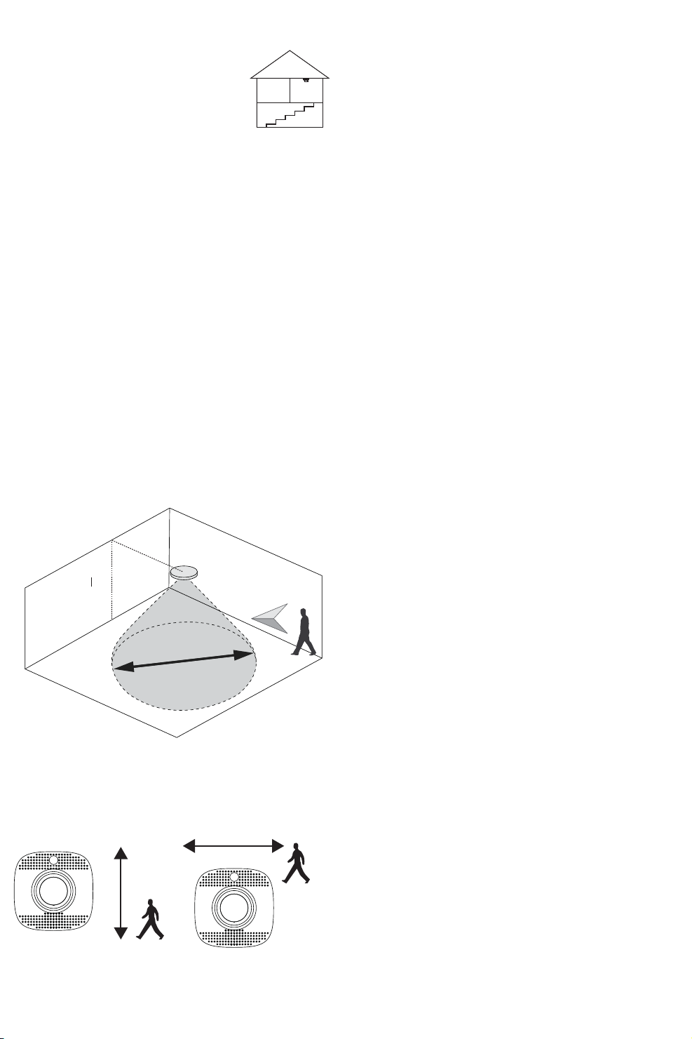
The smoke detector is designed to be mounted on the ceiling. The ideal mounting height
for the smoke detector is 2.7 to 3 meters above ground. Mounting the detector higher than
3 meters above ground may aect detection performance.
The smoke detector can support detection coverage within a radius of 4 meters. Please refer
to the illustrations below for installation details.
IR Detection Coverage
At the top of
a stairway
5. ADD/REMOVE
Please refer to your primary controller manual on how to enter add/remove mode.
The device may only be added or removed from the network if the primary controller
is in add/remove mode.
After power is applied, the smoke detector initiates a 1-minute warm-up period.
During this minute, the device will automatically enter add/remove mode, and
may now be added to the system via the primary controller.
After the calibration process is nished, you may access the add/remove mode by
pressing the function button three times within 1.5 seconds. Removing the device
will reset it to factory settings.
If the device already belongs to a network, you must remove it from that network before
adding into a new one, or the setup will fail. When the device is removed from the
network, it will revert to factory settings.
6. BEHAVIOR WITHIN THE ZWAVE NETWORK
This device may be operated within any Z-Wave network with Z-Wave-certied devices
from other manufacturers. All non-battery operated nodes within the network will act as
repeaters regardless of manufacturer to increase the reliability of the network. On delivery,
the device does not belong to any Z-Wave network. The device needs to be added to
an existing network to communicate with the other devices within it. Devices may also
be removed from a network. The add/remove processes are initiated by the primar y
controller/gaterway of the Z-Wave network.
The primary controller/gateway has a mode for adding or removing devices. Please refer
to your primary controller manual on how to set the primary controller in add/remove
mode. The device may only be added or removed from the network if the primary
controller/gateway is in add/remove mode.
7. LEDINDICATOR /FUNCTION BUTTON
Red LED
• Turns ON briey: Transmitting signal.
• Quick ash: Alarm.
• Flashes every second: Smoke detector in sleep mode, will not receive signals from
other smoke detectors. Check the connections.
• Flashes every 2 seconds: Smoke detector in warm-up and calibration process.
• Flashes every 4 seconds: Battery exhausted.
3m
2,7m
8m
When mounted on the ceiling, the PIR motion sensor can most easily detect horizontal
movement.
Not recommendedRecommended
Recommended
Orange LED
• Flashes every second: Device power-on/calibration failed.
• Flashes every 5 seconds: Detecting smoke failed or device malfunctioning.
• Flashes every 4 seconds: Battery exhausted.
• Flashes every 45 seconds: Low battery condition
Function button
• Press the button once to send a test signal and temperature report to gateway.
• Press the button once during an alarm to silence the alarm.
• Press the button 3 times within 1.5 seconds to send a learn code.
• Press and hold the button for 10 seconds to enter the calibration process.
• Press and hold the button for 20 seconds to perform a factory reset.
White LED (emergency light)
• The emergency light will begin to ash slowly to alert users that an alarm has
been triggered.
8. FACTORY RESET
Press and hold the function button for 20 seconds. This will reset the smoke detector. It
will also re-perform the calibration process.
NB! Please use this procedure only when the primary controller/gateway is missing or
otherwise inoperable.
9. TESTING THE SMOKE DETECTOR
By pressing the function button on the smoke detector, you can test if the smoke
detector is functioning normally.
• If the smoke detector functions normally, the Red LED turns on for 2 seconds,
followed by a 2-tone beep.
• If the buzzer sounds 2-tone beeps 3 times, the “Optical Chamber” on the smoke
detector is either dirty or out-of-order.
• If the buzzer sounds 2-tone beeps 5 times, the “Heat Sensor” is out of order.
 Loading...