

Page 1
HEATIT
55. 57 mm
71. 20 mm
55. 57 mm
71. 20 mm
Z-PUSH
BUTTON 8
Installers manual
IMPORTANT
PLEASE READ THIS BEFORE INSTALLATION
Press and hold down both keys together for 3s to be
added to or removed from Z-Wave network by Z-Wave
master (primary) controller.
Group 2:
Click to turn on,
Press and hold
down to increase
light intensity
Firmware 1.25
01.09.2018
Ver 2018-A
Group 2:
Click to turn
o, Press and
hold down to
decrease light
intensity
Group 3: Group 3:
Group 4: Group 4:
Group 5: Group 5:
SAFETY & WARNINGS
• This device contains a button lithium battery that shall be
stored and disposed properly.
• DO NOT expose the device to moisture.
QUICK START
• Step 1: Turn on your remote control.
• Step 2: Activate inclusion mode on your Z-Wave controller.
• Step 3: Activate inclusion mode of your remote control
by pressing and holding down both I and O of Group 2
together over 3 seconds.
PRODUCT DESCRIPTION
The remote control is a Z-Wave device that can both control
other Z-Wave devices and activate scenes in Gateways.
Although it is controlling other devices, the device cannot act
as Z-Wave network controller (primary or secondary) and will
always need a Z-Wave network controller to be added into a
Z-Wave network.
The remote control has following functions:
1. Control of groups of other Z-Wave devices using ON, OFF and
Dim commands.
2. Activation of scenes in Gateway mode.
The encryption modes that the remote control supports are S0,
S2 Authenticated and S2 Unauthenticated. When the remote
control is being included into a Z-Wave network, you can use
your primary controller/gateway to enable one encryption
mode or disable encryption. (The primary controller/gateway
shall support encryption mode configuration).
55. 57 mm
71. 20 mm
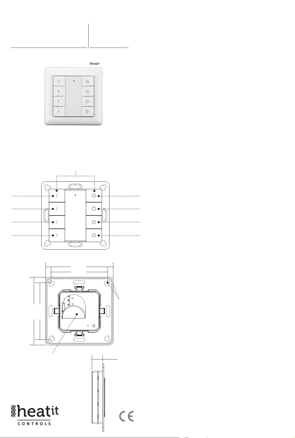
Battery: CR 2450
Before the rst use, please
remove the protective lm
Front side
71. 20 mm
55. 57 mm
Back side
14,6 m
The remote
control can be
xed on the
wall with 3M
glue or screw.
m
INSTALLATION GUIDE
Please read carefully the enclosed user manual before
installation of remote control, in order to ensure an error-free
functioning.
The remote control unit supplied as complete set for flush
mounting in the standard circular European wall boxes with
60mm diameter.
ADDING TO A Z-WAVE NETWORK
Step 1. Make sure the remote control does not belong to
any Z-Wave network, short press any button, if LED indicator
does not turn on, the remote control does not belong to any
network, then continue step 2, if LED indicator turns on, it
means the remote control has already been added to a network,
please first set the remote control to removing mode (refer to
the part ”Remowing” of this manual), then continue step 2.
Step 2. Set primary controller/gateway into adding mode
(Please refer to your primary controllers manual on how to turn
your controller into adding).
Step 3. Press and hold down both buttons I and O of Group 2
over 3 seconds, LED indicator turns on, the remote control will be
set to adding mode, and waiting to be added, after 10s LED
indicator blinks 6 times quickly to indicate successful adding.
Page 2
The remote control is a sleepy device, after adding it will
not enter into sleepy mode immediately, and will continue
activation status for 30s and wait data interaction from the
gateway, the LED indicator will stay solid on, please be patient
to wait LED indicator to turn off.
REMOVING FROM A Z-WAVE NETWORK
There are two removing methods:
Method 1: Removing from the primary controller/gateway as
follows:
1. Set the primary controller/gateway into removing mode
(Please refer to your primary controllers manual on how to set
your controller into removing).
2. Press and hold down both buttons I and O of Group 2 over
3 seconds, LED indicator turns on, the remote control will be
set to removing mode, and waiting to be removed, after 7s LED
indicator blinks 4 times quickly to indicate successful removing.
Method 2: Factory reset the remote control will force the
remote control to be removed from a network. (Please refer to
the part “Factory Reset” of this manual)
Note: Factory reset is not recommended for removing, please
use this procedure only if the primary controller/gateway is
missing or otherwise inoperable.
HOW TO CHECK WHETHER THE REMOTE CONTROL ALREADY
ADDED TO A NETWORK
Short press any button, if LED indicator does not turn on, the
remote control does not belong to any network, if LED indicator
turns on, it means the remote control has already been added
to a network.
If the remote control already belongs to a network, follow the
removing process before adding it in your network. Otherwise
adding of this device will fail.
FACTORY RESET
Press and hold down both buttons I and O of Group 2 together
for over 10 seconds, LED indicator turns on and then blinks 4
times quickly to indicate successful factory reset.
ASSOCIATION
Z-Wave devices control other Z-Wave devices. The relationship
between one device controlling another device is called
association. In order to control a different device, the controlling
device needs to maintain a list of devices that will receive
controlling commands. These lists are called association groups
and they are always related to certain events (e.g. button
pressed). In case the event happens all devices stored in the
respective association group will receive a common wireless
command.
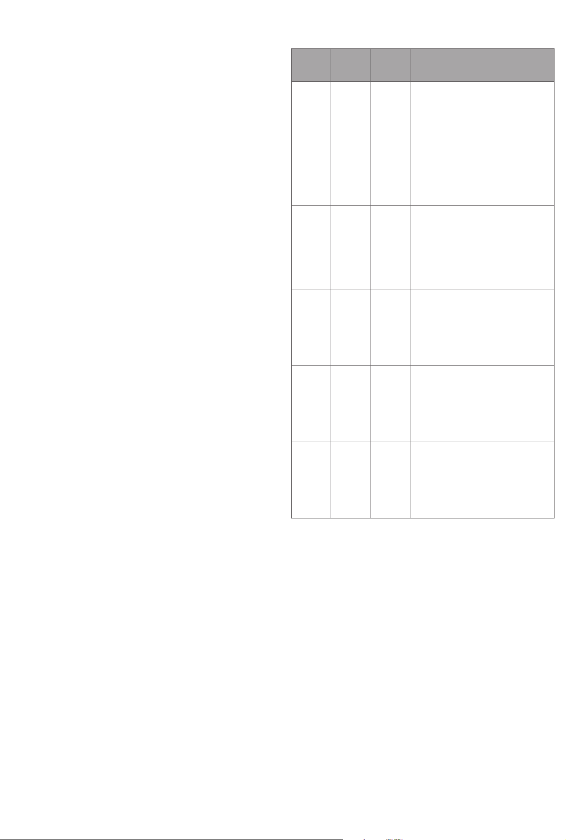
ASSOCIATION
GROUPS
Group 1 Lifeline. 5 1. Send Command Class ”Device Reset Lo-
Group 2 Launch 1 5 Short press I /O button of Group 2 to send
Group 3 Launch 2 5 Short press I /O button of Group 3 to send
Group 4 Launch 3 5 Short press I /O button of Group 4 to send
Group 5 Launch 4 5 Short press I /O button of Group 5 to send
GROUP
NAME
SET AND UNSET ASSOCIATIONS
NOTE: ALL ASSOCIATION INFORMATION WILL BE CLEARED
AUTOMATICALLY ONCE THE REMOTE CONTROL IS EXCLUDED FROM
A NETWORK.
MAX
NODES
DESCRIPTION
cally Notification V1” to associated devices of
this group to report factory reset information
when factory reset the remote control.
2. When remote control battery power value
changes, send Command Class ”Battery
Report V1” to associated devices of this group
to report power value information.
3. Short press or press and hold any button
to send scene activation command to the
associated devices of this group using
Command Class “Central Scene Notification
V3”
ON/OFF command to associated devices of
this group using Command Class
”Basic Set V2”.
Press and hold down I / O button of Group 2
to send light intensity
increase/decrease command to associated
devices of this group using Command Class
”Multilevel V4”.
ON/OFF command to associated devices
of this group using Command Class ”Basic
Set V2”.
Press and hold down I / O button of Group
3 to send light intensity increase/decrease
command to associated devices of this group
using Command Class ”Multilevel V4”.
ON/OFF command to associated devices
of this group using Command Class ”Basic
Set V2”.
Press and hold down I / O button of Group
4 to send light intensity increase/decrease
command to associated devices of this group
using Command Class ”Multilevel V4”.
ON/OFF command to associated devices
of this group using Command Class ”Basic
Set V2”.
Press and hold down I / O button of Group
5 to send light intensity increase/decrease
command to associated devices of this group
using Command Class ”Multilevel V4”.
There are two methods to set associations:
1. Set association by operating primary controller/gateway to
send association command to the remote control:
When set association from primary controller/gateway, the
remote control shall be activated first, if it is not activated, you
should activate it manually.
ASSOCIATION GROUPS
Each group supports maximum 5 nodes for association, the
same device can be associated with multiple groups on
the remote control simultaneously, to ensure better control
experience, the remote control shall remove the associated
devices that are not under working status from association
groups in time.
The primary controller/gateway sends association command
to the remote control using “Command Class ASSOCIATION” or
“Command Class Multi Channel Association”
2. Set association by operating the remote control and devices
to be controlled:
Page 3

To control a Z-Wave device from the remote control the node
ID of this device needs to be assigned to one of the two
association groups. This is a three-step process:
1. Press and hold down both buttons I and O of Group 2 over
3 seconds, LED indicator turns on.
2. Short press I button of any group within 7s to associate the
device to this group, short press O button of any group within
7s to remove association of the device from this group.
3. Operate the device to be controlled to send Node
Information Frame (please refer to the device manual) within 10
seconds, or set the device to exclusion mode within 10 seconds,
since it will send Node Information Frame in exclusion mode,
LED indications are as follows:
- LED blinks twice to indicate that the remote control failed to
add the associated device (the association group has already
added maximum quantity associated devices that it supports ).
- LED blinks 5 times to indicate that the remote control added
the associated device successfully.
- LED blinks 8 times to indicate that the remote control removed
the associated device successfully.
- Short press or press and hold down any button to send scene
activation command to association Group 1 using Command
Class ”Central Scene Notification V3”.
- Short press I / O button of Group 2, send ON/OFF command
to all associated devices of Association Group 2.
- Press and hold down I / O button of Group 2, send light
intensity increase/decrease command to all associated devices
of Association Group 2.
- Short press I / O button of Group 3, send ON/OFF command
to all associated devices of Association Group 3.
- Press and hold down I / O button of Group 3, send light
intensity increase/decrease command to all associated devices
of Association Group 3.
- Short press I / O button of Group 4, send ON/OFF command
to all associated devices of Association Group 4.
- Press and hold down I / O button of Group 4, send light
intensity increase/decrease command to all associated devices
of Association Group 4.
TO REMOVE ALL ASSOCIATED DEVICES IN AN ASSOCIATION
GROUP ON THE REMOTE CONTROL DIRECTLY:
1. Press and hold down both buttons I and O of Group 2 over 3
seconds, LED indicator turns on.
2. Click OFF button of any group on the remote control 5 times
continuously within 7 seconds to remove all associated devices
of this group, LED indicator blinks 8 times to indicate that the
associated devices are removed successfully.
OPERATING THE DEVICE
Press and hold down both keys together for 3s to be
added to or removed from Z-Wave network by Z-Wave
master (primary) controller.
Group 2:
Group 2:
Click to turn on,
Press and hold
down to increase
light intensity
Click to turn
o, Press and
hold down to
decrease light
intensity
- Short press I / O button of Group 5, send ON/OFF command
to all associated devices of Association Group 5.
- Press and hold down I / O button of Group 5, send light
intensity increase/decrease command to all associated devices
of Association Group 5.
How to communicate with the device
The remote control is under sleepy mode for most of the time to
save battery power. It can not receive wireless command under
sleepy mode. Before the gateway interacts data with the remote,
the remote control shall be activated manually first. Short press
any button to activate the remote control for 3s, and press and
hold down I and O buttons of Group 2 together over 1 second
to activate the remote control for 7s.
Node Information Frame
The Node Information Frame is the business card of a Z-Wave
device. It contains information about the device type and the
technical capabilities. The inclusion and exclusion of the device
Group 3: Group 3:
is confirmed by sending out a Node Information Frame. Beside
this it may be needed for certain network operations to send
Group 4: Group 4:
out a Node Information Frame.
Front side
Group 5: Group 5:
How to send out Node Information Frame:
Set the wall controller into adding/removing mode: Press and
hold down both I and O buttons of Group 2 over 3 seconds, LED
indicator turns on to indicate the wall controller has already sent
out Node Information Frame, the user can repeat the operation
to set the wall controller to quit “adding/removing mode”.
Ver 2017-A
Page 4

PRODUCT INFO Heatit Z-Push Button 8
•
Battery operated wall switch with 8 push buttons
•
Fits Gira System 55, Elko RS-16 and Schneider Exxact frames
•
Can control 5 association groups and up to 20 units
•
Can control 8 separate scenes
•
LED- Diode
•
Easy to install with screws and double-sided tape
•
Supports encryption mode: S0, S2 Authenticated Class,
S2 Unauthenticated Class
TECHNICAL DATA
Protocol Z-Wave, 868,4 MHz
SDK 6.71.01
Rated voltage 1 x CR 2450 battery
Push Button 8
Min/max installation temp.0 - 40°C
Relative humidity 8% - 80%
Nettwork range Up to 20 meters
(depending on surroundings)
IP Class IP 20
Size LxWxD 71,2 x 71,2 x 13,6mm
Explorer Frame Support Yes
Device Type Wall controller
Generic Device Class Switch Remote
Specic Device Class Switch Remote Multilevel
Routing No
Flirs No
Approvals CE
RoHS 2011/65/EU
COMMAND CLASSES
Supported Command Classes
• COMMAND_CLASS_ZWAVEPLUS_INFO_V2
• COMMAND_CLASS_ASSOCIATION_V2
• COMMAND_CLASS_MULTI_CHANNEL_ASSOCIATION_V3
• COMMAND_CLASS_CENTRAL_SCENE_V3
• COMMAND_CLASS_ASSOCIATION_GRP_INFO_V1
• COMMAND_CLASS_TRANSPORT_SERVICE_V2
• COMMAND_CLASS_VERSION_V2
• COMMAND_CLASS_MANUFACTURER_SPECIFIC_V2
• COMMAND_CLASS_DEVICE_RESET_LOCALLY_V1
• COMMAND_CLASS_POWERLEVEL_V1
• COMMAND_CLASS_BATTERY_V1
• COMMAND_CLASS_SECURITY_V1
• COMMAND_CLASS_SECURITY_2_V1
• COMMAND_CLASS_WAKE_UP_V2
• COMMAND_CLASS_SUPERVISION_V1
Controlled Command Classes
• COMMAND_CLASS_CENTRAL_SCENE_V3
• COMMAND_CLASS_BASIC_V2
• COMMAND_CLASS_SWITCH_MULTILEVEL_V4
• Multi Channel V3
• Security_V1
• Security_2_V1
WARRANTY
2 years
Heatit Controls AB can
not be held liable for
typographical errors, other
errors or omittances in
our information.
Product specifications
may change without
further notice.
All electrical installations
must be carried out by a
licensed electrician.
The product must be installed
in accordance with national
building codes and our
installers manual.
Heatit Controls AB l Läkarvägen 4, 454 31 BRASTAD, SWEDEN
Phone: +47 61 18 77 77 l post@heatit.com – www.heatit.com
 Loading...