

Heatit Z-PASH BUTTON 4 Installation Manual
HEATIT
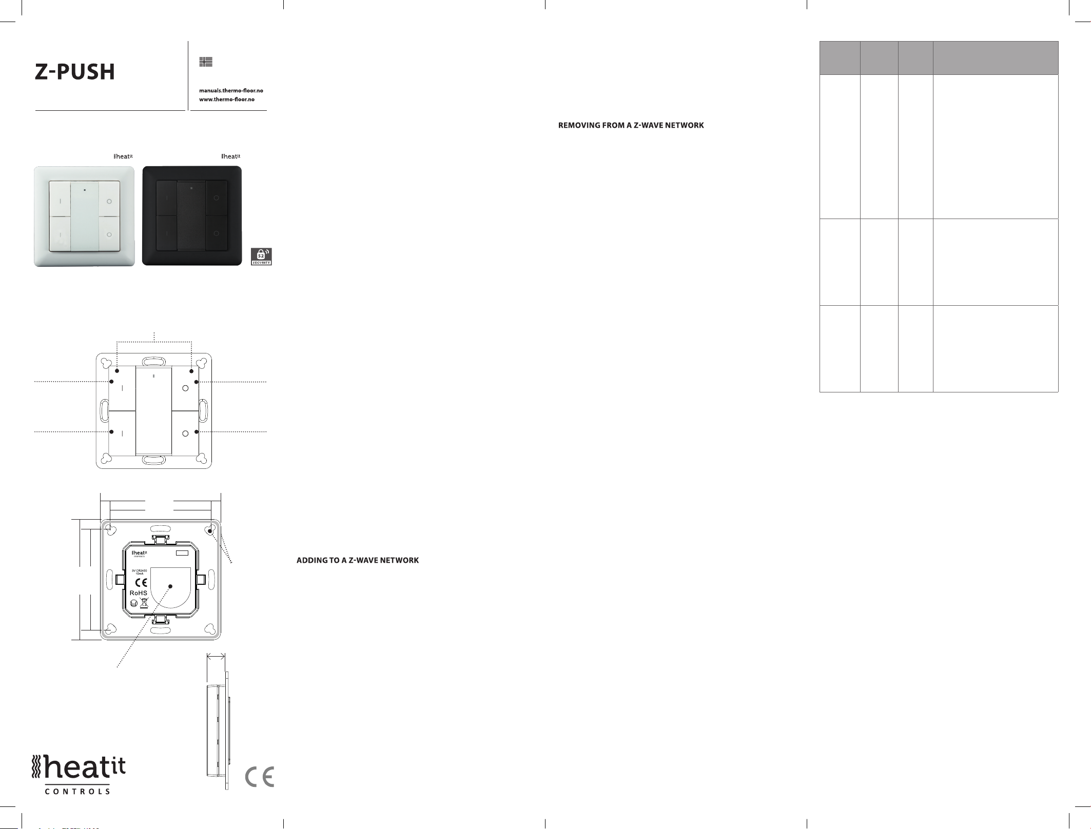
Heatit Z-Push Button 4 White
45 126 82
BUTTON 4
Installers manual
IMPORTANT
PLEASE READ THIS BEFORE INSTALLATION
Press and hold down both keys together for 3s to be
added to or removed from Z-Wave network by Z-Wave
master (primary) controller.
Group 2:
Click to turn on,
Press and hold
down to increase
light intensity
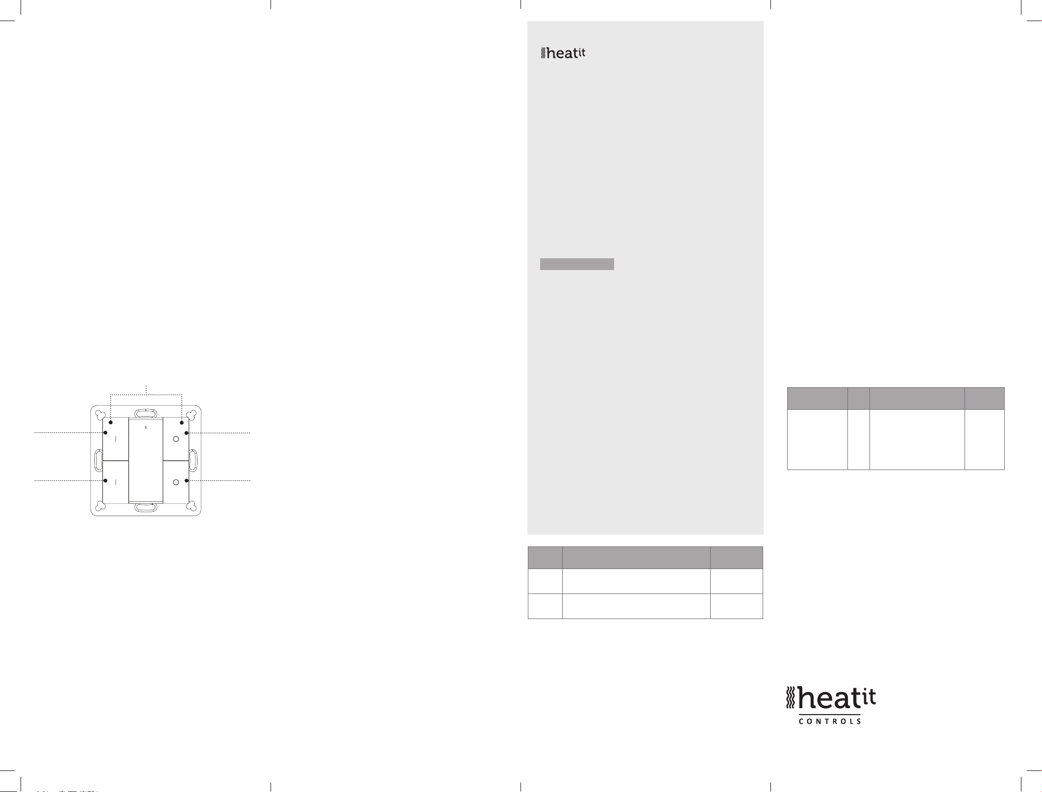
55. 57 mm
71. 20 mm
Battery: CR 2450
Before the first use, please
remove the protective film
Front side
71. 20 mm
55. 57 mm
Back side
TM
Norwegian version
Download
01.05.2019
Group 2:
Click to turn
o, Press and
hold down to
decrease light
intensity
The Push
Button can be
fixed on the
wall with 3M
glue or screw.
11mm
Ver 2019-A
Group 3: Group 3:
SAFETY & WARNINGS
• This device contains a button lithium battery that must be
stored and disposed of properly.
• DO NOT expose the device to moisture.
QUICK START
• Step 1: Turn on your Push Button.
• Step 2: Activate adding mode on your Z-Wave controller.
TM
• Step 3: Activate adding mode of your Push Button by pressing
and holding down both I and O of Group 2 for 3 seconds.
PRODUCT DESCRIPTION
The Heatit Push Button is a Z-Wave device that can both
control other Z-Wave devices and activate scenes in gateways.
Although it is controlling other devices, the Push Button cannot
act as Z-Wave network controller (primary or secondary) and
will always need a Z-Wave network controller to be added into a
Z-Wave network. It also supports the Over The Air (OTA) feature
for the products rmware upgrade.
This product can be operated in any Z-Wave network with other
Z-Wave certied devices from other manufacturers.
The Heatit Push Button has the following functions:
1. Control of groups of other Z-Wave devices using ON, OFF and
Dim commands.
2. Activation of scenes in Gateway mode.
The encryption modes that the Push Button supports are S0,
S2 Authenticated and S2 Unauthenticated. When the Push
Button is being added to a Z-Wave network, you can use your
primary controller/gateway to enable encryption mode or
disable encryption. (The primar
y controller/gateway must
support encryption mode conguration).
INSTALLATION GUIDE
Please read carefully the enclosed user manual before installing the
Push Button, in order to ensure error-free operation.
The Heait Push Button unit comes as a complete set for ush
mounting in standard European wall boxes with a 60mm diameter.
Step 1. Make sure the device does not belong to any Z-Wave
network by pressing any button once. If the LED indicator does
not turn on, the Push Button does not belong to any network,
and you may continue to step 2. If the LED indicator turns
on, it means that the Push Button has already been added
to a network. You must then run the removal process (see
”Removing from a Z-Wave network” in this guide) before moving
on to step 2.
Step 2. Set primary controller/gateway to adding mode (Please
refer to your primary controller manual on how to set your
controller to adding mode).
Step 3. Press and hold down both buttons I and O of Group 2
for 3 seconds. The LED indicator turns on, the Push Button will be
set to adding mode, and stand by to be added to the network.
After 10s the LED indicator blinks 6 times quickly to indicate that
the addition has been successful.
The Heatit Push Button is a sleeping device. After adding it to
the network, it will not enter into sleep mode immediately, but
will maintain activation status for 30s while completing the
addition process. The LED indicator will stay on for this time, so
please be patient and wait for the LED indicator to turn o.
There are two removing methods:
Method 1: Removing from the primary controller/gateway:
1. Set the primary controller/gateway to removing mode.
(Please refer to your primary controller manual on how to set
your controller to removing mode).
2. Press and hold down both buttons I and O of Group 2 for 3
seconds, LED indicator turns on, the Push Button will be set to
removing mode, and stand by to be removed. After 7s the LED
indicator blinks 4 times quickly to indicate successful removal.
Method 2: A factory reset of the Push Button will force the Push
Button to be removed from a network. (Please refer to the part
“Factory Reset” of this manual).
Note: Factory reset is not recommended for removing devices.
Please use this procedure only if the primary controller/gateway
is missing or otherwise inoperable.
HOW TO CHECK IF THE PUSH BUTTON HAS ALREADY BEEN
ADDED TO A NETWORK
Press any button once. If the LED indicator does not turn on,
the Push Button does not belong to any network. If the LED
indicator turns on, it means that the Push Button has already
been added to a network. You must then run the removal
process (see ”Removing from a Z-Wave network” in this guide)
before adding the device to your network.
FACTORY RESET
Press and hold down both buttons I and O of Group 2 for a
minimum of 10 seconds until the LED indicator turns on and
then blinks 4 times quickly to indicate successful factory reset.
Please use this procedure only when the network primary
controller is missing or otherwise inoperable.
ASSOCIATION
Z-Wave devices control other Z-Wave devices. The relationship
between one device controlling another device is called association.
In order to control a subordinate device, the controlling device
needs to maintain a list of devices that will receive controlling
commands. These lists are called ”Association Groups” and are
activated when specic events are registered (e.g. sensor reports).
In the case of an association group being triggered, all devices
stored in the respective association group will receive
a common wireless command.
ASSOCIATION GROUPS
Each group supports maximum 5 nodes for association. A single
device may be associated with multiple groups in the gateway
simultaneously. In order to optimize your control experience,
the gateway will automatically remove devices that are not in
operational status in their association groups at the time.
ASSO
CIATION
GROUPS
Group 1 Lifeline. 5 1. Send Command Class ”Device
Group 2 Launch 1 5 Push I-/O-button of Group 2 once
Group 3 Launch 2 5 Push I-/O-button of Group 3 onceto
SETTING AND REMOVING ASSOCIATIONS
(Note: All association information will be cleared automatically
once the device is excluded from the network.)
GROUP
NAME
MAX
NODES
DESCRIPTION
Reset Locally Notication V1” to
associated devices of this group to
report factory reset information when
factory reset the Push Button.
2. When Push Button battery power
value changes, send Command Class
”Battery Report V1” to associated
devices of this group to report power
value information.
3. Push once or press and hold any
button to send scene activation
command to the associated devices
of this group using Command Class
“Central Scene Notication V3”
to send ON/OFF command to
associated devices of this group using
Command Class ”Basic Set V2”.
Press and hold down I-/O-button of
Group 2 to send light intensity
increase/decrease command to
associated devices of this group using
Command Class ”Multilevel V4”.
send ON/OFF command to associated devices of this group using
Command Class ”Basic Set V2”.
Press and hold down I-/O-button
of Group 3 to send light intensity
increase/decrease command to
associated devices of this group using
Command Class ”Multilevel V4”.
There are two methods to set associations:
1. Set association by operating primary controller/gateway to
send the association command to the Push Button:
When setting association from the primary controller/gateway,
the Push Button must be activated rst. If it is not activated, you
should activate it manually.
The primary controller/gateway sends an association command
to the device using “Command Class ASSOCIATION” or
“Command Class Multi Channel Association”
2. Set association using the Push Button and the devices that
are to be controlled.
To control a Z-Wave device from the Push Button, the node ID of
this device needs to be assigned to one of the two association
groups. This is a three-step process:
a. Press and hold down both buttons I and O of Group 2 for
3 seconds until the LED indicator turns on.
b. Push the I-button of any group once within 7s to associate
the device to this group. Push the O-button of any group once
within 7s to remove association of the device from this group.
c. Send Node Information Frame (please refer to the device
manual) from the subordinate device within 10 seconds, or set
the device to removing mode within 10 seconds, since this will
send Node Information Frame in removing mode.
LED indications are as follows:
- LED blinks twice to indicate that the Push Button failed to add
the associated device (the association group has already added
the maximum quantity of associated devices that it is able to
support).
- LED blinks 5 times to indicate that the Push Button added the
associated device successfully.
- LED blinks 8 times to indicate that the Push Button removed
the associated device successfully.
TO REMOVE ALL ASSOCIATED DEVICES IN AN ASSOCIATION
GROUP IN THE PUSH BUTTON DIRECTLY:
1. Press and hold down both buttons I and O of Group 2 over 3
seconds, LED indicator turns on.
2. Click OFF button of any group on the Push Button 5 times
continuously within 7 seconds to remove all associated devices
of this group, LED indicator blinks 8 times to indicate that the
associated devices are removed successfully.
OPERATING THE DEVICE
Press and hold down both keys together for 3s to be
added to or removed from Z-Wave network by Z-Wave
master (primary) controller.
Group 2:
Click to turn on,
Press and hold
down to increase
light intensity
Front side
Group 2:
Click to turn
o, Press and
hold down to
decrease light
intensity
Group 3: Group 3:
- Push I-/O-button of Group 2 once, to send ON/OFF command
to all associated devices of Association Group 2.
- Press and hold down I-/O-button of Group 2, to send light
intensity increase/decrease command to all associated devices
of Association Group 2.
- Push I-/O-button of Group 3 once, to send ON/OFF command
to all associated devices of Association Group 3.
- Press and hold down I-/O-button of Group 3, to send light
intensity increase/decrease command to all associated devices
of Association Group 3.
- Push any button once or press and hold down any button to
send scene activation command to association Group 1 using
Command Class ”Central Scene Notication V3”.
How to communicate with the device
The Heatit Push Button is in sleep mode most of the time to
save battery power. It can not receive wireless commands when
in sleep mode. Before the gateway may interact with the Push
Button, the device must be activated manually rst. Push any
button once to activate the Push Button for 3s, and press and
hold down both the I- and O-buttons of Group 2 for 1 second to
activate the Push Button for 7s.
Node Information Frame
The Node Information Frame is the business card of a Z-Wave
device. It contains information about the device type and the
technical capabilities. The add and remove procedure of the device i
conrmed by sending out a Node Information Frame. Besides this, it
may be necessary for certain network operations to send out a Node
Information Frame.
How to send out Node Information Frame:
Set the Push Button to adding/removing mode: Press and hold
down both I- and O-buttons of Group 2 for 3 seconds. The LED
indicator turns on to indicate that the Push Button has already
sent out a Node Information Frame. The user may repeat the
operation to turn the adding/removing mode o.
PRODUCT INFO Heatit Z-Push Button 4
•
Battery operated wall switch with 4 push buttons
•
Fits Gira System 55, Elko RS-16 and Schneider
Exxact frames
•
Controls 2 separate groups and up to 10 units
•
Controls up to 8 scenarios via your gateway
•
s
LED- Diode
•
Firmware update (OTA)
•
Easy to install with screws and double-sided tape
•
Supports encryption mode: S0, S2 Authenticated Class,
S2 Unauthenticated Class
TECHNICAL DATA
Protocol Z-Wave, 868,4MHz
SDK 6.71.01
Chip Z-Wave 500 chip
Rated voltage 1 x CR 2450 battery
Push Button 4
Min/max install. temp. 0 - 40°C
Relative humidity 8% - 80%
Nettwork range Up to 20 meters indoors
IP Class IP 20
Size LxWxD 71,2 x 71,2 x 13,6 mm
Explorer Frame Support Yes
Device Type Wall controller
Generic Device Class Switch Remote
Specific Device Class Switch Remote Multilevel
Routing No
Flirs No
Approvals CE
ART.
NO.
45 126 82 Heatit Z-Push Button 4 -
45 126 83 Heatit Z-Push Button 4 -
PRODUCT Z-WAVE
battery operated wall switch White
battery operated wall switch Black
(depending on surroundings)
RoHS 2011/65/EU
FREQUENCY
EU 868,4MHz
EU 868,4MHz
COMMAND CLASSES
Supported Command Classes
• COMMAND_CLASS_ZWAVEPLUS_INFO_V2
• COMMAND_CLASS_ASSOCIATION_V2
• COMMAND_CLASS_MULTI_CHANNEL_ASSOCIATION_V3
• COMMAND_CLASS_CENTRAL_SCENE_V3
• COMMAND_CLASS_ASSOCIATION_GRP_INFO_V1
• COMMAND_CLASS_TRANSPORT_SERVICE_V2
• COMMAND_CLASS_VERSION_V2
• COMMAND_CLASS_MANUFACTURER_SPECIFIC_V2
• COMMAND_CLASS_DEVICE RESET_LOCALLY_V1
• COMMAND_CLASS_FIRMWARE_UPDATE_MD_V4
• COMMAND_CLASS_POWERLEVEL_V1
• COMMAND_CLASS_BATTERY_V1
• COMMAND_CLASS_SECURITY_V1
• COMMAND_CLASS_SECURITY_2_V1
• COMMAND_CLASS_WAKE_UP_V2
• COMMAND_CLASS_SUPERVISION_V1
Controlled Command Classes
• COMMAND_CLASS_CENTRAL_SCENE_V3
• COMMAND_CLASS_BASIC_V2
• COMMAND_CLASS_SWITCH_MULTILEVEL_V4
• Multi Channel V3
• Security_V1
• Security_2_V1
Conguration Command Class
Parameter
HEX (DEC)
0x01(1) Only write
in parameter, no
report feedback
when get the
parameter)
Heatit Controls AB l Läkarvägen 4, 454 31 BRASTAD, SWEDEN
Phone: +47 61 18 77 77 l post@heatit.com – www.heatit.com
Size Description Default
1. Value=0x55AA, other values
2
are invalid, factory reset the
wall controller
typograp hical errors, other
The product must be installed
in acco rdance with national
Value
- -
Heatit Con trols AB can
not be held liable for
errors or omittances in
our inform ation.
Product specicatio ns
may change without
fu
rther notic e.
All electr ical installations
must be carried out b y a
licensed ele ctrician.
building codes and our
installers manual.
 Loading...