

Heatilator WS18-AU, WS22-AU Installation Instructions Manual
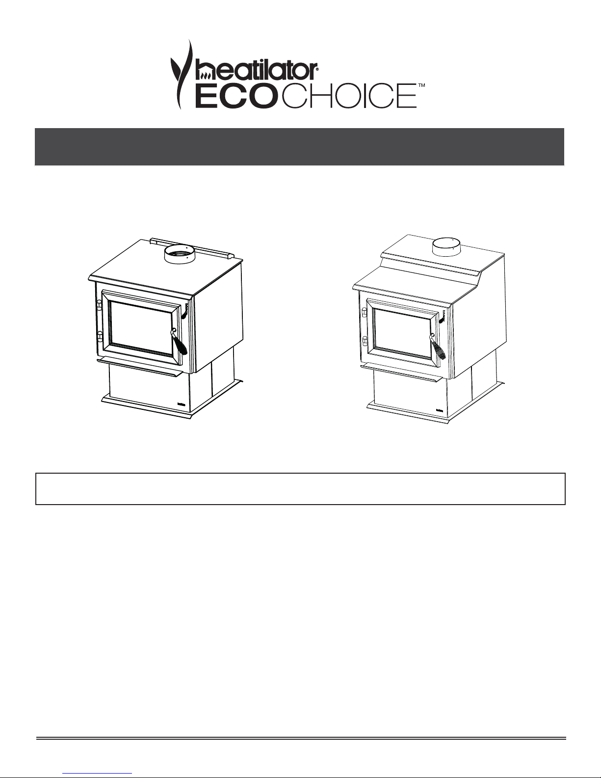
Eco-Choice WS Series Wood Burner Installation Instructions
Eco-Choice WS Series Wood Burner Installation Instructions
Model:
WS18-AU
INSTALLATIONS TO COMPLY WITH AS/NZS2918:2001
AND WILL REQUIRE A BUILDING CONSENT
Model:
WS22-AU
IMPORTANT: Read all instructions carefully before starting installation. Failure to follow these
instructions may result in a fi re hazard and will void the warranty.
• Fig. 3,4,5,6, 7 and Table 1,2,3,4 relate to installations with tested fl ue systems; as per AS/NZS
2918:2001 - Appendix F, with a ceiling angle between 0° - 30° inclusive.
• For installations with a ceiling angle greater than 30°, refer to Fig. 7 & 8 and AS/NZS 2918:2001
4.6.3(b)
• Ceiling Plate may vary in size depending on ceiling angle. Please specify ceiling pitch prior to
ordering the ceiling plate.
• Heatilator Eco Choice series wood burner’s are tested and approved to the N.Z. National Environ-
mental Standards;
WS18-AU Eco-Choice Hardwood Certifi ed
Particulate Emissions = 1.3 g/kg Space Heating Effi ciency = 85%
WS18-AU Eco-Choice Softwood Certifi ed
Particulate Emissions = 1.1 g/kg Space Heating Effi ciency = 73%
WS22-AU Eco-Choice Hardwood Certifi ed
Particulate Emissions = 1.2 g/kg Space Heating Effi ciency = 82%
WS22-AU Eco-Choice Softwood Certifi ed
Particulate Emissions = 1.3 g/kg Space Heating Effi ciency = 66%
Page 1
7056-153C
September 14, 2015
WS Series Wood Burner
Hearth & Home Technologies welcomes you to our tradition of excellence! In choosing a Heatilator appliance, you
have our assurance of commitment to quality, durability, and
performance.
This commitment begins with our research of the market,
including ‘Voice of the Customer’ contacts, ensuring we
make products that will satisfy your needs. Our Research
and Development facility then employs the world’s most
advanced technology to achieve the optimum operation of
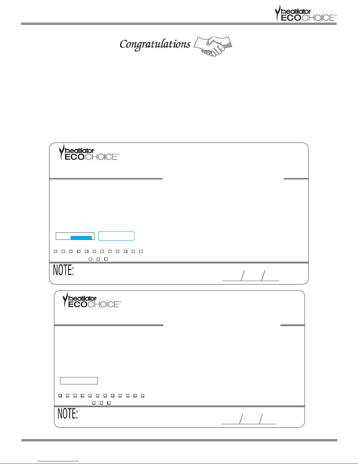
ECO CHOICE WOODFIRE COMPLIANCE LABEL
This appliance has been TESTED TO AS/NZS4013 for Softwood by HRL Technology Report # HCMG/14/027 Date tested: May 2014
This appliance has been TESTED TO AS/NZS4013 for Hardwood by HRL Technology Report # HCMG/14/004 Date tested: February 2014
OVERALL AVERAGE EFFICIENCY
AVERAGE PARTICULATE EMISSION FACTOR
MAXIMUM AVERAGE HEAT OUTPUT
SERIAL NO.
room for .14 x .875” S/N
007065
JAN FEB MAR APR MAY JUN JUL AUG SEP OCT NOV DEC
2014
2015 2016
1.5” x .375 Barcode Label
WETBACK - ALL MODELS
MODEL ECO CHOICE WS18 WOOD STOVE
TESTED TO AS/NZS 4012
TESTED TO AS/NZS 4013
APPROVED FUEL
MANUFACTURED BY
our stoves, inserts and fi replaces. And yet we are old-fash-
ioned when it comes to craftsmanship. Each unit is meticulously fabricated and surfaces are hand-fi nished for lasting
beauty and enjoyment. Our pledge to quality is completed
as each model undergoes a quality control inspection.
We wish you and your family many years of enjoyment in
the warmth and comfort of your hearth appliance. Thank
you for choosing Heatilator.
SOFTWOOD
73%
1.1 g/kg
7.5 kW
HARDWOOD
85%
1.3 g/kg
7.2 kW
BURN ONLY WOOD WITH A MOISTURE CONTENT LESS THEN 25% (dry
basis).
Wetbacks are NOT an approved option and must not be tted.
Hearth & Home Technologies, 1445 North Highway, Colville, WA
99114, United States of America.
PERFORMANCE MAY VARY FROM TEST VALUES DEPENDING ON ACTUAL
OPERATING CONDITIONS.
U.S. ENVIRONMENTAL PROTECTION AGENCY
Export stove. May not be operated within the United States.
INSTALLATION
DATE
7056-152
ECO CHOICE WOODFIRE COMPLIANCE LABEL
This appliance has been TESTED TO AS/NZS4013 for Softwood by HRL Technology Report # HCMG/14/029 Date tested: May 2014
This appliance has been TESTED TO AS/NZS4013 for Hardwood by HRL Technology Report # HCMG/14/006 Date tested: February 2014
OVERALL AVERAGE EFFICIENCY
AVERAGE PARTICULATE EMISSION FACTOR
MAXIMUM AVERAGE HEAT OUTPUT
SERIAL NO.
007066
JAN FEB MAR APR MAY JUN JUL AUG SEP OCT NOV DEC
2014
2015 2016
PERFORMANCE MAY VARY FROM TEST VALUES DEPENDING ON ACTUAL
OPERATING CONDITIONS.
U.S. ENVIRONMENTAL PROTECTION AGENCY
Export stove. May not be operated within the United States.
WETBACK - ALL MODELS
MODEL ECO CHOICE WS22 WOOD STOVE
SOFTWOOD
TESTED TO AS/NZS 4012
TESTED TO AS/NZS 4013
APPROVED FUEL
MANUFACTURED BY
BURN ONLY WOOD WITH A MOISTURE CONTENT LESS THEN 25% (dry
basis).
Wetbacks are NOT an approved option and must not be tted.
Hearth & Home Technologies, 1445 North Highway, Colville, WA
99114, United States of America.
66%
1.3 g/kg
8.1 kW
INSTALLATION
DATE
HARDWOOD
82%
1.2g/kg
9.4 kW
7057-139
Page 2
7056-153C
September 14, 2015
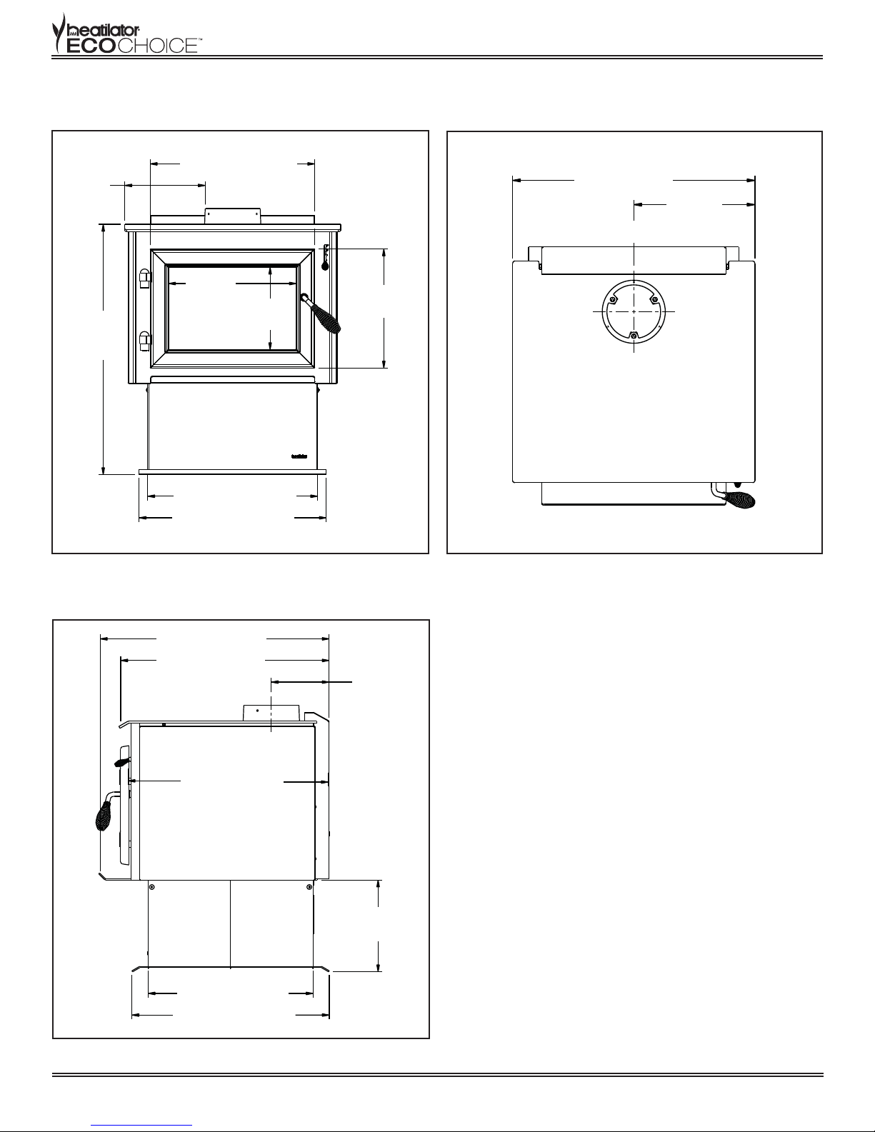
Heatilator WS18 Wood Burner Dimensions
19-1/16 in. (484 mm)
9-5/16 in.
(236 mm)
14-13/16 in.
29 in.
(736 mm)
(376 mm)
9-9/16 in.
(242 mm)
13-13/16 in.
(350 mm)
WS Series Wood Burner
25 in. (635mm)
C
L
12-1/2 in.
(317mm)
19-11/16 in. (500 mm)
21-11/16 in. (550 mm)
Figure 3.1 - Front View
26-1/2 in. (673mm)
24-1/8 in. (612mm)
23-1/4 in. (591mm)
Figure 3.2 -Top View
6-11/16 in.
(169mm)
C
L
19-1/16 in. (484mm)
22-13/16 in. (579mm)
Figure 3.3 - Side View
September 14, 2015
10-5/8 in.
(269mm)
7056-153C
Page 3

WS Series Wood Burner
FLOOR PROTECTOR
Heatilator WS18 does not require a insulating Floor Protector, as they are tested and comply with the
minimum Floor Protector requirements of AS/NZS 2918:2001.
Note:
▪ The minimum Floor Protector sizes are specifi ed in the clearance chart, see Table 1 & 2.
▪ A Floor Protector can include ceramic tiles with grouted joints fi xed directly onto a wooden fl oor or
a sheet of toughened glass, panel steel or any other non combustible material laid directly onto a
wooden fl oor.
▪ If installed directly onto a concrete slab, the concrete slab can be considered as the fl oor
protector,but must maintain the minimum measurement listed.
PARALLEL POSITIONING
Fig. 4
REAR WALL
G
SIDE WALL
Table 1
E
F
FLOOR PROTECTOR
D
C
DESCRIPTION Default Flue Kit
A Min. Clearance from back of unit to rear wall 175
B Min. clearance from center of spigot to rear wall 345
C Min. distance from front of base to fl oor protector front 300
D Min. fl oor protector front width 800
E Min. distance from rear wall to front of fl oor protector 1055
F Min. distance from unit side to side wall 300
G Min. clearance from center of spigot to side wall 618
B
A
REAR WALL
NOTE: HEAT SHIELD REQUIREMENTS FOR HEAT SENSITIVE WALLS
Clearances may be reduced by provision of an appropriately located heat shield refer to
AS/NZS 2198:2001 3.2.3 TABLE 3.1
Page 4
7056-153C
September 14, 2015
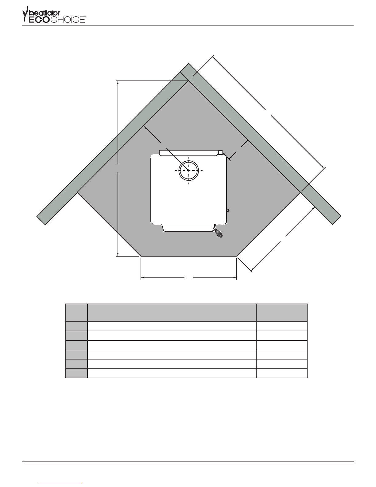
CORNER POSITIONING (45°)
Fig. 5
WS Series Wood Burner
F
CORNER WALL
B
FLOOR PROTECTOR
E
CORNER WALL
A
C
D
Table 2
DESCRIPTION Default Flue Kit
A Min. clearance from fi rebox corner to corner walls 155
B Min. distance from center of spigot to corner walls 470
C Min. distance from corner wall to fl oor protector front 1219
D Min. fl oor protector projection from corner wall 730
E Min. fl oor protector front width 692
F Min. overall fl oor protector depth 1379
FIREBOX INSTALLATION
1. If a separate fl oor protector is being used position now. Place the fi rebox on the fl oor protector to
suit the minimum installation clearances. (See Fig 3 or 4).
2. Seismically restrain the fi rebox and the fl oor protector to the fl oor.
3. Fit 2 x 6mm fi xings suitable for the fl oor material. DO NOT over tighten.
4. Fit timber trim pedestal edging to front and back of base (optional).
September 14, 2015
7056-153C
Page 5
 Loading...