

Heatilator ST-CFL-24NG, ST-CFL-24LP Log Placement Instructions
LOG PLACEMENT INSTRUCTIONS
Model:
NOTE: Following the instructions given below is very important (Flat spots will guide
you throughout the process). Use the log
numbers to identify your logs. Check to
make sure the tabs on the side of the burner
legs are bent outward. Af ter setting the burner, set the identical log grates one on each
side of the burner. Set them down and slide
each one toward burner . Make sure right and
left grate bars slide on outside of the burner
legs. Push the grate toward burner. Place
“dime size” pieces of mineral wool on top of
burner, spaced dimes width apart. For log
placement place each log standing at the
correct side of burner. Please refer to the
side desired prior to each log setting.
ST-CFL-24NG/LP
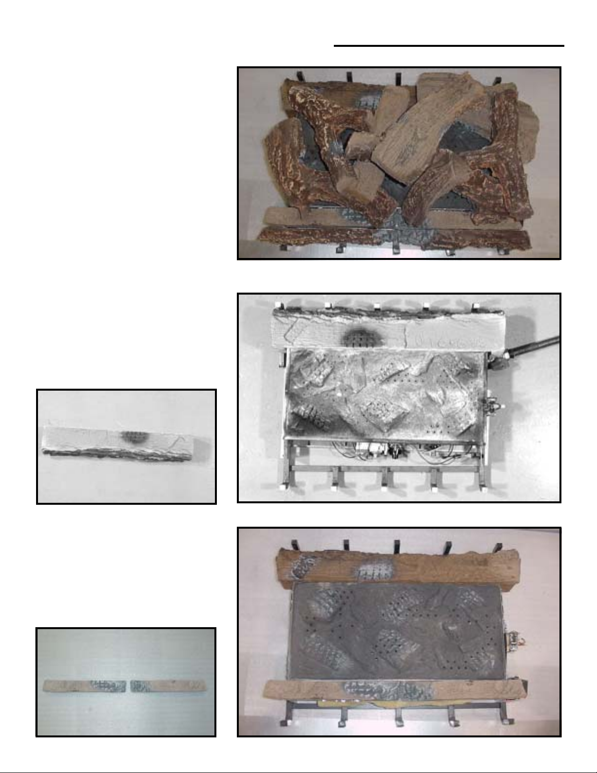
LOG #1: (SRV569-710)
Standing at the side opposite the valve, set
log #1 in front of the burner, between the
burner and the grate with the bark detail
facing away from the burner. Push the grate
along with the log to come in contact with
the burner.
1
1
LOG #2 & #3: (SRV569-71 1)
St anding at the valve side, set log #2 and #3
on the other side of the burner. Rest the
bottom two notches over extended material
of the burner leg. Push the log until it comes
in contact with the burner .
2
3
2
3
1
569-925D 4/04
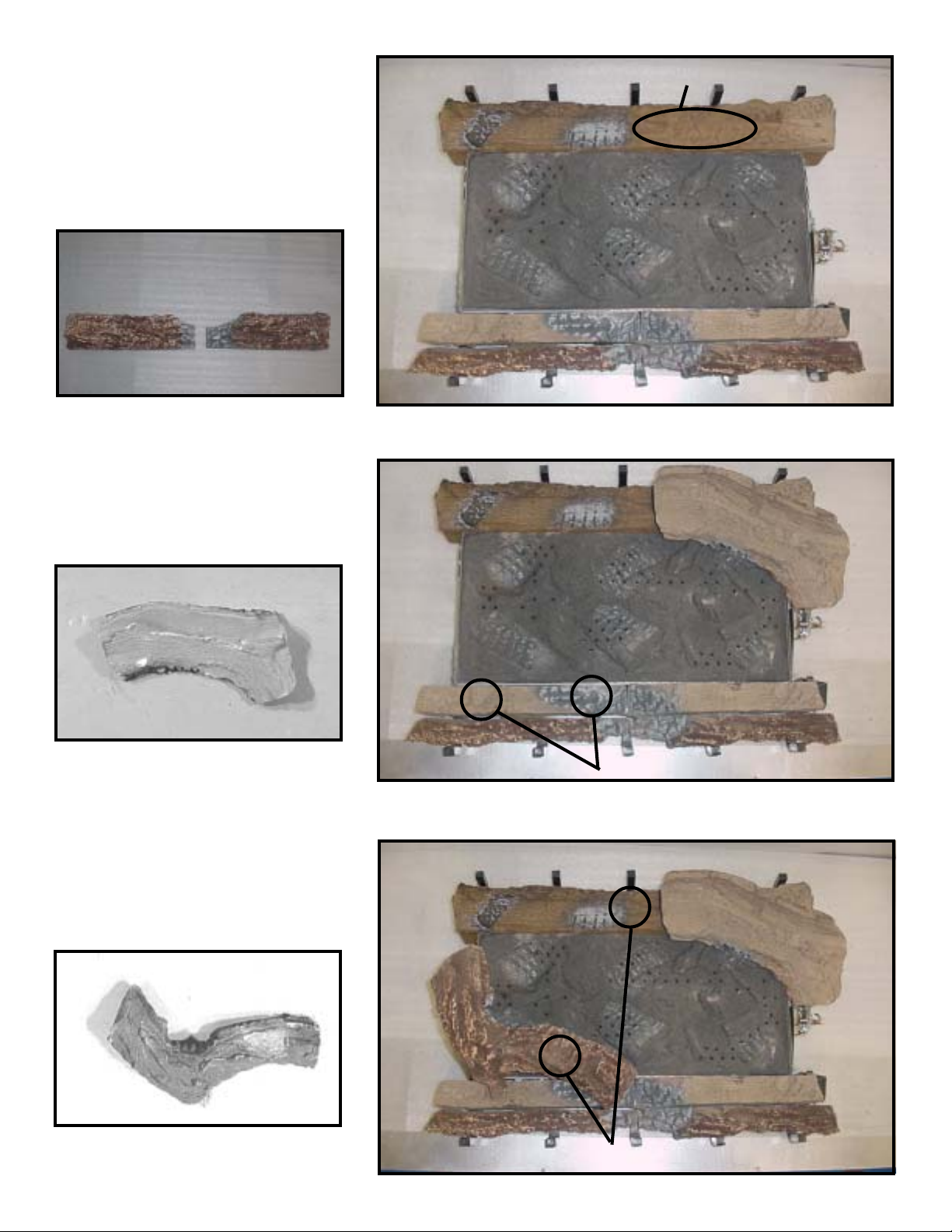
LOG #4 & #5: (SRV481-755)
Standing at the valve side, set logs #4 and
5 between the grate and logs #2 and 3 with
the bark detail towards the outside. Logs
#4 and 5 should be even with logs #2 and 3
from one side to the other. Slide gate to
hold in place.
FLAT SPOT (For log #6)
4
LOG #6: (SRV569-708)
Standing at the side opposite of the valve,
set log #6 on the top of log # 1 and the burner
to the left by following the flat spot pattern.
5
6
4
5
6
LOG #7: (SRV569-709)
St anding at the valve side, set log #7 on the
top of log #2 and the burner to the left by
following the flat spots pattern.
7
FLAT SPOTS (For log #7)
7
FLAT SPOTS (For log #8)
2
 Loading...