

Heatilator SIM-3630, SIM-3933, SIM-4236, SIM-4842 Installation Instructions Manual
SIM-3630, SIM-3933, SIM-4236, SIM-4842
Installation Instructions
Leave this manual with party responsible for use
and operation.
CAUTION! Risk of Cuts, Abrasions or Flying Debris.
Wear protective gloves and safety glasses during installation. Sheet metal edges are sharp.
DANGER
HOT GLASS WILL
CAUSE BURNS.
DO NOT TOUCH GLASS
UNTIL COOLED.
NEVER ALLOW CHILDREN
TO TOUCH GLASS.
A barrier designed to reduce the risk of
burns from the hot viewing glass is provided
with this appliance and shall be installed for
the protection of children and other at-risk
individuals.
WARNING! Risk of Fire! Combustible materials MUST
NOT overlap or be placed under a surround.
TOOLS REQUIRED:
• 1/4 inch drill driver with 1/4 hex bit
Proceed to “Install Hood.”
For the models listed below, it will be necessary to
remove the lower magnet latches and replace with a
shoulder screw:
NDV3630I,NDV3630IL,NDV3933I,NDV3933IL,
NDV4236I, NDV4236IL, NDV4842I, NDV4842IL
NBV3630I, NBV3933I, NBV4236I, NBV4842I
NNXT3933IF, NNXT3933ILF, NNXT4236IF,
NNXT4236ILF
TOOLS REQUIRED:
• 1/4 inch drill driver with #2 Phillips bit and 1/4 hex bit
CONTENTS:
• Decorative Front Assembly
• Hood
PREPARATION:
• Verify and remove contents from packaging before beginning installation.
• Refer to cleaning instructions on page 3.
CAUTION! Do not install damaged components.
WARNING! Risk of Fire! DO NOT apply combustible ma-
terials beyond the minimum clearances. Comply with all
minimum clearances to combustibles as specied. Overlapping materials could ignite and will interfere with proper
operation of doors and louvers.
For Models:
NDV3630I-B, NDV3630IL-B, NDV3933I-B,
NDV3933IL-B, NDV4236I-B, NDV4236IL-B,
NDV4236I-NVR, NDV4842I-B, NDV4842IL-B
NBV3630I-B, NBV3933I-B, NBV4236I-B, NBV4842I-B
NNXT3933IF-B, NNXT3933ILF-B, NNXT4236IF-B,
NNXT4236ILF-B
CONTENTS:
• Decorative Front Assembly
• Shoulder Screws (2)
• Installation Instructions
PREPARATION:
• Verify and remove contents from packaging before beginning installation.
• Refer to cleaning instructions on page 3.
Heatilator • SIM-3630, SIM-3933, SIM-4236, SIM-4842 Decorative Front Instructions • 2382-930 Rev. B • 9/17
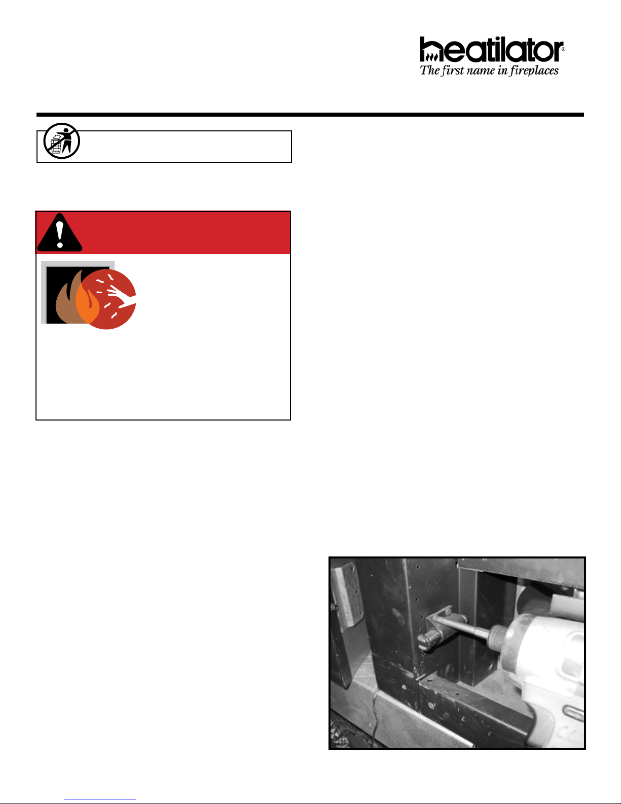
1. Locate the magnetic latches in the bottom corners of
the appliance. Using a #2 Phillips bit, remove the two
screws retaining both latches. See Figure 1.
Figure 1. Remove Screws from Magnetic Latches
1
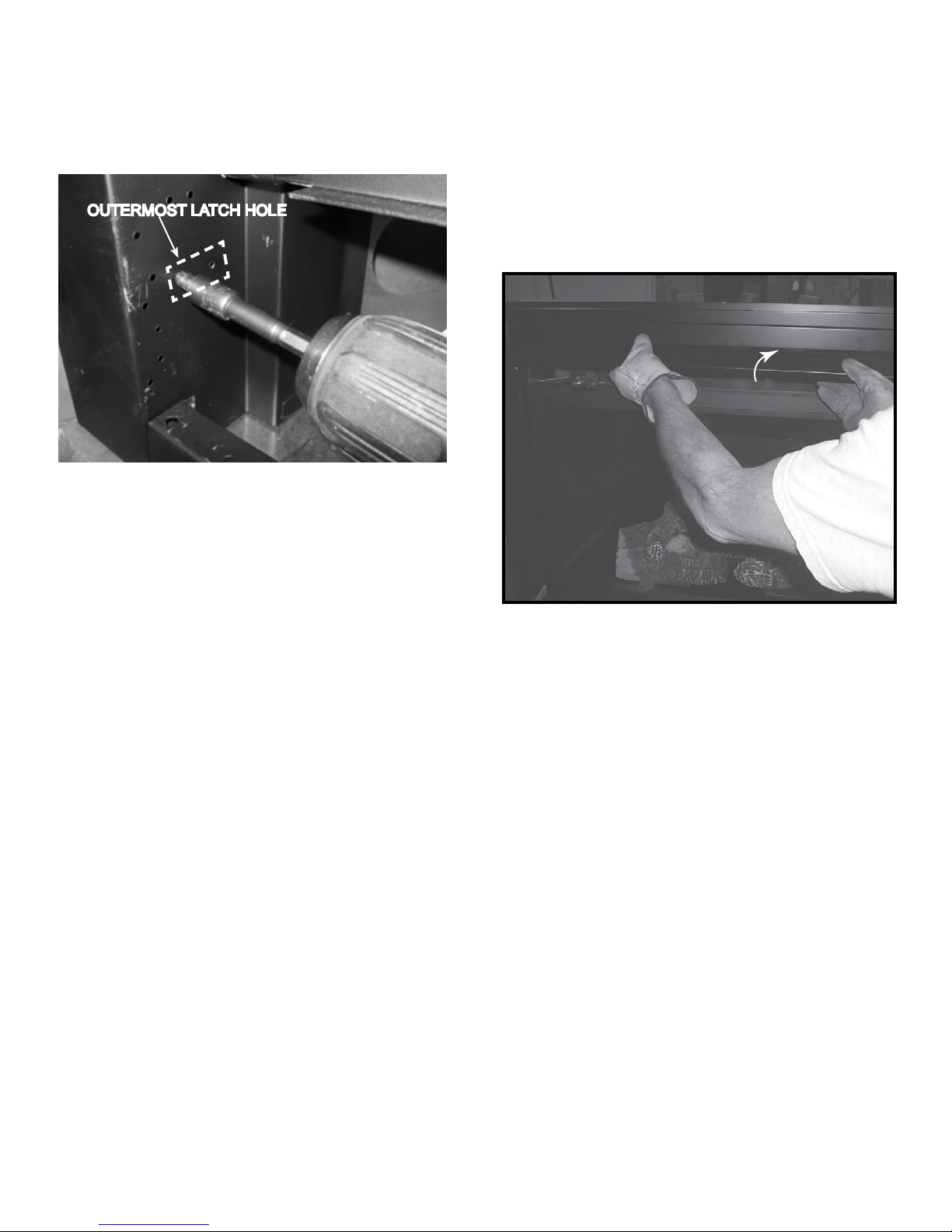
2. Install a shoulder screw in the outermost hole from
where the latches were removed. See Figure 2.
Shoulder screws are located in the manual bag. Tighten shoulder screw until snug. Do not overtighten.
OUTERMOST LATCH HOLE
Figure 2. Install Shoulder Screw (1 Per Side)
INSTALL HOOD (All Models)
1. Locate the four screws inside the upper section of the
appliance.
2. Loosen and partially unscrew all four screws about 1/8
inch using a 1/4 inch drill driver.
3. Slide the hood into position under the screw heads.
See Figure 3.
4. Using a 1/4 inch drill driver, tighten the four screws. Do
not overtighten.
Figure 3. Install Hood
2 Heatilator • SIM-3630, SIM-3933, SIM-4236, SIM-4842 Decorative Front Instructions • 2382-930 Rev. B • 9/17
 Loading...