

Heatilator MAX60L, MAX60, MAX60LE, MAX60EF, MAX60F Installation & Operating Instructions Manual
...
INSTALLATION & OPERATING
INSTRUCTIONS
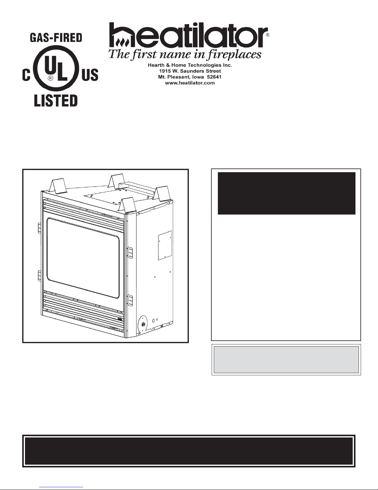
MAXUS DIRECT VENT HEATER LISTED GAS APPLIANCE
WARNING: If the information in this manual
is not followed exactly, a fire or explosion may
result causing property damage, personal injury or loss of life.
— Do not store or use gasoline or other flammable
vapors and liquids in the vicinity of this or any
other appliance.
— What to do if you smell gas
• Do not try to light any appliance.
• Do not touch any electrical switch; do not use
any phone in your building.
• Immediately call your gas supplier from a
neighbor’s phone. Follow the gas supplier’s
instructions.
• If you cannot reach your gas supplier, call the
fire department.
— Installation and service must be performed by a
qualified installer, service agency or the gas
supplier.
MAX60 (Shown with the FFMAX1 Face)
For Residential Use - Meets all HUD requirements for
manufactured housing installations.
This appliance may be installed as an OEM installation in a manufactured (mobile) home and must be installed in accordance with the manufacturer’s
instructions and the Manufactured Home Construction and Safety Standard, Title 24 CFR, Part 3280 or Standard for Installation in Mobile
Homes, CAN/CSA Z240 MH. For assistance during installation contact your local dealer or contact the Heatilator Technical Services Department,
Hearth & Home Technologies Inc., 1915 W. Saunders St., Mt. Pleasant, IA 52641. This appliance may be installed in an aftermarket permanently located,
manufactured (mobile) home, where not prohibited by local codes. This appliance is only for use with the type of gas listed on the rating plate. This
appliance is not convertible for use with other gases, unless a certified conversion kit is used.
Improper installation, adjustment, alteration, service or maintenance can cause injury or property damage. Refer to this
manual. For assistance or additional information, consult a qualified installer, service agency or the gas supplier.
09/04 30484 Rev Q 1
CAUTION:
Do not expose the appliance to the elements (such as
rain, etc.).
FOR MANUFACTURED (MOBILE) HOMES:
WARNING!
MAXUS DIRECT VENT HEATER
PLEASE RETAIN THIS MANUAL FOR FUTURE REFERENCE
TABLE OF CONTENTS
A. Listings and Code Approvals........................................................................................................................ 3
B. Appliance Specifications............................................................................................................................. 5
C. Locations and Clearances ........................................................................................................................... 7
D. Framing/Setting the Appliance..................................................................................................................... 9
E. Venting ...................................................................................................................................................... 10
F. Utilities ...................................................................................................................................................... 23
G. Finishing.................................................................................................................................................... 27
H. Appliance Preparation ............................................................................................................................... 28
I. Determining the Ignition Type .................................................................................................................... 30
J. Lighting Instructions .................................................................................................................................. 30
K. Seasonal Checklist ................................................................................................................................... 32
L. Start-up Issues .......................................................................................................................................... 33
M. Maintenance Instructions ........................................................................................................................... 34
N. Replacement Parts .................................................................................................................................... 36
O. Optional Components ................................................................................................................................ 40
Index ......................................................................................................................................................... 43
Warranty .................................................................................................................................................... 44
Note: An arrow () found in the text and in the index signifies change in content.
WARNING!
DO NOT use this appliance if any part has been under water. Immediately call a qualified service technician to inspect
the appliance and to replace any part of the control system and any gas control which has been under water.
Safety Precautions
1. Please read these installation instructions completely before beginning installation procedures. Failure to follow
them could cause an appliance malfunction resulting in serious injury and/or property damage.
2. Always check your local building codes prior to installation. This installation must comply with all local, regional,
state and national codes and regulations.
3. Installation and repair should be done by a qualified service person. This appliance should also be inspected
annually by a qualified service person. More frequent inspections/cleaning may be required due to excessive lint
from carpeting, bedding materials, etc. It is imperative that the control compartment, burners and circulating air
passageways of the appliance be kept clean.
4. This is a vented decorative gas appliance. Do not burn wood or other material in this appliance.
5. NEVER leave children unattended when there is a fire burning in the appliance.
6. This appliance may only use the approved venting systems shown in these installation instructions. Venting must
not be connected to chimney flue servicing a solid fuel burning appliance or a gas fuel burning appliance.
7. NEVER use gasoline, gasoline-type lantern fuel, kerosene, charcoal lighter fluid, or similar liquids in this appliance.
Keep any flammable liquids a safe distance from the appliance.
8. While servicing this appliance, always shut off all electricity and gas to the appliance. This will prevent possible
electrical shock or burns. Also, make sure the appliance is completely cooled before servicing.
9. Do not use this appliance if any part has been under water. Immediately call a qualified service technician to inspect
the appliance and to replace any part of the control system and any gas control which has been under water.
10. Be sure to provide adequate clearances around the air openings into the combustion chamber and adequate
accessibility clearances for servicing and proper operation.
2 30484 Rev Q 09/04
MAXUS DIRECT VENT HEATER
A. LISTINGS AND CODE APPROVALS
1. U.S. and Canadian Certification
The Maxus Series Gas Appliance has been tested in
accordance with the ANSI standard Z21.88-1998, CSA
2.33-M98, and has been listed by UL for installation
and operation as described in these installation and
operating instructions. All components are AGA, CGA,
CSA or UL safety certified.
2. Local Codes
This installation must conform with local codes or, in
the absence of local codes, with the National Fuel
Gas Code, ANSI Z223.1-latest edition in the U.S.A.,
and the CAN/CGA B149-latest edition in Canada.
The Maxus Series gas appliance has been tested
and listed for use in manufactured housing (mobile
homes). These installation instructions conform with
the Manufactured Home Construction and Safety
Standard, Title 24 CFR, Part 3280, or when such a
standard is not applicable, the Standard for
Manufactured Home Installations, ANSI A225.1.
This appliance is approved for installation in
bedrooms and manufactured housing (mobile
homes) in the United States and Canada.
3. Glass Specifications/Certifications
Heatilator gas appliances manufactured with
tempered glass may be installed in hazardous
locations such as bathtub enclosures as defined by
the CPSC. The tempered glass has been tested and
certified to the requirements of ANSI Z97.1-1984 and
CPSC 16 CFR 1202. (Safety Glazing Certification
Council SGCC# 1595 and 1597. Architectural Testing,
Inc. Reports 02-31919.01 and 02-31917.01.)
This statement is in compliance with SPCS 16 CFR
Section 1201.5 “Certification and labeling
requirements” which refers to 15 USC 2063 stating,
“…Such certificate shall accompany the product or
shall otherwise be furnished to any distributor or
retailer to whom the product is delivered.”
Some local building codes require the use of tempered
glass with permanent marking in such locations.
Glass meeting this requirement is available from the
factory. Please contact your dealer or distributor to
order.
4. Efficiency
The efficiency rating of the appliance is a product
thermal efficiency rating determined under continuous
operating conditions and was determined
independently of any installed system.
If any assistance is required during installation please
contact your local dealer or contact the Heatilator
Technical Services Department, Hearth & Home
Technologies Inc., 1915 W. Saunders St., Mt. Pleasant,
IA 52641, 1-800-927-6841.
This appliance is tested and listed for use only with the optional accessories listed in
these instructions. Use of optional accessories not specifically tested for this appliance
could void the warranty and/or result in a safety hazard.
Note: Illustrations throughout these instructions reflect typical installations and are for design purposes only. Actual
installations may vary slightly due to individual design preferences. However, minimum and maximum clearances
must be maintained at all times.
The illustrations and diagrams used throughout these instructions are not drawn to scale.
09/04 30484 Rev Q 3
WARNING!
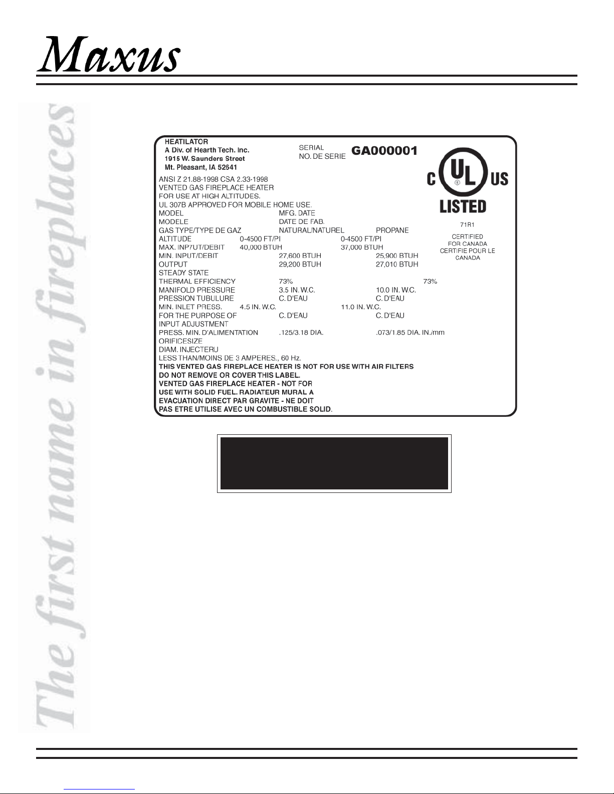
Rating Plate Located in the Heater
MAXUS DIRECT VENT HEATER
(Example only)
WARNING!
This valve has been preset at the factory. Altering
settings may result in fire hazard or bodily injury.
4 30484 Rev Q 09/04
MAXUS DIRECT VENT HEATER
B. APPLIANCE SPECIFICATIONS
Maxus Nomenclature
Catalog # Description
MA X60 38 in. w ide/36 in. glass /natural gas /standing pilot
MAX60L 38 in. w ide/36 in. glass/propane/standing pilot
MA X60F 38 in. w ide/36 in. glass/natural gas /standing pilot/f an kit
MA X60LF 38 in. w ide/36 in. glass/pr opane/standing pilot/fan kit
MA X60E 38 in. w ide/36 in. glass/natural gas /electronic ignition
MA X60LE 38 in. w ide/36 in. glass /propane/electronic ignition
MA X60EF 38 in. w ide/36 in. glass/natural gas/electronic ignition/fan kit
MA X60LEF 38 in. w ide/36 in glass/propane/electronic ignition/f an kit
FFMA X1 Black grille, black hood, bright brass trim around f lat top opening
FFMAX2 Black f illigree fr ont, black hood, bright brass trim around arched top opening
FFMAX2G Gold f illigree front, gold hood, no extra trim and arched top opening
Components Description
DRC-RADIUS Cap Shield
COOL-ADDM Cap Shield - pack of six
DVP-TV Vertical Termination Cap
DVP45 45-deg Elbow
DVP90 90-deg Elbow (for Heatilator appliances only)
DVP90ST 90-deg Starter Elbow (should be the first 90-deg elbow used)
RF6M Roof Flashing (vertical termination for 0/12 to 6/12 pitch) - pack of four
RF12M Steep Pitch Roof Flashing (for 7/12 to 12/12 pitch) - pack of six
DV P4 4 i n. length Ve nt Pi pe
DV P6 6 in. le ngth Vent P ipe
DV P12 12 in. length Vent Pipe
DVP24 24 in. length Vent Pipe
DVP36 36 in. length Vent Pipe
DVP48 48 in. length Vent Pipe
DVP6A 3-6 in. Slip Section Vent Pipe (to be used with another piece of pipe)
DVP12A 3-12 in. Slip Section Vent Pipe (to be used with another piece of pipe)
DV P12MI 12 in. Vent P ipe - non-unitized (can be cut to length)
DVP24MI 24 in. Vent Pipe - non-unitized (can be cut to length)
DVP-HVS Vent Support
DVP-WS Wall Shield to ensure horizontal clearances
DVP-FS Firestop Spacer
DVP-TRAP1 Horizontal Termination Cap with 1-3/4 in. telescoping flue and wall shield with heat shield
DVP-TRAP2 Horizontal Termination Cap with 4 in. telescoping flue and wall shield with heat shield
DV P-TB1 Basement Horizontal Termination Cap
DVP-TRAPK1 Top Vent Horizontal Kit with DVP-TRAP1 Termination Cap, wall shield with heat shield, and starter elbow
DVP-TRAPK2 Top Vent Horizontal Kit with DVP-TRAP2 Termination Cap, wall shield with heat shield, and starter elbow
DVP-HSM Extended Heat Shield
BEK Brick Extensi on K it
DVP-AS Attic Insulation Shield
09/04 30484 Rev Q 5
MAXUS DIRECT VENT HEATER
Note: Minimum and maximum clearances must be
maintained at all times. Illustrations throughout these
instructions reflect typical installations and are for design
purposes only. Actual installation may vary slightly due
to individual design preferences.
The illustrations and diagrams used throughout these
installation instructions are not drawn to scale.
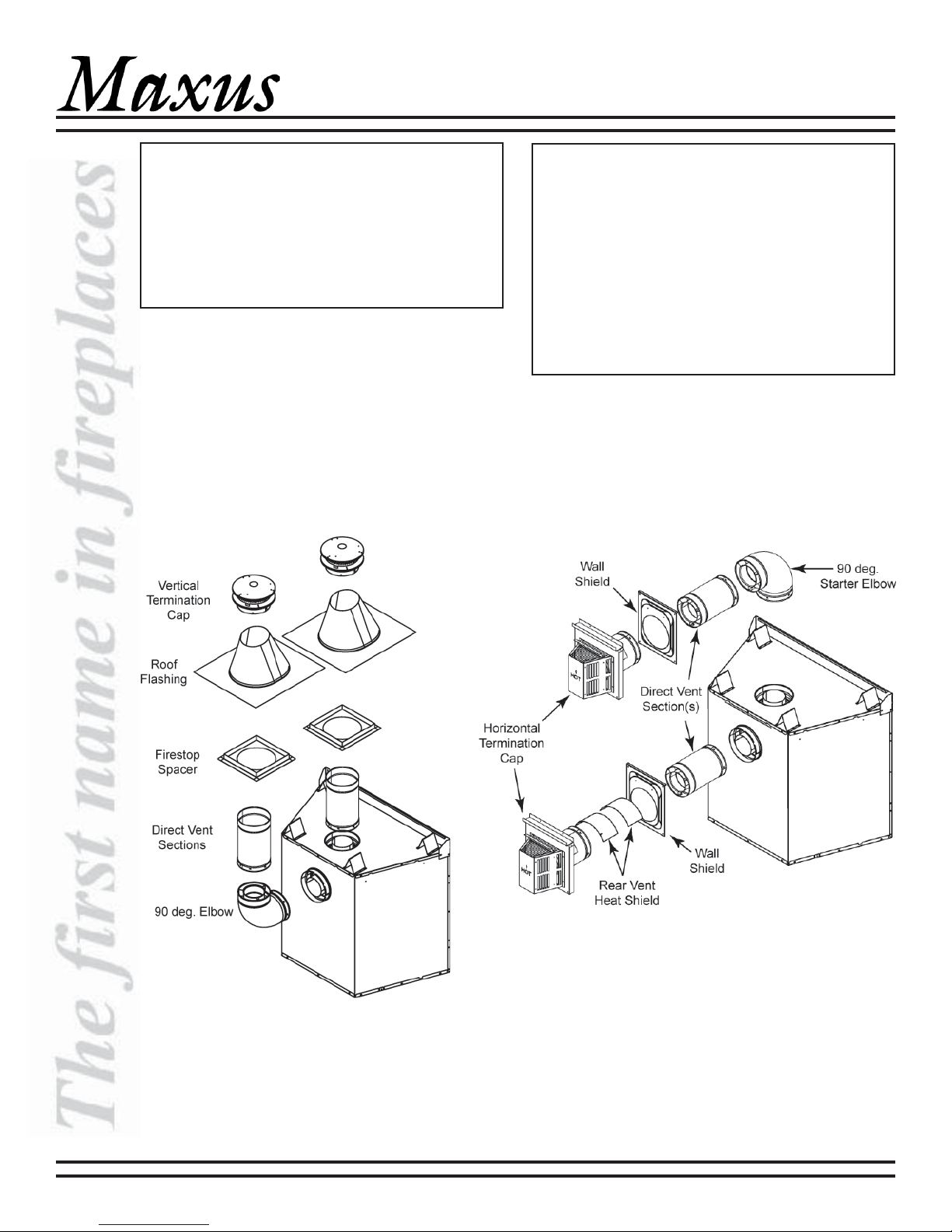
Typical Vertical Installations
(Rear and Top Vent Shown)
Tools and building supplies normally required for
installation:
Saw Wall-finishing
Pliers materials
Hammer Framing material
Phillips screwdriver Surround
Tape measure Caulking material
Plumb line Gloves
Level Framing square
Safety glasses Electric drill and bits
Non-corrosive leak-check solution
Typical Horizontal Installations
(Rear and Top Vent Shown)
6 30484 Rev Q 09/04
MAXUS DIRECT VENT HEATER
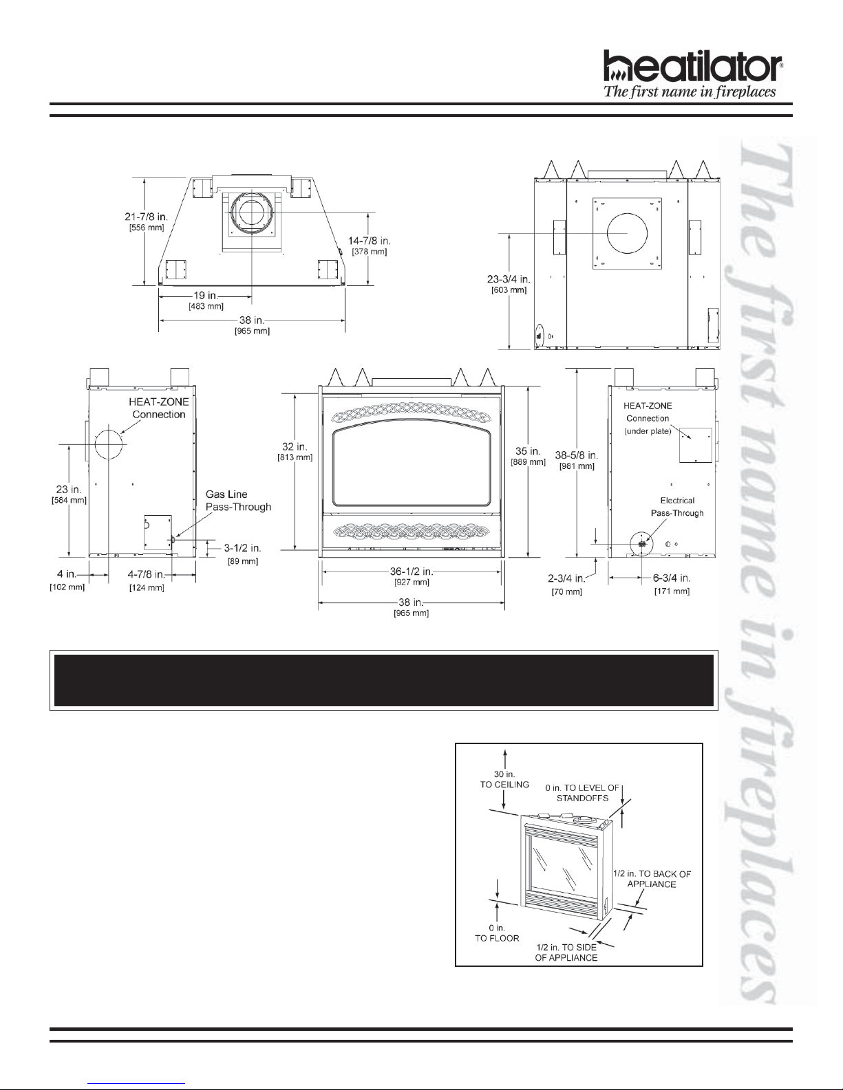
C. LOCATIONS AND CLEARANCES
Appliance Dimensions
WARNING!
Due to high temperatures, the appliance should be located out of traffic and away from furniture and draperies.
1. Clearances to Combustible Materials
Figure 1 illustrates appliance clearances to
combustible materials.
Figure 1
Appliance Clearances to
Combustible Materials
09/04 30484 Rev Q 7
MAXUS DIRECT VENT HEATER
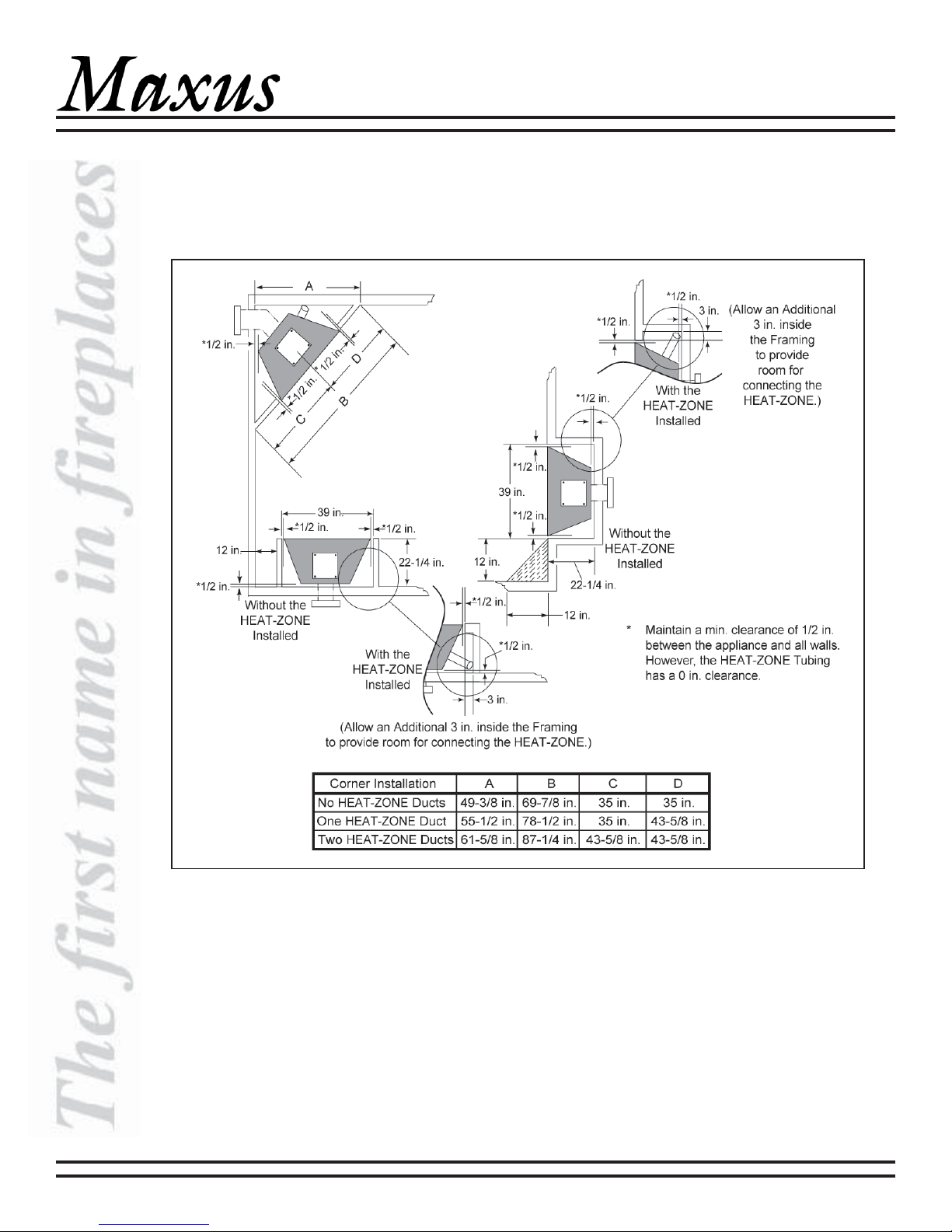
2. Locations and Space Requirements
Figure 2 illustrates different ways the appliance may be located in a room and the space required. This appliance
may be installed directly on the floor or raised on a hearth. Adjacent combustible side walls must be located a
minimum of 12 in. from the appliance. If you are using a decorative surround constructed of combustible material,
it must be located within the shaded area defined in Figure 2. Short stub walls are acceptable if they are contained
within the shaded area.
8 30484 Rev Q 09/04
Figure 2 - Appliance Locations
MAXUS DIRECT VENT HEATER
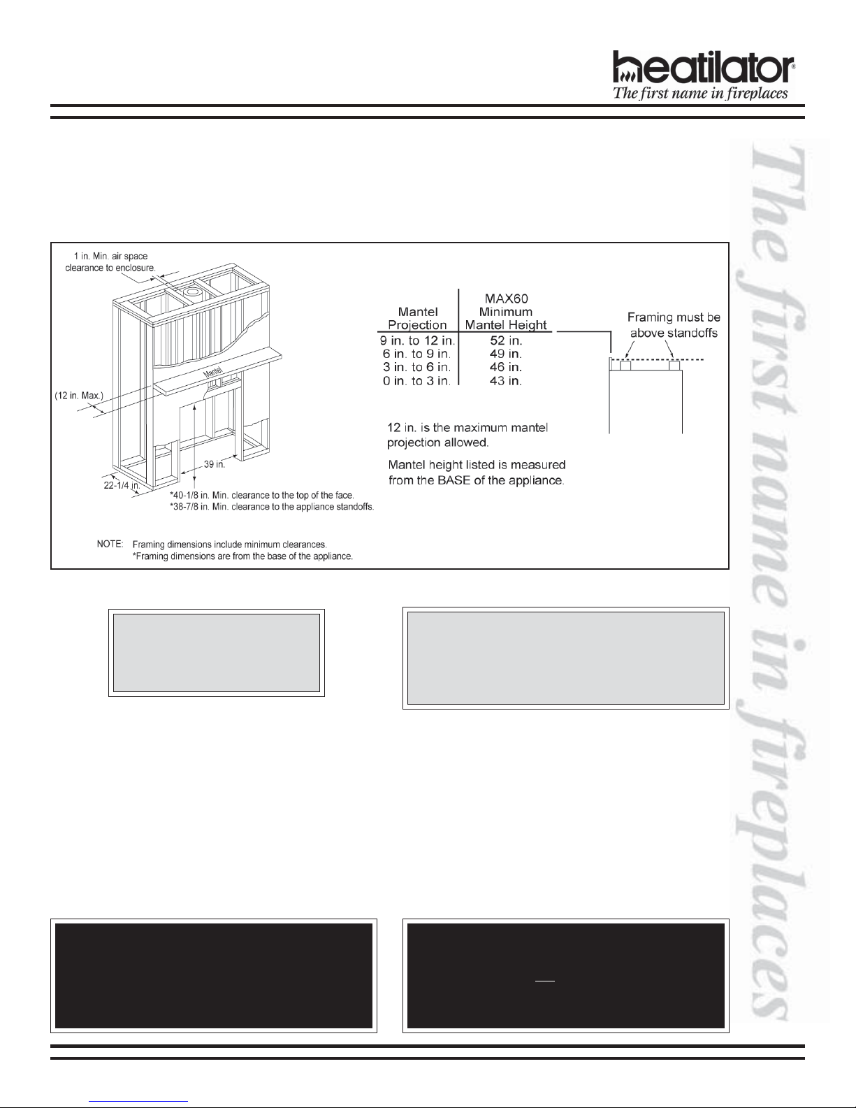
D. FRAMING/SETTING THE APPLIANCE
1. Frame the Appliance
Figure 3 shows typical framing and mantel heights of this appliance using combustible materials. All required
clearances to combustibles must be adhered to.
CAUTION:
Wear gloves and safety glasses
for protection.
2. Setting the Appliance
a. Positioning the Appliance
This appliance may be placed on a smooth combustible or noncombustible continuous, flat surface. When the
appliance is installed directly on carpeting, tile or other combustible material other than wood flooring, the
appliance shall be installed on a metal or wood panel extending the full width and depth of the appliance. Slide
the appliance into position and level the appliance from side-to-side and front-to-back. Shim with noncombustible
material as necessary.
b. Secure the Appliance
Bend out the nailing flanges on each side of the appliance and nail to framing. The nailing flanges have been
positioned 5/8 in. back from the front of the appliance to allow the addition of drywall.
WARNING!
This appliance may only use the approved venting
systems shown in these installation instructions. It
must not be connected to a chimney flue servicing a
separate solid fuel or gas fuel burning appliance.
Figure 3 - Framing
CAUTION:
Provide adequate clearances around the air
openings into the appliance and adequate
accessibility clearances for servicing and proper
operation.
WARNING!
To prevent contact with sagging or loose insulation,
the appliance must not be installed against vapor
barriers or exposed insulation. Localized overheating could occur and a fire could result.
09/04 30484 Rev Q 9
MAXUS DIRECT VENT HEATER
E. VENTING
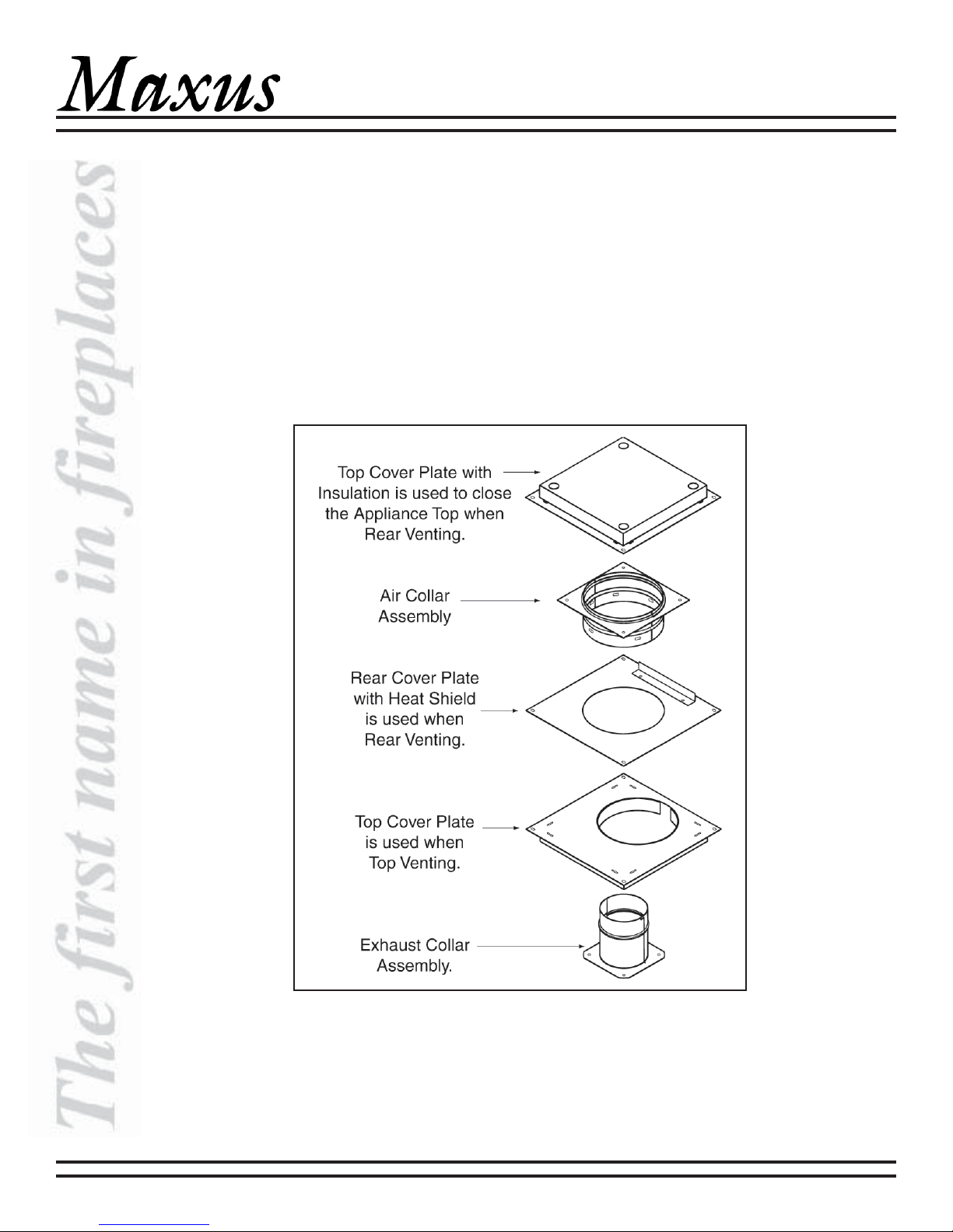
1. Remove the Vent Covers and Place the Collars
This appliance may be vented off the rear or off the top. Depending on your specific installation, a vent cover will
need to be removed from either the top or rear of the appliance and inner and outer collars attached.
Looking at the rear or top of your appliance (depending on which venting style you are going to use), there is a
square plate, and other parts (see Figure 4) held to the firebox with four screws. Remove this plate (insulation is
attached to the top one). Below this piece is another plate attached to the inner shell of the firebox. Remove this plate
as well. A third plate and gasket are attached to the firebox beneath the previous plate with four screws. Remove this
last plate.
2. The Following Venting Components are Shipped Attached to the Top of the Appliance
10 30484 Rev Q 09/04
Figure 4
Venting Components
(in order of disassembly)
MAXUS DIRECT VENT HEATER
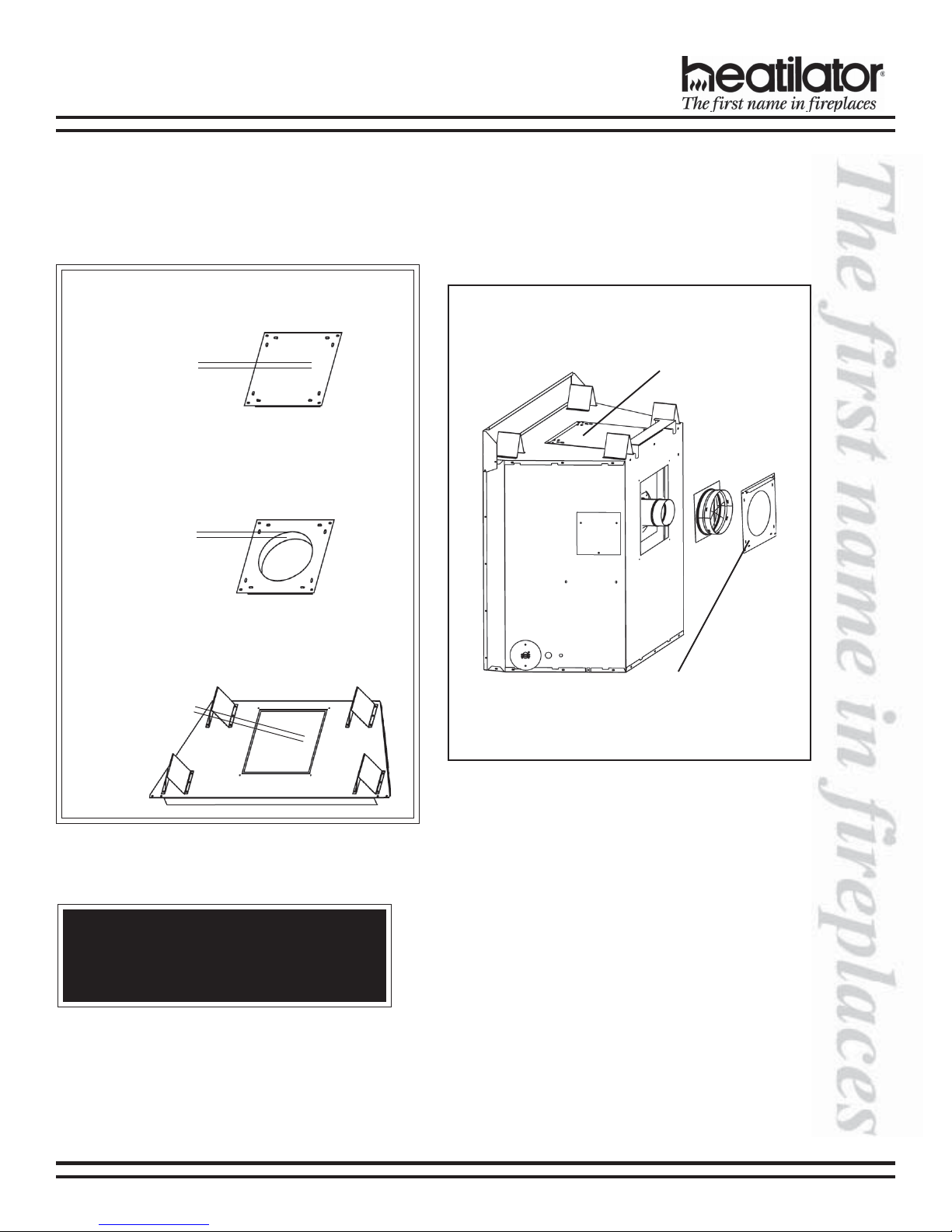
3. Rear Venting
a. Attach the collars supplied. See Figure 5.
b. When attaching the 14 in. square plate with an 8 in. hole, there is a heat shield attached. This must be up and
face out (away from the appliance).
WARNING!
When rear venting,
seal the unused top
opening with the
solid cover with the
insulation (install
with the insulation
down).
When top venting,
use the plate with an
8 in. opening and
insulation (install
with the insulation
down).
The opening on the
top of the appliance
must be sealed with
an insulated cover.
The top opening must be
enclosed with the insulated
cover.
When installing this plate, the
heat shield must face upwards
and out (away from the
appliance).
WARNING!
If not sealed, a fire hazard will be created and
the appliance will not operate properly.
09/04 30484 Rev Q 11
Figure 5
MAXUS DIRECT VENT HEATER
4. Top Venting
Use the 5 in. diameter collar assembly (with the
attached gasket) and the four screws removed earlier
to attach the collar assembly where the last plate was
removed. Take care not to strip the screws. Attach the
8 in. diameter collar assembly with four screws, to
where the second plate was removed on the inner
shell. Make sure the gasketing on the plate seals the
firebox inner shell. The third and final piece to install
has insulation attached to it and an 8 in. diameter
hole. This piece should fit around the 8 in. collar
assembly with the insulation going inside the outer
shell of the firebox. Attach with screws. See Figure 6.
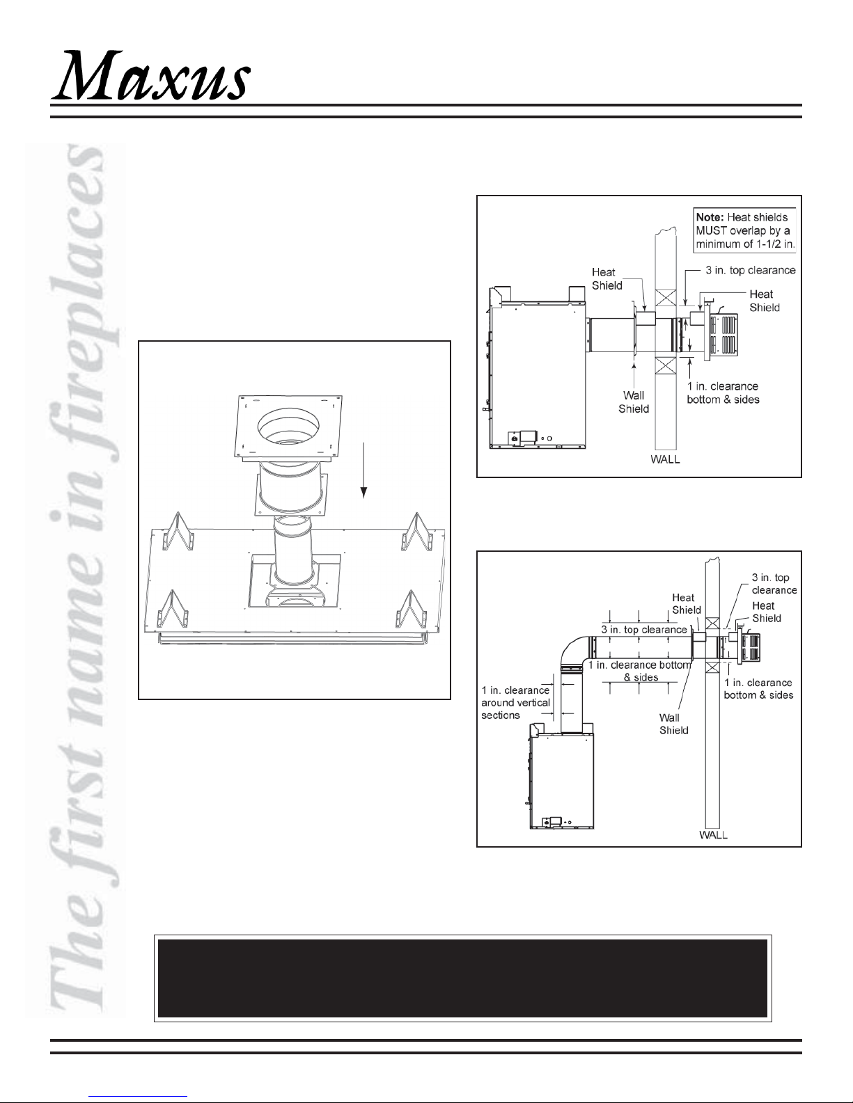
5. Horizontal Termination
a. Clearances
See Figures 7 and 8 for clearance information.
Figure 7
Venting Clearances to
Combustible Materials - Rear Venting
Figure 6
Placement of Inner and Outer collars
Always maintain minimum air space clearances or greater around the vent system. See Figures 7
and 8. Do not pack air spaces with insulation or other material.
12 30484 Rev Q 09/04
Figure 8
Venting Clearances to
Combustible Materials - Top Venting
WARNING!
MAXUS DIRECT VENT HEATER
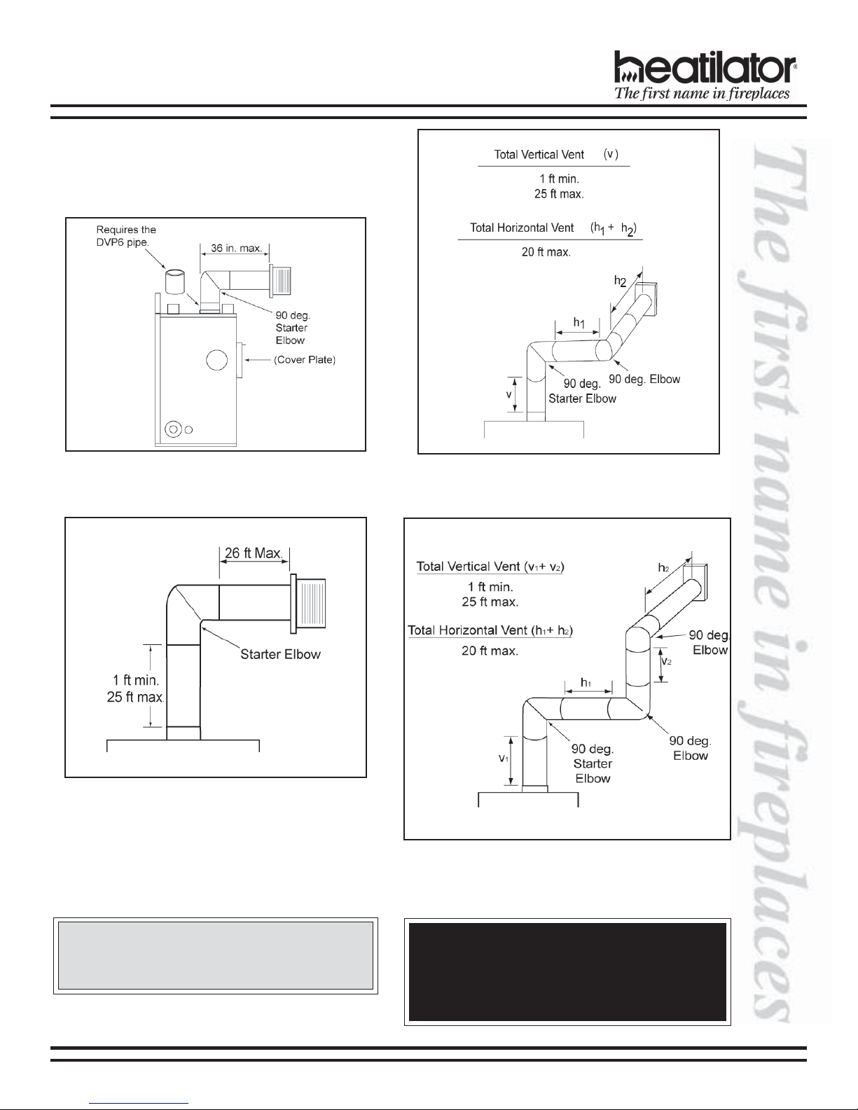
b. Vent Lengths for Top Venting (for rear venting,
see page 14)
Various venting configurations are shown in
Figures 9-12 from which maximum vent lengths
can be determined.
Figure 9
Vent Lengths with One Elbow
(Minimum Vertical)
Figure 10
Vent Lengths with One Elbow
(1 ft vertical or more, 25 ft maximum)
Figure 11
Vent Lengths with Two Elbows
Figure 12
Vent Lengths with Three Elbows
CAUTION:
Provisions shall be made to provide adequate
combustion and ventilation air.
09/04 30484 Rev Q 13
WARNING - RISK OF FIRE!
The horizontal run of vent must have a 1/4 in. rise
for every 1 ft of run towards the termination. Never
allow the vent to run downward. This could cause
high temperatures and may create a fire hazard.
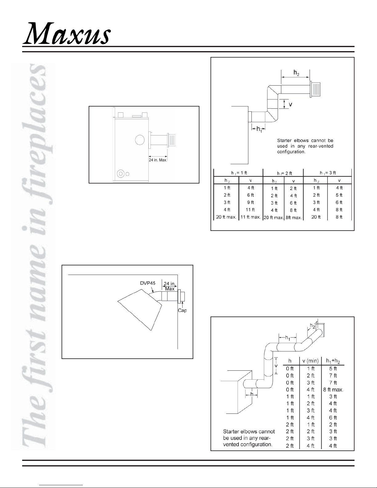
c. Vent Lengths for Rear Vent
1) No Elbows
The maximum horizontal run, with no vertical
sections of vent, is 24 in. from the back of the
appliance to the base of the cap. See
Figure 13.
Figure 13
No Elbows
2) A 45 degree Elbow
For corner installations with horizontal
venting, a maximum of one 45 degree elbow
may be used. The maximum horizontal run
following the elbow is 24 in. to the base of
the cap and will include a 45 degree elbow
and a termination cap. See Figure 14.
MAXUS DIRECT VENT HEATER
Figure 15 - Two Elbows
4) Three Elbows
Elbows used on rear vented configurations
should be either a 90 degree elbow or a
45-deg elbow. A starter elbow cannot be
used in any rear-vented configuration.
Figure 16 shows various venting
configurations using three elbows to
terminate horizontally.
Starter elbows cannot
be used in any rearvented configuration.
Figure 14
One 45 degree Elbow
3) Two Elbows
Elbows used on rear vented venting
configurations should be either a 90 degree
elbow or a 45 degree elbow. A starter elbow
cannot be used in any rear-vented
configuration. Figure 15 shows various
venting configurations using two elbows to
terminate horizontally.
14 30484 Rev Q 09/04
Figure 16 - Three Elbows
 Loading...