

Heatilator G270, G270L, G270E, G270LE, G270M Installation Instructions Manual
...
INSTALLATION
INSTALLATION INSTRUCTIONS - G270 SERIES
B - VENT GAS APPLIANCE
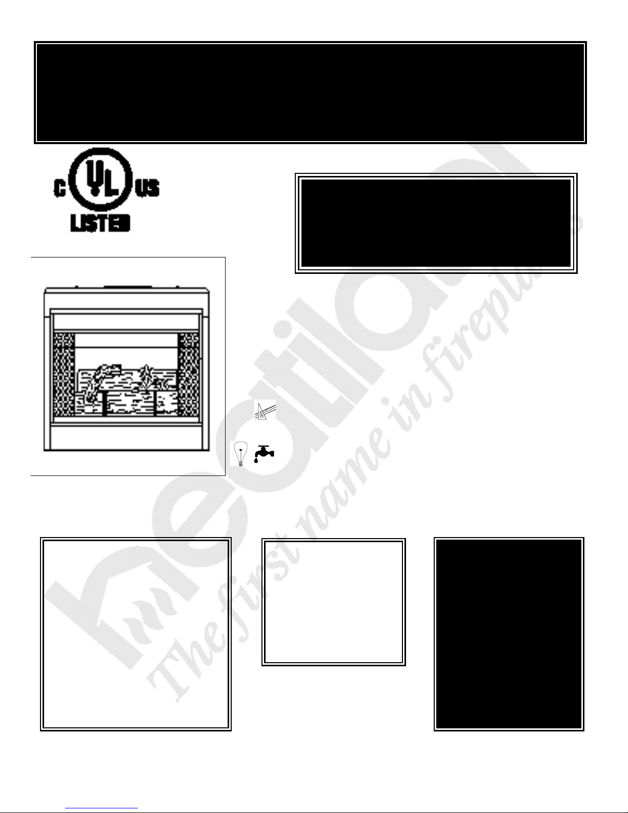
The G270 B-Vent Gas Appliance
Scroll to Page 14o for the
“Operating and
Maintenance Instructions.”
Read these Installation Instructions completely before beginning
installation. Failure to follow them could cause an appliance malfunction resulting in serious injury and/or property damage.
TABLE OF CONTENTS
A. Preparation..............................................................
B. Location and Clearances.........................................
C. Framing....................................................................
D. Setting The Unit.......................................................
E. Venting.....................................................................
F. Utilities.....................................................................
G. Finishing.................................................................
H. Firebox Preparation................................................
2i
3i
4i
5i
5i
8i
11i
11i
FOR YOUR SAFETY
What to do if you smell gas:
• Do not try to light any appliance.
• Do not touch any electrical
switch.
• Do not use any phone in your
building.
• Immediately call your gas supplier from a neighbor’s phone.
Follow the gas supplier’s
instructions.
• If you cannot reach your gas
supplier, call the fire department.
Heatilator 1915 W. Saunders Street Mt. Pleasant, IA 52641 A Division of Hearth Technologies Inc.
11-98 30094 Rev C
FOR YOUR SAFETY
Do not store or use
gasoline or other
f l a m m a ble va p o rs
and liquids in the
vicinity of this or any
other appliance.
WARNING!
I m p roper installation,
adjustment, alteration,
s e rvice or maintenance
can cause injury or
property damage. Refer
to this manual. For
assistance or add i t i o n a l
i n formation, consult a
qualified installer, service age n cy or the gas
supplier.

9-98 2i 30094B
G270 SERIES B - VENT GAS APPLIANCE
A. PREPARATION
U.S. and Canada Certification.
The G270 Gas Appliance has been tested in accordance with the ANSI standard Z21.50b-1996 in the
United States. In Canada, the current CAN/CGA
M2.22-M96 and have been LISTED by Underwriters
Laboratories Inc. for installation as described in this
manual. All components are UL, AGA, CGA or CSA
safety certified.
Local Codes.
This installation must conform with local codes. In the
absence of local codes comply with the National Fuel
Gas Code, ANSI Z223.1-latest edition, in the U.S.A.
and the CAN/CGA B149, Installation Codes, in
Canada.
G270 Nomenclature
Catalog # Description
G270 Standing Pilot, Natural Gas
G270L Standing Pilot, L.P. Gas
G270E Electronic Ignition, Natural Gas
G270LE Electronic Ignition, L.P. Gas
G270M Standing Pilot, Natural Gas, Millivolt System
G270LM Standing Pilot, L.P. Gas, Millivolt System
For assistance during installation contact your local
dealer or contact Heatilator Customer Relations
Department, 1915 W. Saunders Street, Mt. Pleasant,
Iowa 52641.
HEATILATOR®is a registered trademark of
Heatilator, a Division of Hearth Technologies Inc.
We strongly recommend that you DO NOT
install B-Vent Gas Appliances in strong negative air locations, such as a basement or a public facility. Living rooms with cathedral ceilings
could be susceptible to a negative air situation,
but such installations can be overcome through
raising the termination, depending on specific
installations. This fireplace uses room air for
normal operation and could have problems
establishing a positive draft in negative air locations. in lieu, we recommend a direct vent
appliance.
Catalog # Optional Components
FF270* Glass Doors and Surround Kit
RC4 Remote Control Kit - Millivolt Valve
RC5 Remote Control Kit - Electronic Ignition
RC6 Remote Control Kit - Millivolt Valve - Battery Operated
*FF270 is not compatible with units with Date Codes
prior to 54195.
Note: Minimum and maximum clearances must
be maintained at all times. Illustrations
throughout these instructions reflect typical
installations and are for design purposes only.
Actual installation may vary slightly due to individual design preferences.
The illustrations and diagrams used throughout
these installation instructions are not drawn to
scale.
Tools and building supplies normally
required for installation:
Tools Building Supplies
Saw Wall-finishing materials
Pliers Framing material
Hammer Fireplace surround
Phillips screwdriver Caulking material
Tape measure
Plumb line
Level
Electrical drills/bits
Square
Gloves
G270 SERIES B - VENT GAS APPLIANCE
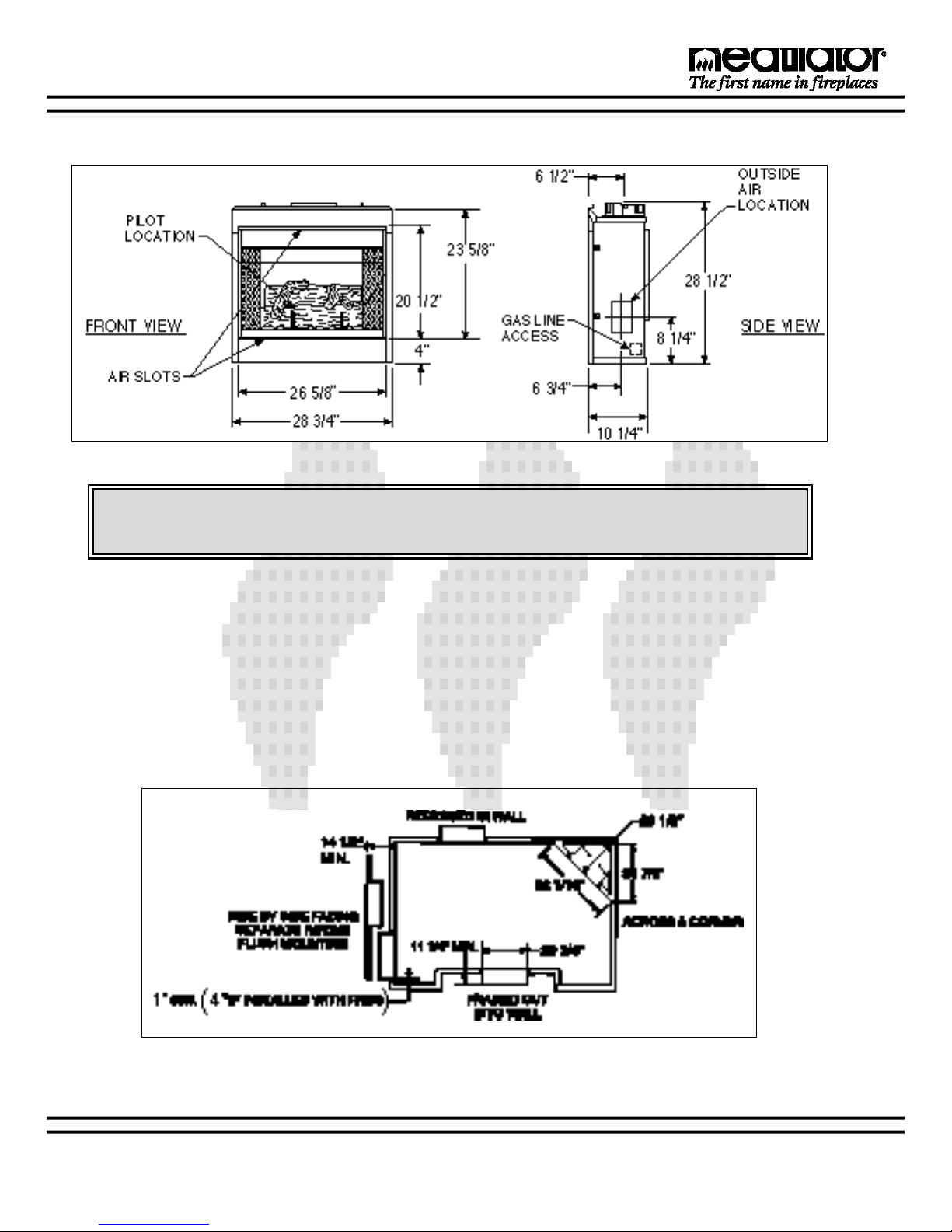
B. LOCATION AND CLEARANCES (In inches)
DUE TO HIGH TEMPERATURES, THE APPLIANCE SHOULD BE LOCATED OUT OF TRAFFIC
AND AWAY FROM FURNITURE AND DRAPERIES.
Figure 1 - Unit Dimensions
1. APPLIANCE LOCATIONS AND SPACE
REQUIREMENTS
Figure 2 illustrates a variety of ways the appliance may
be located in a room. The G270 may be installed
directly on the floor or raised on a hearth.
2. CLEARANCES
1. For unit:
Top of stand-offs 0”
Floor 0”
Back of unit 1”
Side 1”
Face to ceiling 30”
7-98 3i 30094A
Figure 2
Appliance Locations
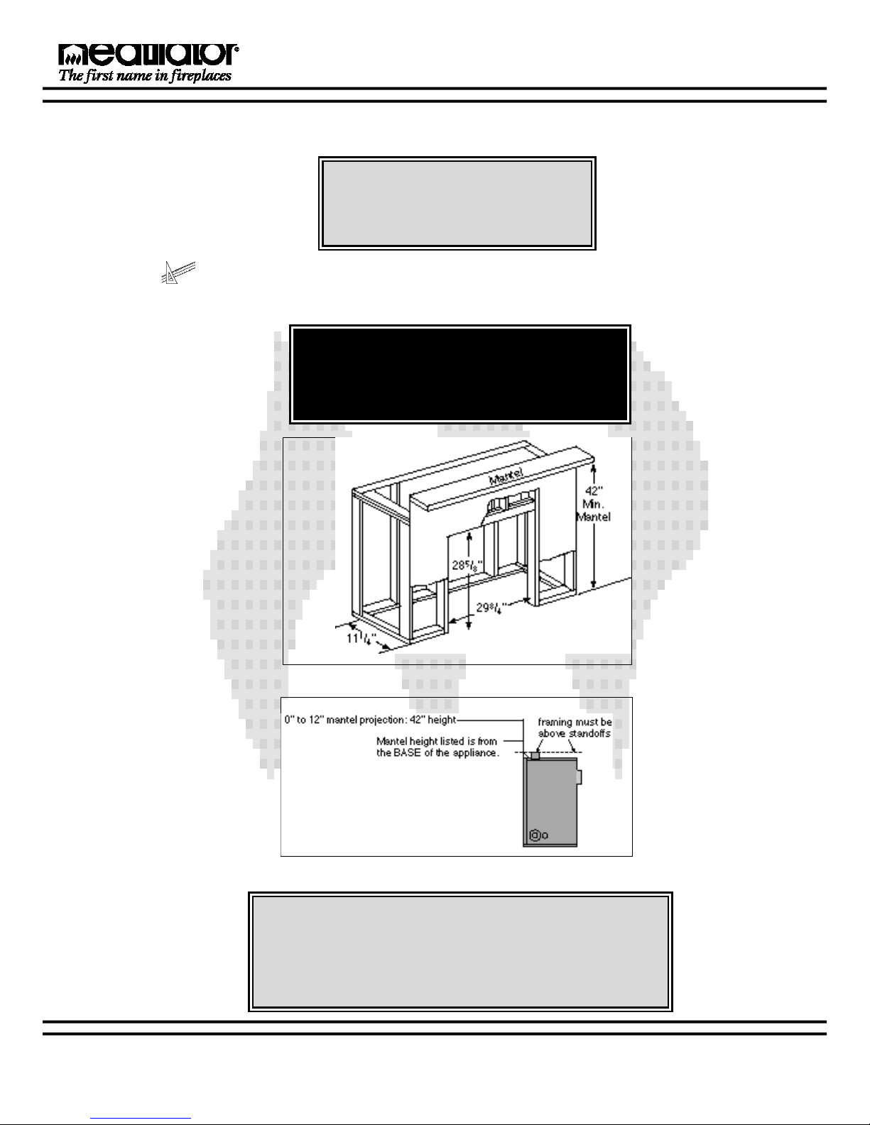
C. FRAMING
Figure 3a - Framing
Figure 3a shows a typical framing of this appliance using combustible materials. Figure
3b shows the mantel heights for mantel projections. All required clearances to combustibles must be adhered to.
CAUTION
WEAR GLOVES AND SAFETY
GLASSES FOR PROTECTION.
CAUTION
PROVIDE ADEQUATE CLEARANCES AROUND THE AIR
OPENINGS INTO THE COMBUSTION CHAMBER AND ADEQUATE ACCESSIBILITY CLEARANCES FOR SERVICING
AND PROPER OPERATION.
G270 SERIES B - VENT GAS APPLIANCE
ALWAYS MAINTAIN MINIMUM AIR SPACE
CLEARANCES OR GREATER AROUND THE
APPLIANCE AND CHIMNEY SYSTEM.
WARNING - RISK OF FIRE!
7-98 4i 30094A
Figure 3b - Framing
7-98 5i 30094A
G270 SERIES B - VENT GAS APPLIANCE
D. SETTING THE UNIT
1. Positioning the Firebox.
This appliance may be placed on a smooth
combustible or non-combustible, continuous
flat surface. When the appliance is installed
directly on carpeting, tile or other combustible
material other than wood flooring, the appliance
shall be installed on a metal or wood panel
extending the full width and depth of the appli-
E. VENTING
WARNING - RISK OF FIRE!
AIR SPACE CLEARANCES MUST BE MAINTAINED AT ALL TIMES.
ance. Slide the unit into position and level the appliance from side-to-side and front-to-back. Shim with
non-combustible material as necessary.
Secure the appliance by bending out the Nailing
Flanges on each side of the appliance and nail to
Framing. The Nailing Flanges have been positioned
5/8" back from the front of the unit to allow the addition of drywall.
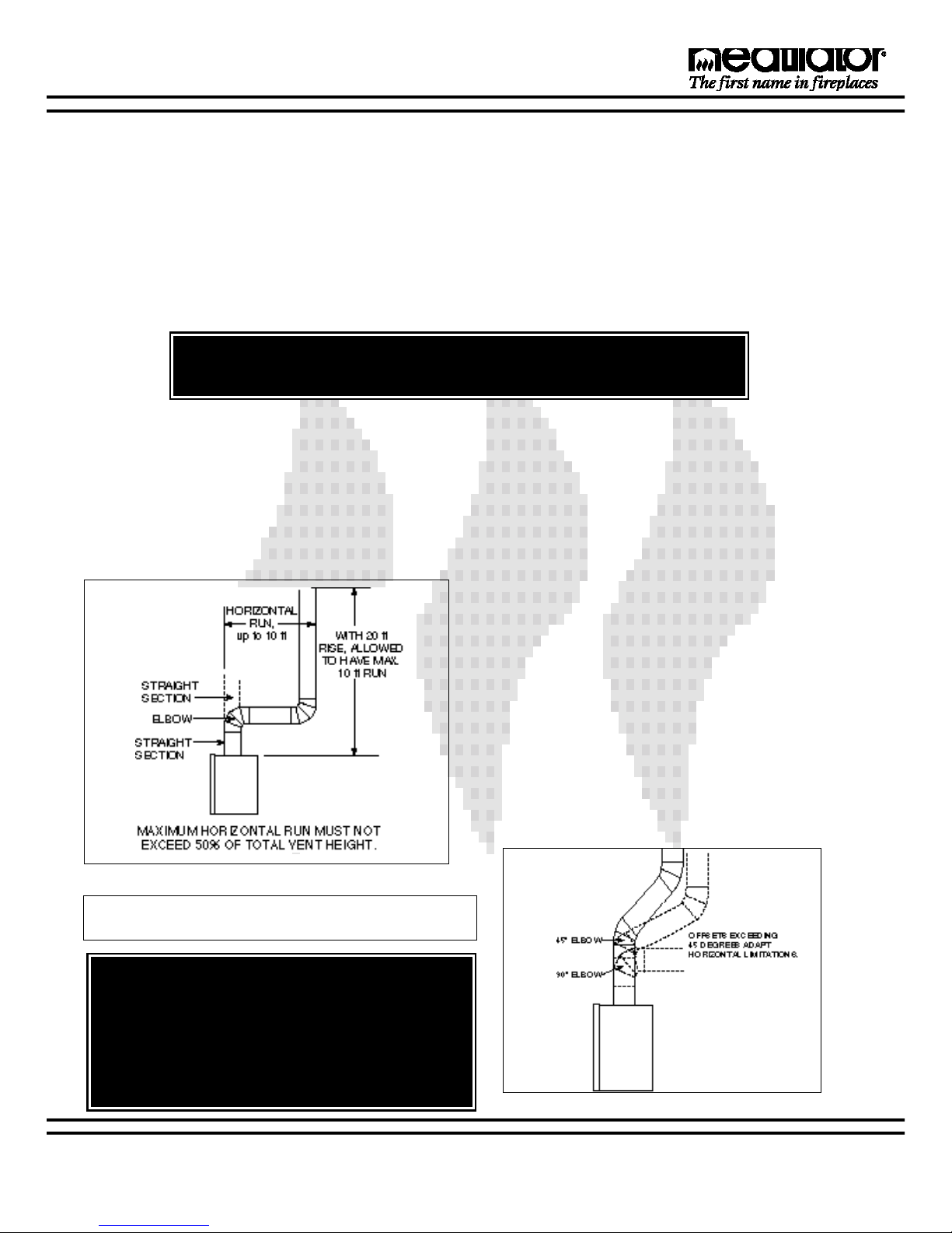
1. Vent Height.
This appliance requires a 4” B-vent for operation. Never
downsize pipe! It must be terminated above the roof line.
Follow all B-vent requirements and installation instructions,
including minimum clearances.
The minimum height of vent installation must be nine feet
from the top or 12 feet from the base of the appliance.
Horizontal run must never exceed 50% of the height of the
vent system as shown in Figure 4.
2. Attaching Venting.
a. Assembling Vent Sections. Attach a straight Vent
Section to the top of the appliance. Use only B-vent
sections.
b. Using Elbows. Elbows exceeding 45° from the vertical shall be considered horizontal and therefore adapt
horizontal run limitations. See Figure 5.
c. Penetrating the Ceiling. Mark and cut out an opening in the ceiling for a Firestop Spacer. Frame the opening with the same size of lumber used in the Ceiling
Joists.
d. Installing the Firestop Spacers. Firestop Spacers
must be used whenever the Venting penetrates a ceiling/floor area. In all situations, Firestop Spacers are to
be nailed to the Ceiling Joists from the bottom or appliance side, EXCEPT when the space above is an insulated ceiling or attic space. In this situation, the Firestop
Spacer must be secured from the top side to meet fire
stopping requirements.
Install the Firestop Spacer by positioning and securing
the four sides of the Firestop Spacer to the Joists using
a minimum of [3] Fasteners per side..
Figure 4 - Venting Off the Top of Appliance
NOTE: Vertical rise off the top of the unit before elbowing creates a less restrictive venting environment.
WARNING - RISK OF FIRE!
THE HORIZONTAL RUN OF VENT MUST HAVE A
1/4” RISE FOR EVERY 1 FT. OF RUN TOWARDS
THE TERMINATION. NEVER ALLOW THE VENT
TO RUN DOWNWARD. THIS COULD CAUSE
HIGH TEMPERATURES AND MAY PRESENT A
FIRE HAZARD.
Figure 5 - Using Elbows
7-98 6i 30094A
PROVISIONS SHALL BE MADE TO PROVIDE ADEQUATE COMBUSTION AND VENTILATION AIR.
e. Securing Vent System. Continue assembling the Vent
Sections up through the Firestop Spacers as needed. Vent
Sections must be locked into position. Elbows and Chimney
Stabilizers have straps for securing these parts to Joists or
Rafters.
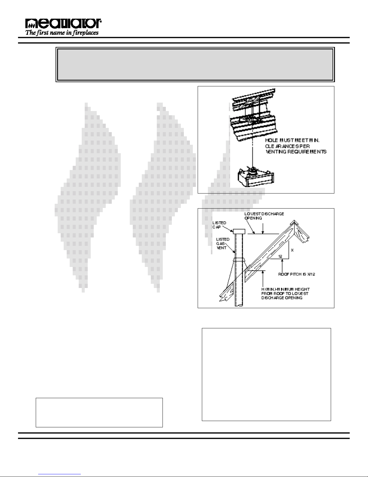
f. Marking the Exit Point in the Roof. Locate the point
where the Venting will exit the roof by plumbing down to the
center of the Vent System. Drive a nail up through the roof
to mark the center. See Figure 6a.
g. Cutting Out the Hole in the Roof. Measure to either
side of the nail and mark the opening required to meet minimum clearances per Venting requirements. This is mea-
sured on the horizontal; actual length may be larger depend-
ing on the pitch of the roof. Cut out and frame the opening.
See chapter 25 of the Uniform Building Code for Roof
Framing details.
A one inch or greater minimum air space clearance (see
Vent Instructions) must be maintained between the vent
section and the roof.
h. Install Roof Flashing or Site-produced Chase Top.
Position a Roof Flashing or a site-produced Chase Top and
secure into place.
i. Assembling Vent Sections. Continue to add vent s e c-
tions through the roof opening, maintaining minimum air
space clearance.
j. Termination Cap. Major building codes specify a mini-
mum termination height above the roof top depending on the
roof pitch. It is strongly recommended that the cap should
be at least 2’ higher than anything within 10’ of it, and a min-
imum of 3’ out of the roof. This will help to ensure the best
air flow.
Unlisted Cap. If you are using an unlisted Termination
cap and your Vent Section is at least 8 feet from a vertical
wall, follow the information in Figure 6b and Table 1 to determine the allowable termination height and location.
G270 SERIES B - VENT GAS APPLIANCE
CAUTION
Figure 6a - Roof Exiting
Figure 6b - Vent Height for Vertical Termination
Measure the roof pitch. (Roof pitch is X/12 as shown in
Figure 6b.) Find your roof pitch in Figure 8 to determine the
minimum height the Termination Cap must be located from
the point where the Vent Section penetrates the roof (H in
Figure 6b).
Listed Cap. If you are using a listed Termination Cap, you
must follow the manufacturer’s installation instructions for
minimum clearances to roof and any obstructions.
Note: Be sure to provide intermediate support
for the vent during construction and check to
be sure inadvertent loading has not dislodged
the vent from the appliance or any vent joint.
Roof Pitch H (Min.) Ft.
Flat to 6/12 ...........................................1.0
6/12 to 7/12 ..........................................1.25
Over 7/12 to 8/12..................................1.5
Over 8/12 to 9/12..................................2.0
Over 9/12 to 10/12................................2.5
Over 10/12 to 11/12..............................3.25
Over 11/12 to 12/12..............................4.0
Over 12/12 to 14/12..............................5.0
Over 14/12 to 16/12..............................6.0
Over 16/12 to 18/12..............................7.0
Over 18/12 to 20/12..............................7.5
Over 20/12 to 21/12..............................8.0
Table 1 - Vent Height
7-98 7i 30094A
G270 SERIES B - VENT GAS APPLIANCE
WARNING:
WARNING - RISK OF FIRE!
A Gas appliance must not be con-
nected to a chimney flue serving a
separate Solid - Fuel Burning appli-
ance.
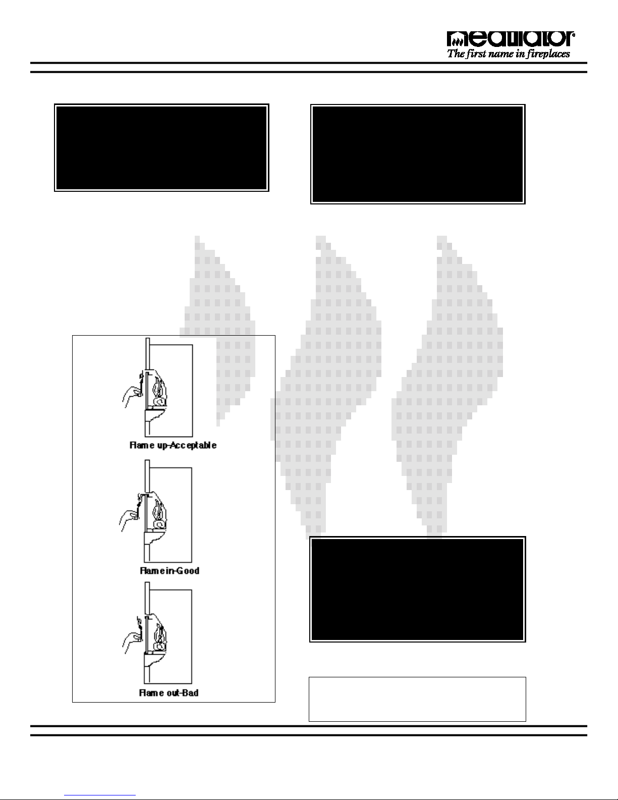
3. Check Venting System.
Check the Venting System to assure proper operation. This can be done with a match while the unit is operati n g .
Hold a lighted match at the bottom edge of the Drafthood opening. If the flames and smoke remain upright, ventilation is acceptable. If the flames and smoke are drawn into the Drafthood, this means ventilation is good. If
the flames and smoke are forced away from the Drafthood, this may indicate a ventilation blockage or down draft
resulting in gas spillage into the home. If this occurs, turn off the fireplace and do not burn it until it has been
inspected by a qualified service person. See Figure 7.
ALWAYS MAINTAIN MINIMUM CLEARANCES OR GREATER AROUND THE
CHIMNEY SYSTEM. DO NOT PACK AIR
SPACES WITH INSULATION OR OTHER
MATERIAL.
4. Installing an Outside Air Kit (strongly recom-
m e n d e d ) .
An AK14 Outside Air Kit should be purchased as a feature with this fireplace. An Outside Air Kit helps to
decrease the amount of room air taken, by utilizing outside air for combustion. The Outside Air Kit can only be
installed on the left side of the fireplace. Remove the
Outside Air Knock-out located behind the Gas Access
Panel. Install the AK14 as detailed in the installation
instructions provided with the Kit.
Figure 7 - Testing Ventilation
A maximum of 40’ of Air Kit ducting is allowed. The Air
Kit must terminate at least four feet below the venting
termination and must terminate to the outside.
WARNING!
Exhaust products of gasoline engines are
hazardous. The outside air must not be
taken from a garage space, attic spaces,
basements, or above the roofing where
other heating appliances, fans, or chimneys exhaust or utilize air.
NOTE: The Outside Air Kit can terminate at any
level with the exception that it must terminate at
least one foot below the chimney Terminal Cap.
 Loading...