

Heatilator G141, G141L, G141E, G141LE Owner's Manual
Heatilator
WARNING!
Installation and service must be performed by a qualified installer, service agency or the gas supplier.
Improper installation, adjustment, alteration, service or maintenance can cause injury or property damage. Refer to this manual. For assistance or additional information, consult a qualified installer, service agency or the gas supplier.
1915 W. Saunders Street
Mt. Pleasant, IA 52641
A Division of Hearth Technologies Inc.
G141 SERIES B-VENT GAS APPLIANCE
OWNERS MANUAL
AND INSTALLATION INSTRUCTIONS
MODELS G141, G141L, G141E, G141LE
WARNING: If the information in this manual
is not followed exactly, a fire or explosion may
result causing property damage, personal injury or loss of life.
Do not store or use gasoline or other flammable
vapors and liquids in the vicinity of this or any
other appliance.
What to do if you smell gas
Do not try to light any appliance.
Do not touch any electrical switch; do not
use any phone in your building.
Immediately call your gas supplier from a
neighbors phone. Follow the gas suppliers
instructions.
If you cannot reach your gas supplier, call
the fire department.
Installation and service must be performed by
a qualified installer, service agency or the gas
supplier.
CAUTION:
Do not expose the fireplace to
the elements (such as rain, etc.)
10-00 1 32921 Rev A
This manual must be used for installation of the
G141 Series Gas Appliance and retained by the
homeowner for operation and maintenance
instructions.

G141 SERIES B-VENT GAS APPLIANCE
Table of Contents
A. Preparation ..................................................................................................................... 3
B. Locations & Clearances .................................................................................................. 5
C. Framing ........................................................................................................................... 6
D. Setting the Fireplace ........................................................................................................ 6
E. Venting ............................................................................................................................ 7
F. Utilities .......................................................................................................................... 10
G. Finishing Materials. ........................................................................................................ 15
H. Firebox Preparation ....................................................................................................... 16
J. Lighting Instructions ....................................................................................................... 18
K. Seasonal Checklist ........................................................................................................ 20
L. Maintenance Instructions ................................................................................................ 21
M. Trouble Shooting ............................................................................................................ 24
N. Optional Components .................................................................................................... 26
O. Replacement Parts ........................................................................................................ 27
Safety Precautions
1. Please read these installation instructions
completely before beginning installation
procedures. Failure to follow them could cause a
malfunction resulting in serious injury and/or
property damage.
2. Always check your local building codes prior to
installation. The installation must comply with all
local, regional, state and national codes and
regulations.
3. Installation and repair should be done by a
qualified service person. This appliance should
also be inspected annually by a qualified service
person. More frequent inspections/cleaning may
be required due to excessive lint from carpeting,
bedding material, etc. It is imperative that the
control compartment and burners of the
appliance be kept clean.
4. The G141 is a vented gas fireplace. Do not burn
wood or other material in this appliance.
5. NEVER leave children unattended when there is
a fire burning in the fireplace.
6. This appliance must be vented with a minimum
5 B-Vent system and must terminate above the
roof line. Venting must not be connected to a
chimney flue servicing a solid fuel burning
appliance.
7. Use only the fuel gas specified on the rating label
of this gas appliance.
8. The appliance area shall be kept clear and free
from combustible materials, gasoline and other
flammable vapors and liquids.
9. While servicing this appliance, always shut off all
electricity and gas to the fireplace. This will prevent
possible electrical shock or burns. Also, make
sure the fireplace is completely cooled before
servicing.
10. The appliance and its individual shut-off valve
must be disconnected from the gas supply piping
system during any pressure testing of that system
at test pressures in excess of 1/2 psi (3.5 kPa).
11. Do not use this appliance if any part has been
under water. Immediately call a qualified service
technician to inspect the appliance and to replace
any part of the control system and any gas control
which has been under water.
12. Be sure to provide adequate clearances around
the air openings into the combustion chamber
and adequate accessibility clearances for
servicing and proper operation.
13. Provisions shall be made to provide adequate
combustion and ventilation air. The flow of
combustion and ventilation air should not be
obstructed.
32921 Rev A 2 10-00

G141 SERIES B-VENT GAS APPLIANCE
A. PREPARATION
1. CERTIFICATION.
The G141 Series Gas Fireplace has been tested in
accordance with the standard ANSI Z21.50-1998CGA 2.22-M98. The G141 has been certified by
Underwriters Laboratories Inc. for installation and
operation as described in these Installation
Instructions. All components are AGA or UL safety
certified.
2. LOCAL CODES.
Check with your local building code agency prior
to installing this appliance to ensure compliance
with local codes, including the need for permits
and follow-up inspections. This appliance must
conform with local codes, or in the absence of local
codes, comply with the National Fuel Gas Code,
ANSI Z223.1-latest edition in the U.S.; in Canada,
the CANI-B149-latest edition.
3. OPTIONAL COMPONENTS.
This gas appliance has been tested and listed for
use with the optional components listed below.
Many optional components may be purchased
separately and installed at a later date. However,
installation of a remote control will require electrical
power. To avoid costly reconstruction, a separate
course of electrical power should be supplied to
the fireplace at the time of initial installation of the
system for possible addition of these accessories
at a later date.
4. FUEL.
Any additions, changes or conversions required
in order for the appliance to satisfactorily meet
the application needs, must be made by a
qualified service technician using factory
specified and approved parts.
This product is manufactured to use natural gas or
propane gas, depending on model purchased. A
natural gas fireplace can be converted to use
propane gas later, but only if done by a qualified
service technician and only if the CKP Natural Gas
to Propane Gas Conversion Kit is used. In the event
your appliance must be converted to natural gas
from propane, you must use a CKN Propane Gas
to Natural Gas Conversion Kit.
If any assistance is required during installation, please
contact your local dealer or contact Heatilator, Technical
Services Department, 1915 W. Saunders Street, Mt.
Pleasant, Iowa 52641.
HEATILATOR® is a registered trademark of Heatilator,
a Division of Hearth Technologies Inc.
The G141 Series is a vented gas fireplace. While a significant amount of heat is created by the G141, it is not
intended to be and, therefore, should not be used as a heater.
The G141 B-Vent Gas Appliance
must consist of the following:
1. Fireplace
2. B-Vent System
3. Termination
Tools and building supplies normally required
for installation:
Saw Wall-finishing materials
Pliers Framing material
Hammer Fireplace surround
Phillips screwdriver Caulking material
Tape measure Plumb line
Level Electric drill/bits
Square
Note: Illustrations throughout these instructions
reflect typical installations and are for design
purposes only. Actual installation may vary slightly
due to individual design preferences. However,
minimum and maximum clearances must be
maintained at all times.
Optional components include:
1. Remote Control
2. Outside Air Kit
3. Glass Doors
4. Refractory Upgrade
5. Quick Tile Trim
6. ID4
7. UD4
10-00 3 32921 Rev A
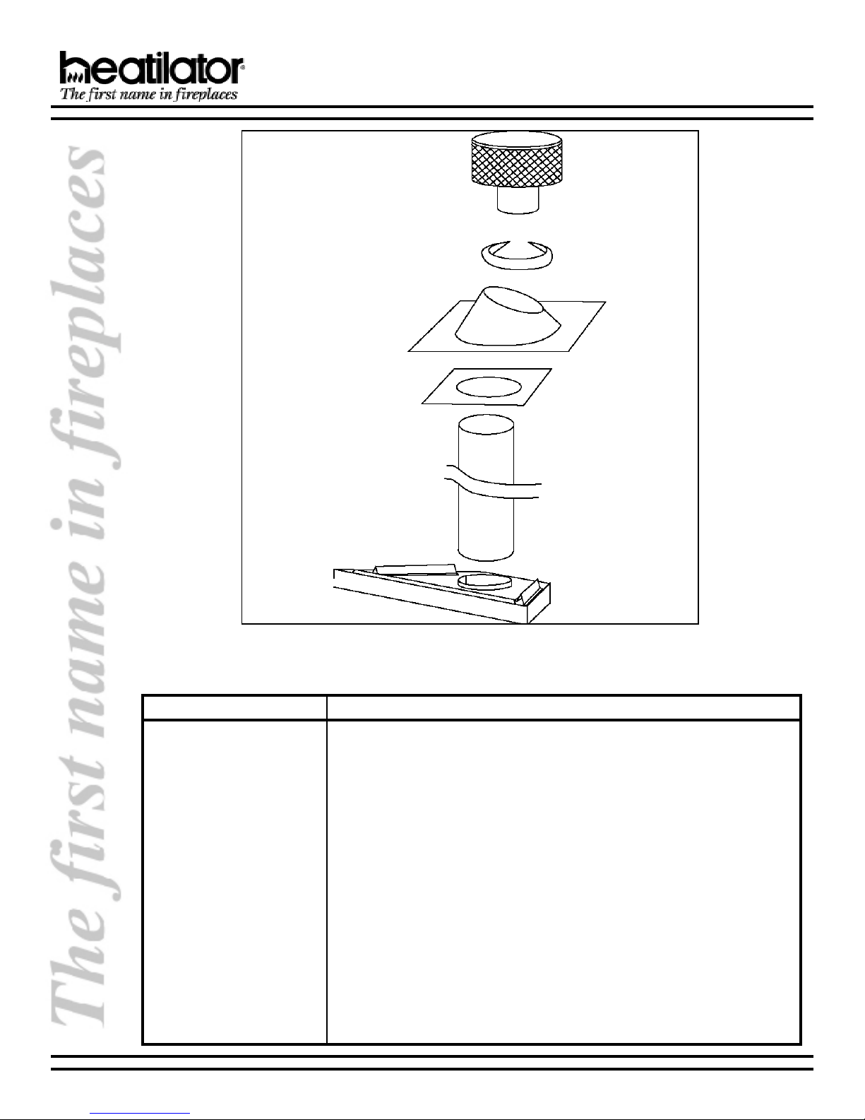
Vertical Termination Cap
Storm Collar
Roof Flashing
Firestop Spacer
5 Gas B-Vent
Pipe Section(s)
G141 SERIES B-VENT GAS APPLIANCE
The table below is a list of only those components which may be safely used with this decorative gas appliance.
Only trim kits supplied by the manufacturer shall be used in the installation of this appliance.
#golataCnoitpircseD
141Gecnailppatnaidar,tolipgnidnats,saglarutan"63
L141Gecnailppatnaidar,tolipgnidnats,sagenaporp"63
E141Gecnailppatnaidar,noitingicinortcele,saglarutan"63
EL141Gecnailppatnaidar,noitingicinortcele,sagenaporp"63
RyrotcarfeR
63GRtiKyrotcarfeR
PKCtiknoisrevnocsagenaporpotsaglarutaN
NKCtiknoisrevnocsaglarutanotsagenaporP
4CR)tolipgnidnats(lortnocetomeR
5CR)noitingicinortcele(lortnocetomeR
6CRlortnocetomeR
41KAtiKriA
6301MD)kcalB(sroodssalgdlof-iB
A6301MD)ssarBeuqitnA(sroodssalgdlof-iB
B6301MD)ssarBdehsiloP(sroodssalgdlof-iB
B2EKQdnuorruSeliT
A163FD)ssarBeuqitnA(rooDdexiF
B163FD)ssarBdehsiloP(rooDdexiF
32921 Rev A 4 10-00
G141 SERIES B-VENT GAS APPLIANCE
B. LOCATIONS & CLEARANCES
31
1
/
2
3
/
15
4
5
/
36
8
21
3
36
38
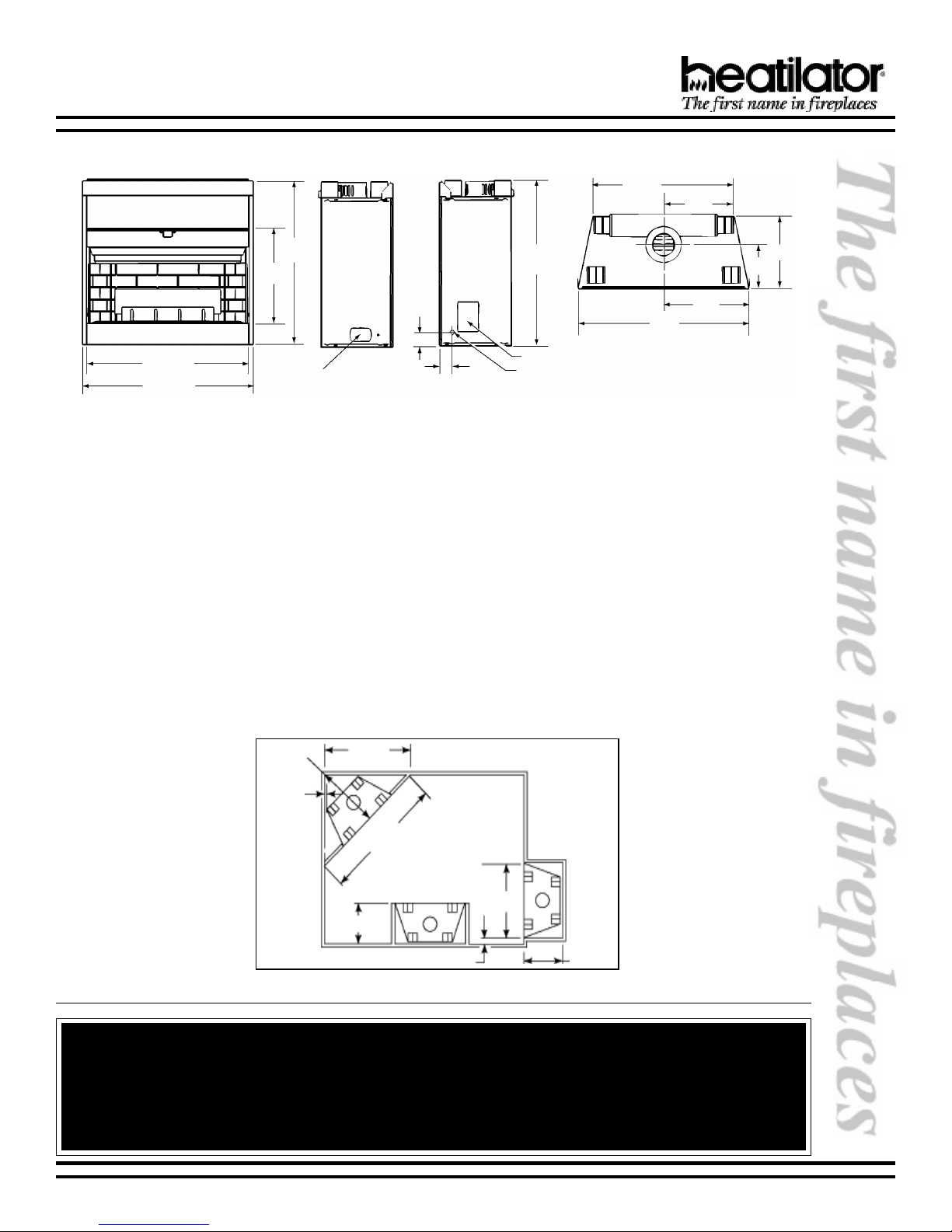
FRONT LEFT SIDE TOPRIGHT SIDE
Junction Box
FIREBOX DIMENSIONS
3
/
2
4
3
/
36
4
Air Kit
Gas Line
19
38
1. LOCATION AND SPACE REQUIREMENTS.
This appliance may be installed along a wall, across a corner or in an exterior chase. DO NOT install B-Vent
Gas Appliances in strong negative air locations, such as a basement or a public facility. This fireplace
uses room air for normal operation and could have problems establishing a positive draft in negative
air locations. In lieu, we recommend a direct vent appliance.The G141 Series may be installed at a
height level with the floor, or it can be raised up from the floor to enhance its visual impact. Figure 1 illustrates
a variety of ways the fireplace may be located in a room. These fireplaces are also certified for installation in
a bedroom or bed/sitting room in the U.S. and Canada. (Bedroom installations in Canada require the addition
of non-operable doors.)
2. CLEARANCES.
The following clearances to combustibles must be maintained: Minimum clearances to the top standoffs of the
fireplace - 0, floor - 0, back - 1, sides - 1, face of the fireplace to ceiling - 30. Minimum clearances to venting
are as follows: Horizontal run sections require a 3 minimum air space on the top and a 1 minimum air space
on the sides and bottom of the vent section. Venting that is vertical requires a 1 minimum air space completely
around the vent section.
32
1
/
2
46
16
10
1
Min.
Figure 1 - Fireplace Locations and Clearances
Before moving to the following pages, do the following:
1. Wear gloves and safety glasses for protection.
2. Keep hand tools in good condition. Sharpen cutting edges and make sure tool handles are secure.
3. Always maintain the minimum air space required to the enclosure to prevent fire.
10-00 5 32921 Rev A
65
40
17
171
WARNING!

G141 SERIES B-VENT GAS APPLIANCE
C. FRAMING
1. FRAMING THE FIREPLACE.
The G141 Series Gas Appliance will fit a framed opening of 17 deep x 40-1/4 wide x 36-3/4 tall.
Figure 2 shows a typical framing of this appliance assuming combustible materials are used. All required
clearances to combustibles around the fireplace must be adhered to. A 1 air space clearance must be
maintained at the back and sides of the firebox assembly. Any framing on top of the fireplace must be above
the top standoffs. Vent sections for a horizontal run require a 3 minimum air space clearance on top and a 1
minimum air space clearance on the sides and bottom. Vertical vent sections require a 1 minimum air space
clearance completely around the vent section.
Note: If a hand held Remote Control (RC4 or RC5)
is to be used, wiring must be done prior to finishing to avoid reconstruction.
Minimum vent
clearances are
per vent
manufacturers
specifications
3
36
1
/
40
17
Figure 2 - Framing Requirements
4
Note: The Wall Switch must be wired prior to applying the finishing material to the wall in order to avoid
reconstruction.
9 to 12 Mantel Projection: 41 height
0 to 9 Mantel Projection: 38 height
/
4
Figure 3 - Mantle Heights
Minimum allowable mantel heights are shown in
Figure 3. All required clearances must be adhered
to.
This fireplace may be placed on either a combustible
or noncombustible continuous, flat surface. If the
fireplace is installed on combustible flooring other than
wood, a metal or wood panel needs to be installed
underneath the appliance extending its full width and
depth. Slide the fireplace into position and level the
fireplace from side-to-side and front-to-back. Shim with
noncombustible material, such as sheet metal, as
necessary.
Secure the fireplace by bending out the nailing flanges
located on each side of the fireplace and nailing the
fireplace to the framing. See Figure 4.
32921 Rev A 6 10-00
D. SETTING THE FIREPLACE
Figure 4 - Nailing Flanges
G141 SERIES B-VENT GAS APPLIANCE
E. VENTING
1. TERMINATION.
Common venting of this gas appliance with other
gas appliances is not allowed.
This fireplace requires the use of a 5 B-vent pipe
for operation and must be terminated above the
roof line. Never downsize pipe. Follow all B-vent
requirements and installation instructions.
The minimum height of vent installation must be 9
from the top or 12 from the base of the appliance.
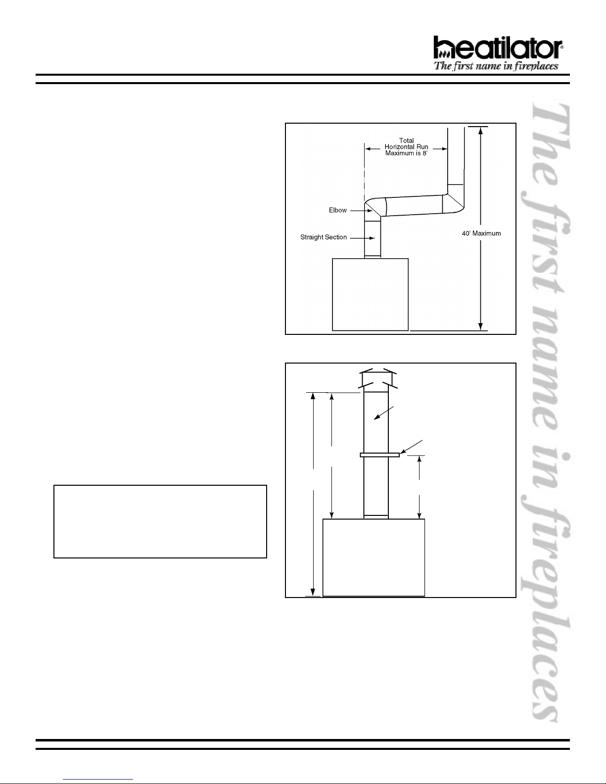
Horizontal run must never exceed 20% of the height
of the vent system as shown in Figure 5.
The Figures 5 and 6 show the maximum distances
from the base of the fireplace, as well as the
minimum air space clearances that must be
maintained during termination of this appliance.
Maximum straight unsupported rise - 25 feet;
maximum horizontal unsupported run - 3 feet; air
space clearances around vertical rise - 1 on all
sides; air space clearances around the horizontal
run - 3 on top and 1 on sides and bottom; maximum
height - 40 from the base of the fireplace.
Figure 5 - Venting Off The Top of Appliance
Note: The horizontal run of vent must have a
1/4 rise for every 1 ft. of run towards the termination. Never allow the vent to run downward.
This could cause high temperatures and may
present the possibility of a fire.
Minimum clearances are per vent
manufacturers specifications
9 Min.
40
Max.
Figure 6 - Framing Requirements
Metal plumbers strap
secured to framing
Vent supports are per
vent manufacturers
specifications
10-00 7 32921 Rev A
G141 SERIES B-VENT GAS APPLIANCE
2. ASSEMBLY.
a. Assembling Vent Sections. Attach a straight
vent section to the top of the fireplace. Elbows
directly off the top of the fireplace are not
allowed. This may cause the fireplace to
operate ineffectively. Secure the attached vent
section to the appliance with the three screws
supplied. Use only B-vent sections.
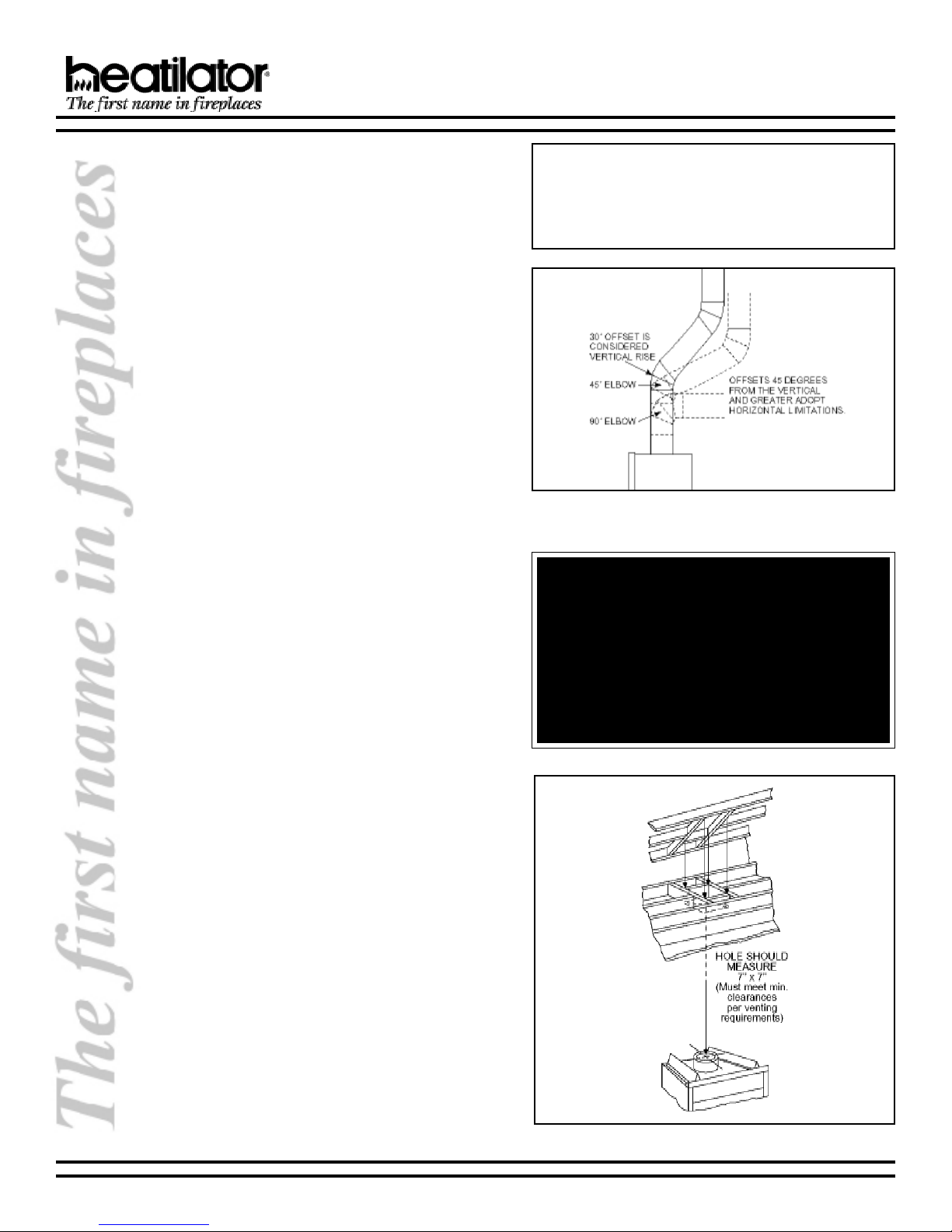
b. Using Elbows. Elbows 45 degrees and greater
from the vertical shall be considered horizontal
and therefore adopt horizontal run limitations.
See Figure 7.
c. Penetrating the Ceiling. Mark and cut out
an opening in the ceiling for the firestop spacer.
Frame the opening with the same size lumber
used in the ceiling joists.
d. Installing the Firestop Spacers. Firestop
spacers must be used whenever the venting
penetrates a ceiling/floor area.
In all situations, firestop spacers are to be
nailed to the ceiling joists from the bottom or
appliance side, EXCEPT when the space above
is an insulated ceiling or attic space. In this
situation, the firestop spacer must be nailed
from the top side to prevent loose insulation
from falling into the required one inch air space
around the vent system.
Install the firestop spacer by positioning and
nailing the four sides of the firestop spacer to
the joists using a minimum of three nails per
side.
Note: Be sure to provide intermediate support
for the vent during construction and check to
be sure inadvertent loading has not dislodged
the vent from the appliance or any vent joint.
Figure 7 - Using Elbows
WARNING!
When vent sections exceeding 3 feet
in length are installed between an offset and return, structural support must
be provided to reduce off-center loading and prevent vent sections from
separating at the vent joints. Follow all
B-vent manufacturer guidelines.
e. Securing Vent System. Continue assembling
the vent sections up through the firestop
spacers as needed. Vent sections must be
locked into position. Elbows and chimney
stabilizers have straps for securing these parts
to joists or rafters.
f. Marking the Exit Point in the Roof. Locate
the point where the venting will exit the roof by
plumbing down to the center of the vent system.
Drive a nail up through the roof to mark the
center. See Figure 8.
g. Cutting Out the Hole in the Roof. Measure
to either side of the nail and mark that 7 x 7
opening required (must meet minimum
clearances per venting requirements). This is
measured on the horizontal; actual length may
32921 Rev A 8 10-00
Figure 8 - Exiting Through the Roof
G141 SERIES B-VENT GAS APPLIANCE
be larger depending on the pitch of the roof.
Cut out and frame the opening. See the Uniform
Building Code for Roof Framing details. A one
inch minimum air space clearance must be
maintained between the vent section and the
roof.
h. Install Roof Flashing or Site-Produced
Chase Top. Position a roof flashing or a site-
produced chase to and secure into place.
i. Assembling Vent Sections. Continue to add
vent sections through the roof opening,
maintaining a minimum of one inch air space
clearance.
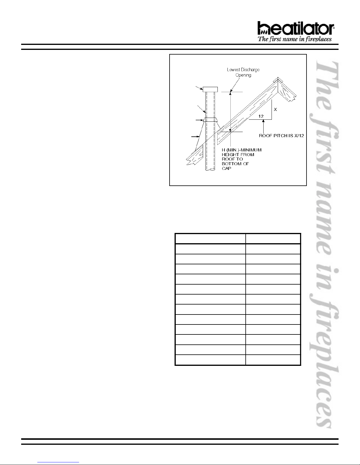
j. Termination Cap. Major building codes
specify a minimum termination height above
the roof top depending on the roof pitch. See
Figures 9 and 10.
These termination heights are necessary in the
interest of safety and do not guarantee proper
operation. Trees, buildings, adjoining roof lines,
adverse wind conditions, etc. may create a
need for a taller roof termination should down
drafting occur.
To install the termination cap, slide the cap
vent sections into the vent pipe. Secure the
cap using the screws provided.
k. Checking the Vent System. Periodically the
venting system should be tested to assure
proper operation. This can be done with a
match while the fireplace is operating.
Hold a lighted match at the top edge of the
firebox opening. If the flames and smoke remain
upright, ventilation is acceptable. If the flames
and smoke are drawn into the firebox, this
means ventilation is good. If the flames and
smoke are forced away from the firebox, this
may indicate a ventilation blockage or down
draft resulting in gas spillage into your home. If
this occurs, turn off the fireplace and do not
burn it until it has been inspected by a qualified
service person.
If you have installed optional doors, close the
doors and conduct the test following the same
instructions above. See Figure 11.
Listed
Cap
Listed
Gas
Vent
Storm
Collar
Roof
Flashing
Secured
with
Nails
Figure 9
Vent Height for Vertical Termination
hctiPfooRteef).niM(H
21/6ottalF0.1
21/7ot21/652.1
21/8ot21/7revO5.1
21/9ot21/8revO0.2
21/01ot21/9revO5.2
21/11ot21/01revO52.3
21/21ot21/11revO0.4
21/41ot21/21revO0.5
21/61ot21/41revO0.6
21/81ot21/61revO0.7
21/02ot21/81revO5.7
21/12ot21/02revO0.8
Figure 10
Minimum Termination Height
10-00 9 32921 Rev A
 Loading...