

Heatilator G136, G136L, G136LE, G136E Owner's Manual And Installation Instructions
OWNERS MANUAL AND
INSTALLATION INSTRUCTIONS
G136 SERIES GAS APPLIANCE
MODELS: G136, G136L, G136E, G136LE
FOR RESIDENTIAL USE
CAUTION:
Do not expose the appliance to the elements
(such as rain, etc.).
WARNING: If the information in this manual
is not followed exactly, a fire or explosion may
result causing property damage, personal injury or loss of life.
Do not store or use gasoline or other flammable
vapors and liquids in the vicinity of this or any
other appliance.
What to do if you smell gas
Do not try to light any appliance.
Do not touch any electrical switch; do not use
any phone in your building.
Immediately call your gas supplier from a
neighbors phone. Follow the gas suppliers
instructions.
If you cannot reach your gas supplier, call the
fire department.
Installation and service must be performed by a
qualified installer, service agency or the gas
supplier.
Improper installation, adjustment, alteration, service or maintenance can cause injury or property damage. Refer to this
manual. For assistance or additional information, consult a qualified installer, service agency or the gas supplier.
08-03 20356 Rev R 1
WARNING!

G136 SERIES INSTALLATION INSTRUCTIONS
Please retain this manual for future reference.
Table of Contents
Design and Installation Considerations for B-Vents ..................................................................................... 3
A. Appliance Specifications ............................................................................................................................. 4
B. Description of the Gas Appliance ................................................................................................................ 5
C. System Components................................................................................................................................... 7
D. Pre-Installation Preparation ......................................................................................................................... 8
E. Step-by-Step Installation ............................................................................................................................ 11
F. Operating Instructions ............................................................................................................................... 21
G. Maintenance Instructions .......................................................................................................................... 26
H. Troubleshooting ........................................................................................................................................ 28
I. Replacement Parts.................................................................................................................................... 30
J. Accessories .............................................................................................................................................. 32
Index ......................................................................................................................................................... 35
Warranty ................................................................................................................................................... 36
WARNING!
DO NOT use this appliance if any part has been under water. Immediately call a qualified service technician to
inspect the appliance, to replace any part of the control system and any gas control which has been under
water.
Safety Precautions
1. Please read these installation instructions completely before beginning installation procedures. Failure to follow them
could cause a malfunction resulting in serious injury and/or property damage.
2. Always check your local building codes prior to installation. The installation must comply with all local, regional, state
and national codes and regulations.
3. Installation and repair should be done by a qualified service person. This appliance should also be inspected annually
by a qualified service person. More frequent inspections/cleaning may be required due to excessive lint from carpeting,
bedding material, etc. It is imperative that the control compartment, burners and circulating air passageways of the
appliance be kept clean.
4. This is a vented gas appliance. Do not burn wood or other material in this appliance.
5. NEVER leave children unattended when there is a fire burning in the appliance.
6. This appliance must be vented with a minimum 5 B-Vent system and must terminate above the roof line. Venting
must not be connected to a chimney flue servicing a solid fuel burning appliance. Never downsize pipe.
7. Use only the fuel gas specified on the rating label of this gas appliance. Keep any flammable liquids a safe distance
from the appliance.
8. While servicing this appliance, always shut off all electricity and gas to the appliance. This will prevent possible
electrical shock or burns. Also, make sure the appliance is completely cooled before servicing.
9. The appliance and its manual shutoff valve must be disconnected from the gas supply piping system during any
pressure testing of that system at test pressures in excess of 1/2 psi (3.5 kPa). The appliance must be isolated from
the gas supply piping system by closing its manual shutoff valve during any pressure testing of the gas supply piping
system at test pressures equal to or less than 1/2 psi (kPa).
10. Do not use this appliance if any part has been under water. Immediately call a qualified service technician to inspect
the appliance and to replace any part of the control system and any gas control which has been under water.
11. Be sure to provide adequate clearances around the air openings into the combustion chamber and adequate
accessibility clearances for servicing and proper operation.
12. Provisions shall be made to provide adequate combustion and ventilation air.
13. The appliance area shall be kept clear and free from combustible materials, gasoline and other flammable vapors and
liquids.
14. The flow of combustion and ventilation air should not be obstructed.
2 20356 Rev R 08-03
G136 SERIES INSTALLATION INSTRUCTIONS
DESIGN AND INSTALLATION CONSIDERATIONS FOR B-VENTS
When selecting a location for your B-Vent appliance, it is important to evaluate a number of considerations. Modern
construction techniques can create conditions that may not allow your vent to draft properly. This may result in spillage
from your B-Vent appliance, as well as cause other combustion appliances to operate incorrectly.
Tightly sealed construction is important for energy efficiency. Unfortunately, a great deal of effort has been directed to
tightening up sidewall construction, while considerably less attention has been paid to tightening upper portions of the
warm air envelope (insulated ceilings). This has increased the Stack Effect, a condition that increases the negative
pressure generated by the structure. This negative pressure will directly affect the drafting performance of a B-Vent
appliance vent. To minimize the negative pressure generated by stack effect, make certain that all duct work installed in
the attic spaces is sealed airtight. Minimize the number of recessed light fixtures installed in the insulated ceiling and use
sealed recessed light fixtures. Finally, make certain the whole house fans and attic access panels are tightly sealed.
These are important design considerations that must be observed during the design and construction stage of the home.
If you desire to put an appliance in your basement, we recommend that you consider a direct vent gas appliance. Basements
always have a significant negative air pressure that causes the B-Vent system to be more susceptible to spillage and cold
flue back drafting. Since direct vent gas appliances are sealed, they are not affected by the negative pressure that exists
in basements.
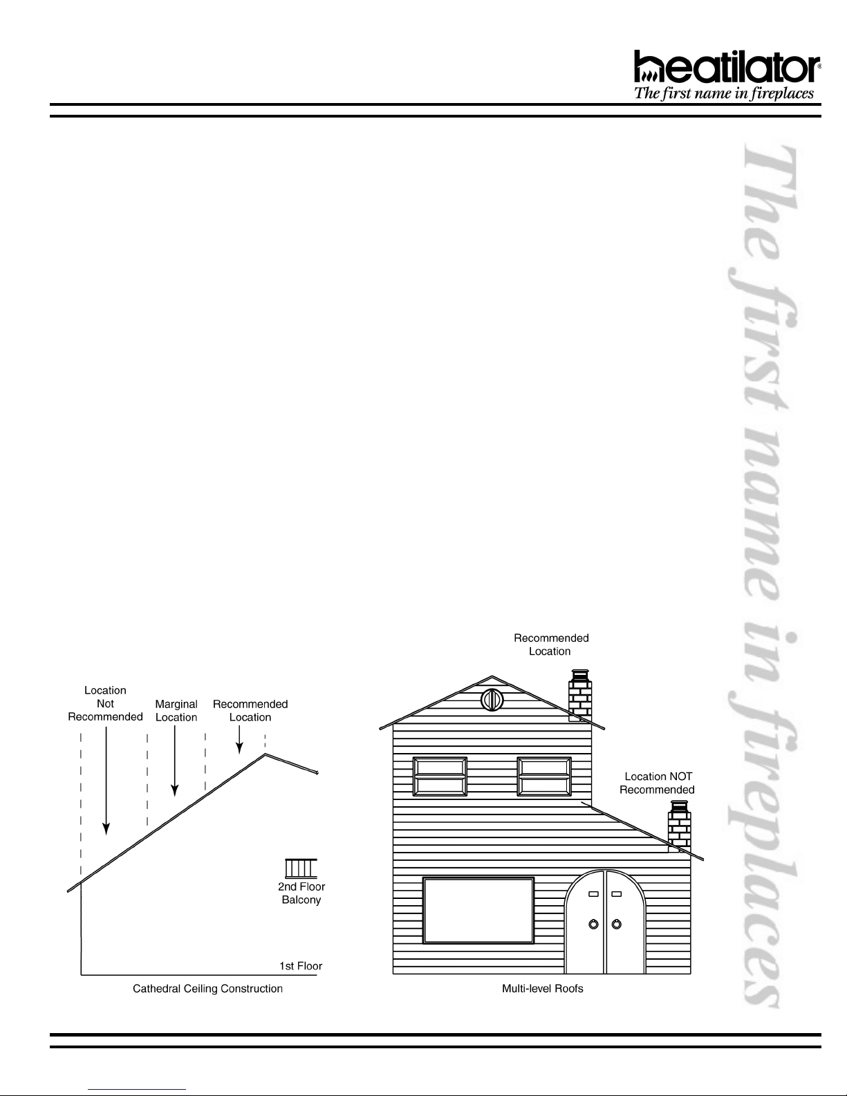
Finally, a B-Vent appliance performs best when the vent (roof termination) is located on the upper half of the roof, especially
when cathedral ceilings are present. Vents that are located on the lower half of the roof realize what is known as lazy flue
and will not draft as well as a vent that is located in the upper portion of the roof. The reason for this is that the stack effect
generated by the overall height of the living spaces inside the house will exceed the draft generated by the vent system.
If you desire to place an appliance in a location where the termination cap would be located on the lower half of a roof;
such as on an outside wall at the base of a cathedral ceiling, we recommend that you consider using a direct vent gas
appliance. This will ensure an appliance that operates correctly.
These properties do not affect just your B-Vent appliance. They can cause any woodburning fireplace as well as any
conventionally vented (B-Vent) gas appliance to operate improperly. Careful planning at this stage of your project will
ensure satisfaction with the operation of your appliance once it is completed.
08-03 20356 Rev R 3

G136 SERIES INSTALLATION INSTRUCTIONS
A. APPLIANCE SPECIFICATIONS
1. Certification
The G136 Series Vented Gas Appliance has been
tested in accordance with the standard ANSI Z21.50-
1998-CGA 2.22-M98 and has been certified by
Warnock Hersey for installation and operation as
described in these Installation and Operating
Instructions. All components are AGA or UL safety
certified.
2. Local Codes
Check with your local building code agency prior to
installing this appliance to ensure compliance with
local codes, including the need for permits and follow-
up inspections. This appliance must conform with
local codes, or in the absence of local codes, comply
with the National Fuel Gas Code, ANSI Z223.1-latest
edition in the U.S.; in Canada, the CANI-B149-latest
edition.
3. Optional Components
This gas appliance has been tested and listed for use
with the optional components listed below. Many
optional components may be purchased separately
and installed at a later date. However, installation of
a remote control or fan kit will require electrical power.
To avoid costly reconstruction, a separate course of
electrical power should be supplied to the appliance
at the time of initial installation of the system for
possible addition of these accessories at a later date.
4. Fuel
Any additions, changes or conversions required in
order for the appliance to satisfactorily meet the
application needs, must be made by a qualified
service technician using factory specified and
approved parts.
This product is manufactured to use natural gas or
propane gas, depending on model purchased. A
natural gas appliance can be converted to use
propane gas later, but only if done by a qualified
service technician and only if the CKP Natural Gas to
Propane Gas Conversion Kit is used. In the event your
appliance must be converted back to natural gas from
propane, you must use a CKN Propane Gas to Natural
Gas Conversion Kit.
If you require assistance during installation, please
contact your local dealer or contact Heatilator Technical
Services Department, Hearth & Home Technologies,
1915 W. Saunders Street, Mt. Pleasant, Iowa 52641.
HEATILATOR® is a registered trademark of Hearth &
Home Technologies, a division of HON INDUSTRIES.
WARNING!
This appliance is tested and listed for use only with the optional accessories listed in
these instructions. Use of optional accessories not specifically tested for this appliance
could void the warranty and/or result in a safety hazard.
4 20356 Rev R 08-03
G136 SERIES INSTALLATION INSTRUCTIONS
B. DESCRIPTION OF THE GAS APPLIANCE
The G136 Series is a vented gas appliance. While a significant amount of heat is created by the G136, it is not intended
to be and should not be used as a heater.
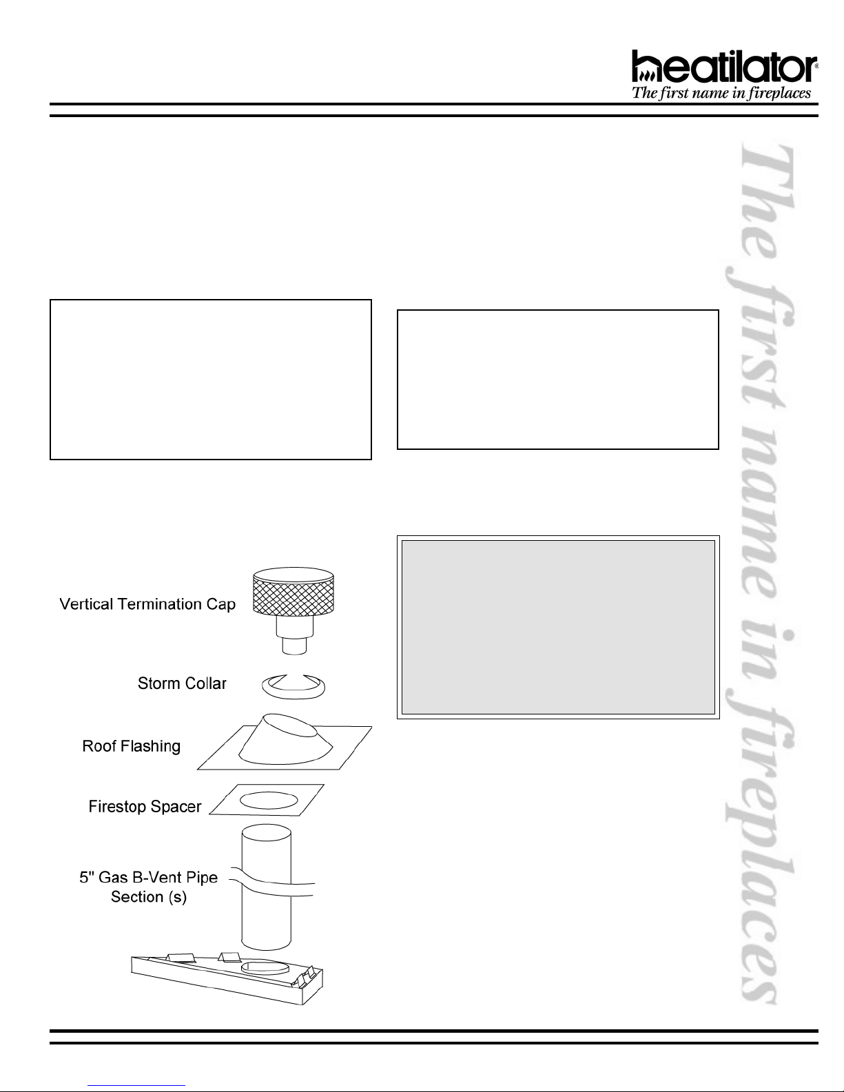
The HEATILATOR system must consist of the following:
1. Gas Appliance
2. B-Vent System
3. Termination
Tools and building supplies normally required for
installation:
Saw Wall-finishing materials
Pliers Framing material
Hammer Surround
Phillips screwdriver Caulking material
Tape measure Square
Plumb line Electric drill/bits
Level
Typical Vertical Installations
Optional components include:
1. Fan Kit
2. Remote Control
3. Outside Air Kit
4. Glass Doors
5. Rheostat Control
Note: Illustrations throughout these instructions reflect typi-
cal installations and are for design purposes only. Actual
installation may vary slightly due to individual design preferences. However, minimum and maximum clearances must
be maintained at all times.
The illustrations and diagrams used throughout these installation instructions are not drawn to scale.
We strongly recommend that you DO NOT install BVent Gas Appliances in strong negative air locations,
such as a basement or a public facility. Living rooms
with cathedral ceilings could be susceptible to a
negative air situation, but such installations can be
overcome through raising the termination,
depending on specific installations. This appliance
uses room air for normal operation and could have
problems establishing a positive draft in a negative
air location. In lieu, we recommend a Direct Vent Gas
Appliance.
08-03 20356 Rev R 5
G136 SERIES INSTALLATION INSTRUCTIONS
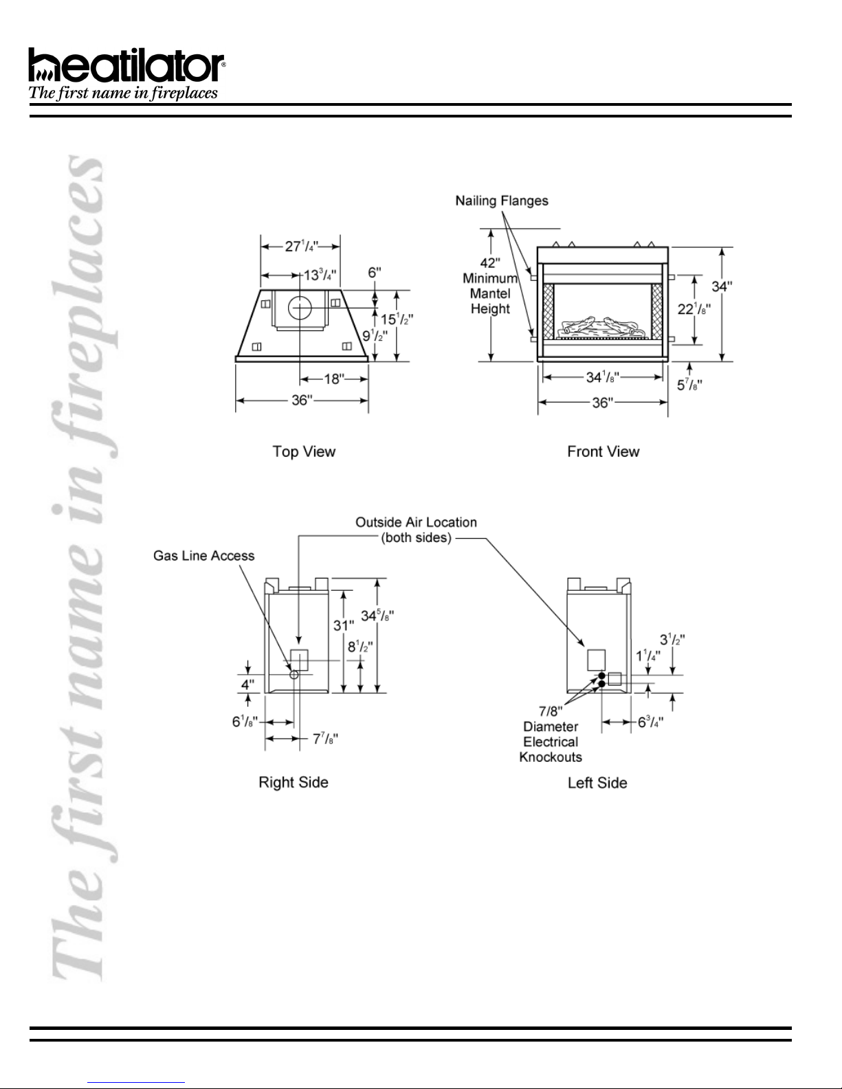
Dimensions
Framing dimensions can be found on page 9.
6 20356 Rev R 08-03

G136 SERIES INSTALLATION INSTRUCTIONS
C. SYSTEM COMPONENTS
The Table below is a list of only those components which may be safely used with this decorative gas appliance. Only trim
kits supplied by the manufacturer shall be used in the installation of this appliance.
#golataCnoitpircseD
631G .ecnailppagnitalucrictaeh,tolipgnidnats,saglarutan"63
L631G .ecnailppagnitalucrictaeh,tolipgnidnats,sagenaporp"63
E631G .ecnailppagnitalucrictaeh,noitingicinortcele,saglarutan"63
EL631G ecnailppagnitalucrictaeh,noitingicinortcele,sagenaporp"63
PKCehtgnisusagenaporpotdetrevnocebyamsledomsaglarutan(
.)tiKnoisrevnoC
41KAtiKriAedistuO
01CB.detnuomllaw,lortnoctatsoehrrotomnaF
11CB.lortnocnafdetavitca-erutarepmeT
*LTH-TRAMS-CRlortnocetomeR
*LTH-TLM-TCR
*LTH-TATS-TRAMS .remit,.pmettatsomreht,.pmetmoor,FFO/NO:etomerlanoitcnufitluM
*LTH-TTAB-TRAMS .remit,.pmettatsomreht,FFO/NO:etomerlanoitcnufitluM
PKC.tiknoisrevnocsagenaporpotsaglarutaN
NKC.tiknoisrevnocsaglarutanotsagenaporP
91KF)dedulcnilenapsseccalortnocellirgkcalb(tiKnaF
6361MD.sroodssalgmirtkcalbdlof-ibelytslanigirO
B6361MD.sroodssalgmirtssarbdehsilopdlof-ibelytslanigirO
B631FD.sroodssalgssarbdehsilopdlof-ibdexiF
)ylnotolipgnidnats(deeps
naf,.pmetmoor,lortnocemalfwol/hgih,FFO/NO:etomeRlanoitcnufitluM
.sdeenruoyotelbacilppasietomerhcihwenimretedoterutaretilotrefeR*
08-03 20356 Rev R 7

G136 SERIES INSTALLATION INSTRUCTIONS
D. PRE-INSTALLATION PREPARATION
Installation and repair should be done by a qualified service person. The appliance should be inspected before use
and at least annually by a qualified service person. More frequent cleaning may be required due to excessive lint from
carpeting, bedding material, etc. It is imperative that control compartments, burners and circulating air passageways of
the appliance be kept clean.
Due to high temperatures, the appliance should be located out of traffic and away from furniture and draperies.
WARNING!
This appliance may use the B-Vent chimney system only and must not be connected to a chimney flue servicing
a separate solid fuel burning appliance.
1. Gas Pressure
For natural gas, the minimum inlet gas supply
pressure is 4.5 inches water column, and the
maximum inlet gas pressure is 7.0 inches water
column, for the purpose of input adjustment. Input rate
is 25,000 BTU/hr. For propane gas, the inlet gas supply
pressure must be at least 11.0 inches water column and
a maximum 14.0 inches water column.
Pressure taps are provided on the gas control valve,
near the outlet to the main burner immediately
upstream of the gas supply connection to the
appliance, accessible for a test gage connection.
Optimum manifold pressure is 3.5 inches water column
for natural gas, and 10.0 inches water column for
propane gas.
2. High Altitude Installation
a. U.S. Installation
Appliances are tested and approved for elevations
from 0-2000 feet.
When installing this appliance at an elevation above
2000 feet, United States codes require a decrease
of the input rating by changing the existing burner
orifice.
Input should be reduced 4% for each 1000 feet
above sea level. Check with the local gas utility for
proper orifice size identification. This appliance
uses a .096 in./2.44 mm. orifice size on natural gas
versions and a .059 in./1.49 mm. orifice size on
propane gas versions.
Consult your local gas company for assistance in
determining the proper orifice for your location or
refer to ANSI Z223.1-latest edition, Appendix F.
b. Canadian Installation
Appliances are certified for elevations from 0-4500
feet. When installing this appliance at an elevation
between 0-4500 feet in Canada, the input rating does
not need to be reduced.
When installing this appliance at an elevation above
4500 feet in Canada, check with local authorities.
Consult your local gas company for assistance in
determining the proper orifice for you location or refer
to ANSI Z23.1-latest edition, Appendix F.
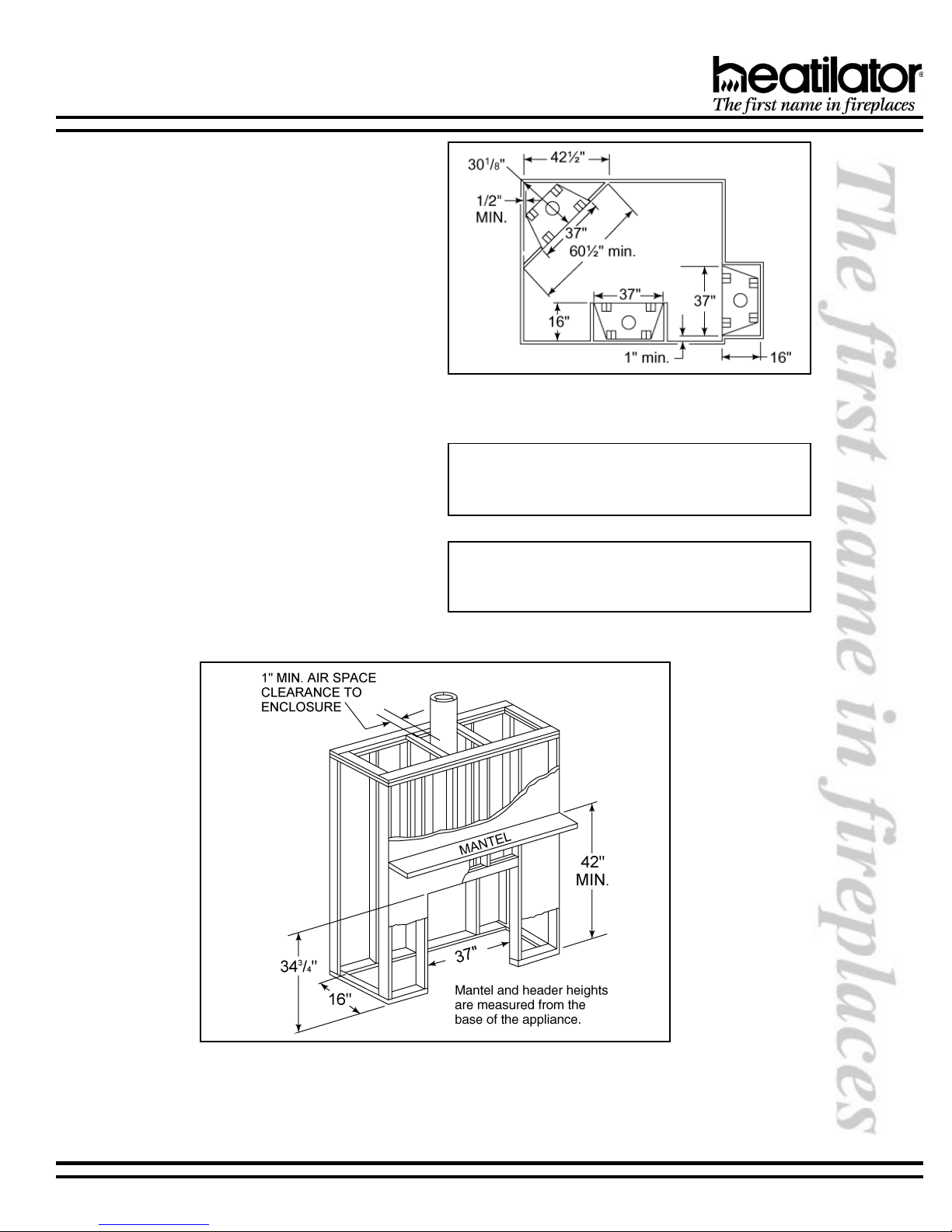
3. Location and Space Requirements
This appliance may be installed along a wall, across a
corner or in an exterior chase. This appliance must be
installed so that the draft hood is in the same
atmospheric pressure zone as the combustion air inlet
and the appliance shall be located so that the relief
opening is accessible for checking vent operation. The
G136 Series may be installed at a height level with the
floor, or it can be raised up from the floor to enhance
its visual impact. Figure 1 illustrates a variety of ways
the appliance may be located in a room. These
appliances are also certified for installation in a
bedroom or bed/sitting room in the U.S. and Canada
(bedroom installations in Canada require the addition
of non-operable doors), provided that the bedroom or
bed/sitting room has a volume of at least 1,250 cubic
feet.
WARNING!
To prevent contact with sagging or loose insulation, the appliance must not be installed
against vapor barriers or exposed insulation.
8 20356 Rev R 08-03
G136 SERIES INSTALLATION INSTRUCTIONS
4. Clearances
The following clearances to combustibles must be
maintained: Minimum clearances to the top standoffs
of the appliance - 0, floor - 0, back - ½, sides - ½,
face of the appliance to ceiling - 30. Minimum
clearances to venting are as follows: Horizontal run
sections require a 3 minimum air space on the top
and a 1 minimum air space on the sides and bottom
of the vent section. Venting that is vertical requires a
1 minimum air space completely around the vent
section. See Figure 1.
5. Framing the Gas Appliance
The G136 Series Gas Appliance will fit a framed
opening of 37 w x 16 d x 34-3/4 h.
Figure 2 shows a typical framing of this appliance
assuming combustible materials are used. All
required clearances to combustibles around the
appliance must be adhered to. A 1/2 air space
clearance must be maintained at the back and sides
of the appliance. Any framing on top of the appliance
must be above the top standoffs. Vent sections for a
horizontal run require a 3 minimum air space
clearance on top and a 1 minimum air space
clearance on the sides and bottom. Vertical vent
sections require a 1 minimum air space clearance
completely around the vent section.
Figure 1
Appliance Locations and Clearances
Note: If an optional fan kit or hand held remote control
are to be used, wiring must be done prior to finishing to
avoid reconstruction.
Note: The remote wall switch must be wired prior to ap-
plying the finishing material to the wall in order to avoid
reconstruction.
08-03 20356 Rev R 9
Figure 2 - Framing Requirements
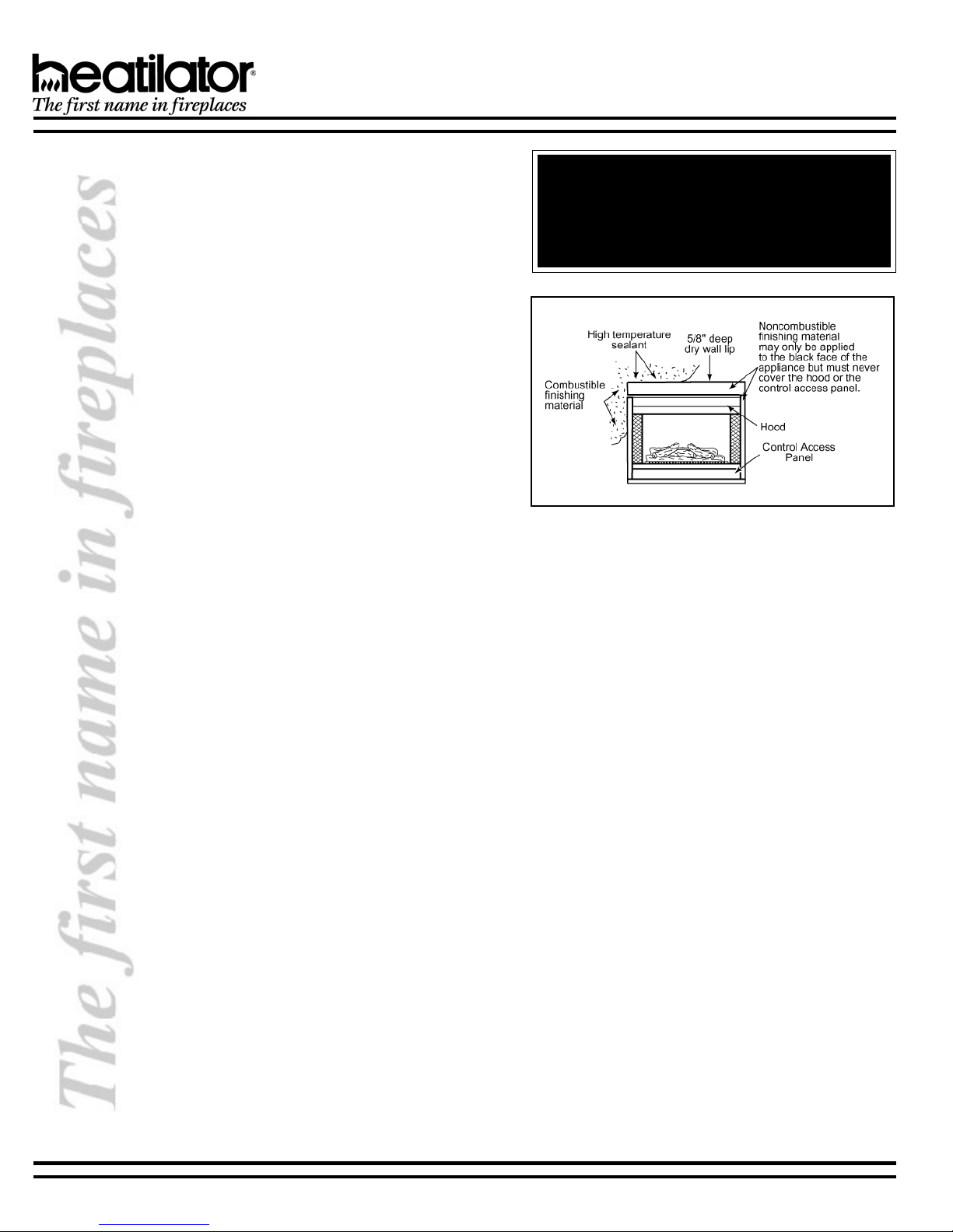
6. Finishing Materials
Only noncombustible materials may be used to cover
the black surface of the appliance front.
a. Combustible Materials
Material made of or surfaced with wood,
compressed paper, plant fibers, plastics, or any
material capable of igniting and burning, whether
flame proofed or not, plastered or unplastered.
b. Noncombustible Material
Material which will not ignite and burn. Such
materials are those consisting entirely of steel,
iron, brick, tile, concrete, slate, glass or plasters,
or a combination of the materials.
c. High Temperature Sealant Material
Sealants that will withstand high temperatures;
General Electric RTV103 Black) or equivalent,
Rutland, Inc. Fireplace Mortar #63 or equivalent.
After completing the framing and applying the
facing material (dry wall) over the framing, a
noncombustible sealant, one-half inch wide
maximum, must be used to close off any gaps at
the top and sides between the appliance and
facing to prevent cold air leaks. See Figure 3.
G136 SERIES INSTALLATION INSTRUCTIONS
WARNING!
Hood and control access panel on this appliance
cannot, in any way, be covered as it may create
a fire hazard. Draft relief openings must not be
covered or blocked.
Figure 3 - Finishing Materials
10 20356 Rev R 08-03
G136 SERIES INSTALLATION INSTRUCTIONS
E. STEP-BY-STEP INSTALLATION
WARNING!
Before starting, do the following:
1. Wear gloves and safety glasses for protection.
2. Keep hand tools in good condition. Sharpen cutting edges and make sure tool handles are secure.
3. Always maintain the minimum air space required to the enclosure to prevent fire.
1. Positioning the Gas Appliance
This appliance may be placed on either a combustible
or noncombustible continuous, flat surface. If the appliance is installed on combustible flooring other than wood,
a metal panel needs to be installed underneath the appliance extending its full width and depth. Slide the appliance into position and level from side-to-side and frontto-back. Shim with noncombustible material, such as
sheet metal, as necessary.
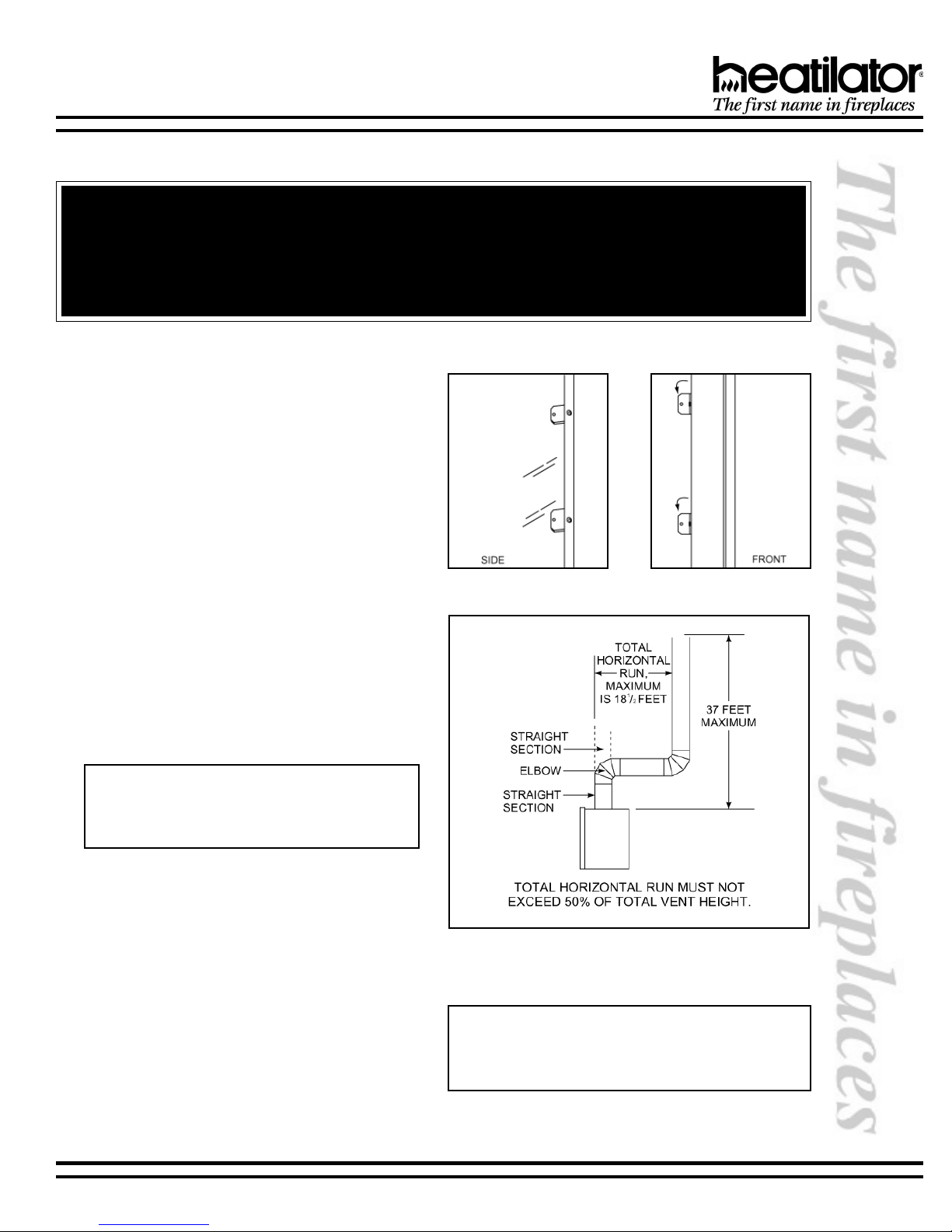
Secure the appliance by bending out the nailing
flanges located on each side of the appliance and
nailing the appliance to the framing. See Figure 4.
2. Termination
Common venting of this gas appliance with other gas
appliances is not allowed in multifamily dwellings.
Possible problems which may occur from common
venting are usually more costly and does not prevent
possible spillage of flue gas products into other
occupied spaces sharing the common vent. Noise is
easily transmitted from one area to another if common
venting is used.
Figure 4 - Nailing Flanges
Note: This appliance requires the use of a 5 B-
vent for operation and must be terminated above
the roof line. Never downsize pipe. Follow all Bvent requirements and installation instructions.
The minimum height of vent installation must be 9 from
the top or 12 from the base of the appliance. Horizontal
run must never exceed 50% of the height of the vent
system as shown in Figure 5.
The following figures are the maximum distances
from the base of the appliance, as well as the
minimum air space clearances that must be
maintained during termination of this appliance.
Maximum straight unsupported rise - 25 feet;
maximum horizontal unsupported run - 3 feet; air
space clearances around vertical rise - 1 on all sides;
air space clearances around the horizontal run - 3
on top and 1 on sides and bottom; maximum
height-40 from the base of the appliance. Every 1
of horizontal run requires at least 2 of vertical rise.
08-03 20356 Rev R 11
Figure 5
Venting Off The Top of Appliance
Note: The horizontal run of vent must have a 1/4 rise for
every 1 ft. of run towards the termination. Never allow the
vent to run downward. This could cause high temperatures and may present the possibility of a fire.
 Loading...