

Heatilator EDV3633, EDV3633I, EDV3633IL Owner's Manual
Heatilator • Eclipse • 4049-229 Rev I • 08/09 1
Model(s):
EDV3633, EDV3633I, EDV3633IL
Direct Vent Gas Appliance
Owner’s Manual
Installation and Operation
Installation and service of this appliance should be performed
by qualified personnel. Hearth & Home Technologies
suggests NFI certied or factory-trained professionals, or
technicians supervised by an NFI certied professional.
If the information in these instructions is not followed exactly, a
re may result causing property
damage, personal injury, or death.
• Do not store or use gasoline or other am
mable vapors and liquids in the vicinity of
this or any other appliance.
• What to do if you smell gas:
- Do
not try to light any appliance.
- Do not touch any electrical switch. Do not
use any phone in your building.
- Immediately call your gas supplier from
a neighbor’s phone. Follow the gas
supplier’s instructions.
- If you cannot reach your gas supplier, call
the re department.
• Installation and service must be performed
by a qualied installer, service agency, or
the gas supplier.
WARNING
This appliance may be installed as an OEM installation
in manufactured home (USA only) or mobile home and
must be installed in accordance with the manufacturer’s
instructions and the manufactured home construction and
safety standard, Title 24 CFR, Part 3280 or Standard for
Installation in Mobile Homes, CAN/CSA Z240MH.
This appliance is only for use with the type(s) of gas
indicated on the rating plate.
DO NOT DISCARD THIS MANUAL
CAUTION
• Important operating and
maintenance instructions
included.
•
Leave this manual with
party responsible for
use and operation.
•
Read, understand and follow
these instructions for safe
installation and operation.
DO
N
OT
D
IS
CARD
In the Commonwealth of Massachusetts installation must
be performed by a licensed plumber or gas tter;
See Table of Contents for location of additional
Commonwealth of Massachusetts requirements.
HOT SURFACES!
Glass and other surfaces are hot during
operation and cool down.
WARNING
• CAREFULLY SUPERVISE children in same room as
appliance.
• Ale rt chi ld r en an d a du lts to ha za rds of h i gh
temperatures.
High temperatures may ignite clothing or other
ammable materials.
• Keep clothing, furniture, draperies and other combustibles
away.
Hot glass will cause burns.
• Do not touch glass until it is cooled
• NEVER allow children to touch glass
• Keep children away
This appliance has been supplied with an integral
barrier to prevent direct contact with the xed glass
panel. Do NOT operate the appliance with the barrier
removed.
Contact your dealer or Hearth & Home Technologies if the
barrier is not present or help is needed to properly install one.

Heatilator • Eclipse • 4049-229 Rev I • 08/092
Listing Label Information/Location
Model Name: ___________________________________________ Date purchased/installed: __________________
Serial Number: __________________________________________ Location on replace: _____________________
Dealership purchased from: _______________________________ Dealer Phone: __________________________
Notes: _______________________________________________________________________________________
_____________________________________________________________________________________________
A. Congratulations
Congratulations on selecting a Heatilator gas replace, an
elegant and clean alternative to wood burning replaces.
The Heatilator gas replace you have selected is designed
to provide the utmost in safety, reliability, and efciency.
As the owner of a new replace, you’ll want to read and
carefully follow all of the instructions contained in this
owner’s manual. Pay special attention to all cautions and
warnings.
This owner’s manual should be retained for future reference.
We suggest that you keep it with your other important
documents and product manuals.
The information contained in this owner’s manual, unless
noted otherwise, applies to all models and gas control
systems.
Your new Heatilator gas replace will give you years of
durable use and trouble-free enjoyment. Welcome to the
Heatilator family of replace products!
We recommend that you record the following pertinent
information about your replace.
The model information regarding your specic replace can be found on
the rating plate usually located in the control area of the replace.
Homeowner Reference Information
Read this manual before installing or operating this appliance.
Please retain this owner’s manual for future reference.
XXXX
CERTIFIED
FOR CANADA
CERTIFIÉ POUR LE
CANADA
Hearth & Home Technologies Inc
1915 W. Saunders Street
Mt. Pleasant, IA 52641
SERIAL
NO. DE SÉRIE
ANSI Standard
MODEL MFG. DATE
MODÈLE DATE DE FAB.
GAS TYPE/TYPE DE GAZ NATURAL/NATUREL PROPANE
ALTITUDE 0-2000 2000-4000 FT/PI 0-2000 2000-4000 FT/PI
MAX INPUT/DÉBIT XX,XXX XX,XXX BTUH XX,XXX XX,XXX BTUH
MIN INPUT/DÉBIT XX,XXX XX,XXX BTUH XX,XXX XX,XXX BTUH
MANIFOLD PRESSURE/PRESSION TUBULAIRE
MAX. XX IN. W.C./C. D'EAU XX IN. W.C./C. D'EAU
MIN. XX IN. W.C./C. D'EAU XX IN. W.C./C. D'EAU
MIN. INLET PRESS. XX IN. W.C./C. D'EAU 1XX IN. W.C./C. D'EAU
FOR THE PURPOSE OF INPUT ADJUSTMENT
PRESS. MIN. D'ALIMENTATION
ORIFICE SIZE
DIAM. DE L'INJECTEUR XX/XX DIA. in./mm XX/XX DIA. in./mm
LESS THAN/MOINS DE 3 AMPÈRES., 115V., 60 Hz
DO NOT REMOVE OR COVER THIS LABEL.
VENTED GAS FIREPLACE - NOT FOR USE WITH SOLID FUEL.
FOYER À GAZ À ÉVACUATION - NE DOIT PAS ÊTRE UTILISÉ
AVEC UN COMBUSTIBLE SOLIDE.
XXXXXXXXX
XXXXXX
Serial #
Gas Type
Orifice
Size
Model #

Heatilator • Eclipse • 4049-229 Rev I • 08/09 3
Safety Alert Key:
• DANGER! Indicates a hazardous situation which, if not avoided will result in death or serious injury.
• WARNING! Indicates a hazardous situation which, if not avoided could result in death or serious injury.
• CAUTION! Indicates a hazardous situation which, if not avoided, could result in minor or moderate injury.
• NOTICE: Used to address practices not related to personal injury.
Table of Contents
A. Congratulations 2
B. Warranty
5
1 Listing and Code Approvals
A. Appliance Certication 7
B. Tempered Glass Specications
7
C. BTU Specications
7
D. High Altitude Installations
7
E. Non-Combustible Materials Specication
7
F. Combustible Materials Specication
7
G. Electrical Codes
7
H. Requirements for
the Commonwealth of Massachusetts
8
User Guide
2 Operating Instructions
A. Gas Fireplace Safety 9
B. Your Fireplace
9
C. Fan Kit 1
0
D. Clear Space 1
0
E. Fixed Glass Assembly 1
0
F. Remote Controls, Wall Controls and
Wall Switches 1
0
G. Before Lighting Fireplace 1
0
H. Lighting Instructions (IPI) 1
1
I. Lighting Instructions (Standing Pilot) 1
2
J. After Fireplace is Lit 1
3
K. Flame Adjustment Control 1
3
L. Frequently Asked Questions 1
3
3 Maintenance and Service
A. Maintenance Tasks-Homeowner 14
B. Maintenance Tasks-Qualied Service Technician 1
5
Installer Guide
4 Getting Started
A. Typical Appliance System 17
B. Design and Installation Considerations 1
8
C. Tools and Supplies Needed 1
8
D. Inspect Appliance and Components 1
8
5 Framing and Clearances
A. Selecting Appliance Location 19
B. Constructing the Appliance Chase 2
0
C. Clearances 2
0
D. Mantel and Wall Projections 2
1
6 Termination Locations
A. Vent Termination Minimum Clearances 22
7 Vent Information and Diagrams
A. Approved Pipe 24
B. Vent Table Key 2
4
C. Use of Elbows 2
4
D. Measuring Standards 2
4
E. Vent Diagrams 2
5
8 Vent Clearances and Framing
A. Pipe Clearances to Combustibles 30
B. Wall Penetration Framing 3
0
C. Install the Ceiling Firestop 3
1
D. Install Attic Insulation Shield 3
2
9 Appliance Preparation
A. Securing and Leveling the Appliance 33
10 Installing SLP Vent Pipe
A. Assemble Vent Sections 34
B. Assemble Slip Sections 3
4
C. Securing the Vent Sections 3
5
D. Disassemble Vent Sections 3
5
E. Installing Metal Roof Flashing 3
6
F. Installing Vertical Termination Cap 3
7
G. Assemble and Install Storm Collar 3
7
H. Install Heat Shields and
Horizontal Termination Cap 3
8
11 Shrouds
A. HHT Shrouds 40
B. Field Constructed Shrouds 4
0
12 Gas Information
A. Fuel Conversion 42
B. Gas Pressure 4
2
C. Gas Connection 4
2
D. High Altitude Installations 4
2
13 Electrical Information
A. Wiring Requirements 43
B. Standing Pilot Ignition System Wiring 4
3
C. Intellire Ignition System Wiring 4
3
D. Optional Accessories Requirements 4
3
E. Electrical Service and Repair 4
4
F. Junction Box Installation 4
5
G. Wall Switch Installation for Fan (Optional) 4
5

Heatilator • Eclipse • 4049-229 Rev I • 08/094
= Contains updated information.
14 Finishing
A. Mantel and Wall Projections 46
B. Facing Material 4
6
15 Appliance Setup
A. Remove Packaging Materials 47
B. Remove Glass Assembly 4
7
C. Logs 4
7
D. Place Lava Rock, Rockwool 4
7
E. Replace Glass 4
8
F. Install Floor Cover 4
8
G. Grilles and Screen 4
8
H. Air Shutter Setting 4
9
I. Accessories 4
9
16 Troubleshooting
A. Standing Pilot Ignition System 50
B. Intellire Ignition System 5
2
17 Reference Materials
A. Appliance Dimension Diagram 54
B. Vent Components Diagrams 5
5
C. Service Parts 5
8
D. Optional Components 6
1
E. Contact Information 6
4
Heatilator • Eclipse • 4049-229 Rev I • 08/09 5
B. Warranty
Hearth & Home Technologies LIMITED WARRANTY
Hearth & Home Technologies (“HHT”) and its respective brands extends the following warranty for HHT gas, wood, pellet
and electric appliances purchased from an authorized HHT dealer and installed in the United States of America or
Canada. Warranty starts with date of purchase by the original owner (End User) except as noted for replacement parts.
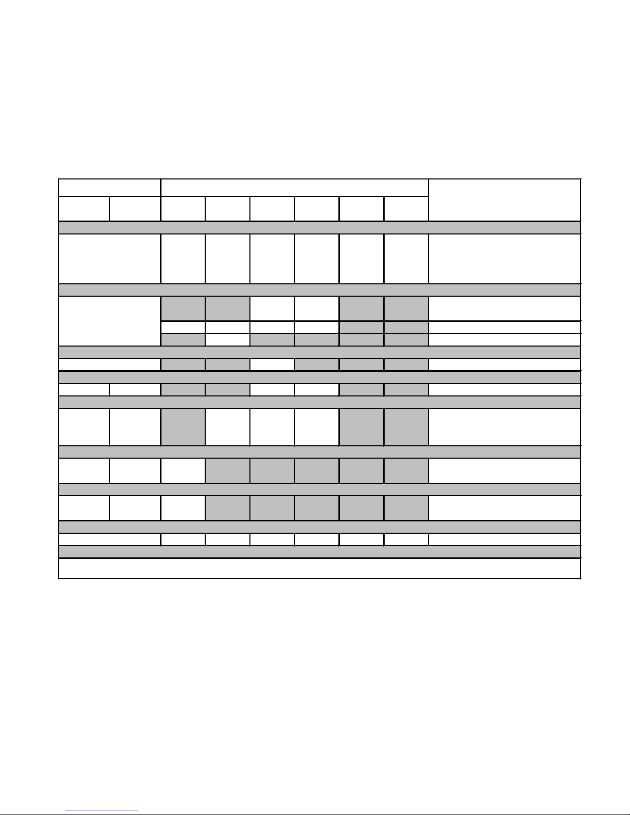
Parts Labor Gas Wood Pellet
EPA
Wood
Electric Venting
X X X X X X
All Parts and Material Except as
covered by Conditions,
Exclusion, and Limitations listed
X X
Igniters, Electronic Components,
and Glass
X X X X Blowers
X Molded Refractory Panels
X Firepots
5 years 3 years X X Castings & Baffles
7 years 3 years X X X
Firebox, HHT Chimney,
Termination & Heat
Exchanger
10
years
1 year X Burners, Logs & Refractory
Limited
Lifetime
1 year X Firebox & Heat Exchanger
X X X X X X All Replacement Parts
Warranty Period
HHT Manufactured Appliances and Venting
1 Year
Components Covered
3 years
2 years
90 Days
See Conditions, Exclusions, and limitations. 9-01-08
CONDITIONS, EXCLUSIONS & LIMITATION OF LIABILITY
• This warranty applies to the original owner and is transferable up to two years from date of purchase to the new
homeowner, provided the purchase was made through an authorized dealer or distributor of HHT, and the appliance
remains in its original place of installation.
• The maximum amount recoverable under this warranty is limited to the purchase price of the product.
• In no event shall HHT be liable for any incidental or consequential damages caused by defects in the product.
• Adjustments, regular maintenance, cleaning and temporary repairs, or the failure to duplicate the problem in the home
is not covered under this warranty.
4021-645A 09-01-08 Page 1 of 2

Heatilator • Eclipse • 4049-229 Rev I • 08/096
B. Warranty (continued)
This limited warranty does not extend to or include surface finish on the appliance or terminations, door gasketing, glass
gasketing, glass discoloration, firebrick, pellet logs, kaowool or other ceramic insulating materials. Rust and/or corrosion
on any of the metal surfaces, cast iron components, baffles, firepots, doors, or firebox area are not covered by this
warranty.
• Noise resulting from minor expansion, contraction, or movement of certain parts is normal and complaints related to
this noise are not covered by this warranty.
• HHT’s obligation under this warranty does not extend to damages resulting from: (1) installation, operation or maintenance of the appliance not in accordance with the installation instructions; operating instructions and the listing agent
identification label furnished with the appliance; (2) installation which does not comply with local building codes; (3)
shipping, improper handling, improper operation, abuse, misuse, accident or unworkmanlike repairs; (4) environmental conditions, inadequate ventilation or drafting caused by tight sealing construction of the structure or handling
devices such as exhaust fans or forced air furnaces or other such causes; (5) use of fuels other than those specified
in the operating instructions; (6) installation or use of components not supplied with the appliance or any other components not expressly authorized and approved by HHT; and/or (7) modification of the appliance not expressly authorized and approved by HHT in writing.
• This warranty does not apply to non-HHT venting components, hearth components or other accessories used in
conjunction with the installation of this product.
• This warranty is void if the appliance has been over-fired or operated in atmospheres contaminated by chlorine,
fluorine, or other damaging chemicals the appliance is subject to prolonged periods of dampness or condensation, or
there is any damage to the appliance or other components due to water or weather damage which is the result of, but
not limited to, improper chimney or venting installation.
• HHT’s liability under this warranty is limited to the replacement and repair of defective components or workmanship
during the applicable period. HHT may fully discharge all of its obligations under such warranties by repairing the
defective component(s) at HHT’s discretion. Shipping costs are not covered under this warranty.
• Some states do not allow exclusions or limitation of incidental or consequential damages, so those limitations may not
apply to you. This warranty gives you specific rights; you may also have other rights, which vary from state to state.
• EXCEPT TO THE EXTENT PROVIDED BY LAW, HHT MAKES NO EXPRESS WARRANTIES OTHER THAN THE
WARRANTY SPECIFIED HEREIN. THE DURATION OF ANY IMPLIED WARRANTY IS LIMITED TO DURATION OF
THE WARRANTY SPECIFIED ABOVE.
This Limited Warranty is effective on all HHT appliances sold after September 01, 2008 and supersedes any and all
warranties currently in existence.
If warranty service is needed, you should contact your installing dealer. If the installing dealer is unable to provide necessary parts or components, contact the nearest authorized HHT dealer or supplier.
4021-645A 09-01-08 Page 2 of 2
Heatilator • Eclipse • 4049-229 Rev I • 08/09 7
B. Tempered Glass Specications
Hearth & Home Technologies appliances manufactured
with tempered glass may be installed in hazardous
locations such as bathtub enclosures as dened by the
Consumer Product Safety Commission (CPSC). The
tempered glass has been tested and certied to the
requirements of ANSI Z97.1 and CPSC 16 CFR 1202
(Safety Glazing Certication Council SGCC# 1595 and
1597. Architectural Testing, Inc. Reports 02-31919.01 and
02-31917.01).
This statement is in compliance with CPSC 16 CFR
Section 1201.5 “Certication and labeling requirements”
which refers to 15 U.S. Code (USC) 2063 stating “…Such
certicate shall accompany the product or shall otherwise
be furnished to any distributor or retailer to whom the
product is delivered.”
Some local building codes require the use of tempered
glass with permanent marking in such locations. Glass
meeting this requirement is available from the factory.
Please contact your dealer or distributor to order.
C. BTU Specications
MODELS: EDV3633, EDV3633I, EDV3633IL
LABORATORY: Underwriters Laboratories, Inc. (UL)
TYPE: Vented Gas Fireplace
STANDARD: ANSI Z21.88b-2008•CSA 2.33b-2008
E. Non-Combustible Materials Specication
Material which will not ignite and burn. Such materials are
those consisting entirely of steel, iron, brick, tile, concrete,
slate, glass or plasters, or any combination thereof.
Materials that are reported as passing ASTM E 136,
Standard Test Method for Behavior of Materials in a
Vertical Tube Furnace at 750 ºC and UL763 shall be
considered non-combustible materials.
F. Combustible Materials Specication
Materials made of or surfaced with wood, compressed
paper, plant bers, plastics, or other material that can ignite and burn, whether ame proofed or not, or plastered
or unplastered shall be considered combustible materials.
NOT INTENDED FOR USE AS A PRIMARY HEAT SOURCE.
This appliance is tested and approved as either supplemental
room heat or as a decorative appliance. It should not be factored as primary heat in residential heating calculations.
D. High Altitude Installations
NOTICE: If the heating value of the gas has been reduced,
these rules do not apply. Check with your local gas utility or
authorities having jurisdiction.
When installing above 2000 feet elevation:
• In the USA: Reduce input rate 4% for each 1000 feet
above 2000 feet.
• In CANADA: Reduce input rate 10% for elevations
between 2000 feet and 4500 feet. Above 4500 feet,
consult local gas utility.
Check with your local gas utility to determine proper
orice size.
1
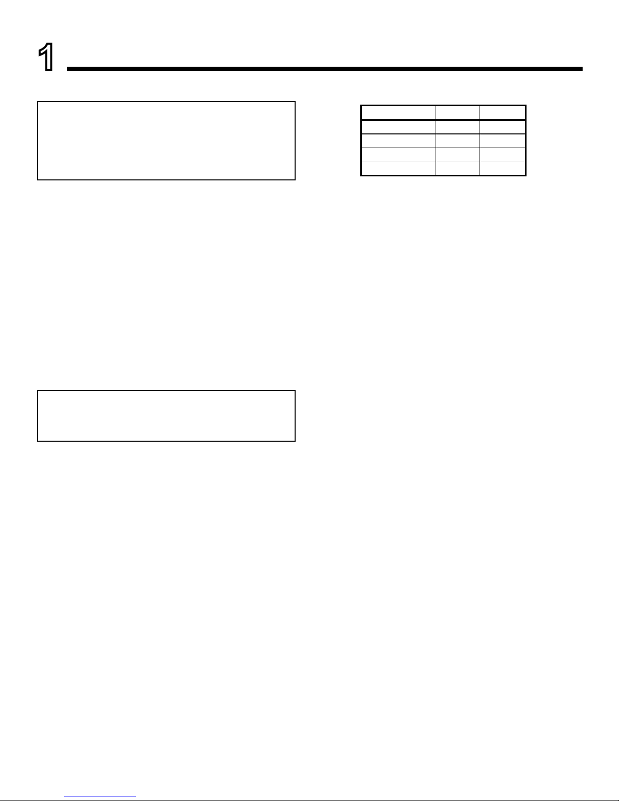
Listing and Code Approvals
A. Appliance Certication
EDV3633 Series SP IPI
Input Rate (NG) 20,000 20,000
Orice Size (NG) 0.083 0.083
Input Rate (LP) 20,000 20,000
Orice Size (LP) 0.053 0.053
G. Electrical Codes
NOTICE: This appliance must be electrically wired
and grounded in accordance with local codes or, in the
absence of local codes, with National Electric Code
ANSI/NFPA 70-latest edition or the Canadian Electric
Code CSA C22.1.
• A 110-120 VAC circuit for this product must be protected
with ground-fault circuit-interrupter protection, in
compliance with the applicable electrical codes, when
it is installed in locations such as in bathrooms or near
sinks.
NOTICE: This installation must conform with local codes
or, in the absence of local codes, with the National Fuel
Gas Code, ANSI Z223.1/NFPA 54, or the Natural Gas and
Propane Installation Code, CSA B149.1.
• A manufactured home (USA only) or mobile home OEM
installation must conform with the (U.S.) Manufactured
Home Construction and Safety Standard, Title 24 CFR,
Part 3280 or, when such a standard is not applicable, the
Standard for Fire Safety Criteria for Manufactured Home
Installation Sites and Communities, ANSI/NFPA 501A,
in the United States, or the Mobile Homes Standard,
CAN/CSA Z240 MH Series in Canada.
• This appliance complies with the installation requirements
for HUD.

Heatilator • Eclipse • 4049-229 Rev I • 08/098
H. Requirements for the Commonwealth of
Massachusetts
For all side wall horizontally vented gas fueled equipment
installed in every dwelling, building or structure used in
whole or in part for residential purposes, including those
owned or operated by the Commonwealth and where the
side wall exhaust vent termination is less than seven (7)
feet above nished grade in the area of the venting, including but not limited to decks and porches, the following
requirements shall be satised:
Installation of Carbon Monoxide Detectors
At the time of installation of the side wall horizontal
vented gas fueled equipment, the installing plumber or
gas tter shall observe that a hard wired carbon mon-
oxide detector with an alarm and battery back-up is
installed on the oor level where the gas equipment is
to be installed. In addition, the installing plumber or gas
tter shall observe that a battery operated or hard wired
carbon monoxide detector with an alarm is installed on
each additional level of the dwelling, building or structure served by the side wall horizontal vented gas fueled
equipment. It shall be the responsibility of the property
owner to secure the services of qualied licensed professionals for the installation of hard wired carbon monoxide
detectors.
In the event that the side wall horizontally vented gas
fueled equipment is installed in a crawl space or an attic,
the hard wired carbon monoxide detector with alarm and
battery back-up may be installed on the next adjacent
oor level.
In the event that the requirements of this subdivision can
not be met at the time of completion of installation, the
owner shall have a period of thirty (30) days to comply
with the above requirements; provided, however, that during said thirty (30) day period, a battery operated carbon
monoxide detector with an alarm shall be installed.
Approved Carbon Monoxide Detectors
Each carbon monoxide detector as required in accordance with the above provisions shall comply with NFPA
720 and be ANSI/UL 2034 listed and IAS certied.
Signage
A metal or plastic identication plate shall be permanently
mounted to the exterior of the building at a minimum
height of eight (8) feet above grade directly in line with
the exhaust vent terminal for the horizontally vented gas
fueled heating appliance or equipment. The sign shall
read, in print size no less than one-half (1/2) in. in size,
“GAS VENT DIRECTLY BELOW. KEEP CLEAR OF ALL
OBSTRUCTIONS”.
Inspection
The state or local gas inspector of the side wall horizontally vented gas fueled equipment shall not approve the
installation unless, upon inspection, the inspector observes carbon monoxide detectors and signage installed
in accordance with the provisions of 248 CMR 5.08(2)(a)1
through 4.
Exemptions
The following equipment is exempt from 248 CMR
5.08(2)(a)1 through 4:
• The equipment listed in Chapter 10 entitled “Equipment
Not Required To Be Vented” in the most current edition
of NFPA 54 as adopted by the Board; and
• Product Approved side wall horizontally vented gas
fueled equipment installed in a room or structure
separate from the dwelling, building or structure used
in whole or in part for residential purposes.
MANUFACTURER REQUIREMENTS
Gas Equipment Venting System Provided
When the manufacturer of Product Approved side wall
horizontally vented gas equipment provides a venting
system design or venting system components with the
equipment, the instructions provided by the manufacturer
for installation of the equipment and the venting system
shall include:
• Detailed instructions for the installation of the venting
system design or the venting system components;
and
• A complete parts list for the venting system design or
venting system.
Gas Equipment Venting System NOT Provided
When the manufacturer of a Product Approved side
wall horizontally vented gas fueled equipment does not
provide the parts for venting the ue gases, but identies “special venting systems”, the following requirements
shall be satised by the manufacturer:
• The referenced “special venting system” instructions
shall be included with the appliance or equipment
installation instructions; and
• The “special venting syste ms” shal l be Product
Approved by the Board, and the instructions for that
system shall include a parts list and detailed installation
instructions.
A copy of all installation instructions for all Product Approved side wall horizontally vented gas fueled equip-
ment, all venting instructions, all parts lists for venting
instructions, and/or all venting design instructions shall
remain with the appliance or equipment at the completion
of the installation.
See Gas Connection section for additional Common-
wealth of Massachusetts requirements.
Note: The following requirements reference various
Massachusetts and national codes not contained in this
document.
Heatilator • Eclipse • 4049-229 Rev I • 08/09 9
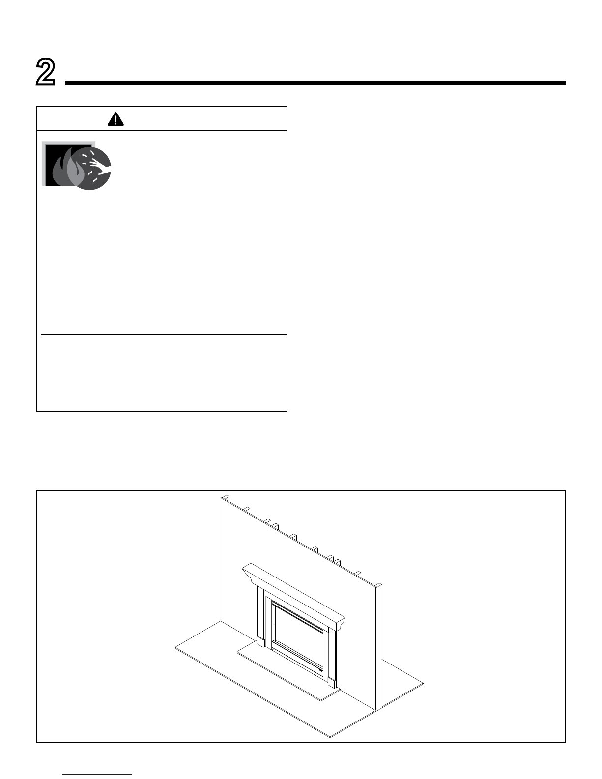
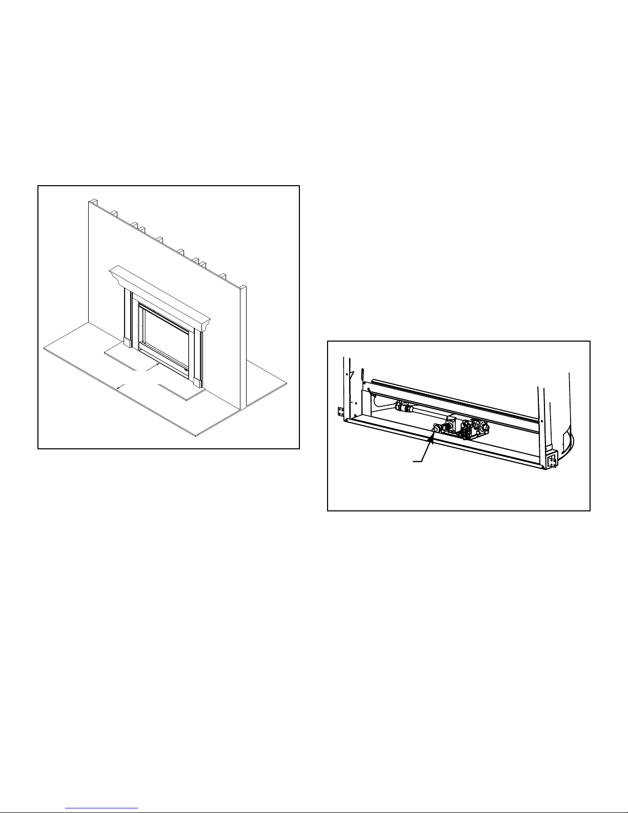
Fixed Glass Assembly
SECTION 14.K.
Log Set
(not shown)
SECTION 2.B.
Mantel
SECTION 13.A.
Hearth
(not required)
Clear Space
SECTION 2.D.
Fan Kit
SECTION 2.C
Figure 2.1 General Operating Parts
B. Your Fireplace
WARNING! DO NOT operate replace before reading and
understanding operating instructions. Failure to operate
replace according to operating instructions could cause
re or injury.
If you expect that small children or vulnerable adults may
come into contact with this replace, the following precautions are recommended:
A. Gas Fireplace Safety
• Install a physical barrier such as:
- A decorative rescreen.
- Adjustable safety gate.
• Install a switch lock or a wall/remote control with child
protection lockout feature.
• Keep remote controls out of reach of children.
• Never leave children alone near a hot replace, whether
operating or cooling down.
• Teach children to NEVER touch the replace.
• Consider not using the replace when children will be
present.
Contact your dealer for more information, or visit: www.
hpba.org/staysafe.
To prevent unintended operation when not using your
replace for an extended period of time (summer months,
vacations, trips, etc):
• Remove batteries from remote controls.
• Turn off wall controls.
• Unplug 3 volt adapter plug and remove batteries on IPI
models.
• Turn off gas controls valve on standing pilot models.
2
Operating Instructions
User Guide
HOT SURFACES!
Glass and other surfaces are hot
during operation and cool down.
Hot glass will cause burns.
• Do not touch glass until it is cooled
• NEVER allow children to touch glass
• Keep children away
• CAREFULLY SUPERVISE children in
WARNING
same room as appliance.
• Alert children and adults to ha zards of high
temperatures.
High temperatures may ignite clothing or other
ammable materials.
• Keep clothing, fu r n i t u r e , draperies and ot h e r
combustibles away.
This appliance has been supplied with an integral
barrier to prevent direct contact with the xed glass
panel. Do NOT operate the appliance with the barrier
removed.
Contact your dealer or Hearth & Home Technologies if the
barrier is not present or help is needed to properly install one.
When lighting the pilot light on replaces with a standing
pilot, remove the xed glass assembly so you can detect
presence of residual gas build-up. See Standing Pilot
Lighting instructions and Maintenance Tasks.
Heatilator • Eclipse • 4049-229 Rev I • 08/0910
Clear space 3 ft (914 mm)
in front of appliance
D. Clear Space
WARNING! DO NOT place combustible objects in front of
the replace or block louvers. High temperatures may start
a re. See Figure 2.2.
Avoid placing candles and other heat-sensitive objects on
mantel or hearth. Heat may damage these objects.
Figure 2.2 Clear Space
E. Fixed Glass Assembly
See Section 15.B.
F. Remote Controls, Wall Controls and Wall
Switches
Follow the instructions supplied with the control installed
to operate your replace:
For safety:
• Install a switch lock or a wall/remote control with child
protection lockout feature.
• Keep remote controls out of reach of children.
See your dealer if you have questions.
G. Before Lighting Fireplace
Before operating this replace for the rst time, have a
qualied service technician:
• Verify all shipping materials have been removed from
inside and/or underneath the rebox.
• Review proper placement of logs, ember material and/or
other decorative materials.
• Check the wiring.
• Check the air shutter adjustment.
• Ensure that there are no gas leaks.
• Ensure that the glass is sealed and in the proper position
and that the integral barrier is in place.
WARNING! Risk of Fire or Asphyxiation! DO NOT oper-
ate replace with xed glass assembly removed.
Determine if this replace has a standing pilot or an
Intellire ignition system. Ask your dealer or open control
access panel, look at gas valve assembly.
• A standing pilot ignition will have a red or black ignitor
button (refer to Figure 2.3).
• An Intellire ignition system will not have a button.
Red or Black
Button
Figure 2.3 Ignitor Button
C. Fan Kit
• Optional
• Contact your dealer for the correct fan kit.

Heatilator • Eclipse • 4049-229 Rev I • 08/09 11
H. Lighting Instructions (IPI)
The IPI system may be operated with two D-cell batteries. When using batteries, unplug the transformer. To prolong battery life, remove them when using the transformer.
A. This appliance is equipped with an ignition device which
automatically lights the pilot. Do not try to light the pilot
by hand.
B. BEFORE LIGHTING smell all around the appliance area
for gas. Be sure to smell next to the floor because some
gas is heavier than air and will settle on the floor.
WHAT TO DO IF YOU SMELL GAS
• Do not try to light any appliance.
• Do not touch any electric switch; do not use any
phone in your building.
• Immediately call your gas supplier from a neighbor's
phone. Follow the gas supplier's instructions.
• If you cannot reach your gas supplier, call the fire
department.
LIGHTING INSTRUCTIONS
1. STOP! Read the safety information above on this label.
2. Turn wall switch to the "OFF" position or thermostat to
the lowest setting.
3. Turn off all electric power to the appliance.
4. This appliance is equipped with an ignition device which
automatically lights the pilot. Do NOT try to light the pilot
by hand.
5. Wait five minutes to clear out any gas. If you then smell gas,
STOP! Follow "B" in the safety information above on this label. If
you don't smell gas, go to the next step.
6. To turn on the burner, turn on all electric power to this appliance
and turn on the wall switch or set the thermostat to the desired
setting.
7. If the appliance will not operate, follow the instructions "TO TURN
OFF GAS TO APPLIANCE" and call your service technician or gas
supplier.
TO TURN OFF GAS TO APPLIANCE
1. Turn off wall switch or set thermostat to lowest setting.
2. Turn off all electric power to the appliance if service is to
be performed.
3. Push the gas control lever in and move to the "OFF"
position or push the gas control lever to the "OFF"
position. Do not force.
4. Replace the control access panel.
Due to high surface temperatures, keep children, clothing and furniture away.
Keep burner and control compartment clean. See installation and operating instructions accompanying the appliance.
WARNING: If you do not follow these instructions exactly, a
fire or explosion may result causing property
damage, personal injury or loss of life.
FOR YOUR SAFETY READ BEFORE LIGHTING
33631D
C. Use only your hand to push in and move the gas control
valve or turn the gas control knob. Never use tools. If the
lever or knob will not move by hand, don't try to repair it,
call a qualified service technician. Force or attempted
repair may result in a fire or explosion.
D. Do not use this appliance if any part has been under
water. Immediately call a qualified service technician to
inspect the appliance and to replace any part of the
control system and any gas control which has been
under water.
This appliance needs fresh air for safe operation and must
be installed so there are provisions for adequate
combustion and ventilation air.
This appliance must be installed in accordance
with local codes, if any; if not, follow ANSI
Z223.1 or, in Canada, current CAN/CGA-B149.
WARNING: Improper installation,
adjustment, alteration, service or maintenance
can cause injury or property damage. Refer to
the owner's information manual provided with
the appliance. For assistance or additional
information consult a qualified installer, service
agency or the gas supplier.
CAUTION: Hot while in operation. Do not touch.
Keep children, clothing, furniture, gasoline and other liquids
having flammable vapors away.
WARNING RISK OF FIRE
This appliance is intended to burn a specified gas fuel only. Do
not attempt to use with solid wood fuel or another type of fuel.
Do not attempt to modify or use any other type of gas burner
system.
* Also certified for installation in a bedroom or
a bed-sitting room.
* For U.S. only!
WARNING:
Disconnect the electric power before
servicing. If for any reason the original wire supplied with the
appliance must be replaced, it must be replaced with 105° C or its
equivalent.
For use with natural gas or propane. A conversion
kit as supplied by the manufacturer shall be used
to convert this appliance to the alternative fuel.
This appliance must be properly connected to a
venting system in accordance with the
manufacturer's installation instructions.
NATURAL GAS

Heatilator • Eclipse • 4049-229 Rev I • 08/0912
I. Lighting Instructions (Standing Pilot)
A. This appliance has a pilot which must be lighted by hand.
When lighting the pilot, follow these instructions exactly.
B. BEFORE LIGHTING smell all around the appliance area for
gas. Be sure to smell next to the floor because some gas is
heavier than air and will settle on the floor.
WHAT TO DO IF YOU SMELL GAS
• Do not try to light any appliance.
• Do not touch any electric switch; do not use any phone in
your building.
• Immediately call your gas supplier from a neighbor's phone.
Follow the gas supplier's instructions.
• If you cannot reach your gas supplier, call the fire
department.
LIGHTING INSTRUCTIONS
1. Turn wall switch to the "OFF" position or thermostat to the
lowest setting.
2. Remove control access panel.
3. Turn manual gas valve to CLOSED. Wait five [5] minutes to
clear out any gas. If you then smell gas, STOP! Follow "B" in
the safety information above on this label. If you don't smell
gas, go to next step.
4. Turn gas line to "OPEN".
5. Turn pilot knob clockwise to "OFF". (Knob may have to be
depressed to pass "PILOT" position.)
6. Locate pilot assembly inside appliance.
7. Locate red ignitor button.
8. Turn pilot knob to "PILOT" and push in.
9. Continue to hold in pilot knob and push the red ignitor button
12-15 times until small blue pilot flame appears.
10. Continue to hold in pilot knob for approximately one minute.
Pilot should remain lit. If pilot goes out, wait 5 minutes and
repeat Steps 3-9.
11. Release and turn knob counterclockwise to "ON".
12. If appliance will not operate, follow the instructions "TO TURN
OFF GAS TO APPLIANCE" and call your service technician or
gas supplier.
NOTE: To light main burner, turn wall switch to "ON". Do not light by
hand.
TO TURN OFF GAS TO APPLIANCE
1. Turn off wall switch or set thermostat to lowest setting.
2. Remove control access panel.
3. Turn manual gas valve to "CLOSED position. Do not force.
4. Replace control access panel.
Due to high surface termperatures, keep children, clothing and furniture away.
Keep burner and control compartment clean. See installation and operating instructions accompanying the appliance.
WARNING: If you do not follow these instructions exactly, a fire or
explosion may result causing property damage,
personal injury or loss of life.
FOR YOUR SAFETY READ BEFORE LIGHTING
29097D
This appliance needs fresh air for safe operation
and must be installed so there are provisions for
adequate combustion and ventilation air.
This appliance must be installed in accordance with
local codes, if any; if not, follow ANSI Z223.1 or, in
Canada, current CAN/CGA-B149.
WARNING:
Improper installation,
adjustment, alteration, service or maintenance can
cause injury or property damage. Refer to the owner's
information manual provided with the appliance. For
assistance or additional information consult a
qualified installer, service agency or the gas supplier.
CAUTION:
Hot while in operation. Do not touch.
Keep children, clothing, furniture, gasoline and other liquids
having flammable vapors away.
WARNING RISK OF FIRE
This appliance is intended to burn a specified gas
fuel only. Do not attempt to use with solid wood fuel
or another type of fuel. Do not attempt to modify or
use any other type of gas burner system.
* Also certified for installation in a bedroom or a
bed-sitting room.
* For U.S. only!
C. Use only your hand to push in or turn knob. Never use tools. If
the manual gas valve will not push in or turn by hand, don't try
to repair it; call a qualified service technician. Force or
attempted repair may result in a fire or explosion.
D. Do not use this appliance if any part has been under water.
Immediately call a qualified service technician to inspect the
appliance and to replace any part of the control system and
any gas control which has been under water.
Stop! Read the safety information above on this label.
ON
OFF
PILOT
OFF
PILOT
ON
OFF
PILOT
5
ON
OFF
VENT
ON
7
5
8
11
3. CLOSED
4. OPEN
WARNING:
Disconnect the electric power
before servicing. If for any reason the original wire
supplied with the appliance must be replaced, it must be
replaced with 105° C or its equivalent.
For use with natural gas or propane. A conversion
kit as supplied by the manufacturer shall be used to
convert this appliance to the alternative fuel.
This appliance must be properly connected to a
venting system in accordance with the
manufacturer's installation instructions.
NATURAL GAS
Heatilator • Eclipse • 4049-229 Rev I • 08/09 13
Initial Break-in Procedure
• The fireplace should be run three to four hours
continuously on high.
• Turn the replace off and allow it to completely cool.
• Remove xed glass assembly. See Section 15.B.
• Clean xed glass assembly. See Section 3.
• Replace the xed glass assembly and run continuously
on high an additional 12 hours.
This cures the materials used to manufacture the replace.
NOTICE! Open windows for air circulation during replace
break-in.
• Some people may be sensitive to smoke and
odors.
• Smoke detectors may activate.
J. After Fireplace is Lit
L. Frequently Asked Questions
ISSUE SOLUTIONS
Condensation on the glass This is a result of gas combustion and temperature variations. As the appliance warms, this
condensation will disappear.
Blue ames This is a result of normal operation and the ames will begin to yellow as the appliance is allowed
to burn for 20 to 40 minutes.
Odor from appliance When rst operated, this appliance may release an odor for the rst several hours. This is caused
by the curing of materials from manufacturing. Odor may also be released from nishing materials
and adhesives used near the appliance. These circumstances may require additional curing
related to the installation environment.
Film on the glass This is a normal result of the curing process of the paint and logs. Glass should be cleaned within
3 to 4 hours of initial burning. A non-abrasive cleaner such as gas appliance glass cleaner may be
necessary. See your dealer.
Metallic noise Noise is caused by metal expanding and contracting as it heats up and cools down, similar to the
sound produced by a furnace or heating duct. This noise does not affect the operation or longevity
of the appliance.
Is it normal to see the pilot
ame burn continually?
In an IntelliFire ignition system (IPI), the pilot ame should turn off when appliance is turned off.
Some optional control systems available with IPI models may allow pilot ame to remain lit. In a
standing pilot system the pilot will always stay on.
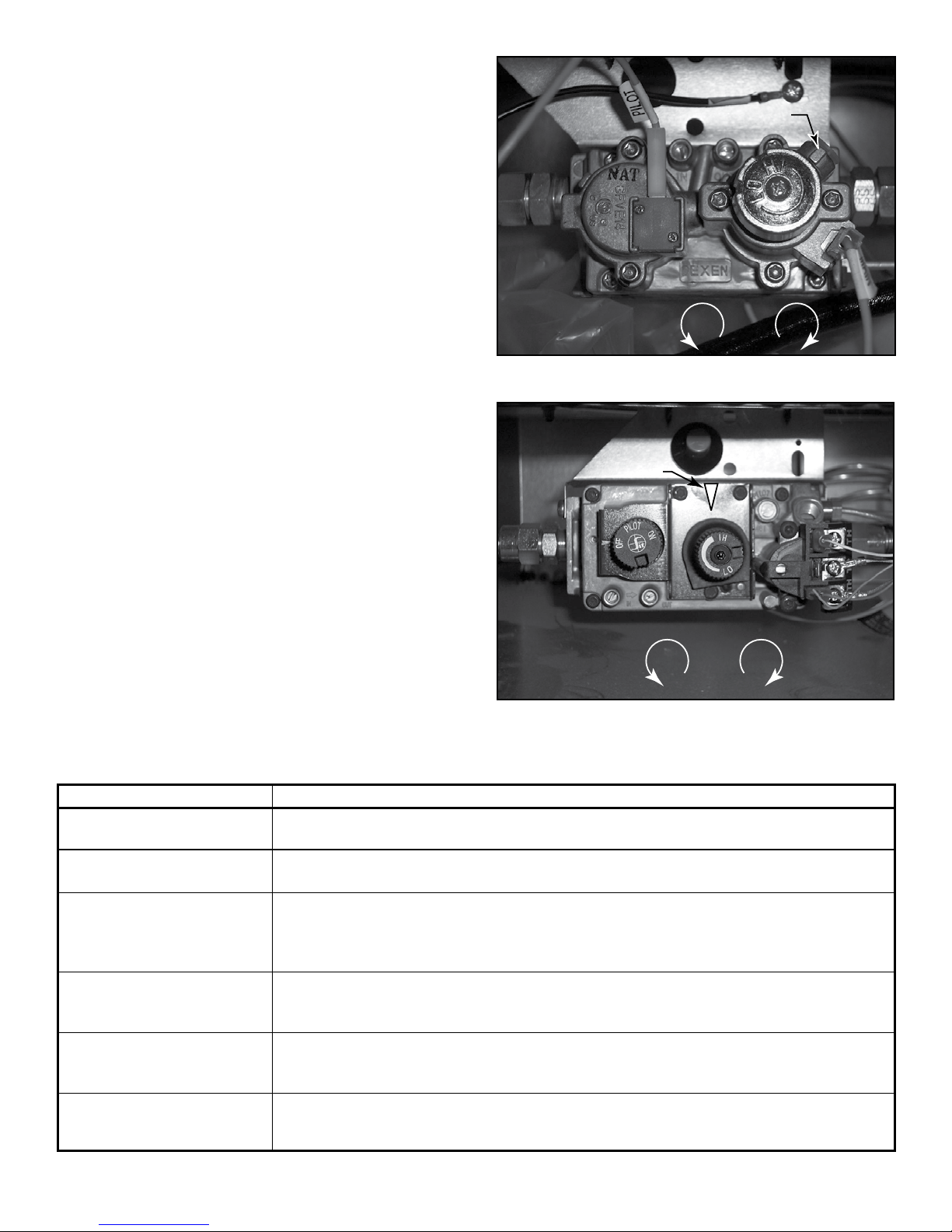
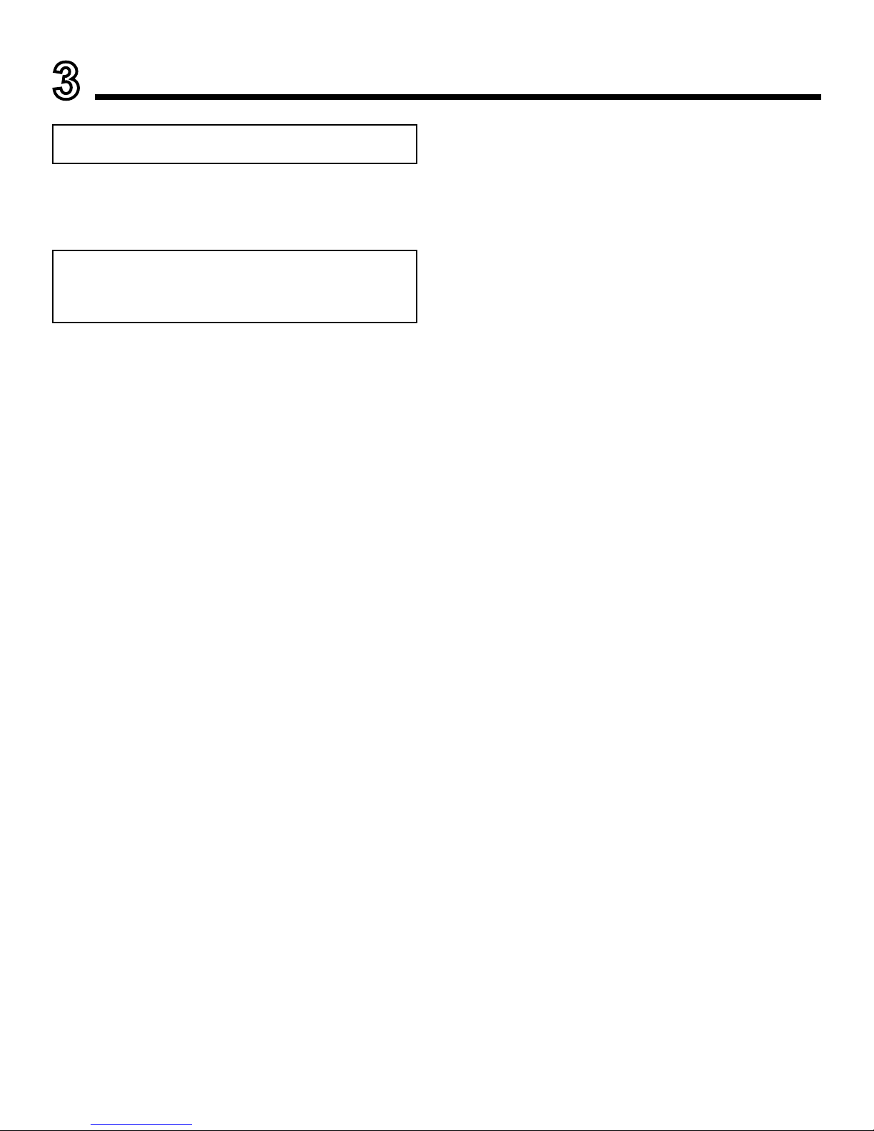
K. Flame Adjustment Control
Some appliances come equipped with a high/low ame
adjustment control.
• Open control access panel
• Compare your valve to Figures 2.4 & 2.5.
• Adjust the ame by turning knob as indicated in the photo
matching your valve.
HILO
Indicator
Indicator
HI LO
Figure 2.4 DEXEN Valve - IntelliFire Ignition System
Figure 2.5 SIT Valve - Standing Pilot Ignition System
Heatilator • Eclipse • 4049-229 Rev I • 08/0914
Glass Cleaning
Frequency: Seasonally
By: Homeowner
Tools Needed: Protective gloves, glass cleaner, drop
cloth and a stable work surface.
CAUTION! Handle xed glass assembly with care.
Glass is breakable.
• Avoid striking, scratching or slamming glass
• Avoid abrasive cleaners
• DO NOT clean glass while it is hot
• Prepare a work area large enough to accommodate xed
glass assembly and door frame by placing a drop cloth
on a at, stable surface.
Note: Fixed glass assembly and gasketing may have
residue that can stain carpeting or oor surfaces.
• Remove door or decorative front from replace and set
aside on work surface.
• See Section 15.B for instructions to remove xed glass
assembly.
3
Maintenance and Service
A. Maintenance Tasks-Homeowner
The following tasks may be performed annually by the
homeowner. If you are uncomfortable performing any of
the listed tasks, please call your dealer for a service appointment.
More frequent cleaning may be required due to lint from
carpeting or other factors. Control compartment, burner
and circulating air passageway of the replace must be
kept clean.
When properly maintained, your replace will give you
many years of trouble-free service. We recommend an-
nual service by a qualied service technician.
Doors, Surrounds, Fronts
Frequency: Annually
By: Homeowner
Tools needed: Protective gloves, stable work surface
• Assess condition of screen and replace as necessary.
• Inspect for scratches, dents or other damage and repair
as necessary.
• Check that louvers are not blocked.
• Vacuum and dust surfaces.
Remote Control
Frequency: Seasonally
By: Homeowner
Tools needed: Replacement batteries and remote control
instructions.
• Locate remote control transmitter and receiver.
• Verify operation of remote. Refer to remote control
operation instructions for proper calibration and setup
procedure.
• Place batteries as needed in remote transmitters and
battery-powered receivers.
• Place remote control out of reach of children.
If not using your replace for an extended period of time
(summer months, vacations/trips, etc), to prevent unin-
tended operation:
• Remove batteries from remote controls.
• Unplug 3 volt adapter plug on IPI models.
Any safety screen or guard removed for servicing must be
replaced prior to operating the replace.
Installation and repair should be done by a qualied
service technician only. The replace should be inspect-
ed before use and at least annually by a professional
service person.
CAUTION! Risk of Burns! The replace should be
turned off and cooled before servicing.
•
Clean glass with a non-abrasive commercially available
cleaner.
- Light deposits: Use a soft cloth with soap and
water
- Heavy deposits: Use commercial replace glass
cleaner (consult with your dealer)
• Carefully set xed glass assembly in place on replace.
Hold glass in place with one hand and secure glass
latches with the other hand. See Section 15.E. for glass
replacement.
• Reinstall door or decorative front.

Heatilator • Eclipse • 4049-229 Rev I • 08/09 15
Venting
Frequency: Seasonally
By: Homeowner
Tools needed: Protective gloves and safety glasses.
• Inspect venting and termination cap for blockage or
obstruction such plants, bird nests, leaves, snow, debris,
etc.
• Verify termination cap clearance to subsequent
construction (building additions, decks, fences, or
sheds). See Section 6.
• Inspect for corrosion or separation.
• Verify weather stripping, sealing and ashing remains
intact.
• Inspect draft shield to verify it is not damaged or
missing.
Control Compartment and Firebox Top
Frequency: Annually
By: Qualied Service Technician
Tools needed: Protective gloves, vacuum cleaner, dust
cloths
• Vacuum and wipe out dust, cobwebs, debris or pet hair.
Use caution when cleaning these areas. Screw tips that
have penetrated the sheet metal are sharp and should
be avoided.
• Remove all foreign objects.
• Verify unobstructed air circulation.
B. Maintenance Tasks-Qualied Service
Technician
The following tasks must be performed by a qualied
service technician.
Logs
Frequency: Annually
By: Qualied Service Technician
Tools needed: Protective gloves.
• Inspect for damaged or missing logs. Replace as
necessary. Refer to Section 15 for log reference.
• Verify correct log placement and no ame impingement
causing sooting. Correct as necessary.
Firebox
Frequency: Annually
By: Qualied Service Technician
Tools needed: Protective gloves, sandpaper, steel wool,
cloths, mineral spirits, primer and touch-up paint.
• Inspect for paint condition, warped surfaces, corrosion
or perforation. Sand and repaint as necessary.
• Replace replace if rebox has been perforated.
Gasket Seal and Glass Assembly Inspection
Frequency: Annually
By: Qualied Service Technician
Tools needed: Protective gloves, drop cloth and a stable
work surface.
• Inspect gasket seal and its condition.
• Inspect xed glass assembly for scratches and nicks
that can lead to breakage when exposed to heat.
• Conrm there is no damage to glass or glass frame.
Replace as necessary.
• Verify that xed glass assembly is properly retained and
attachment components are intact and not damaged.
Replace as necessary.
Burner Ignition and Operation
Frequency: Annually
By: Qualied Service Technician
Tools needed: Protective gloves, vacuum cleaner, whisk
broom, ashlight, voltmeter, indexed drill bit set, and a
manometer.
• Verify burner is properly secured and aligned with pilot
or igniter.
• Clean off burner top, inspect for plugged ports, corrosion
or deterioration. Replace burner if necessary.
• Replace rockwool materials with new dime-size pieces.
DO NOT block ports or obstruct lighting paths. Refer to
Section 15 for proper rockwool placement.
• Verify batteries have been removed from battery backup IPI systems to prevent premature battery failure or
leaking.
• Check for smooth lighting and ignition carryover to all
ports. Verify that there is no ignition delay.
• Inspect for lifting or other ame problems.
• Verify air shutter setting is correct. See Section 15 for
required air shutter setting. Verify air shutter is clear of
dust and debris.
• Inspect orice for soot, dirt and corrosion. Verify orice
size is correct. See Service Parts List for proper orice
sizing.
• Verify manifold and inlet pressures. Adjust regulator as
required.
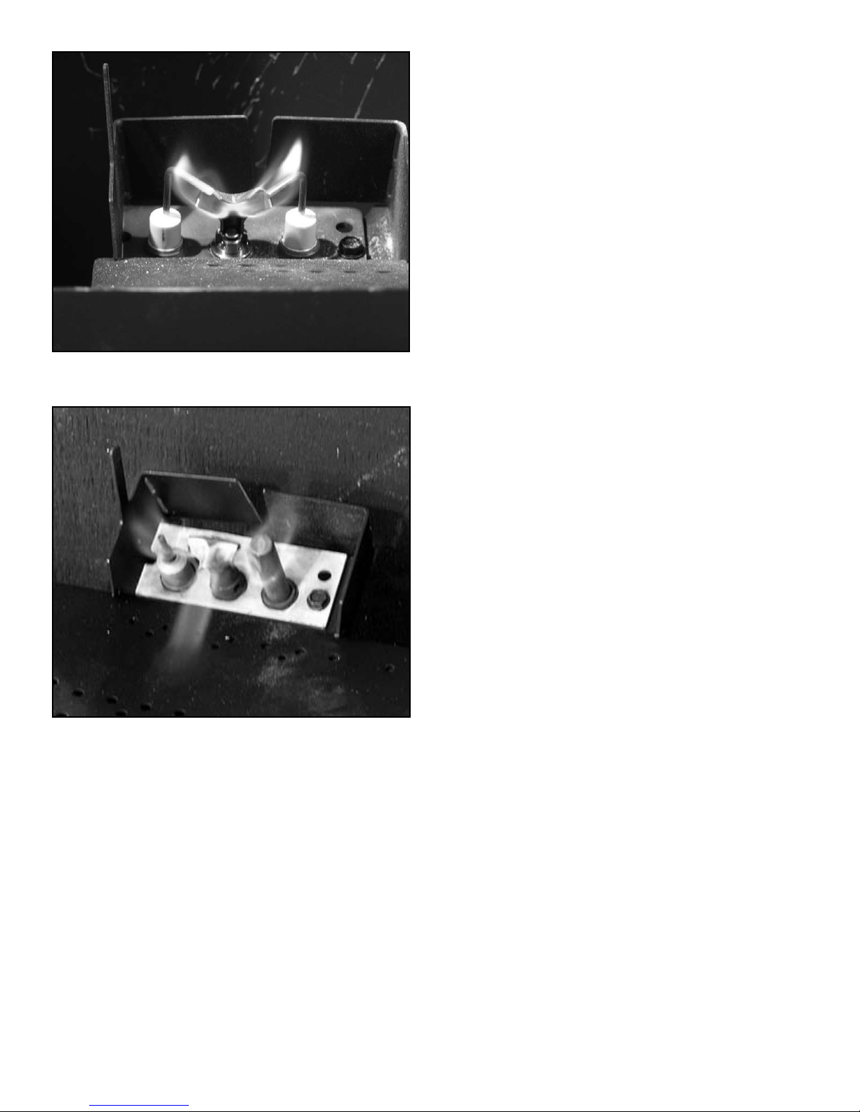
• Inspect pilot ame pattern and strength. See Figure 3.1
and 3.2 for proper pilot ame pattern. Clean or replace
orice spud as necessary.
• Inspect thermocouple/thermopile or IPI ame sensing
rod for soot, corrosion and deterioration. Clean with
emery cloth or replace as required.
• Verify thermocouple/thermopile or IPI millivolt output.
Replace as necessary.
Heatilator • Eclipse • 4049-229 Rev I • 08/0916
(Either cobrahead or SIT)
PRODUCT SPECIFIC
Figure 3.1 IPI Pilot Flame Patterns
Figure 3.2 Standing Pilot Flame Patterns
Heatilator • Eclipse • 4049-229 Rev I • 08/09 17
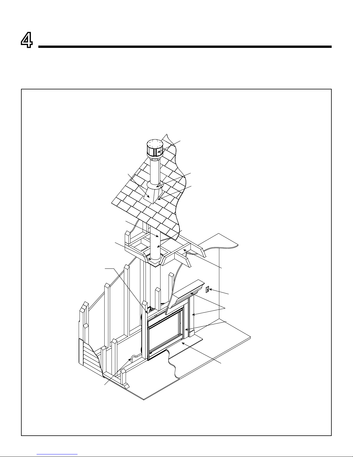
Noncombustible roof
flashing maintains minimum
clearance around pipe
(SECTION 10)
Ceiling Firestop
on floor of attic
(SECTION 8)
Vent Pipe
(SECTIONS 7, 8, 10)
Framing/Header
(SECTION 5)
Gas Line
(SECTION 11)
Framing Headed off
in Ceiling Joists
(SECTION 8)
Mantel & Mantel Leg
(SECTION 13)
Surround
Hearth Extension
(not required)
Optional
Wall Switch
Vertical Termination Cap
(SECTION 10)
Storm Collar
(SECTION 10)
Attic insulation shield (not shown) must be used here to
keep insulation away from vent pipe if attic is insulated.
(SECTION 8)
Vent pipe penetrates roof,
preferably without affecting
roof rafters
(SECTION 8)
A. Typical Appliance System
NOTICE: Illustrations and photos reect typical installations and are for design purposes only. Illustrations/diagrams are not
drawn to scale. Actual product may vary from pictures in manual
Figure 4.1 Typical System
4
Getting Started
Installer Guide

Heatilator • Eclipse • 4049-229 Rev I • 08/0918
B. Design and Installation Considerations
Heatilator direct vent gas appliances are designed to operate with all combustion air siphoned from outside of the
building and all exhaust gases expelled to the outside. No
additional outside air source is required.
Installation MUST comply with local, regional, state and
national codes and regulations. Consult insurance carrier,
local building inspector, re ofcials or authorities having
jurisdiction over restrictions, installation inspection and
permits.
Before installing, determine the following:
• Where the appliance is to be installed.
• The vent system conguration to be used.
• Gas supply piping.
• Electrical wiring requirements.
• Framing and nishing details.
• Whether optional accessories—devices such as a fan or
remote control—are desired.
D. Inspect Appliance and Components
• Carefully remove the appliance and components from
the packaging.
• The vent system components and decorative doors and
fronts may be shipped in separate packages.
• If packaged separately, the log set and appliance grate
must be installed.
• Report to your dealer any parts damaged in shipment,
particularly the condition of the glass.
• Read all of the instructions before starting the installation.
Follow these instructions carefully during the installation
to ensure maximum safety and benet.
C. Tools and Supplies Needed
Before beginning the installation be sure that the following
tools and building supplies are available.
Tape measure Framing material
Pliers
High temperature caulking material
Hammer Phillips screwdriver
Gloves Framing square
Voltmeter Electric drill and bits (1/4 in.)
Plumb line Safety glasses
Level Reciprocating saw
Manometer Flat blade screwdriver
Non-corrosive leak check solution
1/2 - 3/4 in. length, #6 or #8 Self-drilling screws
One 1/4 in. female connection (for optional fan).
Hearth & Home Technologies disclaims any responsibility for,
and the warranty will be voided by, the following actions:
• Installation and use of any damaged appliance or vent system
component.
• Modication of the appliance or vent system.
• Installation other than as instructed by Hearth & Home
Technologies.
• Improper positioning of the gas logs or the glass door.
• Installation and/or use of any component part not approved
by Hearth & Home Technologies.
Any such action may cause a re hazard.
WARNING! Risk of Fire, Explosion or Electric Shock!
DO NOT use this appliance if any part has been under wa-
ter. Call a qualied service technician to inspect the appliance and to replace any part of the control system and/or
gas control which has been under water.
Improper installation, adjustment, alteration, service or
maintenance can cause injury or property damage. For
assistance or additional information, consult a qualied
service technician, service agency or your dealer.
WARNING! Risk of Fire or Explosion! Damaged parts
could impair safe operation. DO NOT install damaged, incomplete or substitute components. Keep appliance dry.
Heatilator • Eclipse • 4049-229 Rev I • 08/09 19
5
Framing and Clearances
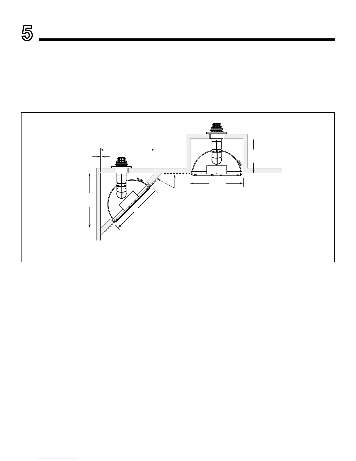
A. Selecting Appliance Location
When selecting a location for the appliance it is important
to consider the required clearances to walls (see Figure
5.1).
WARNING! Risk of Fire or Burns! Provide adequate
clearance around air openings and for service access. Due
to high temperatures, the appliance should be located out
of trafc and away from furniture and draperies.
NOTICE: Illustrations reect typical installations and are
FOR DESIGN PURPOSES ONLY. Illustrations/diagrams
are not drawn to scale. Actual installation may vary due to
individual design preference.
36-7/8 in.
934 mm
Horiz Term
36 in./914 mm
3/4 in./19 mm
minimum
appliance
to combustibles
17-7/8 in.
454 mm
Drywall
36-7/8 in.
934 mm
36 in.
914 mm
Figure 5.1 Appliance Locations
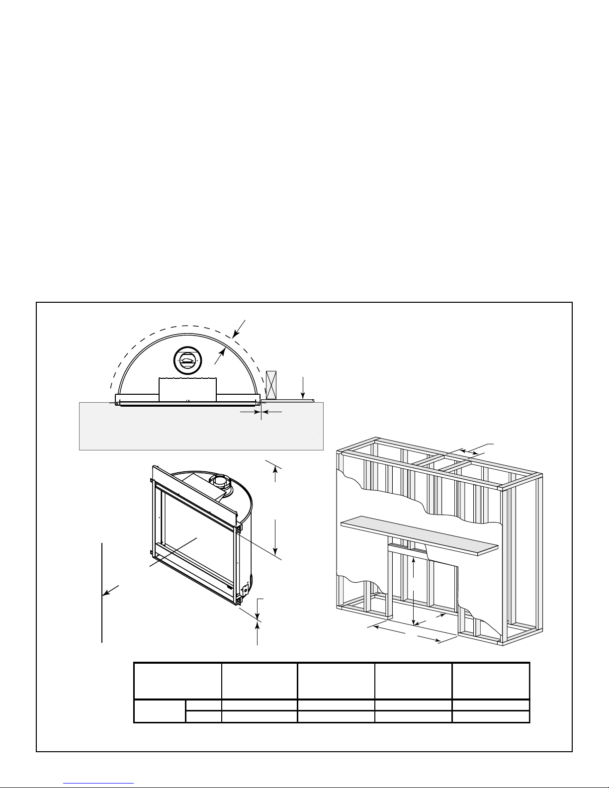
Heatilator • Eclipse • 4049-229 Rev I • 08/0920
Combustible flooring may be installed
next to the front of the appliance.
C
B
A
Drywall
0 in.
3/4 in.
(19 mm)
0 in. to floor
D
30 in.
(762 mm)
to ceiling
36 in.
(914 mm)
Combustible Object
A
Rough Opening
(Width)
B
Rough Opening
(Height)
C
Rough Opening
(Depth)
D
Rough Opening
(SLP Pipe)
inches
36 34 17 7/8 9
mm
914 864 454 229
Model
EDV3633
B. Constructing the Appliance Chase
A chase is a vertical box-like structure built to enclose the
gas appliance and/or its vent system. In cooler climates
the vent should enclosed inside the chase.
NOTICE: Treatment of ceiling restops and wall shield
restops and construction of the chase may vary with the
type of building. These instructions are not substitutes for the
requirements of local building codes. Therefore, you MUST
check local building codes to determine the requirements
to these steps.
Chases should be constructed in the manner of all outside walls of the home to prevent cold air drafting problems. The chase should not break the outside building
envelope in any manner.
Walls, ceiling, base plate and cantilever oor of the chase
should be insulated. Vapor and air inltration barriers
should be installed in the chase as per regional codes for
the rest of the home. Additionally, in regions where cold
air inltration may be an issue, the inside surfaces may
be sheetrocked and taped for maximum air tightness.
Figure 5.2 Clearances to Combustibles
C. Clearances
NOTICE: Install appliance on hard metal or wood surfaces
extending full width and depth. DO NOT install directly on
carpeting, vinyl, tile or any combustible material other than
wood.
WARNING! Risk of Fire! Maintain specied air space
clearances to appliance and vent pipe:
• Insulation and other materials must be secured to
prevent accidental contact.
• Failure to maintain airspace may cause overheating and
a re.
To further prevent drafts, the wall shield and ceiling re-
stops should be caulked with high temperature caulk to
seal gaps. Gas line holes and other openings should be
caulked with high temp caulk or stuffed with unfaced insu-
lation. If the appliance is being installed on a cement slab,
a layer of plywood may be placed underneath to prevent
conducting cold up into the room.
 Loading...