

Heatilator EC36, EC39, EC42 Installation & Operating Instructions Manual

INSTALLATION & OPERATING
INSTRUCTIONS
EC36 EC39 EC42
WOODBURNING FIREPLACE
Note: An arrow () found in the text signifies change in content.
WARNING!
Improper installation, adjustment, alteration, service or maintenance can cause injury or property damage. Refer to this
manual. For assistance or additional information, consult a qualified installer, service agency or the gas supplier.
08/04 17339 Rev L 1

EC SERIES INSTALLATION INSTRUCTIONS
Table of Contents
Design and Installation Considerations ......................................................................................... 3
A. Listings and Code Approvals ......................................................................................................... 4
B. Description of the Fireplace System .............................................................................................. 4
C. Fireplace System Components ..................................................................................................... 5
D. Pre-Installation Preparation ......................................................................................................... 10
E. Chimney Requirements ............................................................................................................... 12
F. Installation of Fireplace ............................................................................................................... 15
G. Constructing a Chase .................................................................................................................. 22
H. Operating Instructions .................................................................................................................25
I. Maintenance Instructions ............................................................................................................ 29
Index ........................................................................................................................................... 31
Warranty ..................................................................................................................................... 32
CAUTION:
Do not expose the fireplace to the elements (i.e. rain, etc.) and keep the fireplace dry at all times. Wet insulation
will produce an odor when the fireplace is used.
WARNING!
This fireplace is tested and listed for use only with the optional accessories listed in these instructions. Use of
optional accessories not specifically tested for this appliance could void the warranty and/or result in a safety
hazard.
Safety Precautions
1. Please read these installation instructions completely before beginning installation procedures. Failure to follow
them could cause a fireplace malfunction resulting in serious injury and/or property damage.
2. Always check your local building codes prior to installation. The installation must comply with all local, regional,
state and national codes and regulations.
3. An adequate supply of replacement combustion air from outside the house must be available to the fire for the
fireplace to operate properly. To achieve this, the use of the optional outside air kit is highly recommended.
In the event the home is unusually tightly sealed, the optional combustion air kit may not provide all the air required
to support combustion. Hearth & Home Technologies is not responsible for any smoking or related problems that
may result from the lack of adequate combustion air. It is the responsibility of the builder/contractor to ensure that
adequate combustion air has been provided for the fireplace.
4. The fireplace must be installed with the Hearth & Home Technologies SL Series Chimney System.
The chimney system must always terminate outside the building. Be sure to follow all chimney specifications given
in these installation instructions.
5. NEVER leave children unattended when there is a fire burning in the fireplace.
6. This fireplace is built for solid fuel only. NEVER use gasoline, gasoline type lantern fuel, kerosene, charcoal light
fluid, or similar liquids in this fireplace. Keep any flammable liquids a safe distance from the fireplace.
7. DO NOT use chimney cleaners or flame colorants in your fireplace.
8. The flue damper must be open at all times when the fireplace is in use.
9. While servicing this fireplace, always shut off any electricity or gas to the fireplace. This will prevent possible electric
shock or burns. Also, make sure the fireplace is completely cooled before servicing.
10. To ensure a safe fireplace system and to prevent the build up of soot and creosote, inspect and clean the fireplace
and chimney prior to use and periodically during the burning season. See “Maintenance Instructions” in this manual
for cleaning instructions.
2 17339 Rev L 08/04
EC SERIES INSTALLATION INSTRUCTIONS
DESIGN AND INSTALLATION CONSIDERATIONS
When selecting a location for your woodburning fireplace, it is important to evaluate a number of considerations. Modern
construction techniques can create conditions that may not allow your chimney to draft properly. This may result in
smoke spillage from your fireplace, as well as cause other combustion appliances to operate incorrectly.
Tightly sealed construction is important for energy efficiency. Unfortunately, a great deal of effort has been directed to
tightening up sidewall construction, while considerably less attention has been paid to tightening upper portions of the
warm air envelope (insulated ceilings). This has increased the “Stack Effect”, a condition that increases the negative
pressure generated by the structure. This negative pressure will directly affect the drafting performance of a fireplace
chimney. To minimize the negative pressure generated by stack effect, make certain that all duct work installed in the attic
spaces is sealed airtight. Minimize the number of recessed light fixtures installed in the insulated ceiling, and use sealed
recessed light fixtures. Finally, make certain the whole house fans and attic access panels are tightly sealed. These are
important design considerations that must be observed during the design and construction stage of the home.
If you desire to put a fireplace in your basement, we recommend that you consider a direct vent gas fireplace. Basements
always have a significant negative air pressure that causes the fireplace system to be more susceptible to smoke
spillage and cold flue back drafting. Since direct vent gas fireplaces are sealed, they are not affected by the negative
pressure that exists in basements.
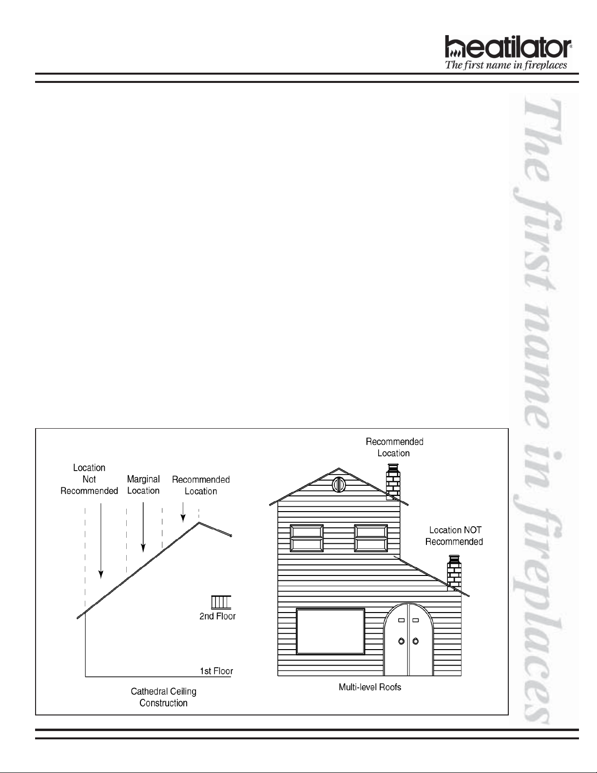
Finally, woodburning fireplaces perform best when their chimney (roof termination) is located on the upper half of the
roof, especially when cathedral ceilings are present. Chimneys that are located on the lower half of the roof realize what
is known as “lazy flue” and will not draft as well as a chimney that is located in the upper portion of the roof. The reason
for this is that the stack effect generated by the overall height of the living spaces inside the house will exceed the draft
generated by the chimney system. If you desire to place a woodburning fireplace in a location where the termination cap
would be located on the lower half of a roof, such as on an outside wall at the base of a cathedral ceiling, we recommend
that you consider using a direct vent gas fireplace. This will assure the homeowner a fireplace that operates correctly.
These properties do not affect just your woodburning factory built fireplace. They can cause any woodburning fireplace as
well as any conventionally vented (B-vent) gas appliance to operate improperly. Careful planning at this stage of your
project will ensure satisfaction with the operation of your fireplace once it is completed.
08/04 17339 Rev L 3
EC SERIES INSTALLATION INSTRUCTIONS
A. LISTINGS AND CODE APPROVALS
This fireplace system has been tested and listed in
accordance with UL127 and ULC-S610 standards, and has
been listed by Underwriters Laboratories Inc. for installation
and operation in the United States and Canada as described
in this manual.
This fireplace has been tested and listed for use with the
optional components listed on page 5. These optional
components may be purchased separately and installed
at a later date. However, installation of an outside air kit
will require significant reconstruction, and should be
installed at the time of the initial fireplace installation.
WARNING!
This fireplace and its components are designed to be installed and operated as a system. Any alteration to or
substitution for items in this system, unless allowed by these installation instructions, will void the Underwriters Laboratories listing and may void the product warranty. It may also create a hazardous installation. Read
through these instructions thoroughly before starting your installation and follow them carefully throughout
your project.
Check with your local building code agency prior to
installing this fireplace to ensure compliance with local
codes, including the need for permits and follow-up
inspections. If you need assistance during installation,
please contact your local dealer or the Heatilator Technical
Services Department, Hearth & Home Technologies Inc.,
1915 W. Saunders St., Mt. Pleasant, Iowa 52641
(1-800-927-6841).
Heatilator® is a registered trademark of Hearth & Home
Technologies Inc.
B. DESCRIPTION OF THE FIREPLACE SYSTEM
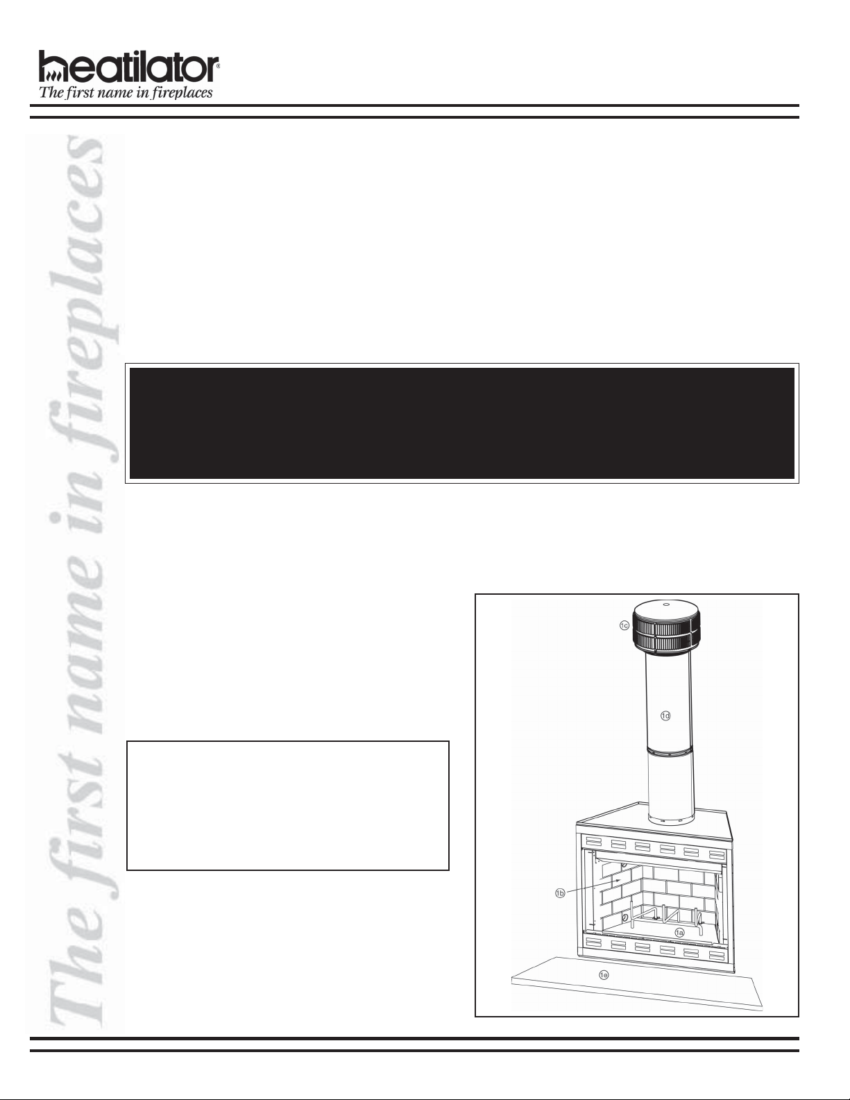
1. The Heatilator fireplace system consists of the following:
a. Fireplace/Integral Grate
b. Refractory
c. Chimney Termination Cap
d. Chimney System
e. Hearth Extension
2. Optional Components Include:
a. Glass Doors
b. Chimney Air Kit
c. Outside Combustion Air System
d. Fan Kit
Note: Illustrations used throughout these instructions
reflect “typical installations” and are for design purposes
only. Actual installation may vary slightly due to individual design preferences. However, minimum and maximum clearances must be maintained at all times.
The illustrations and diagrams used throughout these
installation instructions are not drawn to scale.
Figure 1 - Typical Fireplace System
4 17339 Rev L 08/04
EC SERIES INSTALLATION INSTRUCTIONS
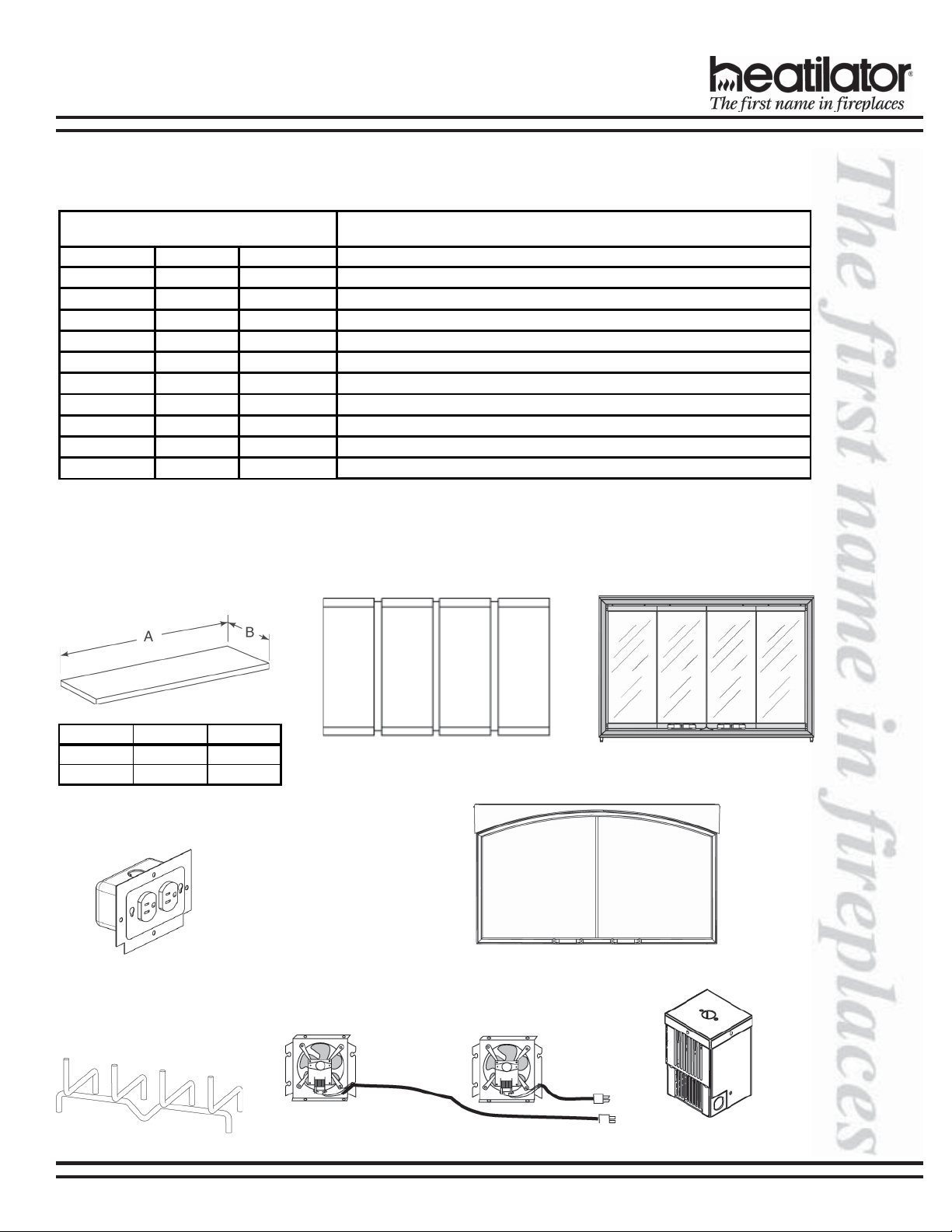
C. SYSTEM COMPONENTS
1. Fireplace Components
Catalog # Description:
E36 E39 E42 Fireplace, includes integral grate and hearth protection strips
HX3 HX3 HX4 Hearth Extension
DM1036 DM1039 DM1042 Original Bifold Glass Doors - Black Finish
DM1036B DM1039B DM1042B Original Bifold Glass Doors - Polished Brass Finish
DM1036S DM1039S DM1042S Original Bifold Glass Doors - Stainless Steel Finish
DP1036 none DP1042 Perception Glass Doors - Black Finish
DP1036B none DP1042B Perception Glass Doors - Polished Brass Finish
DP1036S none DP1042S Perception Glass Doors - Stainless Steel Finish
DMA1036B none DMA1042B Arched Cabinet Style Glass Doors - Polished Brass Finish
GR4 GR5 GR6 Integral Grate (i ncluded with fireplace)
AK14 Outside Air Kit
HEARTH EXTENSION GLASS DOORS
CAT. # A B
HX3 52 in. 16 in.
HX4 66 in. 20 in.
DM1036/DM1036B/DM1036S
DM1039/DM1039B/DM1039S
DM1042/DM1042B/DM1042S
JUNCTION BOX
JK8
INTEGRAL GRATE
(supplied)
FAN KIT
DMA1036B
DMA1042B
DP1036/DP1036B/DP1036S
DP1042/DP1042B/DP1042S
FK18
GR4, GR5, GR6
08/04 17339 Rev L 5
BC10
Fan Speed Control
EC SERIES INSTALLATION INSTRUCTIONS
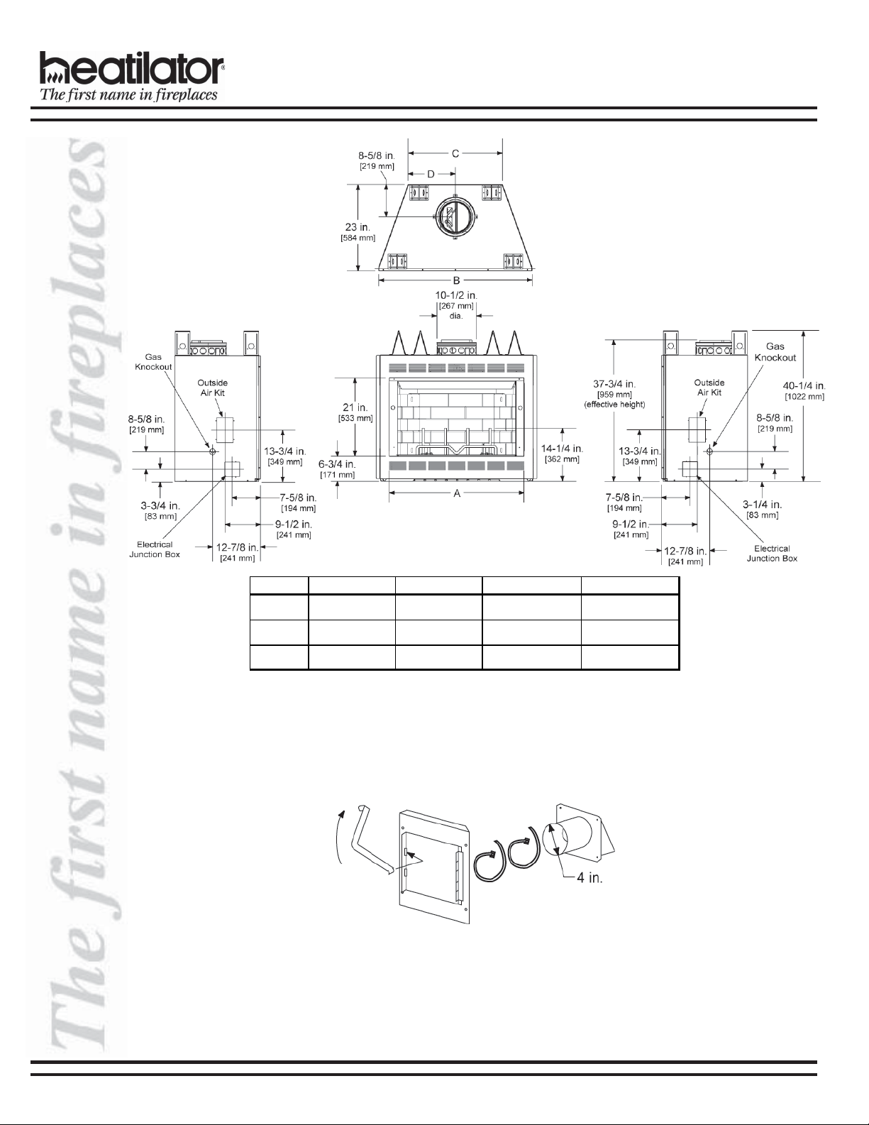
Cat . # A B C D
E/EC36 36 in. [914mm] 41 in. [1041mm] 25-1/4 in. [641mm] 12-5/8 in. [321mm]
E/EC39 39 in. [991mm] 44 in. [1118mm] 28-1/4 in. [718mm] 14-1/8 in. [359mm]
E/EC42 42 in. [1067mm] 47 in. [1194mm] 31-1/4 in. [794mm] 15- 5/8 in. [397mm]
Fireplace Dimensions
OUTSIDE AIR KIT
AK14
6 17339 Rev L 08/04
EC SERIES INSTALLATION INSTRUCTIONS
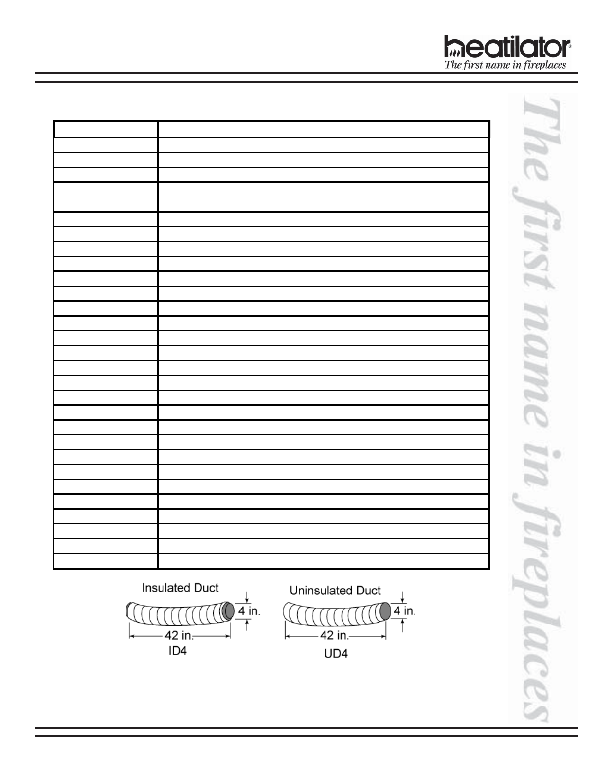
2. Chimney Components
The following pictures show only those chimney components which may be safely used with this fireplace.
Catalog # Description:
CAK4A Chimney Air Kit
ID 4 Insul a t e d D uct/Outsi de A i r
UD4 Uninsulated Duct/Outside Air
SL306 Chimney Section - 6 in. long
SL312 Chimney Section - 12 in. long
SL318 Chimney Section - 18 in. long
SL324 Chimney Section - 24 in. long
SL336 Chimney Section - 36 in. long
SL348 Chimney Section - 48 in. long
SL3 Chimney Stabilizer
SL315 Chimney Offset/Return - 15-degree
SL330 Chimney Offset/Return - 30-degree
FS338
FS339 Firestop - 15-degree
FS340 Firestop - 30-degree
AS8 SL300 Straight Attic Insulation Shield, 24 in.
JB877 Chimney Joint Band
CB876 Chimney Bracket
RF370 Roof Flashing - Flat to 6/12 Pitch
RF371 Roof Flashing - 6/12 to 12/12 Pitch
TR344 Round Termination Cap
TR342 Round Telescoping Termination Cap
ST375 Square Termination Cap
TS345 Square Termination Cap
TS345P Square Termination Cap - Painted
TCT375 Terra Cotta Termination Cap
CT35 Chase Top
LDS33 Decorative Shroud - 3 ft x 3 ft
LDS46 Decorative Shroud - 4 ft x 6 ft
Firestop - Straight
08/04 17339 Rev L 7
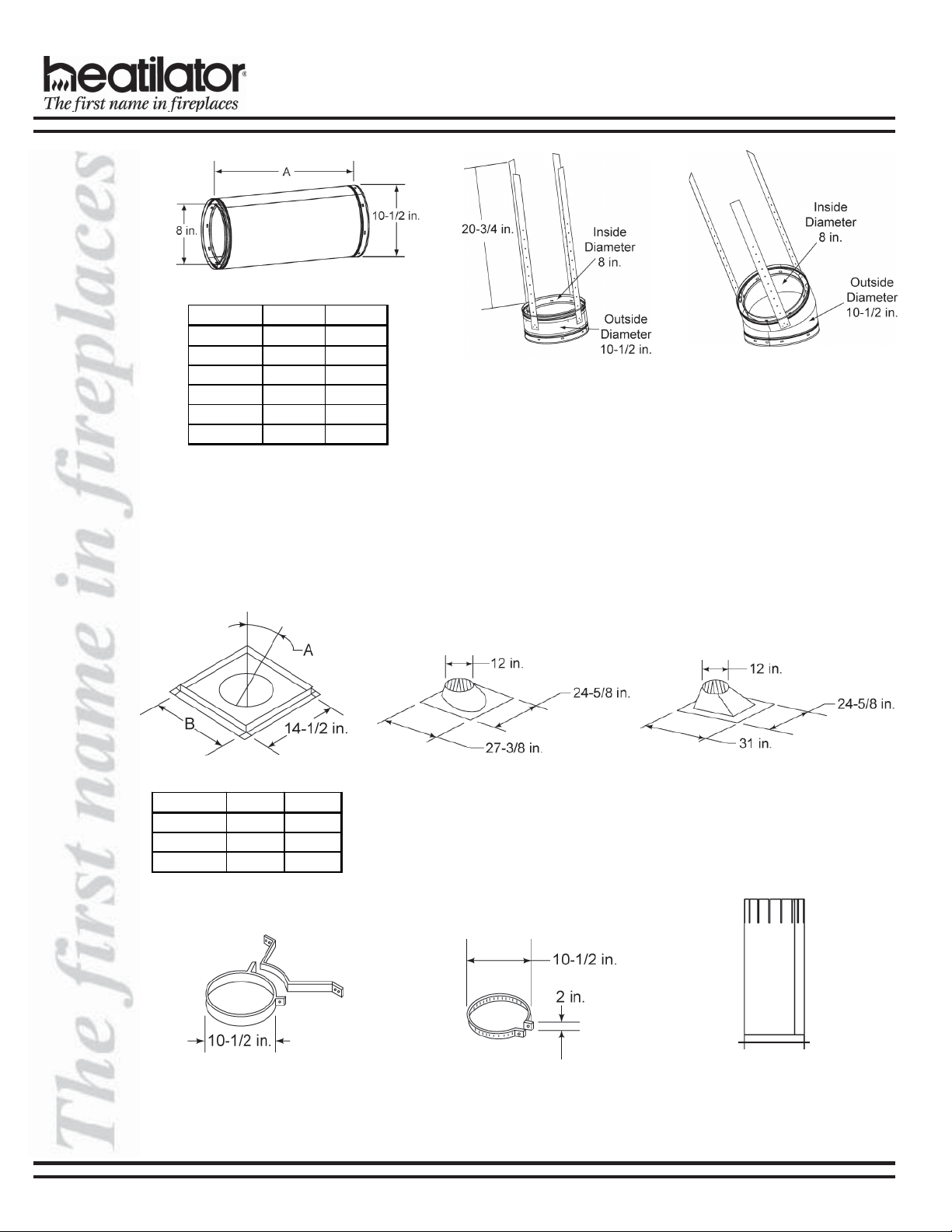
Chimney Sections
Catalog # A B
SL306 6 in. 4-3/4 in.
SL312 12 in. 10-3/4 in.
SL318 18 in. 16-3/4 in.
SL324 24 in. 22-3/4 in.
SL336 36 in. 34-3/4 in.
SL348 48 in. 46-3/4 in.
A = Actual Length
B = Effective length (length of
chimney part after it has
been snapped to another)
EC SERIES INSTALLATION INSTRUCTIONS
SL330 - Offset/Return
SL3 - Chimney Stabilizer
Firestop Spacer
RF370 - Roof Flashing
Flat to 6/12 Pitch
RF371 - Roof Flashing
6/12 to 12/12 Pitch
Catalog # A B
FS338 0-deg. 14-1/2 in.
FS339 15-deg. 18-3/8 in.
FS340 30-deg. 23 in.
CB876
Chimney Bracket
JB877
Joint Band
AS8
Straight Attic
Insulation Shield
8 17339 Rev L 08/04
EC SERIES INSTALLATION INSTRUCTIONS
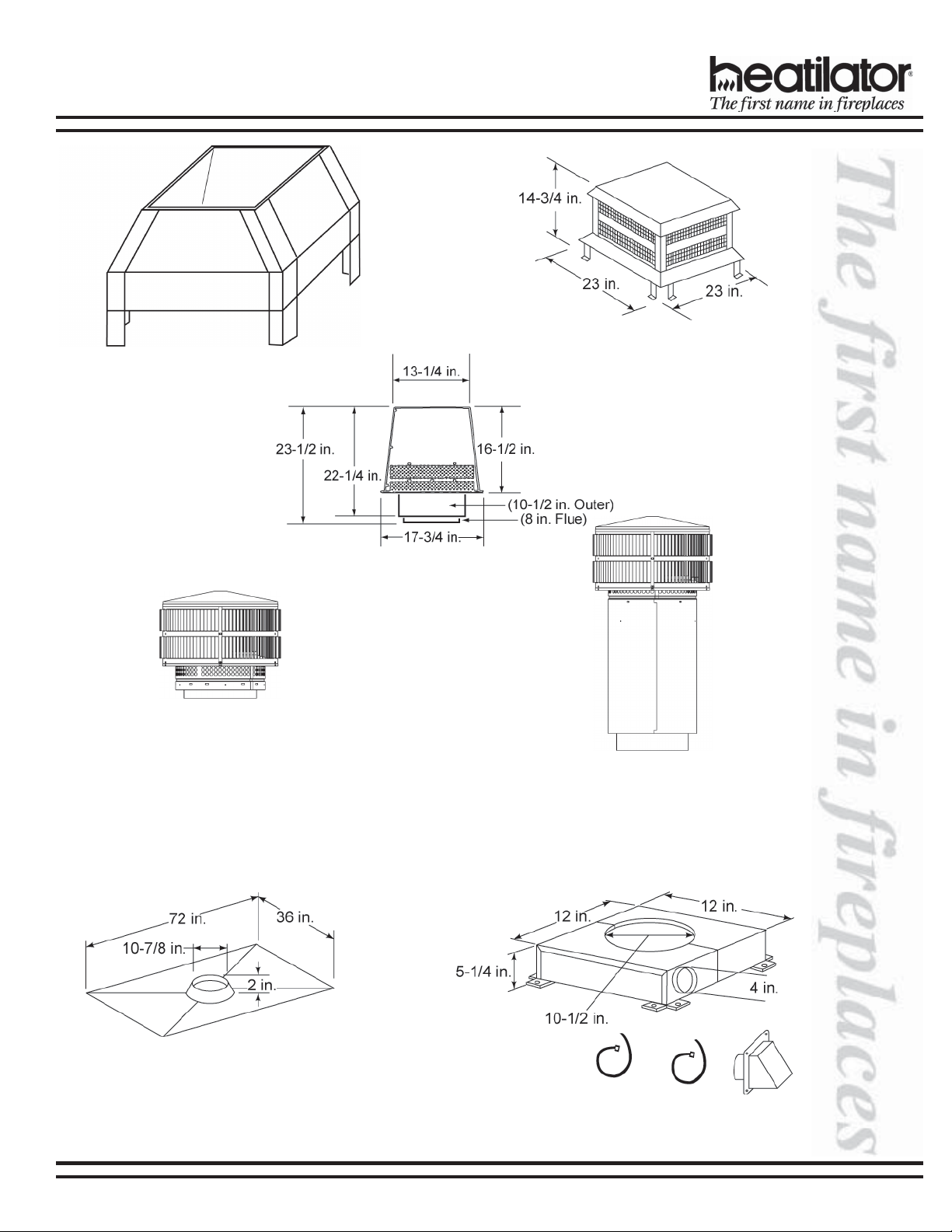
LDS33 (3 ft x 3 ft)
LDS46 (4 ft x 6 ft)
Decorative Shroud
ST375
Square
Termination Cap
TR344
Round
Termination Cap
TS345/TS345P
Square
Termination Cap
TR342
Round Telescoping
Termination Cap
CT35
Chase Top
CAK4A
Chimney Air Kit
08/04 17339 Rev L 9

EC SERIES INSTALLATION INSTRUCTIONS
D. PRE-INSTALLATION PREPARATION
1. Fireplace Locations and Space Requirements
Several options are available to you when choosing a location for your fireplace. This fireplace may be used as a
room divider, installed along a wall, across a corner or used in an exterior chase. See Figure 2.
Locating the fireplace in a basement, near frequently opened doors, central heat outlets or returns, or other locations
of considerable air movement can affect the performance and cause intermittent smoke spillage from the front of the
fireplace. Consideration should be given to these factors before deciding on a location.
CLEARANCES!
A minimum 1/2 in. air
clearance must be
maintained at the back and
sides of the fireplace
assembly.
Chimney sections at any level
require a 2 in. minimum air
space clearance between the
Figure 2 - Fireplace Locations
Figures 3 and 4 show two typical installations assuming an outside air kit is
being used. Therefore, an allowance must be made for 90-deg bends. Less
space is required when ducting goes directly outside without forming elbows.
framing and chimney section.
Cat . # A B
E/EC36 42 in. [1067mm] 45 in. [1143mm]
E/EC39 45 in. [1143mm] 48 in. [1219mm]
E/EC42 48 in. [1219mm] 51 in. [1295mm]
Figure 3
Installation Along a Wall or an Exterior Chase
These are rough framing
dimensions only.
Cat . # A B C D E
Figure 4 - Corner Installation
E/ EC36
E/ EC39
E/ EC42
42 in.
[1067mm]
45 in.
[1143mm]
48 in.
[1219mm]
72-3/4 in.
[1848mm]
75-3/4 in.
[1924mm]
78-3/4 in.
[2000mm]
36-3/8 in.
[924mm]
37-3/8 in.
[962mm]
39-3/8 in.
[1000mm]
15-5/8 in.
[ 39 7 mm]
16-5/8 in.
[ 42 2 mm]
17-5/8 in.
[ 44 8 mm]
51-3/8 in.
[1305mm]
53-1/2 in.
[1359mm]
55-3/8 in.
[1407mm]
WARNING!
Do not draw outside air from garage spaces. Exhaust products of gasoline engines are hazardous.
Do not install outside air ducts such that the air may be drawn from attic spaces, basements or above the
roofing where other heating appliances or fans and chimneys exhaust or utilize air. These precautions will
reduce the possibility of fireplace smoking or air flow reversal.
WARNING!
To prevent contact with sagging or loose insulation, the fireplace must not be installed against vapor barriers
or exposed insulation. Localized overheating could occur and a fire could result.
10 17339 Rev L 08/04
EC SERIES INSTALLATION INSTRUCTIONS
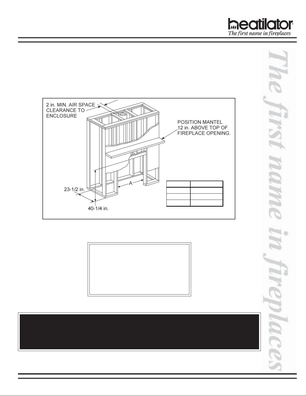
2. Frame the Fireplace
The EC Series fireplaces will fit a framed opening with the width shown in the Table below x 40-1/4 in. tall. The
finished cavity depth must be no less than 23-1/2 in.
Figure 5 shows a typical framing (using 2 x 4 lumber) of the fireplace, assuming combustible materials are used.
All required clearances to combustibles around the fireplace must be adhered to. Any framing across the top of the
fireplace must be above the level of the top standoffs. Chimney sections at any level require a 2 in. minimum air
space clearance between the framing and chimney section.
Ca t. # A
E/EC36 42 in. [1067mm]
E/EC39 45 in. [1143mm]
E/EC42 48 in. [1219mm]
Figure 5
Framing the Fireplace
CLEARANCES!
A minimum 1/2 in. air clearance must be
maintained at the back and sides of the
fireplace assembly.
Chimney sections at any level require a 2 in.
minimum air space clearance between the
framing and chimney section.
WARNING!
Do not apply combustible finishing materials over any part of the black face of this fireplace or a structure fire
may result. The black metal fireplace front may only be covered with noncombustible materials such as ceramic tile, brick, or stone. Do not cover or block any cooling air slots. Do not cover any portion of the opening to
the fireplace that would prevent the installation of an authorized glass door.
08/04 17339 Rev L 11
EC SERIES INSTALLATION INSTRUCTIONS
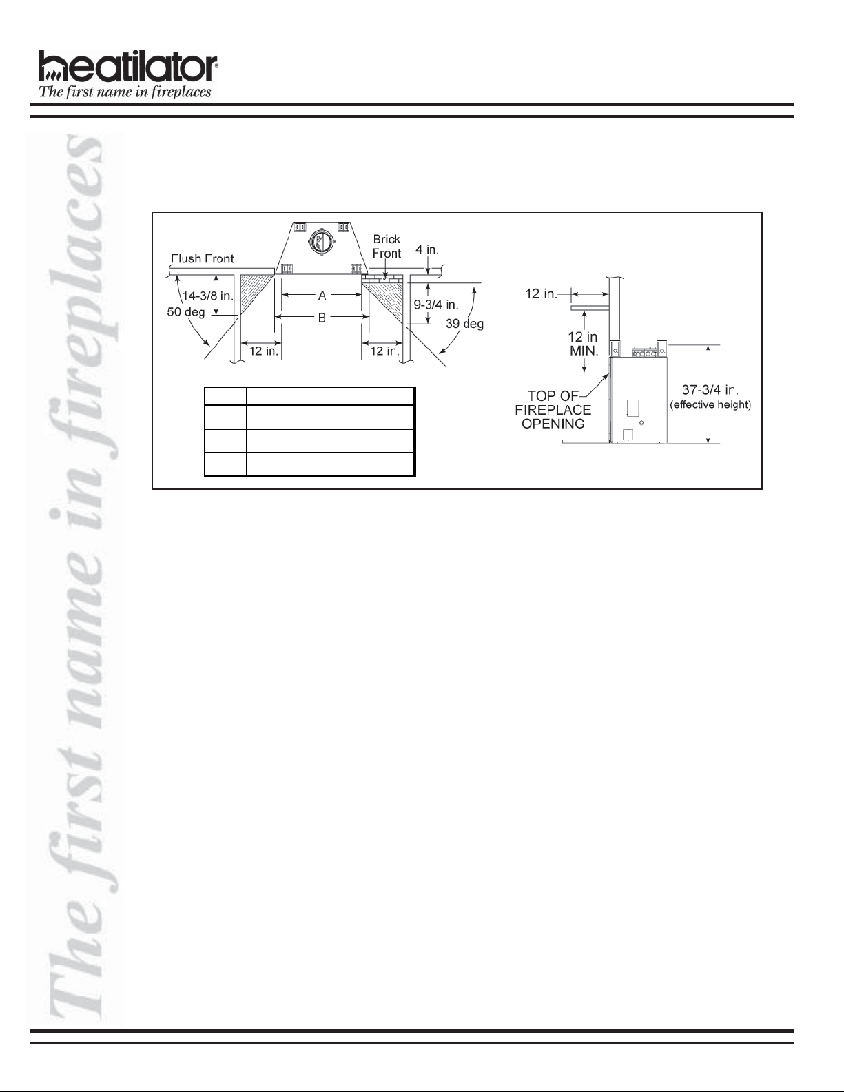
3. Sidewalls/Surrounds
Adjacent combustible side walls must be located a minimum of 12 in. from the fireplace opening. See Figure 6. If
you are using a decorative surround constructed of combustible material, it must be located within the shaded area
defined in Figure 6. Short stub walls are also acceptable if they are contained within the shaded area.
Cat . # A B
E/EC36 36 in. [914mm] 41 in. [1041mm]
E/EC39 39 in. [991mm] 44 in. [1118mm]
E/EC42 42 in. [1067mm] 47 in. [1194mm]
Figure 6 - Sidewalls and Surrounds
E. CHIMNEY REQUIREMENTS
When planning your fireplace location, the chimney construction and necessary clearances must be considered. The
fireplace system and chimney components have been tested to provide flexibility in construction. The following figures
are the minimum distances from the base of the fireplace.
1. Minimum overall straight height 13 ft
2. Minimum height with offset/return 14.5 ft
3. Maximum height 90 ft
4. Maximum chimney length between an offset and return 20 ft
5. Maximum distance between chimney stabilizers 35 ft
6. Double offset/return minimum height 24 ft
7. Maximum unsupported chimney length between the offset and return 6 ft
8. Maximum straight unsupported chimney height above the fireplace 35 ft
12 17339 Rev L 08/04
EC SERIES INSTALLATION INSTRUCTIONS
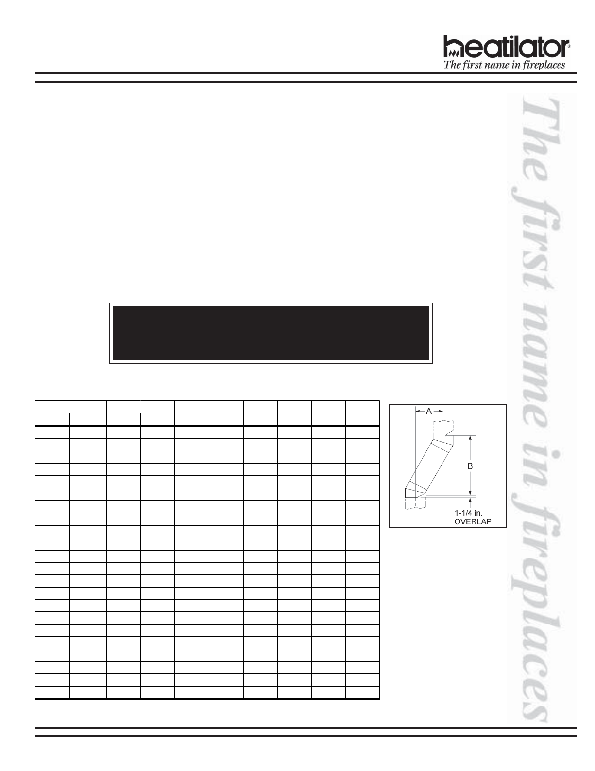
1. Using Offsets and Returns
a. To bypass any overhead obstructions, the chimney may be offset using a 15-deg or 30-deg offset/return.
Perform the following steps to determine the correct chimney component combination for your particular
installation.
b. An offset and return may be attached together or a chimney section(s) may be used between an offset and
return.
1) Measure how far the chimney needs to be shifted to enable it to avoid the overhead obstacle. See Figure 7,
dimension “A” to determine chimney sections required to achieve the needed shift.
2) After determining the offset dimension, refer to Table 1 and find the “A” dimension closest to but not less
than the distance of shift needed for your installation.
3) The “B” dimension that coincides with the “A” dimension represents the required vertical clearance that is
needed to complete the offset and return.
4) Read across the chart and find the number of chimney sections required and the model number of those
particular chimney parts.
5) Whenever the chimney penetrates a floor/ceiling, a firestop spacer must be installed.
6) The effective height of the fireplace assembly is measured from the base of fireplace to top of starter
collar. See Figure 6.
WARNING!
Do not combine offsets to create an offset greater than 30 deg from vertical. This may create a fire hazard since the natural draft may be restricted.
Table 1 Offset Chart*
15-degree 30-degree
ABAB
1-5/8 in.13-3/8 in.3-7/8 in.14-1/2 in.------
2-7/8 in.17-3/4 in.6-1/4 in.18-5/8 in.1-----
4-1/8 in.22-3/8 in.8-5/8 in.22-3/4 in.2-----
4-1/2 in. 23-5/8 in. 9-1/4 in. 23- 3/4 in. - 1 - - - -
5-3/4 in. 28-1/4 in. 11 -5/8 in. 27-7/8 in. 1 1 - - - -
6 in. 29-3/8 in. 12-1/4 in. 29 in. - - 1 - - -
7-1/4 in. 34 in. 14-5/8 in. 33 in. - 2 - - - -
7-3/4 in. 36-1/8 in. 15 -1/4 in. 34-1/8 in. - - - 1 - -
8-3/4 in. 39-3/4 in. 17 -5/8 in. 38-1/4 in. 1 - - 1 - -
10-3/8 in. 45-5/8 in. 20-5/8 in. 43-1/2 in. - - 2 - - -
10-5/8 in.46-3/4 in.21-1/4 in.44-5/8 in.----1-
11-7/8 in. 51-3/8 in. 23-5/8 in. 48-3/8 in. 1 - - - 1 -
13-1/2 in. 57-1/4 in. 26-5/8 in. 53-7/8 in. - - - 2 - -
13-3/4 in.58-3/8 in.27-1/4 in.55-3/4 in.-----1
15 in.63 in.29-5/8 in.59 in.1----1
16-1/2 in. 68-3/4 in. 32-5/8 in. 64-1/4 in. - 1 - - - 1
18 in. 74-5/ 8 in. 35-5/8 in. 69-1/2 in. - - 1 - - 1
19-5/8 in. 80-3/8 in. 38-5/8 in. 74-5/8 in. - - - 1 - 1
20-5/8 in. 84-1/8 in. 41 in. 78-3/4 in. 1 - - 1 - 1
22-3/4 in.91-7/8 in.44-5/8 in.85 in.----11
24 in. 96-1/ 2 in. 47 in. 89- 1/8 in. 1 - - - 1 1
25-7/8 in. 103 -1/2 in. 50 -5/8 in. 95-1/2 in.
SL306 SL312
-----
SL318 SL324 SL336 SL348
* Proper assembly of air cooled chimney parts result in an overlap at chimney
joints of 1¼”. Effective length is built into this chart.
Figure 7 - Chimney Offset/
Return
Example: Your “A”
dimension from Figure 7 is
14-1/2 in. Using Table 1 the
dimension closest to, but
not less than 14-1/2 in. is
14-5/8 in. using a 30-deg
offset/return. It is then
determined from the table
that you would need 33 in.
(Dimension “B”) between
the offset and return. The
chimney components that
best fit your application are
two SL312s.
08/04 17339 Rev L 13
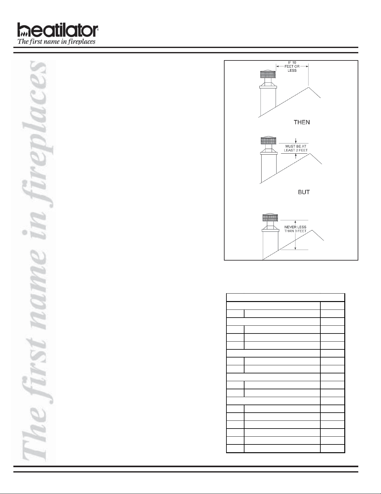
2. Chimney Height Requirements (above
roof line)
a. Major building codes specify a minimum chimney
height above the roof top. These specifications
are summarized in what is known as the Ten Foot
Rule. This rule states:
“If the horizontal distance from the side of the
chimney to the peak of the roof is 10 ft or less, the
top of the chimney must be at least 2 ft above the
peak of the roof, but never less than 3 ft in overall
height above the highest point where it passes
through the roof.
“If the horizontal distance from the side of the
chimney to the peak of the roof is more than 10 ft,
a chimney height reference point is established
on the surface of the roof a distance of 10 ft from
the side of the chimney in a horizontal plane. The
top of the chimney must be at least 2 ft above this
reference point, but never less than 3 ft in height
above the highest point where it passes through
the roof.” See Figure 8.
b. These chimney heights are necessary in the
interest of safety but do not ensure smoke-free
operation. Trees, buildings, adjoining roof lines,
adverse wind conditions, etc. may create a need
for a taller chimney should smoking occur.
EC SERIES INSTALLATION INSTRUCTIONS
3. Number of Sections Required
To determine the chimney components needed to
complete your particular installation, follow the steps
below:
a. Determine the total vertical height of the fireplace
installation. This dimension is measured from
the base of the fireplace assembly to the point
where the smoke exits the termination cap.
b. Subtract the effective height of the fireplace
assembly from the overall height of the fireplace
installation (measured from the base of the
fireplace to the bottom of the termination cap).
c. Refer to Table 2 to determine what components
must be selected to complete the fireplace
installation.
d. Determine the number of firestop spacers,
stabilizers, roof flashing, etc. required to
complete the fireplace installation.
Figure 8 - Chimney Height
Table 2
HEIGHT OF CHIMNEY COMPONENTS
Chimney Stabilizer
SL3 4-3/4 in.
Firestop Spacers
FS33 8 0 in.
FS33 9 0 in.
FS34 0 0 in.
Offsets/Returns
SL315 13-3/8 in.
SL330 14-1/2 in.
Roof Flashing
RF3 70 0 in .
RF3 71 0 in .
Chimney Sections*
SL306 4-3/4 in.
SL312 10-3/4 in.
SL318 16-3/4 in.
SL324 22-3/4 in.
SL336 34-3/4 in.
SL348 46-3/4 in.
* Dimensions reflect effective height
14 17339 Rev L 08/04
EC SERIES INSTALLATION INSTRUCTIONS
F. INSTALLATION OF FIREPLACE
WARNING!
Before starting, do the following:
1. Wear gloves and safety glasses for protection.
2. Keep hand tools in good condition. Sharpen cutting edges and make sure tool handles are secure.
3. Always maintain the minimum air space required to the enclosure to prevent fire.
1. Position the Fireplace
This fireplace may be placed on either a combustible
or noncombustible continuous flat surface. Follow the
instructions for framing on pages 10-12. Slide the
fireplace into position. Be sure to provide the
minimum air clearance at the sides and back of
the fireplace assembly.
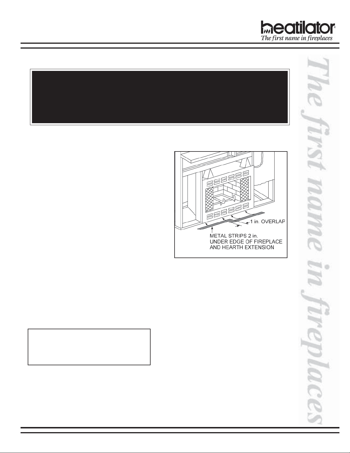
2. Place the Protective Metal Hearth Strips
Included with your fireplace you will find two metal
hearth strips measuring approximately 26 in. x 4 in.
These strips are used to provide added protection
where the fireplace and the hearth extension meet.
Slide each metal strip 2 in. under the front edge of the
fireplace. The individual pieces must overlap each
other by 1 in. minimum in the middle of the fireplace
to provide continuous coverage of the floor. See
Figure 9. These metal strips should extend from the
front and sides of the fireplace opening by 2 in.
Figure 9 - Positioning the Metal Strips
3. Level the Fireplace
Level the fireplace side-to-side and front-to-back. Shim
with noncombustible material, such as sheet metal,
as necessary. Secure the fireplace (using the nailing
flanges located on either side of the fireplace) to the
vertical framing.
Important: To ensure proper fit of the glass doors,
check the fireplace opening for square. Measure
diagonal distances of the opening to make sure
they are equal. If they are not equal, continue to
shim the fireplace until those diagonals are equal.
08/04 17339 Rev L 15

4. Assemble Chimney Sections
Attach either a straight chimney section or an offset to
the top of the fireplace (depending on your installation
requirement). Chimney sections are locked together
by pushing downward until the top section meets the
stop bead on the lower section.
The inner flue is placed to the inside of the flue section
below it. The outer casing is placed outside the outer
casing of the chimney section below it. See Figure 10.
WARNING!
Carefully follow the instructions for assembly
of the pipe and other parts needed to install this
fireplace system. Failure to do so may result in
a fire, especially if combustibles are too close
to the fireplace or chimney and air spaces are
blocked, preventing the free movement of
cooling air.
EC SERIES INSTALLATION INSTRUCTIONS
Figure 10
Assembling Chimney
Sections
5. Install Firestop Spacers
Mark and cut out an opening in the ceiling for the
firestop spacer being utilized (14-1/2 in. x 14-1/2 in.
for an FS338, 14-1/2 in. x 18-3/8 in. for an FS339
and 14-1/2 in. x 23 in. for an FS340). Frame the
opening with the same dimension lumber used in
the ceiling joists.
Install the firestop spacer.
These firestop spacers are designed to provide the
minimum 2 in. air space required around the
chimney. In all situations, the firestop spacers are to
be nailed to the ceiling joists from the bottom or
fireplace side, EXCEPT when the space above is an
insulated ceiling or attic space. In this situation, the
firestop spacer must be nailed from the top side to
prevent loose insulation from falling into the
required 2 in. air space around the chimney. See
Figure 11.
CAUTION:
Firestop spacers must be used whenever the
chimney penetrates a ceiling/floor area.
Figure 11
Installing the Firestop Spacer
16 17339 Rev L 08/04
EC SERIES INSTALLATION INSTRUCTIONS
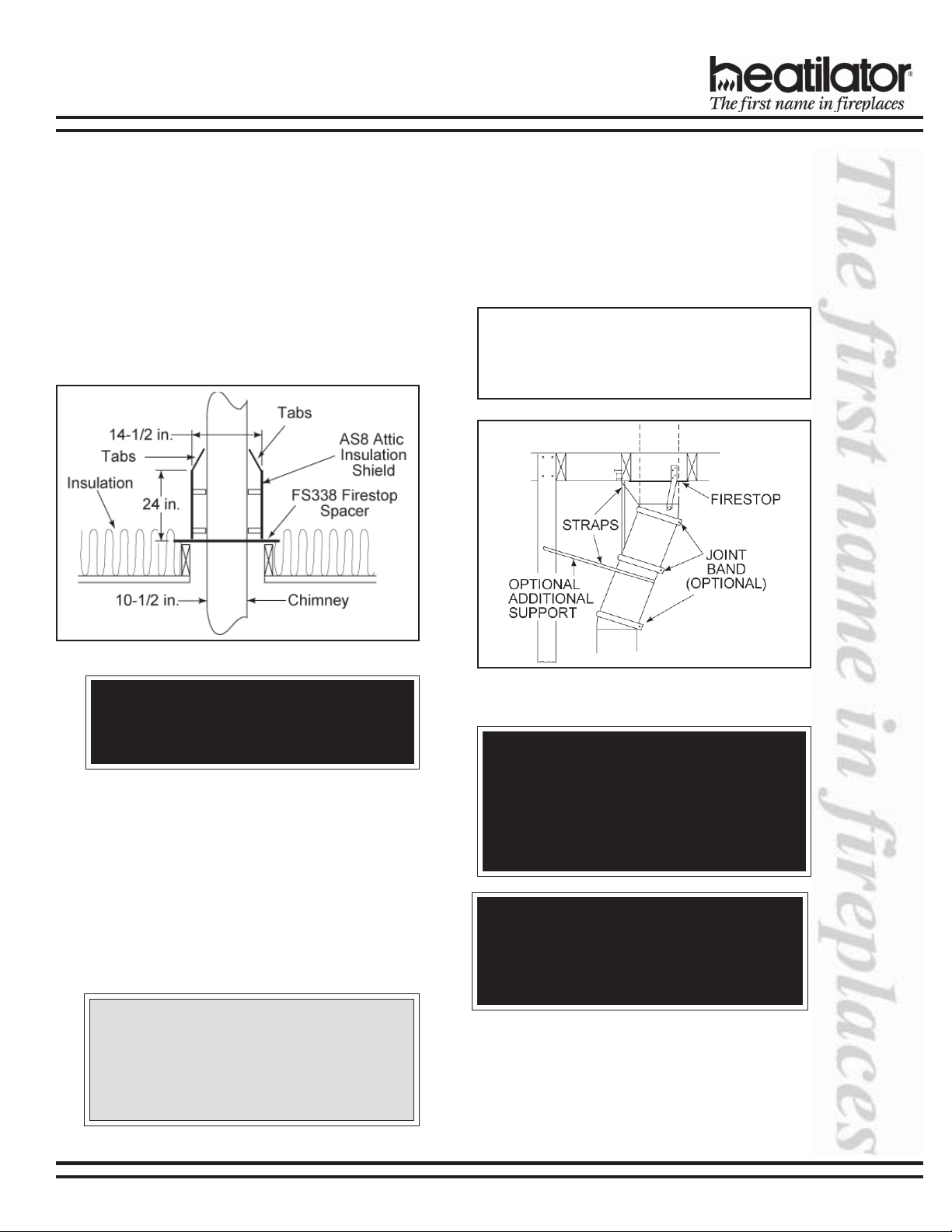
6. Attic Insulation Shield
An insulation shield should be installed when there
is a possibility of insulation coming into contact with
the factory built chimney system.
a. Bend the tabs at the top of the attic insulation
shield inward. This will help keep the chimney
section centered in the shield.
b. Position the shield over the vertical chimney
section where it penetrates a firestop spacer.
c. Slide the shield down until it rests on the firestop
spacer. The firestop spacer will support the
insulation shield. See Figure 12.
8. Secure Chimney System
When offsets and returns are joined to straight pipe
sections, they must be locked into position with the
screws provided (outer only), using the predrilled holes.
To prevent gravity from pulling the chimney sections
apart, the returns and the chimney stabilizers have
straps for securing these parts to joists or rafters. See
Figure 13.
Note: You must provide support for the pipe during
construction and check to be sure inadvertent loading has not dislodged the chimney section from the
fireplace or at any chimney joint.
Figure 12 - Installing an Attic Insulation Shield
WARNING! RISK OF FIRE.
Do not fill the space between the chimney
section and the insulation shield with insulation.
7. Double-check the Chimney Assembly
Continue assembling the chimney sections up through
the firestop spacers as needed. While doing so, be
aware of the height and unsupported chimney length
limitations that are given on page 12 under “Chimney
Requirements”.
Check each section by pulling up slightly from the top
to ensure proper engagement before installing the
succeeding sections. If they have been connected
correctly, they will not disengage when tested.
CAUTION:
Inner flue and outer liner sections cannot be disassembled once locked together. Plan ahead
to ensure the proper installation height is
achieved with the selected chimney components.
Figure 13 - Offset/Return with Stabilizer
WARNING!
When chimney sections exceeding 6 ft in length
are installed between an offset and return,
structural support must be provided to reduce
off-center loading and prevent chimney sections
from separating at the chimney joints.
WARNING!
Maintain a minimum of 2 in. air clearance to all
parts of the chimney system at all times! Fail-
ure to maintain this 2 in. air clearance will cause
a structure fire.
08/04 17339 Rev L 17
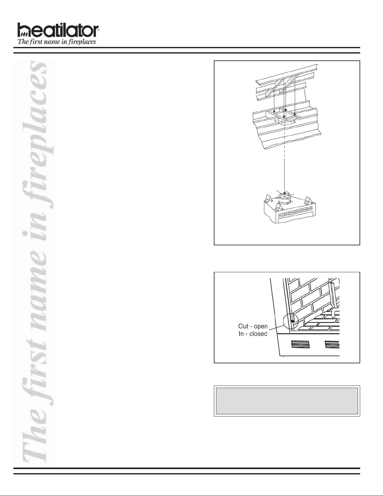
9. Mark the Exit Point of the Roof
Locate the point where the chimney will exit the roof
by plumbing down to the center of the chimney. Drive
a nail up through the roof to mark the center. See
Figure 14.
10. Cut out the Hole in the Roof
Measure to either side of the nail and mark the
14-1/2 in. x 14-1/2 in. opening required. This is
measured on the horizontal; actual length may be
larger depending on the pitch of the roof. Cut out and
frame the opening. See Chapter 25 of the Uniform
Building Code for roof framing details.
Be sure to maintain a 2 in. minimum air space
between the chimney section and the roof.
11. Assemble the Chimney Sections
Through the Roof
Continue to add chimney sections through the roof
opening, maintaining at least a 2 in. air space.
EC SERIES INSTALLATION INSTRUCTIONS
12. Install the Roof Flashing
If a roof flashing is to be used, install the roof flashing
appropriate to the roof pitch and install a round
termination cap following the instructions shipped with
the cap.
For chase installations you can use a round termination
cap (TR344), a round telescoping termination cap
(TR342) or a square termination cap (ST375/TS345/
TS345P). A chase installation must use a chase top.
Chase tops are available from your Heatilator
distributor. See page 22 for building a chase.
13. Install the Outside Air Kit
The outside air kit is an optional feature with this
fireplace and its use is highly recommended to
minimize the effects of negative pressure within the
structure. It is recommended to utilize the shortest duct
run to optimize the performance of the outside air kit.
The outside air kit inlet thimble should be positioned
at least 4 ft above the ground level, in a manner that
will not allow snow, leaves, etc. to block the inlet.
The outside air kit is installed on the left hand side of
the fireplace. Remove the cover plate from the side of
the fireplace assembly where the air kit is to be
installed. See Figure 15 for handle location/operation.
Figure 14 - Ceiling/Attic Construction
Figure 15 - Air Kit Handle Location
CAUTION:
The air kit handle may get hot while burning the
fireplace. Use care when operating the handle.
14. Install the Chimney Air Kit (Required in
Canada)
When installing the chimney air kit, follow the
instructions provided with this accessory.
18 17339 Rev L 08/04
EC SERIES INSTALLATION INSTRUCTIONS
15. Complete the Enclosure
Complete the fireplace enclosure, allowing space for
outside air ducts and gas piping if desired. Electrical
wiring should not come in contact with the fireplace. A
minimum clearance of 1/2 in. must be maintained
between the fireplace sides and the enclosure as
well as the fireplace back and the enclosure. See
pages 10-12 for framing details.
Note: Use only a noncombustible material to finish
the face of the fireplace below the level of the front
standoffs. A noncombustible material such as USG
MICORE CV230 Mineral Fiber Board, or USG
DUROCK Cement Board is recommended for this
purpose.
CAUTION:
When using a gas log set, the fireplace damper
must be set in the fully open position. This ensures proper venting of combustion products.
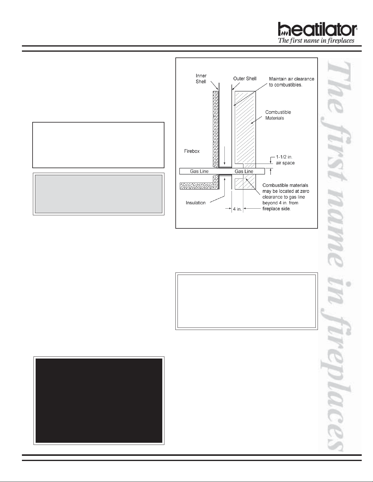
16. Gas Log/Lighter Provisions
Knockouts are provided on both sides of the fireplace
to allow for connection of a certified gas log lighter or
a decorative gas appliance with a maximum input of
100,000 BTU/hour, incorporating an automatic gas
shut-off device and complying with the Standard for
Decorative Gas Appliances for Installation in
Vented Fireplaces, ANSI Z21.60. The decorative gas
appliance should be installed in accordance with the
National Fuel Gas Code, ANSI Z223.1-1980. The side
refractories are designed to allow 1/2 in. iron pipe to
pass through. Use a noncombustible sealant to seal
any opening between the gas pipe and refractory on
the inside. Repack the insulation removed to seal
around the gas pipe where it exits the side of the
fireplace. A minimum 1-1/2 in. air clearance must be
provided around the 1/2 in. iron pipe for a minimum of
4 in. beyond the fireplace. See Figure 16.
WARNING!
This fireplace was not tested by the fireplace
manufacturer for use with an unvented gas log
heater. To reduce risk of injury, do not install an
unvented gas log heater in this fireplace unless
it has been specifically tested and listed by
Underwriter’s Laboratories Inc. for use in this
specific model fireplace. Unless the unvented
gas log heater is tested and listed for use in
this factory built fireplace, a fire hazard may be
created that can result in a structure fire.
Figure 16 - Air Clearance Around Gas Line
CLEARANCES!
A minimum 1/2 in. air clearance must be maintained
at the back and sides of the fireplace assembly.
Chimney sections at any level require a 2 in.
minimum air space clearance between the framing
and chimney section.
08/04 17339 Rev L 19
EC SERIES INSTALLATION INSTRUCTIONS
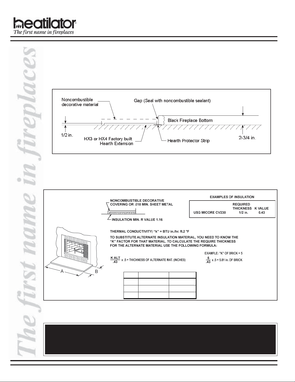
17. Hearth Extension
A hearth extension must be installed with all fireplaces to protect the combustible floor in front of the fireplace from
both radiant heat and sparks.
The construction of, and materials used for a hearth extension are shown in Figures 17 and 18. A hearth extension of
this construction may be covered with any noncombustible decorative material and may have a maximum thickness
as per the illustration. Seal gaps between the hearth extension and the front of the fireplace with a bead of
noncombustible sealant.
Figure 17 - Factory Built Hearth Extension
Field constructed hearth extensions should be constructed in accordance with the instructions in Figure 18. The field
constructed hearth extension must be constructed from 1/2 in. MICORE CV230, or a material with an equivalent
insulation value.
Cat . # A B
E/EC36 52 in. [1321mm] 16 in. [406mm]
E/EC39 52 in. [1321mm] 16 in. [406mm]
E/EC42 66 in. [1676mm] 20 in. [508mm]
Figure 18 - Field Constructed Hearth Extension
WARNING!
Hearth extensions are to be installed only as illustrated to prevent high temperatures from occurring on concealed combustible materials. Hearth sealing strips prevent burning or hot particles from inadvertently falling
directly on combustible surfaces in the event the building should settle and disturb the original construction.
20 17339 Rev L 08/04
 Loading...